WO2012086331A1 - Dispositif de support pour colonne de direction - Google Patents
Dispositif de support pour colonne de direction Download PDFInfo
- Publication number
- WO2012086331A1 WO2012086331A1 PCT/JP2011/075847 JP2011075847W WO2012086331A1 WO 2012086331 A1 WO2012086331 A1 WO 2012086331A1 JP 2011075847 W JP2011075847 W JP 2011075847W WO 2012086331 A1 WO2012086331 A1 WO 2012086331A1
- Authority
- WO
- WIPO (PCT)
- Prior art keywords
- side bracket
- vehicle body
- body side
- plate portion
- plate
- Prior art date
Links
Images


Classifications
-
- B—PERFORMING OPERATIONS; TRANSPORTING
- B62—LAND VEHICLES FOR TRAVELLING OTHERWISE THAN ON RAILS
- B62D—MOTOR VEHICLES; TRAILERS
- B62D1/00—Steering controls, i.e. means for initiating a change of direction of the vehicle
- B62D1/02—Steering controls, i.e. means for initiating a change of direction of the vehicle vehicle-mounted
- B62D1/16—Steering columns
- B62D1/18—Steering columns yieldable or adjustable, e.g. tiltable
- B62D1/19—Steering columns yieldable or adjustable, e.g. tiltable incorporating energy-absorbing arrangements, e.g. by being yieldable or collapsible
- B62D1/195—Yieldable supports for the steering column
Definitions
- the present invention relates to a steering column support device for supporting a steering column such that the steering column can be displaced forward relative to a vehicle body while absorbing impact energy applied to a steering wheel from a driver's body in the event of a collision.
- the steering apparatus for an automobile transmits the rotation of the steering wheel 1 to the input shaft 3 of the steering gear unit 2, and pushes and pulls the pair of left and right tie rods 4 as the input shaft 3 rotates.
- the steering angle is given to the front wheels which are the steered wheels.
- the steering wheel 1 is supported and fixed at the rear end portion of the steering shaft 5.
- the steering shaft 5 is rotatably supported by the steering column 6 with the cylindrical steering column 6 inserted in the axial direction. ing.
- the front end portion of the steering shaft 5 is connected to the rear end portion of the intermediate shaft 8 via a universal joint 7, and the front end portion of the intermediate shaft 8 is connected to the input shaft 3 via another universal joint 9.
- the intermediate shaft 8 is configured to be able to transmit torque and to be shrunk in its entire length by an impact load, and the steering gear unit 2 in a primary collision in which a vehicle collides with another vehicle or the like in a collision accident. Regardless of the rearward displacement, the steering wheel 1 is prevented from being displaced rearward via the steering shaft 5 and pushing up the driver's body.
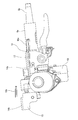
- a housing 10 that houses a reduction gear and the like constituting the electric power steering device is fixed to the front end portion of the steering column 6a. Further, a steering shaft 5a is rotatably supported inside the steering column 6a, and the steering wheel 1 (FIG. 41) is formed at a portion protruding from the rear end opening of the steering column 6a at the rear end portion of the steering shaft 5a. Can be fixed freely.
- the steering column 6a and the housing 10 are supported by a flat plate-like vehicle body side bracket (not shown) fixed to the vehicle body so that the steering column 6a and the housing 10 can be detached forward based on a forward impact load.
- each of the brackets 12 and 13 includes one or two mounting plate portions 14a and 14b, and the mounting plate portions 14a and 14b are respectively formed with notches 15a and 15b that open to the rear edge side. Yes. And the sliding plates 16a and 16b are each assembled
- Each of these sliding plates 16a and 16b is a thin metal plate such as a carbon steel plate or a stainless steel plate, on which a slippery synthetic resin layer such as polyamide resin (nylon) or polytetrafluoroethylene resin (PTFE) is formed. Is formed into a substantially U shape in which the rear end edges of the upper plate portion and the lower plate portion are connected by the connecting plate portion. And the through-hole for inserting a volt
- the column-side bracket 12 and the housing-side bracket 13 are tightened by screwing bolts or studs and nuts inserted through the notches 15a and 15b of the mounting plate portions 14a and 14b and the through holes of the sliding plates 16a and 16b. By this, it is supported by the vehicle body side bracket.
- the bolt or stud comes out of the notches 15a and 15b together with the sliding plates 16a and 16b, and the steering column 6a and the housing 10 move forward along with the column side bracket 12, the housing side bracket 13 and the steering wheel 1. It is allowed to be displaced.
- an energy absorbing member 17 is provided between the bolt or stud and the column side support bracket 12. As the column side bracket 12 is displaced forward, the energy absorbing member 17 is plastically deformed, and the impact energy transmitted from the steering wheel 1 to the column side bracket 12 via the steering shaft 5a and the steering column 6a. To absorb.
- the bolts or studs are pulled out from the notches 15a and 15a, allowing the column side bracket 12 to be displaced forward, and steering.
- the column 6a is displaced forward together with the column side bracket 12.
- the housing side bracket 13 is also allowed to disengage from the vehicle body and the housing side bracket 13 is displaced forward.
- the energy absorbing members 17 are plastically deformed, and the impact transmitted from the driver's body to the column side bracket 12 via the steering shaft 5a and the steering column 6a. Absorb energy and reduce the impact on the driver's body.
- the column side bracket 12 is supported at two positions on the left and right sides with respect to the vehicle body side bracket so that the column side bracket 12 can be detached forward during a secondary collision. Therefore, at the time of a secondary collision, simultaneously disengaging the pair of left and right support portions can stably displace the steering wheel 1 forward without tilting in the state at the moment of occurrence of the secondary collision. It is important for that.
- tuning for simultaneously disengaging the pair of left and right support portions is performed by resistance such as frictional resistance and shear resistance against disengagement of these support portions, and inertia of a portion displaced forward together with the steering column 6a. Since there is an influence such as left and right imbalance regarding the mass, it is a troublesome work.
- FIG. 45 to 47 show the conventional structure described in Patent Document 1.
- FIG. 1 a locking notch 18 that is supported and fixed on the vehicle body side and that is not displaced forward in the case of a secondary collision is opened at the front edge side at the center in the width direction of the vehicle body side bracket 11. 11 is formed with the front edge side open.
- the column side bracket 12a is supported and fixed on the steering column 6b side, and the column side bracket 12a can be displaced forward together with the steering column 6b at the time of a secondary collision.
- the left and right ends of the locking capsule 19 fixed to the column side bracket 12a are locked to the locking notch 18. That is, the locking grooves 20 formed on the left and right side surfaces of the locking capsule 19 are engaged with the left and right side edges of the locking notch 18, respectively. Therefore, the portions present on the upper side of the locking groove 20 at the left and right end portions of the locking capsule 19 are positioned on the upper side of the vehicle body side bracket 11 at both side portions of the locking notch 18.
- the vehicle body side bracket 11 and the locking capsule 19 are formed in portions where these members 11 and 19 are aligned with each other in a state where the locking groove 20 and the left and right side edges of the locking notch 18 are engaged.
- Coupling is performed by press-fitting the locking pin 22 into the small locking holes 21a and 21b.
- These locking pins 22 are formed of a relatively soft material such as an aluminum alloy or a synthetic resin that is torn by an impact load applied during a secondary collision.
- the engaging portion between the locking capsule 19 fixed to the column side support bracket 12a and the vehicle body side fixing bracket 11 is only one portion in the center portion in the width direction. For this reason, it is easy to perform tuning for releasing the engagement of the engaging portion at the time of the secondary collision and stably displacing the steering wheel 1 forward.
- this structure it is effective from the surface that allows the steering column 6b to be released in a stable posture forward at the time of a secondary collision, but the load (detachment load) required for this separation is low and stable. There is room for improvement in terms of further enhancing the protection of the elderly.
- this separation load is suppressed so that the steering column 6b starts to be smoothly displaced forward at the moment when the secondary collision occurs. It is preferable to do. In this way, at the moment of the occurrence of the secondary collision, the forward displacement of the steering column 6b is smoothly performed so that the impact applied to the driver's body colliding with the steering wheel 1 is minimized and the displacement is started.
- the energy absorbing member 17 attached to the steering column 6b is plastically deformed to absorb the impact energy transmitted to the steering wheel 1, thereby further enhancing the protection of the driver. Become.
- the present invention is easy to tune for stably displacing the steering wheel forward at the time of a secondary collision, and can lower and stabilize the detachment load.
- An object of the present invention is to realize a structure of a support device for a steering column that can prevent the steering wheel from being lowered excessively after a secondary collision, if necessary.
- the steering column support device comprises: A vehicle body side bracket that is made of a metal plate and is fixed to the vehicle body at at least two positions on both sides in the width direction and does not displace forward at the time of a secondary collision, and is located between the two positions on both sides in the width direction.
- a vehicle body side bracket provided with a locking thinning portion extending in the front-rear direction;
- a column side bracket that is made of a metal plate and is disposed below the vehicle body side bracket and supports the steering column, and has an upper plate portion that has a width dimension larger than the width dimension of the locking thinning portion at the upper end portion.
- Each of the sliding plate portions includes a pair of upper and lower sliding plate portions each having a width dimension larger than the width dimension of the locking thinning portion, and both end portions in the width direction of the sliding plate portions are part of the vehicle body side bracket.
- a slide member arranged so as to sandwich both side portions of the meat removal portion from both upper and lower sides;
- a connecting member that includes a restraining portion on the upper end side, and that passes through the slide member in a vertical direction;
- the slide member and the coupling member are installed at a rear end portion of the locking and thinning portion, and a part of the vehicle body side bracket is between the pair of slips between the holding portion and the upper plate portion.
- the pair of sliding plate portions may be provided independently of each other, or may be an integrated structure connected by a connecting portion having a width dimension smaller than the width dimension of the locking meat removal portion.
- the slide member is connected to the pair of sliding plate portions by a connecting portion having a width dimension smaller than the width dimension of the locking thinning portion, and the connecting member is connected to a central portion of each sliding plate portion.
- the pair of sliding plate portions are connected by a connecting portion having a width dimension smaller than the width dimension of the locking thinning portion, and the respective sliding plate portions It can also be constituted by an outer slide member having an opening at the center in the width direction of the front end edge and provided with a notch through which the connecting member is inserted.
- the locking and removing portion is formed as two through holes or notches that extend in the front-rear direction and are parallel to each other.
- the slide member and the coupling member are installed in each of the rear end portions of these through holes or notches.
- the locking thinning portion has a front half portion that is a wide portion, and a rear half portion that further extends rearward from two positions in the width direction both ends of the rear end edge of the wide portion, Let it be a through-hole that is two parallel cut-out extensions. And the said slide member and the said connection member are installed in each of the rear-end part of these extension parts.
- the slide members installed on these can be connected to each other in the width direction by the connecting portion to form an integrated structure.
- a reinforcing plate spanned between the slide members is provided on the upper side of the slide member installed on these, and the restraint is performed. Depending on the portion, the upper surface of the reinforcing plate can be pressed downward toward the vehicle body side bracket.
- the above-mentioned locking and removing portion can be constituted by a single through hole or notch extending in the front-rear direction.
- this through hole or notch is formed in the central portion between the two positions on both sides in the width direction.
- the said slide member and the said connection member are installed in the rear-end part of this through-hole or notch.
- the locking thinning portion is opened at the front end edge of the vehicle body side bracket and extends in the front-rear direction or two locking notches that are parallel to each other, or the front half is a wide portion.
- the second half portion further extends backward from the two positions in the width direction both ends of the rear end edge of the wide portion, and each of the two rear portions extends in the front-rear direction and is parallel to each other.
- a lower folded portion formed by folding a part of the vehicle body side bracket facing the rear end edge of the upper plate portion of the column side bracket into a U-shaped cross section toward the front lower side, Holding the rear edge of the upper plate, and A base portion that extends forward from the front edge of the upper plate portion and has a width dimension that is smaller than the width dimension of the notch, and is provided at the distal end of the base, and is wider than the width dimension of the notch.
- An upper folded portion formed by folding an extended plate portion having a holding plate portion having a large width dimension in a U-shaped cross section toward the rear upper side, and a part of the bracket notch on the vehicle body side bracket. It can also be configured to hold down both sides.
- a spacer having a thickness dimension equal to or greater than the thickness dimension of the metal plate constituting the vehicle body side bracket is disposed in the locking thinning portion, and the spacer is disposed between the pair of upper and lower sliding plate portions. It can also be pinched.
- the steering column support device comprises: A vehicle body side bracket that is made of a metal plate and is fixed to the vehicle body at at least two positions on both sides in the width direction and does not displace forward at the time of a secondary collision, and is located between the two positions on both sides in the width direction.
- a vehicle body side bracket provided with a locking thinning portion extending in the front-rear direction;
- a column side bracket that is made of a metal plate and is disposed below the vehicle body side bracket and supports the steering column, and has an upper plate portion that has a width dimension larger than the width dimension of the locking thinning portion at the upper end portion.
- a lower pressing plate portion formed by bending downward with the front end edge facing forward is provided at least in the central portion in the width direction of the rear end edge of the locking thinning portion of the vehicle body side bracket.
- the lower pressing plate portion presses the lower surface of the central portion in the width direction of the upper plate portion of the column side bracket upward, and presses the upper surface of the upper plate portion against the lower surface of the vehicle body side bracket, and / or
- An upper pressing plate portion formed by bending upward in a state where the front edge is directed rearward is provided at a central portion in the width direction of a portion other than the front portion of the upper plate portion, and the vehicle body is provided with the upper pressing plate portion.
- a sliding layer made of a low friction material is interposed between the upper and lower surfaces of the vehicle body side bracket and the surfaces of the members abutted against the upper and lower surfaces before the occurrence of the secondary collision.
- the sliding member is obtained by bending a thin metal plate coated with a coating layer made of a low friction material on one side, and at least the upper surface of the upper sliding plate portion and the lower surface of the lower sliding plate portion.
- This coating layer exists in a portion of the lower sliding plate portion that is located above the lower pressing plate portion, with the surface not coated with the coating layer facing inward, 180 degrees densely.
- a sliding plate provided with a folded back portion is used.
- the coating layer on the upper surface of the upper sliding plate portion is brought into contact with the lower surfaces of the left and right ends of the holding plate and the lower surface of the upper pressing plate portion, and the coating layer on the lower surface of the lower sliding plate portion is While making it contact
- the length in the front-rear direction of the locking thinning portion is greater than the length in the front-rear direction of the upper plate portion of the column side bracket, Even with the steering column and the column side bracket, even when the holding plate is fully displaced forward, at least a part of the holding plate is located above the front end portion of the vehicle body side bracket, and the holding plate falls off. It should be long enough to prevent this.
- an energy absorbing member that absorbs an impact load by plastic deformation is provided between the steering column or a portion that is displaced forward together with the steering column and a portion that is supported on the vehicle body side bracket or the vehicle body or the vehicle body side. It is preferable.
- the steering column support device of the present invention it is easy to tune to stably displace the steering wheel forward at the time of a secondary collision, and the separation load can be reduced and stabilized. Accordingly, a structure capable of preventing the steering wheel from being lowered excessively after the secondary collision is realized.
- the vehicle body side bracket and the column side bracket are positioned at two locations on both sides in the width direction that fix the vehicle body side bracket to the vehicle body side. This is achieved by engaging at a portion between the two. When engaged at a portion between the two positions in the width direction (intermediate portion in the width direction), the impact energy applied to the column side bracket due to the secondary collision is engaged between the vehicle body side bracket and the column side bracket. Since the moment in the bending direction is hardly applied to the column side bracket at the time of the secondary collision, tuning can be facilitated.
- the vehicle body side bracket and the column side bracket are partly connected to a pair of upper and lower parts constituting the slide member. It is intended by sandwiching it with a part of the sliding plate part. Due to the presence of these sliding plate portions, the frictional force acting between the upper and lower surfaces of the vehicle body side bracket and the lower surface of the restraining portion and the upper surface of the upper plate portion of the column side bracket can be kept small. For this reason, the separation load determined based on the frictional force can be reduced and stabilized.
- the vehicle body side bracket and the column side bracket are provided, a lower pressure plate portion is provided on the vehicle body side bracket, and an upper pressure plate portion is provided on the column side bracket.
- a coupling force (this coupling member) by the coupling member. The force acting in the axial direction) can be easily adjusted. For this reason, it is possible to reduce and stabilize the separation load that is the sum of these frictional forces.
- Preventing the steering wheel from descending excessively after the secondary collision can be achieved by sufficiently increasing the length in the front-rear direction of the locking and removing portion.
- the engagement between the restraining portion of the coupling member or the lower surface of the restraining plate and the upper surface of the front end portion of the vehicle body side bracket is achieved. Is prevented, and the front end edge of the locking thinning portion and the coupling member are prevented from being buffered. For this reason, since the column side bracket is restrained from being displaced downward with respect to the vehicle body side bracket, the steering wheel supported by the column side bracket via the steering column is excessively lowered. Can be prevented.
- the positional relationship between the steering wheel and the driver is properly maintained. For example, depending on the degree of the collision accident, the operability of the steering wheel is ensured and the work of retracting the accident vehicle to the road shoulder is facilitated. It is possible to obtain an effect that can be performed in a short time.
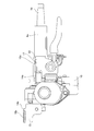
- FIG. 1 is a side view showing a first example of the first embodiment of the present invention.
- FIG. 2 is an enlarged view of the center of FIG.
- FIG. 3 is a plan view of FIG.
- FIG. 4 is an end view seen from the right side of FIG.
- FIG. 5 is a cross-sectional view taken along the line aa in FIG.
- FIG. 6 is a perspective view showing an outer slide base plate (A) and an inner slide base plate (B) that are superimposed to form a slide member.
- FIG. 7 is a view similar to FIG. 3, showing a second example of the first embodiment of the present invention.
- FIG. 8 is a cross-sectional view taken along line bb of FIG. 7, showing a part omitted or seen through.
- FIG. 9 is a partial cross-sectional view showing the third example of the first embodiment of the present invention, viewed from the same direction as FIG.
- FIG. 10 is a schematic perspective view of a slide member showing a fourth example of the first embodiment of the present invention.
- 11 is a schematic cross-sectional view of the slide member of FIG.
- FIG. 12 is a view similar to FIG. 3, showing a fifth example of the first embodiment of the present invention.
- FIG. 13 is a diagram similar to FIG. 4 for the fifth example.
- 14 is a cross-sectional view taken along the line cc of FIG. 12, with a part omitted or seen through.
- FIG. 15 is a view similar to FIG. 3, showing a sixth example of the first embodiment of the present invention.
- FIG. 16 is a cross-sectional view taken along the line dd in FIG. 15, with a part omitted or seen through.
- FIG. 17 is a view similar to FIG. 3, showing a seventh example of the first embodiment of the present invention.
- 18 is a cross-sectional view taken along the line ee of FIG. 17, with a part omitted or seen through.
- FIG. 19 is a view similar to FIG. 3, showing an eighth example of the first embodiment of the present invention.
- FIG. 20 is a view similar to FIG. 3, showing a ninth example of the first embodiment of the present invention.
- FIG. 21 is a diagram similar to FIG. 4 for the ninth example. 22 is a cross-sectional view taken along the line ff of FIG. 20 with a part omitted or seen through.
- FIG. 23 is a perspective view of the front upper portion of the column side bracket used in the ninth example.
- 24 is a cross-sectional view similar to FIG. 5, showing a tenth example of the first embodiment of the present invention.
- 25 is a cross-sectional view taken along the line gg of FIG. 24, with a part omitted.
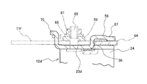
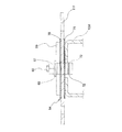
- FIG. 26 is a plan view of relevant parts showing an example of the second embodiment of the present invention.
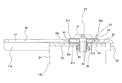
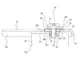
- 27 is a cross-sectional view taken along the line hh of FIG.
- FIG. 28 is a cross-sectional view taken along the line ii of FIG.
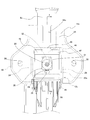
- FIG. 29 is a plan view of a vehicle body side bracket used in the second embodiment.
- 30 is a cross-sectional view taken along the line jj in FIG.
- FIG. 31 is a cross-sectional view taken along the line kk of FIG.
- FIG. 32 is a perspective view showing the vehicle body side bracket used in the second embodiment as seen from the rear lower side.
- FIG. 33 is a plan view of a column side bracket used in the second embodiment.
- 34 is a cross-sectional view taken along line l-l in FIG. 35 is a cross-sectional view taken along the line mm of FIG.
- FIG. 36 is a perspective view showing the upper part of the column side bracket used in the second embodiment as viewed from the rear upper side.
- FIG. 37 is a plan view of a sliding plate used in the second embodiment.
- FIG. 38 is a cross-sectional view taken along line nn of FIG.
- FIG. 39 is a cross-sectional view taken along line oo in FIG.
- FIG. 40 is a perspective view (A) of the sliding plate used in the second embodiment viewed from the front upper side with the lower part omitted, and a perspective view (B) viewed from the front upper side of the upper part omitted.
- FIG. 41 is a partially cut side view showing an example of a conventionally known steering device.
- FIG. 42 is a plan view showing an example of a conventional steering column support device in a normal state.
- 43 is a side view of the apparatus of FIG.
- FIG. 44 is a side view showing a state in which the steering column is displaced forward in the secondary collision in the apparatus of FIG. FIG.
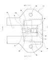
- FIG. 45 is a cross-sectional view relating to a virtual plane existing in a direction orthogonal to the central axis of the steering column, showing an example of a conventional structure.
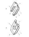
- FIG. 46 is a perspective view showing the structure of FIG. 45 before the vehicle body side bracket and the column side bracket are joined.
- FIG. 47 is a perspective view showing the structure of FIG. 45 in a state where a coupling pin is described instead of omitting the steering column.
- a steering column support device to which the present invention is applied is basically made of a metal plate, is fixed to the vehicle body side at least at two positions on both sides in the width direction, and does not displace forward in a secondary collision.
- the vehicle body side bracket 11a is provided with a locking thinning portion extending in the front-rear direction at a portion between the two positions on both sides in the width direction, and is made of a metal plate and is below the vehicle body side bracket 11a.
- the column side bracket 12b is disposed on the side and supports the steering column, and includes a column side bracket 12b provided with an upper plate portion 23 having a width dimension larger than the width dimension of the locking thinning portion at the upper end.
- a feature of the present invention is a structure for supporting the column side bracket 12b that supports the steering column 6c with respect to the vehicle body side bracket 11a that is supported by the vehicle body so that the column side bracket 11b can be detached forward by an impact caused by a secondary collision. It is in. Therefore, the structure and operation of other parts of the steering column support device, including the structure for supporting the steering column 6c on the column side bracket 12b, is substantially the same as the known steering column support device. The description is omitted only by illustration, and the following description will focus on the structure for supporting the column side bracket 12b with respect to the vehicle body side bracket 11a.
- the column side bracket 12b is made of a metal plate such as a carbon steel plate that has sufficient strength and rigidity and can be plastically deformed. By bending such a metal plate, a substantially U-shape is opened at the bottom. Is formed. More specifically, the column-side bracket 12b has a pair of left and right supports extending upward and downward from the left and right side edges of the upper plate 23 and the upper plate 23 provided at the upper end. A plate portion 24 is provided.
- the steering column 6c is supported between the support plate portions 24 on both sides by a well-known structure so that the vertical position and the front / rear position can be adjusted while the steering shaft 5b is rotatably supported on the inner side of the steering column 6c.
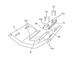
- the vehicle body side bracket 11a is also made of a metal plate such as a carbon steel plate having sufficient strength and rigidity, and the material made of the metal plate is subjected to a punching process using a press or a cutting process using a laser cutter or the like. Is formed into a predetermined shape. In the example shown in the drawing, a portion excluding the front end edge (both side edge portion and rear end edge portion) of the peripheral edge portion of the flat plate-like substrate portion 25 is bent downward to form a bent edge portion 50 to reduce the weight. And ensuring rigidity.
- the width dimension of the body side bracket 11a is narrow in the front half and wide in the rear half. And in this latter half part, the through-hole 26 is each formed in two right-and-left positions of the part near a width direction both ends.
- the vehicle body side bracket 11a is fixed to the vehicle body by bolts or studs inserted through the through holes 26. In this state, the vehicle body side bracket 11a is not displaced forward even during a secondary collision.
- two portions that are long in the front-rear direction and are parallel to each other are provided in portions between the through holes 26 on both sides.
- a through hole 27 is formed.
- the planar shape of the rear end portions of these through holes 27 is inclined in a direction in which the width dimension decreases toward the rear, and is substantially V-shaped.
- the rear end edge of the rear end portion is a coupling member. It is formed in an arc shape that follows the outer peripheral surface of the bolt 29.
- the column side bracket 12b is supported with respect to the vehicle body side bracket 11a so that it can be separated forward (displaced forward from the normal state) by an impact load applied during a secondary collision. For this reason, in the case of the steering column support device of the present example, the upper plate portion 23 of the column side bracket 12b is placed on the rear end portion side of the through hole 27 of the vehicle body side bracket 11a. And a bolt 29 and a nut 30 which are connecting members.
- Each of these slide members 28 is made of a thin metal plate such as a carbon steel plate or a stainless steel plate, and each slide member 28 has a width larger than the width dimension of the through hole 27 that is the locking and removing portion of the vehicle body side bracket 11a.
- a pair of upper and lower sliding plate portions 31a and 31b having dimensions are provided.
- such a slide member 28 is formed by superposing the outer slide base plate 51 shown in FIG. 6A and the inner slide base plate 52 shown in FIG. 6B.
- Each of the slide base plates 51 and 52 has a pair of upper and lower sliding plate portions 31a and 31b provided in parallel with each other.
- the width dimension W of these sliding board parts 31a and 31b is sufficiently larger than the width dimension w of the through-hole 27 (W> w).
- a pair of sliding plate portions 31a constituting the outer slide base plate 51 is formed with through holes 53 at portions of the respective substantially central portions that are engaged with each other. . Further, the front end edges of the upper and lower sliding plates 31a are connected to each other by a connecting portion 33a to integrally form the outer slide base plate 51.
- each of the pair of sliding plates 31b constituting the inner slide base plate 52 is formed in a bifurcated shape by providing a notch portion 32 opened at the front end edge of the central portion in the width direction.
- the front edges of the upper and lower sliding plate portions 31b are connected to each other by a pair of left and right connecting portions 33b provided with the front end opening portions of the upper and lower cutout portions 32 sandwiched from both sides.
- the width dimension of the connecting portions 33a and 33b (a distance D between the outer edges located on the opposite sides) provided for each of the outer and inner slide base plates 51 and 52 constituting the slide member 28 is as follows.
- the through hole 27 has a width dimension w or less (D ⁇ w). In addition, if it is below the width dimension of the through-hole 27, the magnitude relationship between the width dimension of the connection part 33a and the width dimension of the connection parts 33b and 33b will not be questioned.
- the slide member 28 of the present example includes a pair of upper and lower pairs constituting the inner slide base plate 52 between a pair of upper and lower slide plate portions 31 a constituting the outer slide base plate 51. It is configured by sandwiching the sliding plate portion 31b. In this state, the lower surface of the upper sliding plate portion 31a and the upper surface of the sliding plate portion 31b are in contact with the upper surface of the lower sliding plate portion 31a and the lower surface of the sliding plate portion 31b, respectively. Further, the through hole 53 is located at the rear end of the notch 32.
- the surfaces of the outer slide base plate 51 and the inner slide base plate 52 that are in contact with each other are made of polytetrafluoroethylene resin, polyamide resin, molybdenum disulfide, or the like.
- a coating layer of low friction material is provided. In a state in which the slide member 28 is configured by combining the slide base plates 51 and 52, a coating layer exists between the surfaces of the slide base plates 51 and 52 that come into contact with each other. Therefore, the load required for the inner slide base plate 52 to come out of the outer slide base plate 51 can be kept low.
- a locking portion 34 that is bent at a right angle downward is formed at the center of the rear end edge of the upper sliding plate portion 31b in a part of the inner slide base plate 52.
- a locking hole 35 for locking the locking portion 34 is formed in a part of the vehicle body side bracket 11 a that is slightly rearward of the rear end portion of the through hole 27.
- grounding elastic pieces 54 for holding electricity are provided at both ends in the width direction of the rear end edge of the upper sliding plate 31a as part of the outer slide base plate 51. The tip edges of these elastic pieces 54 are not covered with the coating layer, and the metal is exposed.
- both the slide members 28 are assembled to the rear end portions of the respective through holes 27.
- the slide member 28 is attached to the vehicle body side bracket at the front half or the middle portion of the through hole 27 so that the slide plates 31a and 31b of the slide base plates 51 and 52 are positioned above and below the vehicle body side bracket 11a.
- the respective orientations are aligned with the front-rear direction of the through-hole 27, and the connecting members 33a and 33b are located in the through-hole 27.
- both end portions in the width direction of the sliding plate portions 31a and 31b are part of the vehicle body side bracket 11a so as to sandwich both side portions of the through hole 27 which is the locking and removing portion from both the upper and lower sides.
- the sliding member 28 is locked to the locking hole 35 while elastically deforming the upper sliding plate portions 31a and 31b upward, so that the slide member 28 is fixed to the rear end portion of each through hole 27. It is assembled in a position so that it does not fall out accidentally.
- the front end edge of the elastic piece 54 is elastically brought into contact with the upper surface of the vehicle body side bracket 11a, and the vehicle body side bracket 11a and the outer slide base plate 51 are electrically connected.
- the upper surface of the upper plate portion 23 formed on the upper end portion of the column side bracket 12b is arranged on the lower surface of the substrate portion 25 of the vehicle body side bracket 11a, and the lower side of the slide base plates 51 and 52 constituting the slide member 28 is provided. It abuts through the sliding plate portions 31a and 31b. Further, a pair of left and right mounting holes 36 formed in the upper plate portion 23, a through hole 53 of each outer slide base plate 51 constituting the slide member 28, and a notch portion of each inner slide base plate 52. 32 is aligned with the rear end. In this state, the flange portion of the bolt 29 as a coupling member is inserted from above into the through hole 53, the rear end portion of the notch portion 32, and the attachment hole 36.
- a nut 30 is screwed into a lower end portion of the bolt 29 inserted through the slide member 28 and protrudes from the lower surface of the upper plate portion 23, and further tightened with a predetermined torque. Since these nuts 30 are previously fitted and supported in the mounting holes 36, the nuts 30 and the bolts 29 can be easily screwed together and tightened.
- a part of the base plate portion 25 of the vehicle body side bracket 11a is a holding portion provided at the upper end portion of the coupling member. Between the lower surface and the upper surface of the upper plate portion 23 of the column side bracket 12b, the state is sandwiched via the sliding plate portions 31a and 31b.
- the upper plate portion 23 of the column side bracket 12b is connected to the vehicle body side bracket 11a so as to be able to drop forward based on the impact energy applied during the secondary collision.
- the outer slide member 51 slides forward with respect to the inner slide base plate 52 of the slide member 28. That is, since the inner slide base plate 52 does not have a coating layer made of a low friction material between the vehicle body side bracket 11a and the engaging portion 34 and the engaging hole 35 are engaged with each other. The resistance against the forward displacement is relatively large.
- the outer slide base plate 51 has a low resistance to being displaced forward by the coating layer existing between the inner slide base plate 52 and the outer slide base plate 52.
- the outer slide base plate 51 slides forward together with the bolts 29 with respect to the inner slide base plate 52, and these bolts 29 and the column side bracket 12 b are displaced forward together with the outer slide base plate 51.
- the separation load which is a load required to displace forward
- the separation load can be small due to the presence of the coating layer.
- the lower surface of the head portion 37 of the bolt 29 and the column side bracket 12b sandwiching the board portion 25 of the vehicle body side bracket 11a.
- the sliding plate portion 31 b of the inner slide base plate 52 does not exist between the upper surface of the upper plate portion 23. For this reason, as far as the engaging portion between the column side bracket 12b and the vehicle body side bracket 11a is concerned, there is almost no resistance to the bolt 29 and the column side bracket 12b being displaced forward.
- the tuning for stably displacing the steering wheel forward in the case of a secondary collision can be facilitated, but also the separation load can be reduced and stabilized.
- the presence of these sliding plates 31a and 31b is determined.
- the frictional force acting between the upper and lower surfaces of the vehicle body side bracket 11a and the lower surface of the head 37 that is the restraining portion of the bolt 29 that is the coupling member and the upper surface of the upper plate portion 23 of the column side bracket 12b is suppressed to a small level. Can do.
- the value of the detachment load can be arbitrarily adjusted by adjusting the tightening torque between the bolt 29 and the nut 30. Even if this tightening torque is increased to some extent due to the presence of the coating layer, the separation load can be kept low, so that the support strength of the column side bracket 12b with respect to the vehicle body side bracket 11a can be sufficiently secured. In addition, the support rigidity of the steering wheel 1 supported by the column side bracket 12b via the steering column 6c or the like can be sufficiently secured.
- a loosening prevention treatment such as crushing the tip of the male screw portion is performed.
- each through hole 27 in the front-rear direction is set to the state in which the secondary collision has progressed, that is, the impact applied to the steering wheel from the driver's body accompanying the secondary collision.
- the bolt 29 is sufficiently secured so that it does not hit the front edge of the through hole 27.
- a part that is displaced forward together with the steering column 6c such as the steering column 6c or the column side bracket 12b, and the vehicle body side bracket 11 or the vehicle body side including the vehicle body are fixed to the secondary collision.
- An energy absorbing member that allows the column side bracket 12b to be displaced forward while being plastically deformed is provided between a portion that does not displace forward even sometimes.
- the bolt 29 and the upper plate portion 23 of the column side bracket 12b start to be displaced forward with respect to the vehicle body side bracket 11a along with the separation load.
- the energy absorbing member is plastically deformed to absorb the impact energy transmitted from the driver's body to the column side bracket 12b. Since energy absorbing members having various structures have been known, the illustration and detailed description of the energy absorbing member are omitted in the description of this example.
- FIG. 7 to 8 show a second example of the first embodiment of the present invention.
- a rectangular reinforcing plate 38 that is long in the left-right width direction is provided on the upper side of the pair of slide members 28 so as to span between the slide members 28.
- the upper surface of the reinforcing plate 38 is pressed downward toward the board portion 25 of the vehicle body side bracket 11 by the heads 37 of the pair of left and right bolts 29.
- the upper surface of the slide member 28 can be stably suppressed, and the coupling force between the vehicle body side bracket 11a and the column side bracket 12b can be further stabilized.
- the clamping force between the bolt 29 and the nut 30 can be stabilized even if an individual washer is sandwiched between the lower surface of the head portion 37 of the bolt 29 and the upper surface of the slide member 28 as an alternative or in addition. It is possible to stabilize the separation load. Since the configuration and operation of the other parts are the same as those in the first example, the illustration and description regarding the equivalent parts are omitted.
- FIG. 9 shows a third example of the first embodiment of the present invention.
- the slide member 28 is configured between the lower surface of the reinforcing plate 38 and the upper surface of the upper sliding plate portion 31a constituting the slide member 28 and the upper surface of the upper plate portion 23 of the column side bracket 12b.
- the auxiliary sliding plate 39 is sandwiched between the lower sliding plate portion 31b and the lower surface of the sliding plate portion 31b.
- a coating layer made of a low friction material such as polytetrafluoroethylene resin, polyamide resin, or molybdenum disulfide is provided on the surface of the auxiliary sliding plate 39 facing the upper surface or the lower surface of the slide member 28.
- FIG. 10 to 11 show another example of the slide member as a fourth example of the embodiment of the present invention.
- the slide member 28a is obtained by bending a single metal plate such as a carbon steel plate or a stainless steel plate. Although this slide member 28a is configured as a single unit, the shape of the slide member 28a is not limited to the rear end edge of the inner slide base plate 52 shown in FIG. An elastic piece 54 is formed. This slide member 28a is used in place of the slide member 28 in the first to third examples of the first embodiment.
- the column side bracket 12b slides with respect to the slide member 28a together with the bolt 29 (see FIGS. 1 to 5) and moves forward during a secondary collision. Displace. Therefore, a coating layer made of a low friction material is provided on at least the upper surface of the upper sliding plate portion 31e and the lower surface of the lower sliding plate portion 31e among the pair of upper and lower sliding plate portions 31e constituting the slide member 28a.
- a coating layer made of a low friction material is provided on at least the upper surface of the upper sliding plate portion 31e and the lower surface of the lower sliding plate portion 31e among the pair of upper and lower sliding plate portions 31e constituting the slide member 28a.
- a coating layer made of a low friction material is formed at least on the lower surface of the upper sliding plate portion 31e and the upper surface of the lower sliding plate portion 31e.
- FIG. 12 to 14 show a fifth example of the first embodiment of the present invention.
- a substantially U-shaped through-hole 40 is formed as a locking thinning portion of the substrate portion 25 of the vehicle body side bracket 11b.
- the through-hole 40 is a wide portion 41 at the front half and two extension portions 42 each having a notch shape. These extended portions 42 further extend rearward from the positions of the two end portions in the width direction of the rear end edge of the wide portion 41, and are each long in the front-rear direction and parallel to each other.
- the planar shape of the rear end portion of these extension portions 42 is also substantially V-shaped as in the first example.
- bolt 29 and the nut 30 which are coupling members are installed in each of the rear-end part of these extension parts 42.
- the configuration of the slide member 28b is basically the same as the slide member 28 of the first to third examples or the slide member 28a of the fourth example.
- the pair of slide members 28b are formed by a single metal plate in accordance with the through hole 40 as described above, or a pair of slide members 28b.
- Each of the outer and inner slide base plates constituting the slide member 28b is formed of a single metal plate.
- the slide members 28b are connected to each other in the width direction by a connecting portion to form an integrated structure.
- the upper sliding plate portions 31c and 31d constituting the slide member 28b are connected to each other by the connecting portions 43a and 43b, and the lower sliding plate portions 31c and 31d are connected to each other by the connecting portions 43c and 43d. They are connected to each other in the width direction to form an integral structure.
- FIG. 15 to 16 show a sixth example of the first embodiment of the present invention.
- a rectangular reinforcing plate 38 that is long in the left-right width direction is hung between the left and right slide members 28a on the upper side of the pair of left and right slide members 28b and the connecting portion 43a, which are integrally structured. It is provided in a handed state.
- the function of the reinforcing plate 38 is the same as that of the second example, and the structure and operation of the other parts are the same as those of the first example.
- substrate part 25 of the vehicle body side bracket 11c is the one through-hole 27a long in the front-back direction.
- the through-holes 27a are formed in the central portion of the portion between the pair of through-holes 26 formed at two positions on both sides of the substrate portion 25 in the width direction.
- a slide member 28 and bolts 29 and nuts 30 as connecting members are installed at the rear end of the through hole 27a.
- the support rigidity of the column side bracket 12b with respect to the vehicle body side bracket 11c is improved by sandwiching a washer between the head 37 of the bolt 29 and the upper surface of the slide member 28. Can be achieved. Further, by holding an auxiliary sliding plate between the head 37 and the upper surface of the slide member 28, the separation load can be made lower and more stable.
- FIG. 19 shows an eighth example of the first embodiment of the present invention.
- a pair of locking and thinning portions formed on the substrate portion 25 of the vehicle body side bracket 11d are opened to portions that are closer to both sides from the central portion with respect to the width direction of the front edge of the substrate portion 25.
- the locking notch 44a is made by making the locking thinning portions into the locking notches 44a each opening at the front end edge of the substrate portion 25, the stroke of the column side bracket 12b relative to the vehicle body side bracket 11d at the time of the secondary collision can be reduced. It is easy to secure.
- a pair of left and right bolts 29 connecting the vehicle body side bracket 11d and the column side bracket 12b are formed at the center of a pair of through holes 26 formed at both left and right ends of the vehicle body side bracket 11d. It is located on a straight line ⁇ connecting the axes.
- the locking thinning portion formed on the board portion 25 of the vehicle body side bracket 11e is a locking notch 44b that opens at the center in the width direction of the front end edge of the board portion 25.
- the planar shape of the rear end portion of the locking notch 44b is substantially V-shaped.
- the board portion 25 of the vehicle body side bracket 11e is formed by an upper folded portion 47 formed by folding an extended plate portion 46 extending forward from the front end edge portion of the upper plate portion 23a toward the rear upper side in a U-shaped cross section.
- the both sides of the locking notch 44b are held down at the middle part in the front-rear direction.
- the extension plate portion 46 is provided at the base 48 having a width dimension smaller than the width dimension of the locking notch 44b and the tip of the base 48, and the width dimension is a width dimension of the locking notch 44b.
- a larger holding plate portion 49 is provided. Then, the upper surface of the substrate portion 25 is held down by both end portions in the width direction of the holding plate portion 49 with the base portion 48 being inserted into the locking notch 44b.
- the rear end edge portion of the upper plate portion 23a is held by the lower folded portion 45 and the upper surface of the substrate portion 25 is suppressed by the upper folded portion 47, so that the vehicle body side bracket
- the support rigidity of the column side bracket 12c with respect to 11e can be improved.
- the lower folded portion 45 also has an effect of increasing the force for suppressing the column side bracket 12c from being displaced rearward at the time of the primary collision.
- a structure in which a sliding plate provided with a coating layer made of a low friction material on one side or both sides, or a film made of a low friction material can be adopted in the intermediate portion. Since the structure and operation of the other parts are the same as in the seventh example, a duplicate description is omitted.
- [Tenth example of the first embodiment] 24 to 25 show a tenth example of the first embodiment of the present invention.
- a spacer 55 is arranged at the rear end portion in the through hole 27 which is a locking and thinning portion.
- the spacer 55 has a substantially rectangular shape made of a slippery material such as a copper-based alloy, a high-functional resin, or an oil-containing metal, or a substantially V-shaped rear end portion that follows the planar shape of the rear end portion of the through hole 27. It has a thickness dimension equal to or less than the thickness dimension of the substrate portion 25 of the vehicle body side bracket 11a.
- the spacer 55 is formed by forming partial arc-shaped convex portions on both side edges, or rounding the front end corners to a quarter arc shape, etc., during the forward displacement due to a secondary collision. It is preferable not to be caught on the left and right inner edges of the hole 27.
- the maximum width W 55 of the spacer 55 is set to be equal to or smaller than the inner dimension W 27 of the through hole 27 (W 55 ⁇ W 27 ).
- Such a spacer 55 is sandwiched between the upper and lower sliding plate portions 31 b of the inner slide base plate 52 constituting the slide member 28 in a state of being arranged at the rear end portion of the through hole 27.
- the spacer 55 is displaced forward along the through hole 27 so that the column side bracket 12b is smoothly displaced forward. Since the structure and operation of other parts are the same as in the first example, overlapping illustrations and descriptions are omitted.
- the vehicle body side bracket 11f is formed in a flat plate shape by subjecting a material made of a metal plate such as a carbon steel plate having sufficient strength and rigidity to punching with a press or cutting with a laser cutter. ing.
- a material made of a metal plate such as a carbon steel plate having sufficient strength and rigidity to punching with a press or cutting with a laser cutter.
- the width dimension of the vehicle body side bracket 11f incorporated in this example is narrow in the front half and wide in the rear half.
- a locking notch 56 which is a locking thinning portion, is formed at the central portion in the width direction of the vehicle body side bracket 11f so as to open only at the central portion of the front end edge of the vehicle body side bracket 11f.
- the length of the locking notch 56 in the front-rear direction is sufficiently long so that the secondary collision has progressed, that is, the steering wheel is not displaced further forward by the impact energy at the time of the secondary collision. However, the support force of the column side bracket 12d by the vehicle body side bracket 11f is not lost.
- the locking thinning portion it is possible to replace the locking notch 56 with a through hole in which the front end edge of the base plate portion of the vehicle body side bracket does not open.
- the column side bracket 12d employs the following structure as a structure for supporting the vehicle body side bracket 11f so that it can be detached forward by an impact load applied during a secondary collision. is doing. That is, among the following configurations (1) to (3), at least one of the configurations (1) and (2) is combined with the configuration (3), or (1) to (3 ) Is a combination of all the configurations. In this example, a structure in which all the configurations (1) to (3) are combined is adopted.
- a lower side formed by bending downward at a central portion at least in the width direction among the rear end edges of the locking notches 56 which are locking thinning portions of the vehicle body side bracket 11f with the front end edge facing forward.
- the lower surface of the central portion in the width direction of the upper plate portion 23b of the column side bracket 12d is pressed upward by the pressing plate portion 57, and the upper surface of the upper plate portion 23b is pressed against the lower surface of the vehicle body side bracket 11f.
- the vehicle body side bracket 11f is mounted on the vehicle body side bracket 11f by an upper pressing plate portion 58 formed by bending upward in a state where the front end edge is directed rearward at the center portion in the width direction of the portion (second half portion) other than the front portion of the upper plate portion 23b.
- the upper surface of the central portion in the width direction is pressed downward, and the lower surface of the vehicle body side bracket 11f is pressed against the upper surface of the upper plate portion 23b.
- This configuration (1) is such that the base end edge of the lower pressing plate portion 57 is continuous with the center portion in the width direction of the rear end edge of the locking notch 56 at the center portion in the width direction of the rear portion of the vehicle body side bracket 11f. Yes.
- the lower pressing plate portion 57 is a part of the metal plate constituting the vehicle body side bracket 11f, and the front end edge provided by leaving the portion located at the rear end portion of the locking notch 56 is different from the other portion. It can be obtained by bending a protruding plate portion that is a free end that is not connected.
- the base end portion (rear end portion) of the protruding plate portion is bent at a right angle downward with respect to the main body portion of the vehicle body side bracket 11 f to form the lower connecting plate portion 62. Further, the portion near the proximal end of the intermediate portion of the protruding plate portion is directed forward and bent at a right angle with respect to the lower connecting plate portion 62, and the intermediate portion or the distal end portion of the protruding plate portion is the main body portion of the vehicle body side bracket 11f.
- the lower elastic pressing plate portion 63 is substantially parallel to the lower side.
- the upper surface of the tip end portion of the lower elastic pressing plate portion 63 is connected to the lower surface of the central portion in the width direction of the upper plate portion 23b constituting the column side bracket 12d via a part of the sliding plate 64 which is a sliding member. It is pressed elastically. Then, both end portions in the width direction of the upper plate portion 23b are elastically pressed toward the lower surfaces of the portions located on the left and right sides of the locking notch 56 in the vehicle body side bracket 11f, and the longitudinal direction of the column side bracket 12d. The intermediate portion is supported to the vehicle body side bracket 11f so as to be able to be detached forward by an impact load applied during a secondary collision.
- an upper pressing plate portion 58 formed by bending upward with the tip edge directed rearward is provided in the rear half of the central portion in the width direction of the upper plate portion 23b constituting the column side bracket 12d. And formed.
- slit-like notches 65 opened at the rear edge of the upper plate portion 23d are parallel to each other at two positions separated in the width direction at the central portion of the upper plate portion 23d. Is formed.
- the base end portion (front end portion) of the rectangular plate portion sandwiched by the notches 65 on both sides in the width direction is bent at a right angle upward with respect to the main body portion of the upper plate portion 23d, and the upper connecting plate portion 66.
- the portion near the proximal end of the intermediate portion of the rectangular plate portion is directed rearward and bent at a right angle with respect to the upper connecting plate portion 66, and the intermediate portion or the distal end portion of the rectangular plate portion is the main body of the upper plate portion 23b.
- the upper elastic pressing plate portion 67 is substantially parallel to the portion.
- the lower surface of the front end portion of the upper elastic pressing plate portion 67 is placed on the upper surface of the central portion in the width direction of the rear end portion of the body portion of the vehicle body side bracket 11f via the other portion of the sliding plate 64 which is a sliding member. It is made to contact elastically.
- the front end portion (rear end portion) of the upper elastic pressing plate portion 67 is caulked and deformed slightly downward, and this deformed portion is formed on a partial upper surface of the vehicle body side bracket 11f on the sliding plate 64. Is pressed through.
- the upper elastic pressing plate portion 67 causes the rear end portion of the vehicle body side bracket 11f to have an upper surface at two positions in the width direction existing on both sides of the notch 65 in the upper plate portion 23d constituting the column side bracket 12d.
- the rear end portion of the column side bracket 12d is supported to the vehicle body side bracket 11f so as to be able to be separated forward by an impact load applied during a secondary collision.
- the lower pressing plate portion 57 and the upper pressing plate portion 58 of the configurations (1) and (2) are both installed at the center in the width direction of the vehicle body side bracket 11f and the column side bracket 12d, and the center in the width direction. Are matched with each other.
- a restraining plate 59 is installed on the upper surface of the vehicle body side bracket 11 f so as to be hung over both side portions of the locking notch 56.
- the restraining plate 59 is made of a material that has a spring property and / or does not rust between the sliding plate 64 with which the lower surfaces of both ends abut, such as a stainless spring steel plate, a galvanized steel plate, and a phosphor bronze plate. It is preferable to use it.
- the frictional force prevents the column side bracket 12d from being displaced forward with respect to the vehicle body side bracket 11f during normal operation.
- This column side bracket 12d can be displaced forward against the force.
- this frictional force static frictional force
- reducing the surface pressure of the contact surface existing in the coupling structure obtained by the configurations (1) to (3) is to support the column side bracket 12d with respect to the vehicle body side bracket 11f.
- a sliding plate 64 which is a sliding member, is interposed in the coupling structure portion obtained by the configurations (1) to (3) so as to keep this frictional force low.
- the sliding plate 64 which is a sliding member is obtained by bending a thin metal plate such as a stainless steel plate. One surface of the metal thin plate is coated with a coating layer of a low friction material such as polytetrafluoroethylene resin, polyamide resin, molybdenum disulfide.
- the shape of the sliding plate 64 will be described with reference to FIGS.
- the sliding plate 64 includes a connecting plate portion 69 provided at a rear end portion, and an upper plate portion 70 that is bent at a right angle toward the front from the upper and lower end edges of the connecting plate portion 69 and extends. And a lower plate portion 71.
- the coating layer is present on the rear surface of the connecting plate portion 69, the upper surface of the upper plate portion 70, and the lower surface of the lower plate portion 71.
- a portion of the upper plate portion 70 that is aligned with the locking notch 56 of the vehicle body side bracket 11f in the assembled state to the steering column support device is provided with a notch that opens forward. Therefore, the upper plate portion 70 has a bifurcated shape except for the rear end portion.
- the lower plate portion 71 is also provided with a notch opened forward at a portion aligned with the locking notch 56, and the portion excluding the rear end portion has a bifurcated shape.
- the lower plate portion 71 protrudes forward at the center portion in the width direction of the rear end portion of the notch, at the portion located above the lower pressing plate portion 57 in the assembled state to the steering column support device.
- a protruding plate portion 72 is formed.
- a folded portion that is folded back 180 degrees densely with the front end portion (front end portion) of the protruding plate portion 72 facing inward with the surface not coated with the coating layer facing upward. 73 is provided. Therefore, the coating layer is present not only on the lower surface but also on the upper surface of the tip portion of the protruding plate portion 72.
- the front end portion of the upper plate portion 70 is connected to the upper surface of the vehicle body side bracket 11f and both end portions of the holding plate 59. It is sandwiched between the lower surface. In this state, the coating layer contacts the lower surfaces of both end portions of the holding plate 59.
- the portion other than the protruding plate portion 72 is sandwiched between the lower surface of the vehicle body side bracket 11f and the upper surface of the upper plate portion 23b constituting the column side bracket 12d. In this state, the coating layer contacts the upper surface of the upper plate portion 23b.
- the folded-back portion 73 provided at the distal end portion of the protruding plate portion 72 is sandwiched between the lower surface of the upper plate portion 23b and the upper surface of the lower pressing plate portion 57 provided in the vehicle body side bracket 11f.
- the coating layer contacts not only the upper surface of the lower pressing plate portion 57 but also the lower surface of the upper plate portion 23b.
- the lower pressing plate portion 57 is set to be equal to or larger than the width W of the base portion of the lower connecting plate portion 62 of the lower pressing plate portion 57. It is made to approach to the back part of the notch formed in 71.
- FIG. As shown in FIGS. 26 to 28, when the sliding plate 64 is assembled to the steering column support device, the sliding plate 64 is engaged with the rear end edge of the vehicle body side bracket 11f and the connecting plate portion 69. Displacement forward is prevented.
- the sliding plate 64 remains in the same position even during a secondary collision.
- a coating layer is present in all of the contact portions between the column side bracket 12d and the holding plate 59 and the sliding plate 64 that are displaced forward during a secondary collision. Therefore, the separation load required for the column side bracket 12d to move forward at the time of the secondary collision can be reduced and stabilized.
- a member 74 is provided.
- the latching structure of the energy absorption member 74 in vehicle body side, such as the vehicle body side bracket 11f, is well-known, the description is abbreviate
- the structure of the energy absorbing member is not limited to that shown in the figure, and may be provided between the steering column or a portion displaced forward together with the steering column, and the vehicle body side bracket or the vehicle body or the portion fixed to the vehicle body side. It is possible to employ any energy absorbing member having a structure capable of absorbing an impact load by plastic deformation.
- the lower pressing plate portion 57 presses the lower surface of the central portion in the width direction of the upper plate portion 23b of the column side bracket 12d upward, and / or Then, the upper surface of the central portion in the width direction of the vehicle body side bracket 11f is pressed downward by the upper pressing plate portion 58. As a result, the vehicle body side bracket 11f and the column side bracket 12d are pressed against each other in the vertical direction, and the upper plate portion 23b of the column side bracket 12d is coupled and supported to the vehicle body side bracket 11f. In this state, the holding plate 29 is not yet assembled.
- an intermediate separation load which is a load at which the column side bracket 12d starts to be displaced in the front-rear direction with respect to the vehicle body side bracket 11f.
- the separation load is measured by pushing or pulling the column side bracket 12d forward while the vehicle body side bracket 11f is supported so as not to move, and measuring the load at the moment when the column side bracket 12d is slightly displaced. Do. At the moment when the column bracket 12d is slightly displaced, the force applied to the column side bracket 12d is released so that the column side bracket 12d is not displaced further forward. If necessary, the displacement may be restored.
- the detachment load based on the configurations (1) and (2) is measured.
- the detachment load in this state is an appropriate detachment load required for the steering column support device after the assembly is completed.
- the pressing force of the lower pressing plate portion 57 and the upper pressing plate portion 58 is adjusted so as to be smaller than a certain appropriate separation load.
- the holding plate 59 is made of an elastic metal plate, even if the value of the tightening torque by the coupling member slightly deviates from the target value, the increase in the separation load does not vary greatly. Therefore, if the bolt 60 and the nut 61 are tightened with a predetermined torque, the separation load can be appropriately increased and the proper separation load can be obtained with high accuracy.
- the bolt 60 is disposed so as to be inserted in the vertical direction through the sliding plate 64 that is a sliding member from the upper plate portion 23b side of the column side bracket 12d. Then, the nut 61 is screwed into the upper end portion of the bolt 60 inserted through the sliding plate 64 and protruding from the upper surface of the holding plate 59.
- the nut 61 corresponds to a holding portion provided on the upper end side, and a part of the vehicle body side bracket 1f is provided between the lower surface of the nut 61 and the upper surface of the upper plate portion 23b of the column side bracket 12d.
- a part of the vehicle body side bracket 1f is provided between the lower surface of the nut 61 and the upper surface of the upper plate portion 23b of the column side bracket 12d.
- the upper plate portion 23b and the holding plate 59 of the column side bracket 12d are moved forward against the appropriate separation load with respect to the vehicle body side bracket 11f at the time of a secondary collision. Start to displace. And with this displacement, the energy absorbing member 74 is plastically deformed to absorb the impact energy transmitted from the driver's body to the column side bracket 12d.
- the length of the locking notch 56 in the front-rear direction depends on the state in which the secondary collision has progressed, that is, depending on the impact energy applied to the steering wheel from the driver's body due to the secondary collision. Even in a state where 6 is no longer displaced forward, the length enough to prevent the holding plate 59 from slipping forward from the locking notch 56 is secured. That is, at the time of the secondary collision, even when the holding plate 59 is displaced forward together with the steering column 6 and the column side bracket 12d, at least the rear end portion of the both ends in the width direction of the holding plate 59 is the front end portion of the vehicle body side bracket 11f. The front-rear direction dimension of the vehicle body side bracket 11f is secured so that the holding plate 59 can be prevented from falling off.
- the coupling member In any embodiment of the present invention, a bolt and a nut are appropriate as the coupling member because the tightening torque can be easily adjusted by the coupling member.
- other coupling members including rivets can be used as long as the tightening torque can be adjusted.
- the connecting structure of the vehicle body side bracket and the column side bracket is 1 at the center of the portion between the pair of through holes 26 formed at two positions on both sides in the width direction of the vehicle body side bracket. Although only a portion is provided, it can be provided at a plurality of locations as long as it is a portion between the pair of left and right through holes 26 that is a coupling and fixing portion between the vehicle body side bracket and the vehicle body.
- the present invention is not limited to a steering column support device having both a tilt mechanism for adjusting the vertical position of the steering wheel and a telescopic mechanism for adjusting the front-rear position, but only the tilt mechanism or the telescopic mechanism.
- the present invention can be widely applied to a steering column support device provided only with a steering column, and further to a steering column support device with a fixed position of the steering wheel that does not include any of these mechanisms.
Landscapes
- Engineering & Computer Science (AREA)
- Chemical & Material Sciences (AREA)
- Combustion & Propulsion (AREA)
- Transportation (AREA)
- Mechanical Engineering (AREA)
- Steering Controls (AREA)
Abstract
Priority Applications (3)
| Application Number | Priority Date | Filing Date | Title |
|---|---|---|---|
| CN201180002481.4A CN102656078B (zh) | 2010-12-21 | 2011-11-09 | 转向柱用支承装置 |
| US13/386,658 US8534705B2 (en) | 2010-12-21 | 2011-11-09 | Steering column support apparatus |
| EP11811304.2A EP2657104B1 (fr) | 2010-12-21 | 2011-11-09 | Dispositif de support pour colonne de direction |
Applications Claiming Priority (6)
| Application Number | Priority Date | Filing Date | Title |
|---|---|---|---|
| JP2010-283971 | 2010-12-21 | ||
| JP2010283971A JP5360045B2 (ja) | 2010-12-21 | 2010-12-21 | ステアリングコラム用支持装置及びその組立方法 |
| JP2010293157 | 2010-12-28 | ||
| JP2010-293157 | 2010-12-28 | ||
| JP2011-204214 | 2011-09-20 | ||
| JP2011204214A JP5464189B2 (ja) | 2010-12-28 | 2011-09-20 | ステアリングコラム用支持装置 |
Publications (1)
| Publication Number | Publication Date |
|---|---|
| WO2012086331A1 true WO2012086331A1 (fr) | 2012-06-28 |
Family
ID=47020698
Family Applications (1)
| Application Number | Title | Priority Date | Filing Date |
|---|---|---|---|
| PCT/JP2011/075847 WO2012086331A1 (fr) | 2010-12-21 | 2011-11-09 | Dispositif de support pour colonne de direction |
Country Status (4)
| Country | Link |
|---|---|
| US (1) | US8534705B2 (fr) |
| EP (1) | EP2657104B1 (fr) |
| CN (1) | CN102656078B (fr) |
| WO (1) | WO2012086331A1 (fr) |
Cited By (2)
| Publication number | Priority date | Publication date | Assignee | Title |
|---|---|---|---|---|
| JP2012131444A (ja) * | 2010-12-24 | 2012-07-12 | Toyota Motor Corp | ステアリングコラムの車体への組み付け方法、及び、ステアリングコラムの離脱機構 |
| CN104487315A (zh) * | 2012-07-23 | 2015-04-01 | 丰田自动车株式会社 | 转向管柱装置 |
Families Citing this family (20)
| Publication number | Priority date | Publication date | Assignee | Title |
|---|---|---|---|---|
| CN102438878B (zh) * | 2010-08-06 | 2015-02-25 | 日本精工株式会社 | 冲击吸收式转向装置 |
| JP5429109B2 (ja) * | 2010-08-20 | 2014-02-26 | 日本精工株式会社 | ステアリング装置 |
| EP2664517B1 (fr) * | 2010-10-22 | 2017-11-22 | NSK Ltd. | Dispositif de support de colonne de direction et procédé d'assemblage de celui-ci |
| US8955883B2 (en) * | 2011-11-07 | 2015-02-17 | Nsk Ltd. | Steering apparatus |
| US8991865B2 (en) * | 2012-09-27 | 2015-03-31 | Mclaren Automotive Limited | Collapsible steering column |
| JP5971725B2 (ja) | 2013-01-30 | 2016-08-17 | 株式会社ジェイテクト | ステアリングコラム装置 |
| JP6150333B2 (ja) * | 2013-01-30 | 2017-06-21 | 株式会社ジェイテクト | ステアリング装置 |
| JP6021107B2 (ja) | 2013-01-30 | 2016-11-02 | 株式会社ジェイテクト | ステアリングコラム装置 |
| JP2014189154A (ja) * | 2013-03-27 | 2014-10-06 | Showa Corp | ステアリング装置 |
| JP6115769B2 (ja) * | 2013-05-24 | 2017-04-19 | 株式会社ジェイテクト | ステアリング装置 |
| JP6239875B2 (ja) | 2013-06-28 | 2017-11-29 | 株式会社ジェイテクト | ステアリング装置 |
| JP6108347B2 (ja) | 2013-07-17 | 2017-04-05 | 株式会社ジェイテクト | ステアリング装置 |
| JP6103536B2 (ja) * | 2013-07-18 | 2017-03-29 | 株式会社ジェイテクト | ステアリング装置 |
| JP6241652B2 (ja) * | 2013-08-21 | 2017-12-06 | 株式会社ジェイテクト | ステアリング装置 |
| EP2998194B1 (fr) * | 2013-10-30 | 2017-12-06 | NSK Ltd. | Dispositif de direction |
| CN107148379B (zh) * | 2014-11-04 | 2018-12-11 | 日本精工株式会社 | 转向柱装置 |
| CN105109544A (zh) * | 2015-08-19 | 2015-12-02 | 安徽江淮汽车股份有限公司 | 一种汽车转向管柱总成及其溃缩吸能装置 |
| US10035479B2 (en) * | 2016-03-15 | 2018-07-31 | Nsk Ltd. | Steering apparatus |
| DE102016220533A1 (de) * | 2016-10-19 | 2018-04-19 | Thyssenkrupp Ag | Lenksäule mit Energieabsorptionsvorrichtung für ein Kraftfahrzeug |
| JP6831982B1 (ja) * | 2020-07-31 | 2021-02-24 | 株式会社協和エクシオ | パラペット吊り下げ式アンテナ架台 |
Citations (8)
| Publication number | Priority date | Publication date | Assignee | Title |
|---|---|---|---|---|
| JPS51119231U (fr) * | 1975-03-24 | 1976-09-28 | ||
| JPS51121929U (fr) | 1975-03-28 | 1976-10-02 | ||
| JPS5625981U (fr) | 1979-08-03 | 1981-03-10 | ||
| JPS5625981Y2 (fr) * | 1976-04-23 | 1981-06-19 | ||
| JPH0746595Y2 (ja) * | 1989-09-06 | 1995-10-25 | 本田技研工業株式会社 | ステアリングコラム支持構造 |
| JP2000006821A (ja) | 1998-06-19 | 2000-01-11 | Nippon Seiko Kk | 衝撃吸収式ステアリングコラム装置 |
| JP2005096731A (ja) * | 2003-09-02 | 2005-04-14 | Toyota Motor Corp | 衝撃吸収式ステアリングコラム装置 |
| JP2005219641A (ja) | 2004-02-05 | 2005-08-18 | Nsk Ltd | ステアリングコラム装置 |
Family Cites Families (25)
| Publication number | Priority date | Publication date | Assignee | Title |
|---|---|---|---|---|
| JPS60169365A (ja) | 1984-02-14 | 1985-09-02 | Nissan Motor Co Ltd | ステアリング装置 |
| EP0295378B1 (fr) * | 1987-06-19 | 1992-07-22 | Dr.Ing.h.c. F. Porsche Aktiengesellschaft | Fixation comportant un élément déformable pour colonne de direction de véhicule à moteur |
| JPH0322968U (fr) * | 1989-07-13 | 1991-03-11 | ||
| JP2829199B2 (ja) * | 1992-08-07 | 1998-11-25 | 株式会社山田製作所 | ステアリングコラムの衝撃吸収装置 |
| US5356179A (en) * | 1993-09-13 | 1994-10-18 | Chrysler Corporation | Energy absorbing device for a steering column |
| US5390955A (en) * | 1993-12-23 | 1995-02-21 | Chrysler Corporation | Steering column release capsules |
| FR2714649B1 (fr) * | 1994-01-06 | 1996-03-15 | Nacam | Organe d'absorption d'énergie notamment pour colonne de direction de véhicule automobile. |
| FR2737175B1 (fr) * | 1995-07-26 | 1997-10-10 | Nacam | Dispositif d'absorption d'energie et de guidage pour colonne de direction de vehicule automobile |
| US6062100A (en) * | 1998-12-17 | 2000-05-16 | General Motors Corporation | Connection for energy absorbing steering column |
| JP3468711B2 (ja) * | 1999-02-18 | 2003-11-17 | 株式会社山田製作所 | ステアリングコラムの衝撃吸収装置 |
| JP2004338509A (ja) * | 2003-05-14 | 2004-12-02 | Toyota Motor Corp | 衝撃吸収式ステアリングコラム装置 |
| GB0403613D0 (en) * | 2004-02-18 | 2004-03-24 | Nsk Steering Sys Europ Ltd | Steering apparatus |
| KR100599481B1 (ko) * | 2004-09-06 | 2006-07-12 | 현대모비스 주식회사 | 조향컬럼의 충격흡수장치 |
| US7472924B2 (en) * | 2005-03-28 | 2009-01-06 | Fuji Kiko Co., Ltd. | Steering column device for vehicle |
| JP5528868B2 (ja) * | 2010-03-19 | 2014-06-25 | 株式会社ジェイテクト | ステアリング装置 |
| WO2011158787A1 (fr) * | 2010-06-16 | 2011-12-22 | 日本精工株式会社 | Support de colonne de direction |
| JP5327164B2 (ja) * | 2010-08-24 | 2013-10-30 | 日本精工株式会社 | 電動式パワーステアリング装置を備えた衝撃吸収式ステアリング装置 |
| JP5327165B2 (ja) * | 2010-08-26 | 2013-10-30 | 日本精工株式会社 | 電動式パワーステアリング装置を備えた衝撃吸収式ステアリング装置 |
| JP5499995B2 (ja) * | 2010-08-26 | 2014-05-21 | 日本精工株式会社 | 電動式パワーステアリング装置を備えた衝撃吸収式ステアリング装置 |
| WO2012049920A1 (fr) * | 2010-10-15 | 2012-04-19 | 日本精工株式会社 | Dispositif de direction d'automobile |
| EP2628656B1 (fr) * | 2010-10-15 | 2018-02-21 | NSK Ltd. | Dispositif de support pour colonne de direction |
| EP2636573B1 (fr) * | 2010-11-02 | 2018-01-03 | NSK Ltd. | Dispositif d'assistance de colonne de direction |
| US8622427B2 (en) * | 2010-11-12 | 2014-01-07 | Nsk Ltd. | Steering column support apparatus |
| WO2012066900A1 (fr) * | 2010-11-15 | 2012-05-24 | 日本精工株式会社 | Dispositif de soutien pour colonne de direction |
| WO2012090616A1 (fr) * | 2010-12-28 | 2012-07-05 | 日本精工株式会社 | Dispositif de support pour colonne de direction et son procédé d'assemblage |
-
2011
- 2011-11-09 EP EP11811304.2A patent/EP2657104B1/fr not_active Not-in-force
- 2011-11-09 CN CN201180002481.4A patent/CN102656078B/zh not_active Expired - Fee Related
- 2011-11-09 US US13/386,658 patent/US8534705B2/en not_active Expired - Fee Related
- 2011-11-09 WO PCT/JP2011/075847 patent/WO2012086331A1/fr active Application Filing
Patent Citations (8)
| Publication number | Priority date | Publication date | Assignee | Title |
|---|---|---|---|---|
| JPS51119231U (fr) * | 1975-03-24 | 1976-09-28 | ||
| JPS51121929U (fr) | 1975-03-28 | 1976-10-02 | ||
| JPS5625981Y2 (fr) * | 1976-04-23 | 1981-06-19 | ||
| JPS5625981U (fr) | 1979-08-03 | 1981-03-10 | ||
| JPH0746595Y2 (ja) * | 1989-09-06 | 1995-10-25 | 本田技研工業株式会社 | ステアリングコラム支持構造 |
| JP2000006821A (ja) | 1998-06-19 | 2000-01-11 | Nippon Seiko Kk | 衝撃吸収式ステアリングコラム装置 |
| JP2005096731A (ja) * | 2003-09-02 | 2005-04-14 | Toyota Motor Corp | 衝撃吸収式ステアリングコラム装置 |
| JP2005219641A (ja) | 2004-02-05 | 2005-08-18 | Nsk Ltd | ステアリングコラム装置 |
Non-Patent Citations (1)
| Title |
|---|
| See also references of EP2657104A4 * |
Cited By (4)
| Publication number | Priority date | Publication date | Assignee | Title |
|---|---|---|---|---|
| JP2012131444A (ja) * | 2010-12-24 | 2012-07-12 | Toyota Motor Corp | ステアリングコラムの車体への組み付け方法、及び、ステアリングコラムの離脱機構 |
| CN104487315A (zh) * | 2012-07-23 | 2015-04-01 | 丰田自动车株式会社 | 转向管柱装置 |
| EP2876022A4 (fr) * | 2012-07-23 | 2015-10-28 | Toyota Motor Co Ltd | Dispositif de colonne de direction |
| CN104487315B (zh) * | 2012-07-23 | 2016-08-17 | 丰田自动车株式会社 | 转向管柱装置 |
Also Published As
| Publication number | Publication date |
|---|---|
| CN102656078B (zh) | 2014-10-29 |
| US20120267884A1 (en) | 2012-10-25 |
| EP2657104A1 (fr) | 2013-10-30 |
| EP2657104B1 (fr) | 2017-04-26 |
| EP2657104A4 (fr) | 2016-04-06 |
| CN102656078A (zh) | 2012-09-05 |
| US8534705B2 (en) | 2013-09-17 |
Similar Documents
| Publication | Publication Date | Title |
|---|---|---|
| WO2012086331A1 (fr) | Dispositif de support pour colonne de direction | |
| WO2012090616A1 (fr) | Dispositif de support pour colonne de direction et son procédé d'assemblage | |
| JP4897541B2 (ja) | 衝撃吸収式操舵装置 | |
| JP5626164B2 (ja) | ステアリングコラム用支持装置 | |
| JP5327164B2 (ja) | 電動式パワーステアリング装置を備えた衝撃吸収式ステアリング装置 | |
| JP5293825B2 (ja) | 衝撃吸収式ステアリング装置 | |
| WO2012026258A1 (fr) | Dispositif de direction à absorption d'énergie | |
| WO2016186147A1 (fr) | Dispositif de direction | |
| WO2012060193A1 (fr) | Dispositif d'assistance de colonne de direction | |
| WO2012063609A1 (fr) | Dispositif de support pour colonne de direction | |
| US9238476B2 (en) | Tilt steering apparatus | |
| JP6142970B2 (ja) | ステアリング装置 | |
| US9096260B1 (en) | Impact absorbing steering apparatus | |
| JP5267528B2 (ja) | 衝撃吸収式ステアリング装置 | |
| JP2002362341A (ja) | 自動車用ペダル支持構造 | |
| JP5464189B2 (ja) | ステアリングコラム用支持装置 | |
| JP5360045B2 (ja) | ステアリングコラム用支持装置及びその組立方法 | |
| US10086865B2 (en) | Steering device | |
| JP3409513B2 (ja) | 衝撃吸収式ステアリング装置 | |
| JP5360047B2 (ja) | ステアリングコラム用支持装置 | |
| JP5327189B2 (ja) | ステアリングコラム用支持装置及びその組立方法 | |
| WO2012026259A1 (fr) | Dispositif de direction absorbant les chocs | |
| JP5708839B2 (ja) | ステアリングコラム用支持装置 | |
| JP2005132288A (ja) | 車両用ステアリングコラム装置、及び車両用車体艤装品 | |
| JP2012140066A (ja) | ステアリングコラム用支持装置及びその組立方法 |
Legal Events
| Date | Code | Title | Description |
|---|---|---|---|
| WWE | Wipo information: entry into national phase |
Ref document number: 201180002481.4 Country of ref document: CN |
|
| REEP | Request for entry into the european phase |
Ref document number: 2011811304 Country of ref document: EP |
|
| WWE | Wipo information: entry into national phase |
Ref document number: 2011811304 Country of ref document: EP |
|
| WWE | Wipo information: entry into national phase |
Ref document number: 13386658 Country of ref document: US |
|
| 121 | Ep: the epo has been informed by wipo that ep was designated in this application |
Ref document number: 11811304 Country of ref document: EP Kind code of ref document: A1 |
|
| NENP | Non-entry into the national phase |
Ref country code: DE |