自動車用ステアリング装置は、図41に示すように、ステアリングホイール1の回転をステアリングギアユニット2の入力軸3に伝達し、この入力軸3の回転に伴って左右1対のタイロッド4を押し引きして、操舵輪である前輪に舵角を付与するように構成されている。ステアリングホイール1は、ステアリングシャフト5の後端部に支持固定されており、このステアリングシャフト5は、円筒状のステアリングコラム6を軸方向に挿通した状態で、このステアリングコラム6に回転自在に支持されている。また、ステアリングシャフト5の前端部は、自在継手7を介して中間シャフト8の後端部に接続し、この中間シャフト8の前端部は、別の自在継手9を介して、入力軸3に接続されている。なお、中間シャフト8は、トルクを伝達可能に、かつ、衝撃荷重により全長を収縮可能に構成されており、衝突事故における自動車が他の自動車などに衝突する一次衝突の際に、ステアリングギアユニット2の後方への変位に拘らず、ステアリングシャフト5を介してステアリングホイール1が後方に向けて変位して、運転者の身体を突き上げてしまうことが防止されている。
As shown in FIG. 41, the steering apparatus for an automobile transmits the rotation of the steering wheel 1 to the input shaft 3 of the steering gear unit 2, and pushes and pulls the pair of left and right tie rods 4 as the input shaft 3 rotates. Thus, the steering angle is given to the front wheels which are the steered wheels. The steering wheel 1 is supported and fixed at the rear end portion of the steering shaft 5. The steering shaft 5 is rotatably supported by the steering column 6 with the cylindrical steering column 6 inserted in the axial direction. ing. The front end portion of the steering shaft 5 is connected to the rear end portion of the intermediate shaft 8 via a universal joint 7, and the front end portion of the intermediate shaft 8 is connected to the input shaft 3 via another universal joint 9. Has been. The intermediate shaft 8 is configured to be able to transmit torque and to be shrunk in its entire length by an impact load, and the steering gear unit 2 in a primary collision in which a vehicle collides with another vehicle or the like in a collision accident. Regardless of the rearward displacement, the steering wheel 1 is prevented from being displaced rearward via the steering shaft 5 and pushing up the driver's body.
このような自動車用ステアリング装置において、運転者のさらなる保護のため、衝突事故の際に、衝撃エネルギを吸収しつつ、ステアリングホイールを前方に変位させる構造とすることが必要とされる。すなわち、衝突事故の際には、一次衝突に続いて、運転者の身体がステアリングホイール1に衝突する二次衝突が発生する。この二次衝突の際に、運転者の身体に加わる衝撃を緩和して、運転者の保護を図るために、ステアリングホイール1を支持したステアリングコラム6を車体に対し、二次衝突に伴う前方への衝撃荷重により前方に離脱可能に支持するとともに、このステアリングコラム6とともに前方に変位する部分と車体との間に、塑性変形することで衝撃荷重を吸収するエネルギ吸収部材を設けたステアリングコラム用支持装置の構造は知られており(特許文献1~3参照)、すでに広く実施されている。
In such an automobile steering device, for further protection of the driver, it is necessary to have a structure that displaces the steering wheel forward while absorbing impact energy in the event of a collision. That is, in the case of a collision accident, a secondary collision in which the driver's body collides with the steering wheel 1 occurs following the primary collision. In order to reduce the impact applied to the driver's body during the secondary collision and to protect the driver, the steering column 6 supporting the steering wheel 1 is moved forward with respect to the vehicle body due to the secondary collision. Steering column support provided with an energy absorbing member that absorbs the impact load by plastic deformation between the vehicle body and the portion displaced forward together with the steering column 6. The structure of the apparatus is known (see Patent Documents 1 to 3) and has already been widely implemented.
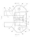
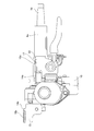
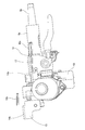
図42~図44は、このようなステアリング装置の1例を示している。ステアリングコラム6aの前端部に、電動式パワーステアリング装置を構成する減速機などを収納するハウジング10を固定している。また、ステアリングコラム6aの内側にステアリングシャフト5aを、回転のみ自在に支持しており、このステアリングシャフト5aの後端部でステアリングコラム6aの後端開口から突出した部分に、ステアリングホイール1(図41参照)を固定自在としている。そして、ステアリングコラム6aおよびハウジング10を、車体に固定された平板状の車体側ブラケット(図示せず)に対し、前方に向いた衝撃荷重に基づいて前方への離脱を可能に支持している。
42 to 44 show an example of such a steering apparatus. A housing 10 that houses a reduction gear and the like constituting the electric power steering device is fixed to the front end portion of the steering column 6a. Further, a steering shaft 5a is rotatably supported inside the steering column 6a, and the steering wheel 1 (FIG. 41) is formed at a portion protruding from the rear end opening of the steering column 6a at the rear end portion of the steering shaft 5a. Can be fixed freely. The steering column 6a and the housing 10 are supported by a flat plate-like vehicle body side bracket (not shown) fixed to the vehicle body so that the steering column 6a and the housing 10 can be detached forward based on a forward impact load.
このため、ステアリングコラム6aの中間部に支持したコラム側ブラケット12と、ハウジング10に支持したハウジング側ブラケット13とを、いずれも前方に向いた衝撃荷重により前方に離脱するように、車体に対し支持している。これらのブラケット12、13はいずれも、1~2箇所の取付板部14a、14bを備え、これらの取付板部14a、14bに、それぞれ後端縁側に開口する切り欠き15a、15bを形成している。そして、これらの切り欠き15a、15bを覆う状態で、これらのブラケット12、13の左右両端寄り部分に、それぞれ滑り板16a、16bを組み付けている。
For this reason, the column side bracket 12 supported on the intermediate portion of the steering column 6a and the housing side bracket 13 supported on the housing 10 are both supported with respect to the vehicle body so as to be separated forward by an impact load directed forward. is doing. Each of the brackets 12 and 13 includes one or two mounting plate portions 14a and 14b, and the mounting plate portions 14a and 14b are respectively formed with notches 15a and 15b that open to the rear edge side. Yes. And the sliding plates 16a and 16b are each assembled | attached to the part near these both ends of these brackets 12 and 13 in the state which covers these notches 15a and 15b.
これらの滑り板16a、16bはそれぞれ、表面に、ポリアミド樹脂(ナイロン)、ポリ四フッ化エチレン樹脂(PTFE)などの滑りやすい合成樹脂製の層を形成した、炭素鋼板、ステンレス鋼板などの金属薄板を曲げ成形することにより、上板部と下板部の後端縁同士を連結板部により連結した、略U字形としている。そして、それぞれの上板部と下板部の互いに整合する部分に、ボルトもしくはスタッドを挿通するための通孔を形成している。これらの滑り板16a、16bを、それぞれの取付板部14a、14bに装着した状態で、これらの通孔は、これらの取付板部14a、14bに形成した、切り欠き15a、15bに整合する。
Each of these sliding plates 16a and 16b is a thin metal plate such as a carbon steel plate or a stainless steel plate, on which a slippery synthetic resin layer such as polyamide resin (nylon) or polytetrafluoroethylene resin (PTFE) is formed. Is formed into a substantially U shape in which the rear end edges of the upper plate portion and the lower plate portion are connected by the connecting plate portion. And the through-hole for inserting a volt | bolt or a stud is formed in the part which mutually aligns each upper board part and lower board part. With these sliding plates 16a and 16b attached to the respective mounting plate portions 14a and 14b, these through holes are aligned with the notches 15a and 15b formed in these mounting plate portions 14a and 14b.
コラム側ブラケット12およびハウジング側ブラケット13は、取付板部14a、14bの切り欠き15a、15bおよび滑り板16a、16bの通孔を挿通した、ボルトもしくはスタッドとナットとを螺合し、さらに締め付けることにより、車体側ブラケットに支持される。二次衝突時に、ボルトもしくはスタッドが滑り板16a、16bとともに、切り欠き15a、15bから抜け出して、ステアリングコラム6aおよびハウジング10が、コラム側ブラケット12、ハウジング側ブラケット13、およびステアリングホイール1とともに、前方に変位することが許容される。
The column-side bracket 12 and the housing-side bracket 13 are tightened by screwing bolts or studs and nuts inserted through the notches 15a and 15b of the mounting plate portions 14a and 14b and the through holes of the sliding plates 16a and 16b. By this, it is supported by the vehicle body side bracket. At the time of the secondary collision, the bolt or stud comes out of the notches 15a and 15b together with the sliding plates 16a and 16b, and the steering column 6a and the housing 10 move forward along with the column side bracket 12, the housing side bracket 13 and the steering wheel 1. It is allowed to be displaced.
また、図示の例では、ボルトもしくはスタッドと、コラム側支持ブラケット12との間に、エネルギ吸収部材17を設けている。そして、このコラム側ブラケット12が前方に変位するのに伴って、エネルギ吸収部材17を塑性変形させ、ステアリングホイール1から、ステアリングシャフト5aおよびステアリングコラム6aを介してコラム側ブラケット12に伝わった衝撃エネルギを吸収するようにしている。
In the illustrated example, an energy absorbing member 17 is provided between the bolt or stud and the column side support bracket 12. As the column side bracket 12 is displaced forward, the energy absorbing member 17 is plastically deformed, and the impact energy transmitted from the steering wheel 1 to the column side bracket 12 via the steering shaft 5a and the steering column 6a. To absorb.
二次衝突時には、図43に示す通常の状態から、図44に示すように、ボルトもしくはスタッドが、切り欠き15a、15aから抜け出して、コラム側ブラケット12が前方に変位することを許容し、ステアリングコラム6aが、このコラム側ブラケット12とともに前方に変位した状態となる。この際、ハウジング側ブラケット13に関しても、車体から離脱し、このハウジング側ブラケット13が前方に変位することが許容される。そして、コラム側ブラケット12の前方への変位に伴って、エネルギ吸収部材17がそれぞれ塑性変形し、運転者の身体から、ステアリングシャフト5aおよびステアリングコラム6aを介して、コラム側ブラケット12に伝わった衝撃エネルギを吸収し、運転者の身体に加わる衝撃を緩和する。
At the time of the secondary collision, from the normal state shown in FIG. 43, as shown in FIG. 44, the bolts or studs are pulled out from the notches 15a and 15a, allowing the column side bracket 12 to be displaced forward, and steering. The column 6a is displaced forward together with the column side bracket 12. At this time, the housing side bracket 13 is also allowed to disengage from the vehicle body and the housing side bracket 13 is displaced forward. As the column side bracket 12 is displaced forward, the energy absorbing members 17 are plastically deformed, and the impact transmitted from the driver's body to the column side bracket 12 via the steering shaft 5a and the steering column 6a. Absorb energy and reduce the impact on the driver's body.
図42~図44に示した構造では、コラム側ブラケット12を左右両側2箇所位置で車体側ブラケットに対し、二次衝突時に前方への離脱を可能に支持している。したがって、二次衝突時には、左右1対の支持部の係合を同時に外れさせることが、ステアリングホイール1を前方に、二次衝突発生の瞬間の状態のまま傾斜させずに、安定して変位させるためには重要となる。しかしながら、左右1対の支持部の係合を同時に外れさせるためのチューニングは、これらの支持部を外れさせることに対する摩擦抵抗、剪断抵抗などの抵抗や、ステアリングコラム6aとともに前方に変位する部分の慣性質量に関する左右のアンバランスなどの影響があるため、手間の掛かる作業となる。
42 to 44, the column side bracket 12 is supported at two positions on the left and right sides with respect to the vehicle body side bracket so that the column side bracket 12 can be detached forward during a secondary collision. Therefore, at the time of a secondary collision, simultaneously disengaging the pair of left and right support portions can stably displace the steering wheel 1 forward without tilting in the state at the moment of occurrence of the secondary collision. It is important for that. However, tuning for simultaneously disengaging the pair of left and right support portions is performed by resistance such as frictional resistance and shear resistance against disengagement of these support portions, and inertia of a portion displaced forward together with the steering column 6a. Since there is an influence such as left and right imbalance regarding the mass, it is a troublesome work.
二次衝突時にステアリングコラムの前方への離脱を安定させるためには、特許文献1に記載された構造を採用することが効果的である。図45~図47は、特許文献1に記載された従来構造を示している。この構造では、車体側に支持固定されて、二次衝突時にも前方に変位することのない車体側ブラケット11の幅方向中央部に前端縁側が開口した係止切り欠き18を、この車体側ブラケット11の前端縁側が開口する状態で形成している。また、ステアリングコラム6b側にコラム側ブラケット12aを支持固定して、二次衝突時に、このコラム側ブラケット12aを、ステアリングコラム6bとともに前方に変位可能としている。
It is effective to adopt the structure described in Patent Document 1 in order to stabilize the separation of the steering column to the front during a secondary collision. 45 to 47 show the conventional structure described in Patent Document 1. FIG. In this structure, a locking notch 18 that is supported and fixed on the vehicle body side and that is not displaced forward in the case of a secondary collision is opened at the front edge side at the center in the width direction of the vehicle body side bracket 11. 11 is formed with the front edge side open. Further, the column side bracket 12a is supported and fixed on the steering column 6b side, and the column side bracket 12a can be displaced forward together with the steering column 6b at the time of a secondary collision.
さらに、このコラム側ブラケット12aに固定した係止カプセル19の左右端部を、係止切り欠き18に係止している。すなわち、この係止カプセル19の左右側面のそれぞれに形成した係止溝20を、係止切り欠き18の左右側縁部のそれぞれに係合させている。したがって、係止カプセル19の左右端部で係止溝20の上側に存在する部分は、係止切り欠き18の両側部分で、車体側ブラケット11の上側に位置している。車体側ブラケット11と係止カプセル19とは、係止溝20と係止切り欠き18の左右側縁部とを係合させた状態で、これらの部材11、19の互いに整合する部分に形成した小係止孔21a、21bに係止ピン22を圧入することで結合する。これらの係止ピン22は、アルミニウム系合金、合成樹脂などの、二次衝突時に加わる衝撃荷重で裂断する、比較的軟質の材料により形成されている。
Furthermore, the left and right ends of the locking capsule 19 fixed to the column side bracket 12a are locked to the locking notch 18. That is, the locking grooves 20 formed on the left and right side surfaces of the locking capsule 19 are engaged with the left and right side edges of the locking notch 18, respectively. Therefore, the portions present on the upper side of the locking groove 20 at the left and right end portions of the locking capsule 19 are positioned on the upper side of the vehicle body side bracket 11 at both side portions of the locking notch 18. The vehicle body side bracket 11 and the locking capsule 19 are formed in portions where these members 11 and 19 are aligned with each other in a state where the locking groove 20 and the left and right side edges of the locking notch 18 are engaged. Coupling is performed by press-fitting the locking pin 22 into the small locking holes 21a and 21b. These locking pins 22 are formed of a relatively soft material such as an aluminum alloy or a synthetic resin that is torn by an impact load applied during a secondary collision.
二次衝突時に、ステアリングコラム6bからコラム側ブラケット12aを介して、係止カプセル19に、前方に向いた衝撃荷重が加わると、係止ピン22が裂断する。そして、係止カプセル19が係止切り欠き18から前方に抜け出して、ステアリングコラム6b、さらにはステアリングシャフト5を介してこのステアリングコラム6bに支持されたステアリングホイール1の前方への変位が許容される。
During a secondary collision, if an impact load directed forward is applied from the steering column 6b to the locking capsule 19 via the column side bracket 12a, the locking pin 22 is torn. Then, the locking capsule 19 is pulled forward from the locking notch 18, and the steering column 6b and further the steering wheel 1 supported by the steering column 6b via the steering shaft 5 are allowed to be displaced forward. .
図45~図47に示した構造の場合、コラム側支持ブラケット12aに固定した係止カプセル19と車体側固定ブラケット11との係合部が、幅方向中央部の1個所のみである。このため、二次衝突時にこの係合部の係合を解除し、ステアリングホイール1を前方に安定して変位させるためのチューニングが容易になる。ただし、この構造の場合、二次衝突時にステアリングコラム6bを、前方に安定した姿勢で離脱させる面からは有効であるが、この離脱に要する荷重(離脱荷重)を低く、かつ安定させて、運転者の保護をより一層充実させる面からは改良の余地がある。
45 to 47, the engaging portion between the locking capsule 19 fixed to the column side support bracket 12a and the vehicle body side fixing bracket 11 is only one portion in the center portion in the width direction. For this reason, it is easy to perform tuning for releasing the engagement of the engaging portion at the time of the secondary collision and stably displacing the steering wheel 1 forward. However, in this structure, it is effective from the surface that allows the steering column 6b to be released in a stable posture forward at the time of a secondary collision, but the load (detachment load) required for this separation is low and stable. There is room for improvement in terms of further enhancing the protection of the elderly.
すなわち、二次衝突時に運転者の身体に加わる衝撃をより低く抑えるためには、この離脱荷重を低く抑えて、二次衝突発生の瞬間にステアリングコラム6bが前方に、円滑に変位し始めるようにすることが好ましい。このように、二次衝突発生の瞬間に、ステアリングコラム6bの前方への変位開始を円滑に行わせて、ステアリングホイール1に衝突した運転者の身体に加わる衝撃をできるだけ小さく抑えるとともに、変位開始後、二次衝突の進行に伴って、ステアリングコラム6bに付設したエネルギ吸収部材17を塑性変形させ、ステアリングホイール1に伝わった衝撃エネルギを吸収することにより、運転者の保護充実がより図られることとなる。
That is, in order to suppress the impact applied to the driver's body at the time of the secondary collision, this separation load is suppressed so that the steering column 6b starts to be smoothly displaced forward at the moment when the secondary collision occurs. It is preferable to do. In this way, at the moment of the occurrence of the secondary collision, the forward displacement of the steering column 6b is smoothly performed so that the impact applied to the driver's body colliding with the steering wheel 1 is minimized and the displacement is started. As the secondary collision progresses, the energy absorbing member 17 attached to the steering column 6b is plastically deformed to absorb the impact energy transmitted to the steering wheel 1, thereby further enhancing the protection of the driver. Become.
ただし、図45~図47に示した構造の場合、二次衝突発生の瞬間に、ステアリングコラム6bの前方への変位を開始させるためには、複数の係止ピン22を裂断する必要がある。これらの係止ピン22を裂断するためには、ある程度大きな衝撃荷重が必要になり、離脱荷重を低く抑える面からは不利になる。一方、図42~図44に示した構造では、二次衝突時におけるステアリングコラム6aの姿勢を安定させるための手間が面倒であることに加えて、コラム側ブラケット12を車体側に組み付けるためのボルトなどの締め付けトルクが少し変わるだけで、離脱荷重が大きく変動するため、締め付けトルクの管理も面倒になる。このような理由から、これらの従来構造では、二次衝突時にステアリングコラム1を、前方に安定した姿勢で離脱させ、しかも離脱荷重を低く、かつ安定させることが困難となっている。
However, in the case of the structure shown in FIGS. 45 to 47, in order to start the forward displacement of the steering column 6b at the moment of the occurrence of the secondary collision, it is necessary to break the plurality of locking pins 22. . In order to tear off these locking pins 22, a certain large impact load is required, which is disadvantageous from the viewpoint of keeping the separation load low. On the other hand, in the structure shown in FIGS. 42 to 44, in addition to troublesome work for stabilizing the posture of the steering column 6a at the time of the secondary collision, a bolt for assembling the column side bracket 12 to the vehicle body side. Even if the tightening torque changes a little, the separation load varies greatly, which makes it difficult to manage the tightening torque. For these reasons, in these conventional structures, it is difficult to disengage the steering column 1 in a stable posture in the forward collision, and to lower and stabilize the disengagement load.
[第1実施形態の第1例]
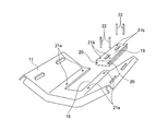
図1~図6は、本発明の第1実施形態の第1例を示している。本発明が適用されるステアリングコラム用支持装置は、基本的に、金属板製で、少なくとも幅方向両側2箇所位置で車体側に固定され、二次衝突時に前方に変位することのない車体側ブラケットであって、前記幅方向両側2箇所位置の間にある部分に、前後方向に伸長する係止除肉部が設けられている車体側ブラケット11aと、金属板製で、車体側ブラケット11aの下側に配置され、ステアリングコラムを支持するコラム側ブラケットであって、前記係止除肉部の幅寸法よりも大きな幅寸法を有する上板部23を上端部に備えるコラム側ブラケット12bを備える。そして、本発明の特徴は、ステアリングコラム6cを支持するコラム側ブラケット12bを、車体に支持した車体側ブラケット11aに対し、二次衝突に伴う衝撃により前方への離脱を可能に支持するための構造にある。よって、コラム側ブラケット12bにステアリングコラム6cを支持するための構造を含む、ステアリングコラム用支持装置のその他の部分の構造およびその作用については、公知のステアリングコラム用支持装置とほぼ同様であるから、図示のみで説明は省略し、以下、コラム側ブラケット12bを車体側ブラケット11aに対して支持するための構造を中心に説明する。
[First Example of First Embodiment]
1 to 6 show a first example of the first embodiment of the present invention. A steering column support device to which the present invention is applied is basically made of a metal plate, is fixed to the vehicle body side at least at two positions on both sides in the width direction, and does not displace forward in a secondary collision. The vehicle body side bracket 11a is provided with a locking thinning portion extending in the front-rear direction at a portion between the two positions on both sides in the width direction, and is made of a metal plate and is below the vehicle body side bracket 11a. The column side bracket 12b is disposed on the side and supports the steering column, and includes a column side bracket 12b provided with an upper plate portion 23 having a width dimension larger than the width dimension of the locking thinning portion at the upper end. A feature of the present invention is a structure for supporting the column side bracket 12b that supports the steering column 6c with respect to the vehicle body side bracket 11a that is supported by the vehicle body so that the column side bracket 11b can be detached forward by an impact caused by a secondary collision. It is in. Therefore, the structure and operation of other parts of the steering column support device, including the structure for supporting the steering column 6c on the column side bracket 12b, is substantially the same as the known steering column support device. The description is omitted only by illustration, and the following description will focus on the structure for supporting the column side bracket 12b with respect to the vehicle body side bracket 11a.
コラム側ブラケット12bは、十分な強度および剛性を有し、かつ塑性変形可能な、炭素鋼板などの金属板製であり、このような金属板を曲げ加工することにより、下方が開口した略U字形に形成されている。より具体的には、コラム側ブラケット12bは、上端部に設けられた上板部23と、この上板部23の左右両側縁からそれぞれ下方に向け直角に折れ曲がって伸長する、左右1対の支持板部24を備える。ステアリングコラム6cは、その内側にステアリングシャフト5bを回転自在に支持した状態で、両側の支持板部24の間に、周知の構造により、上下位置および前後位置の調節を可能に支持される。
The column side bracket 12b is made of a metal plate such as a carbon steel plate that has sufficient strength and rigidity and can be plastically deformed. By bending such a metal plate, a substantially U-shape is opened at the bottom. Is formed. More specifically, the column-side bracket 12b has a pair of left and right supports extending upward and downward from the left and right side edges of the upper plate 23 and the upper plate 23 provided at the upper end. A plate portion 24 is provided. The steering column 6c is supported between the support plate portions 24 on both sides by a well-known structure so that the vertical position and the front / rear position can be adjusted while the steering shaft 5b is rotatably supported on the inner side of the steering column 6c.
一方、車体側ブラケット11aも同様に、十分な強度および剛性を有する、炭素鋼板などの金属板製であり、この金属板製の素材に、プレスによる打ち抜き加工、レーザカッタなどによる切断加工を施すことにより所定形状に形成されている。図示の例では、平板状の基板部25の周縁部のうちで前端縁を除く部分(両側縁部および後端縁部)を下方に曲げ形成して、折り曲げ縁部50を形成し、軽量化と剛性確保との両立を図っている。
On the other hand, the vehicle body side bracket 11a is also made of a metal plate such as a carbon steel plate having sufficient strength and rigidity, and the material made of the metal plate is subjected to a punching process using a press or a cutting process using a laser cutter or the like. Is formed into a predetermined shape. In the example shown in the drawing, a portion excluding the front end edge (both side edge portion and rear end edge portion) of the peripheral edge portion of the flat plate-like substrate portion 25 is bent downward to form a bent edge portion 50 to reduce the weight. And ensuring rigidity.
車体側ブラケット11aの幅寸法は、前半部で狭く、後半部で広くなっている。そして、この後半部のうちで、幅方向両端寄り部分の左右2箇所位置に、それぞれ通孔26を形成している。車体側ブラケット11aは、これらの通孔26を挿通したボルトまたはスタッドにより、車体に対し固定される。この状態で、車体側ブラケット11aは、二次衝突時にも、前方に変位することはない。このような車体側ブラケット11aのうちで、この車体側ブラケット11aの幅方向に関して、両側の通孔26の間にある部分に、係止除肉部として、それぞれが前後方向に長く互いに平行な2本の透孔27を形成している。これらの透孔27の後端部の平面形状は、それぞれ後方に向かうほど幅寸法が小さくなる方向に傾斜し、略V字状となっており、この後端部の後端縁は、結合部材であるボルト29の外周面に倣った円弧状に形成されている。
The width dimension of the body side bracket 11a is narrow in the front half and wide in the rear half. And in this latter half part, the through-hole 26 is each formed in two right-and-left positions of the part near a width direction both ends. The vehicle body side bracket 11a is fixed to the vehicle body by bolts or studs inserted through the through holes 26. In this state, the vehicle body side bracket 11a is not displaced forward even during a secondary collision. Among such vehicle body side brackets 11a, in the width direction of the vehicle body side bracket 11a, two portions that are long in the front-rear direction and are parallel to each other are provided in portions between the through holes 26 on both sides. A through hole 27 is formed. The planar shape of the rear end portions of these through holes 27 is inclined in a direction in which the width dimension decreases toward the rear, and is substantially V-shaped. The rear end edge of the rear end portion is a coupling member. It is formed in an arc shape that follows the outer peripheral surface of the bolt 29.
コラム側ブラケット12bは、車体側ブラケット11aに対して、二次衝突時に加わる衝撃荷重により前方への離脱(通常状態よりも前方への変位)を可能に支持される。このため、本例のステアリングコラム用支持装置の場合には、コラム側ブラケット12bの上板部23を、車体側ブラケット11aの透孔27の後端部側に、それぞれ1対ずつのスライド部材28と、結合部材であるボルト29およびナット30とにより、結合している。これらのスライド部材28はそれぞれ、炭素鋼板、ステンレス鋼板などの金属薄板製であり、それぞれのスライド部材28は、車体側ブラケット11aの係止除肉部である透孔27の幅寸法よりも大きな幅寸法を有する上下1対の滑り板部31a、31bを備える。本例では、このようなスライド部材28を、図6(A)に示した外側スライド素板51と図6(B)に示した内側スライド素板52とを重ね合わせて形成している。これらのスライド素板51、52はそれぞれ、互いに平行に設けられた、上下1対の滑り板部31a、31bを有する。そして、これらの滑り板部31a、31bの幅寸法Wは、透孔27の幅寸法wよりも十分に大きくなっている(W>w)。
The column side bracket 12b is supported with respect to the vehicle body side bracket 11a so that it can be separated forward (displaced forward from the normal state) by an impact load applied during a secondary collision. For this reason, in the case of the steering column support device of the present example, the upper plate portion 23 of the column side bracket 12b is placed on the rear end portion side of the through hole 27 of the vehicle body side bracket 11a. And a bolt 29 and a nut 30 which are connecting members. Each of these slide members 28 is made of a thin metal plate such as a carbon steel plate or a stainless steel plate, and each slide member 28 has a width larger than the width dimension of the through hole 27 that is the locking and removing portion of the vehicle body side bracket 11a. A pair of upper and lower sliding plate portions 31a and 31b having dimensions are provided. In this example, such a slide member 28 is formed by superposing the outer slide base plate 51 shown in FIG. 6A and the inner slide base plate 52 shown in FIG. 6B. Each of the slide base plates 51 and 52 has a pair of upper and lower sliding plate portions 31a and 31b provided in parallel with each other. And the width dimension W of these sliding board parts 31a and 31b is sufficiently larger than the width dimension w of the through-hole 27 (W> w).
これらの滑り板部31a、31bのうち、外側スライド素板51を構成する1対の滑り板部31aには、それぞれのほぼ中央部の互いに係合する部分に、通孔53が形成されている。また、上下の滑り板31aの前端縁同士を、連結部33aにより連結して、外側スライド素板51を一体に形成している。一方、内側スライド素板52を構成する1対の滑り板31bにはそれぞれ、幅方向中央部の前端縁に開口する切り欠き部32を設けることで、二股状に形成されている。そして、上下の滑り板部31bの前端縁同士を、上下の切り欠き部32の前端開口部を両側から挟む状態で設けた左右1対の連結部33bにより連結している。スライド部材28を構成する、外側および内側のスライド素板51、52ごとに1対ずつ設けられた、連結部33a、33bの幅寸法(互いに反対側に位置する外端縁同士の間隔D)は、透孔27の幅寸法w以下(D≦w)となっている。なお、透孔27の幅寸法以下であれば、連結部33aの幅寸法と、連結部33b、33bの幅寸法との大小関係が問われることはない。
Among these sliding plate portions 31a and 31b, a pair of sliding plate portions 31a constituting the outer slide base plate 51 is formed with through holes 53 at portions of the respective substantially central portions that are engaged with each other. . Further, the front end edges of the upper and lower sliding plates 31a are connected to each other by a connecting portion 33a to integrally form the outer slide base plate 51. On the other hand, each of the pair of sliding plates 31b constituting the inner slide base plate 52 is formed in a bifurcated shape by providing a notch portion 32 opened at the front end edge of the central portion in the width direction. The front edges of the upper and lower sliding plate portions 31b are connected to each other by a pair of left and right connecting portions 33b provided with the front end opening portions of the upper and lower cutout portions 32 sandwiched from both sides. The width dimension of the connecting portions 33a and 33b (a distance D between the outer edges located on the opposite sides) provided for each of the outer and inner slide base plates 51 and 52 constituting the slide member 28 is as follows. The through hole 27 has a width dimension w or less (D ≦ w). In addition, if it is below the width dimension of the through-hole 27, the magnitude relationship between the width dimension of the connection part 33a and the width dimension of the connection parts 33b and 33b will not be questioned.
本例のスライド部材28は、図3~図5に示すように、外側スライド素板51を構成する上下1対の滑り板部31aの間に、内側スライド素板52を構成する上下1対の滑り板部31bを挟持することにより、構成される。この状態で、上側の滑り板部31aの下面と滑り板部31bの上面が、下側の滑り板部31aの上面と滑り板部31bの下面とが、それぞれ当接する。また、通孔53が、切り欠き部32の後端部に位置する。本例の場合には、スライド素板51、52の片面で、外側スライド素板51と内側スライド素板52の互いに当接する面に、ポリ四フッ化エチレン樹脂、ポリアミド樹脂、二硫化モリブデンなどの低摩擦材のコーティング層を設けている。これらのスライド素板51、52を組み合わせて、スライド部材28を構成した状態で、これらのスライド素板51、52の互いに当接する面の間には、コーティング層が存在する。したがって、内側スライド素板52が外側スライド素板51から抜け出るために要する荷重を低く抑えることができる。
As shown in FIGS. 3 to 5, the slide member 28 of the present example includes a pair of upper and lower pairs constituting the inner slide base plate 52 between a pair of upper and lower slide plate portions 31 a constituting the outer slide base plate 51. It is configured by sandwiching the sliding plate portion 31b. In this state, the lower surface of the upper sliding plate portion 31a and the upper surface of the sliding plate portion 31b are in contact with the upper surface of the lower sliding plate portion 31a and the lower surface of the sliding plate portion 31b, respectively. Further, the through hole 53 is located at the rear end of the notch 32. In the case of this example, on one side of the slide base plates 51 and 52, the surfaces of the outer slide base plate 51 and the inner slide base plate 52 that are in contact with each other are made of polytetrafluoroethylene resin, polyamide resin, molybdenum disulfide, or the like. A coating layer of low friction material is provided. In a state in which the slide member 28 is configured by combining the slide base plates 51 and 52, a coating layer exists between the surfaces of the slide base plates 51 and 52 that come into contact with each other. Therefore, the load required for the inner slide base plate 52 to come out of the outer slide base plate 51 can be kept low.
また、内側スライド素板52の一部で、上側の滑り板部31bの後端縁中央部に、下方に向け直角に折れ曲がった係止部34が形成されている。一方、車体側ブラケット11aの一部で、透孔27の後端部よりも少し後方に寄った部分に、係止部34を係止するための係止孔35が形成されている。さらに、外側スライド素板51の一部で、上側の滑り板31aの後端縁の幅方向両端部に、通電保持のためのアース用弾性片54が設けられている。これらの弾性片54の先端縁は、コーティング層に覆われずに、金属が露出した状態となっている。
Further, a locking portion 34 that is bent at a right angle downward is formed at the center of the rear end edge of the upper sliding plate portion 31b in a part of the inner slide base plate 52. On the other hand, a locking hole 35 for locking the locking portion 34 is formed in a part of the vehicle body side bracket 11 a that is slightly rearward of the rear end portion of the through hole 27. Furthermore, grounding elastic pieces 54 for holding electricity are provided at both ends in the width direction of the rear end edge of the upper sliding plate 31a as part of the outer slide base plate 51. The tip edges of these elastic pieces 54 are not covered with the coating layer, and the metal is exposed.
コラム側ブラケット12bの上端部に設けた上板部23を車体側ブラケット11aに結合するには、まず、両方のスライド部材28をそれぞれの透孔27の後端部に組み付ける。この組み付け作業は、それぞれのスライド素板51、52の滑り板部31a、31bが車体側ブラケット11aの上下に位置するように、透孔27の前半部ないしは中間部においてスライド部材28を車体側ブラケット11aに嵌め込み、それぞれの向きを透孔27の前後方向に合わせ、連結部33a、33bが透孔27内に位置する状態で、これらのスライド部材28をそれぞれの透孔27内を後端部側に移動させる。このようにして、これらの滑り板部31a、31bの幅方向両端部が、車体側ブラケット11aの一部で、係止除肉部である透孔27の両側部分を上下両側から挟持するように配置する。さらに、上側の滑り板部31a、31bを上方に弾性変形させつつ、係止部34を係止孔35に係止させることで、スライド部材28が、それぞれの透孔27の後端部の所定位置に、不用意に脱落しないように組み付けられる。同時に、弾性片54の先端縁を車体側ブラケット11aの上面に弾性的に当接させて、この車体側ブラケット11aと外側スライド素板51とを、電気的に導通させる。
In order to connect the upper plate portion 23 provided at the upper end portion of the column side bracket 12b to the vehicle body side bracket 11a, first, both the slide members 28 are assembled to the rear end portions of the respective through holes 27. In this assembling operation, the slide member 28 is attached to the vehicle body side bracket at the front half or the middle portion of the through hole 27 so that the slide plates 31a and 31b of the slide base plates 51 and 52 are positioned above and below the vehicle body side bracket 11a. 11a, the respective orientations are aligned with the front-rear direction of the through-hole 27, and the connecting members 33a and 33b are located in the through-hole 27. Move to. In this way, both end portions in the width direction of the sliding plate portions 31a and 31b are part of the vehicle body side bracket 11a so as to sandwich both side portions of the through hole 27 which is the locking and removing portion from both the upper and lower sides. Deploy. Further, the sliding member 28 is locked to the locking hole 35 while elastically deforming the upper sliding plate portions 31a and 31b upward, so that the slide member 28 is fixed to the rear end portion of each through hole 27. It is assembled in a position so that it does not fall out accidentally. At the same time, the front end edge of the elastic piece 54 is elastically brought into contact with the upper surface of the vehicle body side bracket 11a, and the vehicle body side bracket 11a and the outer slide base plate 51 are electrically connected.
次に、コラム側ブラケット12bの上端部に形成した上板部23の上面を、車体側ブラケット11aの基板部25の下面に、スライド部材28を構成するスライド素板51、52の、下側の滑り板部31a、31bを介して突き当てる。また、上板部23に形成した、左右1対の取付孔36と、スライド部材28を構成する、それぞれの外側スライド素板51の通孔53と、それぞれの内側スライド素板52の切り欠き部32の後端部とを整合させる。この状態で、結合部材であるボルト29の杆部を、通孔53と切り欠き部32の後端部と取付孔36とに、上方から挿通する。そして、スライド部材28を挿通したボルト29の下端部であって上板部23の下面から突出した部分に、ナット30を螺合し、さらに、所定のトルクで締め付ける。なお、これらのナット30は、あらかじめ取付孔36に嵌合支持されているので、これらのナット30とボルト29との螺合およびその締め付け作業は、容易に行うことができる。これらのナット30とボルト29とを締め付けた状態で、車体側ブラケット11aの基板部25の一部は、結合部材の上端部に設けられた抑え部分である、これらのボルト29の頭部37の下面と、コラム側ブラケット12bの上板部23の上面との間に、滑り板部31a、31bを介して挟持された状態となる。
Next, the upper surface of the upper plate portion 23 formed on the upper end portion of the column side bracket 12b is arranged on the lower surface of the substrate portion 25 of the vehicle body side bracket 11a, and the lower side of the slide base plates 51 and 52 constituting the slide member 28 is provided. It abuts through the sliding plate portions 31a and 31b. Further, a pair of left and right mounting holes 36 formed in the upper plate portion 23, a through hole 53 of each outer slide base plate 51 constituting the slide member 28, and a notch portion of each inner slide base plate 52. 32 is aligned with the rear end. In this state, the flange portion of the bolt 29 as a coupling member is inserted from above into the through hole 53, the rear end portion of the notch portion 32, and the attachment hole 36. Then, a nut 30 is screwed into a lower end portion of the bolt 29 inserted through the slide member 28 and protrudes from the lower surface of the upper plate portion 23, and further tightened with a predetermined torque. Since these nuts 30 are previously fitted and supported in the mounting holes 36, the nuts 30 and the bolts 29 can be easily screwed together and tightened. In a state where these nuts 30 and bolts 29 are tightened, a part of the base plate portion 25 of the vehicle body side bracket 11a is a holding portion provided at the upper end portion of the coupling member. Between the lower surface and the upper surface of the upper plate portion 23 of the column side bracket 12b, the state is sandwiched via the sliding plate portions 31a and 31b.
このようにして、コラム側ブラケット12bの上板部23が、車体側ブラケット11aに対して、二次衝突時に加わる衝撃エネルギに基づいて、前方への脱落を可能に連結された状態となる。この二次衝突の際には、スライド部材28のうちの内側スライド素板52に対して外側スライド部材51が前方に滑る。すなわち、これらの内側スライド素板52は、車体側ブラケット11aとの間に低摩擦材製のコーティング層が存在せず、しかも、係止部34と係止孔35とが係合しているので、前方に変位することに対する抵抗が比較的大きい。これに対して、外側スライド素板51は、内側スライド素板52との間に存在するコーティング層により、前方に変位することに対する抵抗が小さい。このため、外側スライド素板51がボルト29とともに、内側スライド素板52に対して前方に滑り、これらのボルト29およびコラム側ブラケット12bが、外側スライド素板51とともに前方に変位する。このように、前方に変位するために要する荷重である離脱荷重は、コーティング層の存在により小さくて済む。また、外側スライド素板51の内側から、内側スライド素板52が後方に抜け切った後は、車体側ブラケット11aの基板部25を挟持するボルト29の頭部37の下面およびコラム側ブラケット12bの上板部23の上面との間に、内側スライド素板52の滑り板部31bが存在しなくなる。このため、コラム側ブラケット12bと車体側ブラケット11aとの係合部に関する限り、ボルト29およびコラム側ブラケット12bが前方に変位することに対する抵抗がほとんどなくなることになる。
In this way, the upper plate portion 23 of the column side bracket 12b is connected to the vehicle body side bracket 11a so as to be able to drop forward based on the impact energy applied during the secondary collision. During the secondary collision, the outer slide member 51 slides forward with respect to the inner slide base plate 52 of the slide member 28. That is, since the inner slide base plate 52 does not have a coating layer made of a low friction material between the vehicle body side bracket 11a and the engaging portion 34 and the engaging hole 35 are engaged with each other. The resistance against the forward displacement is relatively large. On the other hand, the outer slide base plate 51 has a low resistance to being displaced forward by the coating layer existing between the inner slide base plate 52 and the outer slide base plate 52. For this reason, the outer slide base plate 51 slides forward together with the bolts 29 with respect to the inner slide base plate 52, and these bolts 29 and the column side bracket 12 b are displaced forward together with the outer slide base plate 51. Thus, the separation load, which is a load required to displace forward, can be small due to the presence of the coating layer. Further, after the inner slide base plate 52 is pulled backward from the inner side of the outer slide base plate 51, the lower surface of the head portion 37 of the bolt 29 and the column side bracket 12b sandwiching the board portion 25 of the vehicle body side bracket 11a. The sliding plate portion 31 b of the inner slide base plate 52 does not exist between the upper surface of the upper plate portion 23. For this reason, as far as the engaging portion between the column side bracket 12b and the vehicle body side bracket 11a is concerned, there is almost no resistance to the bolt 29 and the column side bracket 12b being displaced forward.
このような本例の構造によれば、二次衝突時にステアリングホイールを前方に安定して変位させるためのチューニングを容易化できるだけでなく、さらに離脱荷重を低く、かつ安定させることができる。上述のように、車体側ブラケット11aの一部、スライド部材28を構成する上下1対の滑り板部31a、31bの一部で挟持することにより、これらの滑り板31a、31bの存在に基づいて、車体側ブラケット11aの上下両面と、結合部材であるボルト29の抑え部分である頭部37の下面およびコラム側ブラケット12bの上板部23の上面との間に作用する摩擦力を小さく抑えることができる。この離脱荷重の値は、ボルト29とナット30との締め付けトルクを調節することにより、任意に調節できる。コーティング層の存在により、この締め付けトルクをある程度大きくしても、離脱荷重を低く抑えられるので、車体側ブラケット11aに対するコラム側ブラケット12bの支持強度を十分に確保できる。そして、ステアリングコラム6cなどを介してコラム側ブラケット12bに支持されたステアリングホイール1の支持剛性を十分に確保できる。好ましくは、ボルト29とナット30とを締め付けた後、雄ねじ部の先端部を潰すなどの緩み止め処置を施す。
According to such a structure of this example, not only can the tuning for stably displacing the steering wheel forward in the case of a secondary collision be facilitated, but also the separation load can be reduced and stabilized. As described above, by being sandwiched by a part of the vehicle body side bracket 11a and a part of the pair of upper and lower sliding plate portions 31a and 31b constituting the sliding member 28, the presence of these sliding plates 31a and 31b is determined. In addition, the frictional force acting between the upper and lower surfaces of the vehicle body side bracket 11a and the lower surface of the head 37 that is the restraining portion of the bolt 29 that is the coupling member and the upper surface of the upper plate portion 23 of the column side bracket 12b is suppressed to a small level. Can do. The value of the detachment load can be arbitrarily adjusted by adjusting the tightening torque between the bolt 29 and the nut 30. Even if this tightening torque is increased to some extent due to the presence of the coating layer, the separation load can be kept low, so that the support strength of the column side bracket 12b with respect to the vehicle body side bracket 11a can be sufficiently secured. In addition, the support rigidity of the steering wheel 1 supported by the column side bracket 12b via the steering column 6c or the like can be sufficiently secured. Preferably, after the bolt 29 and the nut 30 are tightened, a loosening prevention treatment such as crushing the tip of the male screw portion is performed.
さらに、本例では、二次衝突後にステアリングホイールが過度に下降することを防止できる構造が実現される。このため、本例の場合には、それぞれの透孔27の前後方向に関する長さを、二次衝突が進行した状態、すなわち、二次衝突に伴って運転者の身体からステアリングホイールに加わった衝撃エネルギによっては、それ以上ステアリングコラム6cが前方に変位しなくなった状態でも、ボルト29が透孔27の前端縁に突き当たらない程度に、十分に確保している。
Furthermore, in this example, a structure that can prevent the steering wheel from descending excessively after the secondary collision is realized. For this reason, in the case of this example, the length of each through hole 27 in the front-rear direction is set to the state in which the secondary collision has progressed, that is, the impact applied to the steering wheel from the driver's body accompanying the secondary collision. Depending on the energy, even if the steering column 6c is no longer displaced forward, the bolt 29 is sufficiently secured so that it does not hit the front edge of the through hole 27.
さらに、本例では、図示はしないが、ステアリングコラム6cまたはコラム側ブラケット12bなどのこのステアリングコラム6cとともに前方に変位する部分と、車体側ブラケット11または車体を含む車体側に固定され、二次衝突時にも前方に変位することがない部分との間に、塑性変形しつつコラム側ブラケット12bの前方への変位を許容する、エネルギ吸収部材を設ける。二次衝突時には、ボルト29およびコラム側ブラケット12bの上板部23が車体側ブラケット11aに対し、離脱荷重に伴って前方に変位し始める。そして、この変位に伴って、エネルギ吸収部材を塑性変形させ、運転者の身体からコラム側ブラケット12bに伝わった衝撃エネルギを吸収する。エネルギ吸収部材については、従来から各種構造のものが知られているため、本例の説明では、このエネルギ吸収部材の図示並びに詳しい説明は省略する。
Further, in this example, although not shown in the drawings, a part that is displaced forward together with the steering column 6c such as the steering column 6c or the column side bracket 12b, and the vehicle body side bracket 11 or the vehicle body side including the vehicle body are fixed to the secondary collision. An energy absorbing member that allows the column side bracket 12b to be displaced forward while being plastically deformed is provided between a portion that does not displace forward even sometimes. At the time of the secondary collision, the bolt 29 and the upper plate portion 23 of the column side bracket 12b start to be displaced forward with respect to the vehicle body side bracket 11a along with the separation load. Along with this displacement, the energy absorbing member is plastically deformed to absorb the impact energy transmitted from the driver's body to the column side bracket 12b. Since energy absorbing members having various structures have been known, the illustration and detailed description of the energy absorbing member are omitted in the description of this example.
[第1実施形態の第2例]
図7~図8は、本発明の第1実施形態の第2例を示している。本例の場合には、1対のスライド部材28の上側に、左右幅方向に長い矩形の補強板38を、これらのスライド部材28の間に掛け渡す状態で設けている。そして、左右1対のボルト29の頭部37により、補強板38の上面を、車体側ブラケット11の基板部25に向けて下方に押圧している。
[Second Example of First Embodiment]
7 to 8 show a second example of the first embodiment of the present invention. In the case of this example, a rectangular reinforcing plate 38 that is long in the left-right width direction is provided on the upper side of the pair of slide members 28 so as to span between the slide members 28. The upper surface of the reinforcing plate 38 is pressed downward toward the board portion 25 of the vehicle body side bracket 11 by the heads 37 of the pair of left and right bolts 29.
本例の構造の場合、スライド部材28の上面を安定して抑え付けることができ、車体側ブラケット11aとコラム側ブラケット12bとの結合力を、より安定させることができる。なお、ボルト29の頭部37の下面とスライド部材28の上面との間に、代替的または追加的に、個別のワッシャを挟持しても、ボルト29とナット30との締め付け力を安定させて、離脱荷重を安定させることが可能となる。その他の部分の構成および作用は、第1例と同様であるから、同等部分に関する図示並びに説明は省略する。
In the case of the structure of this example, the upper surface of the slide member 28 can be stably suppressed, and the coupling force between the vehicle body side bracket 11a and the column side bracket 12b can be further stabilized. Note that the clamping force between the bolt 29 and the nut 30 can be stabilized even if an individual washer is sandwiched between the lower surface of the head portion 37 of the bolt 29 and the upper surface of the slide member 28 as an alternative or in addition. It is possible to stabilize the separation load. Since the configuration and operation of the other parts are the same as those in the first example, the illustration and description regarding the equivalent parts are omitted.
[第1実施形態の第3例]
図9は、本発明の第1実施形態の第3例を示している。本例の場合には、補強板38の下面とスライド部材28を構成する上側の滑り板部31aの上面との間、並びに、コラム側ブラケット12bの上板部23の上面とスライド部材28を構成する下側の滑り板部31bの下面との間に、それぞれ補助滑り板39を挟持している。これらの補助滑り板39のうち、スライド部材28の上面または下面と対向する面に、ポリ四フッ化エチレン樹脂、ポリアミド樹脂、二硫化モリブデンなどの低摩擦材製のコーティング層を設けている。
[Third example of the first embodiment]
FIG. 9 shows a third example of the first embodiment of the present invention. In the case of this example, the slide member 28 is configured between the lower surface of the reinforcing plate 38 and the upper surface of the upper sliding plate portion 31a constituting the slide member 28 and the upper surface of the upper plate portion 23 of the column side bracket 12b. The auxiliary sliding plate 39 is sandwiched between the lower sliding plate portion 31b and the lower surface of the sliding plate portion 31b. A coating layer made of a low friction material such as polytetrafluoroethylene resin, polyamide resin, or molybdenum disulfide is provided on the surface of the auxiliary sliding plate 39 facing the upper surface or the lower surface of the slide member 28.
本例の構造の場合、二次衝突時に、低摩擦材製のコーティング層同士を滑らせるため、この二次衝突時における離脱荷重を、より低く、かつ安定させることができる。その他の部分の構成および作用は、第2例と同様であるから、同等部分に関する図示並びに説明は省略する。
In the case of the structure of this example, since the coating layers made of the low friction material are slid at the time of the secondary collision, the separation load at the time of the secondary collision can be made lower and stable. Since the configuration and operation of the other parts are the same as those in the second example, illustration and description regarding the equivalent parts are omitted.
[第1実施形態の第4例]
図10~図11は、本発明の実施の形態の第4例として、スライド部材の別例を示している。このスライド部材28aは、炭素鋼板、ステンレス鋼板などの1枚の金属板を曲げ形成して得られる。このスライド部材28aは、単体で構成されるが、その形状は、図6(B)に示した内側スライド素板52の後端縁部に、係止部34に加えて、さらに左右1対の弾性片54が形成されている。このスライド部材28aは、第1実施形態の第1例~第3例におけるスライド部材28に置き換えて用いられる。
[Fourth Example of First Embodiment]
10 to 11 show another example of the slide member as a fourth example of the embodiment of the present invention. The slide member 28a is obtained by bending a single metal plate such as a carbon steel plate or a stainless steel plate. Although this slide member 28a is configured as a single unit, the shape of the slide member 28a is not limited to the rear end edge of the inner slide base plate 52 shown in FIG. An elastic piece 54 is formed. This slide member 28a is used in place of the slide member 28 in the first to third examples of the first embodiment.
このスライド部材28aを組み込んだステアリングコラム用支持装置の構造では、二次衝突時に、コラム側ブラケット12bがボルト29(図1~図5参照)とともに、スライド部材28aに対し摺動しつつ、前方に変位する。このため、このスライド部材28aを構成する上下1対の滑り板部31eのうち、少なくとも上側の滑り板部31eの上面および下側の滑り板部31eの下面に、低摩擦材製のコーティング層を形成する。なお、これらの滑り板部31eの上下両面にコーティング層を形成すれば、二次衝突時の状態により、スライド部材28aも、前方に変位させることができる。また、滑り板部31eに、図10に示した切り欠き部32に代替して、図6(A)に示す外側スライド素板51と同様の通孔53を形成することより、二次衝突時にスライド部材を、コラム側ブラケット12bおよびボルト29とともに前方に変位させることも可能である。この場合には、少なくとも、上側の滑り板部31eの下面および下側の滑り板部31eの上面に、低摩擦材製のコーティング層を形成する。
In the structure of the steering column support device incorporating the slide member 28a, the column side bracket 12b slides with respect to the slide member 28a together with the bolt 29 (see FIGS. 1 to 5) and moves forward during a secondary collision. Displace. Therefore, a coating layer made of a low friction material is provided on at least the upper surface of the upper sliding plate portion 31e and the lower surface of the lower sliding plate portion 31e among the pair of upper and lower sliding plate portions 31e constituting the slide member 28a. Form. In addition, if a coating layer is formed in the upper and lower surfaces of these sliding plate parts 31e, the slide member 28a can also be displaced ahead by the state at the time of a secondary collision. Further, instead of the notch portion 32 shown in FIG. 10 in the sliding plate portion 31e, a through hole 53 similar to the outer slide base plate 51 shown in FIG. It is also possible to displace the slide member forward together with the column side bracket 12b and the bolt 29. In this case, a coating layer made of a low friction material is formed at least on the lower surface of the upper sliding plate portion 31e and the upper surface of the lower sliding plate portion 31e.
[第1実施形態の第5例]
図12~図14は、本発明の第1実施形態の第5例を示している。本例の場合には、車体側ブラケット11bの基板部25の係止除肉部として、略U字形の透孔40が形成されている。この透孔40は、前半部が幅広部41で、後半部が、それぞれが切り欠き状である2本の延長部42である。これらの延長部42は、幅広部41の後端縁の幅方向両端部2個所位置からさらに後方に伸長しており、それぞれが前後方向に長く、かつ互いに平行である。これらの延長部42の後端部の平面形状についても、第1例と同様に、略V字形としている。そして、これらの延長部42の後端部のそれぞれに、スライド部材28bと、結合部材であるボルト29およびナット30とを設置している。
[Fifth Example of First Embodiment]
12 to 14 show a fifth example of the first embodiment of the present invention. In the case of this example, a substantially U-shaped through-hole 40 is formed as a locking thinning portion of the substrate portion 25 of the vehicle body side bracket 11b. The through-hole 40 is a wide portion 41 at the front half and two extension portions 42 each having a notch shape. These extended portions 42 further extend rearward from the positions of the two end portions in the width direction of the rear end edge of the wide portion 41, and are each long in the front-rear direction and parallel to each other. The planar shape of the rear end portion of these extension portions 42 is also substantially V-shaped as in the first example. And the slide member 28b and the volt | bolt 29 and the nut 30 which are coupling members are installed in each of the rear-end part of these extension parts 42. FIG.
スライド部材28bの構成は、基本的には、第1例~第3例のスライド部材28または第4例のスライド部材28aと同様である。ただし、本例の場合には、係止除肉部を上述のような透孔40としたことに伴って、1対のスライド部材28bを1枚の金属板により形成する、または、1対のスライド部材28bを構成する外側および内側のスライド素板のそれぞれを1枚の金属板により形成する。前者の構成の場合、図示を省略するが、スライド部材28b同士を接続部により幅方向に互いに接続し、一体構造とする。後者の構成の場合、これらのスライド部材28bを構成する、上側の滑り板部31c、31d同士を接続部43a、43bにより、下側の滑り板部31c、31d同士を接続部43c、43dにより、幅方向に互いに接続し、それぞれ一体構造とする。
The configuration of the slide member 28b is basically the same as the slide member 28 of the first to third examples or the slide member 28a of the fourth example. However, in the case of this example, the pair of slide members 28b are formed by a single metal plate in accordance with the through hole 40 as described above, or a pair of slide members 28b. Each of the outer and inner slide base plates constituting the slide member 28b is formed of a single metal plate. In the case of the former configuration, although not shown in the drawing, the slide members 28b are connected to each other in the width direction by a connecting portion to form an integrated structure. In the case of the latter configuration, the upper sliding plate portions 31c and 31d constituting the slide member 28b are connected to each other by the connecting portions 43a and 43b, and the lower sliding plate portions 31c and 31d are connected to each other by the connecting portions 43c and 43d. They are connected to each other in the width direction to form an integral structure.
本例の場合には、左右1対のスライド部材28bを一体構造としているため、これらのスライド部材28bの取り扱い性が向上し、部品管理、組立作業が容易となることから、コスト低減を図ることが可能となる。その他の部分の構造および作用は、第1例と同様であるから、同等部分に関する図示並びに説明は省略する。
In the case of this example, since the pair of left and right slide members 28b have an integral structure, the handling of these slide members 28b is improved, and parts management and assembly work are facilitated, thereby reducing costs. Is possible. Since the structure and operation of the other parts are the same as those in the first example, the illustration and explanation of the equivalent parts are omitted.
[第1実施形態の第6例]
図15~図16は、本発明の第1実施形態の第6例を示している。本例の場合には、一体構造となっている、左右1対のスライド部材28bおよび連結部43aの上側に、左右幅方向に長い矩形の補強板38を、左右のスライド部材28aの間に掛け渡す状態で設けている。この補強板38の機能に関しては第2例と、その他の部分の構造および作用は第1例と、それぞれ同様であるから、同等部分に関する説明は省略する。
[Sixth Example of First Embodiment]
15 to 16 show a sixth example of the first embodiment of the present invention. In the case of this example, a rectangular reinforcing plate 38 that is long in the left-right width direction is hung between the left and right slide members 28a on the upper side of the pair of left and right slide members 28b and the connecting portion 43a, which are integrally structured. It is provided in a handed state. The function of the reinforcing plate 38 is the same as that of the second example, and the structure and operation of the other parts are the same as those of the first example.
[第1実施形態の第7例]
図17~図18は、本発明の第1実施形態の第7例を示している。本例の場合には、車体側ブラケット11cの基板部25に形成する係止除肉部が、前後方向に長い1本の透孔27aである。この透孔27aは、基板部25の幅方向両側2箇所位置に形成した1対の通孔26の間にある部分の中央部に形成している。そして、透孔27aの後端部に、スライド部材28と結合部材であるボルト29およびナット30とを設置している。
[Seventh example of the first embodiment]
17 to 18 show a seventh example of the first embodiment of the present invention. In the case of this example, the locking thinning part formed in the board | substrate part 25 of the vehicle body side bracket 11c is the one through-hole 27a long in the front-back direction. The through-holes 27a are formed in the central portion of the portion between the pair of through-holes 26 formed at two positions on both sides of the substrate portion 25 in the width direction. A slide member 28 and bolts 29 and nuts 30 as connecting members are installed at the rear end of the through hole 27a.
本例の構造では、透孔27a、スライド部材28、ボルト29およびナット30を1組のみとしたことにより、コスト低減と、離脱荷重のより一層の安定化とを図っている。なお、本例の構造を実施する場合にも、ボルト29の頭部37とスライド部材28の上面との間にワッシャを挟持することで、車体側ブラケット11cに対するコラム側ブラケット12bの支持剛性の向上を図ることができる。また、頭部37とスライド部材28の上面との間に補助滑り板を挟持することにより、離脱荷重をより低く、かつ安定させることもできる。
In the structure of the present example, only one set of the through hole 27a, the slide member 28, the bolt 29, and the nut 30 is used to reduce costs and further stabilize the detachment load. Even when the structure of this example is implemented, the support rigidity of the column side bracket 12b with respect to the vehicle body side bracket 11c is improved by sandwiching a washer between the head 37 of the bolt 29 and the upper surface of the slide member 28. Can be achieved. Further, by holding an auxiliary sliding plate between the head 37 and the upper surface of the slide member 28, the separation load can be made lower and more stable.
[第1実施形態の第8例]
図19は、本発明の第1実施形態の第8例を示している。本例の場合には、車体側ブラケット11dの基板部25に形成する係止除肉部を、この基板部25の前端縁の幅方向に関して中央部から両側に寄った部分に開口する、1対の係止切り欠き44aとしている。このように、係止除肉部を、それぞれが基板部25の前端縁に開口する係止切り欠き44aとすることにより、二次衝突時における、車体側ブラケット11dに対するコラム側ブラケット12bのストロークを確保しやすくしている。また、通常状態で、車体側ブラケット11dとコラム側ブラケット12bを結合している左右1対のボルト29を、このうちの車体側ブラケット11dの左右両端部に形成した1対の通孔26の中心軸同士を結ぶ直線α上に位置させている。この構成により、ステアリングコラム6cの幅方向に加わるモーメントに対する、コラム側ブラケット12bの支持剛性を向上させている。その他の部分の構成および作用は、第1例と同様であるから、同等部分に関する図示並びに説明は省略する。
[Eighth Example of First Embodiment]
FIG. 19 shows an eighth example of the first embodiment of the present invention. In the case of this example, a pair of locking and thinning portions formed on the substrate portion 25 of the vehicle body side bracket 11d are opened to portions that are closer to both sides from the central portion with respect to the width direction of the front edge of the substrate portion 25. The locking notch 44a. Thus, by making the locking thinning portions into the locking notches 44a each opening at the front end edge of the substrate portion 25, the stroke of the column side bracket 12b relative to the vehicle body side bracket 11d at the time of the secondary collision can be reduced. It is easy to secure. Further, in a normal state, a pair of left and right bolts 29 connecting the vehicle body side bracket 11d and the column side bracket 12b are formed at the center of a pair of through holes 26 formed at both left and right ends of the vehicle body side bracket 11d. It is located on a straight line α connecting the axes. With this configuration, the support rigidity of the column side bracket 12b against the moment applied in the width direction of the steering column 6c is improved. Since the configuration and operation of the other parts are the same as those in the first example, the illustration and description regarding the equivalent parts are omitted.
[第1実施形態の第9例]
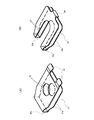
図20~図23は、本発明の第1実施形態の第9例を示している。本例の場合には、車体側ブラケット11eの基板部25に形成する係止除肉部を、この基板部25の前端縁の幅方向中央部に開口する係止切り欠き44bとしている。この係止切り欠き44bの後端部の平面形状に関しても、第1例と同様に、略V字形としている。そして、車体側ブラケット11eを構成する金属板の一部でコラム側ブラケット12cの上板部23aの後端縁に対向する部分を前下方に向け断面U字形に折り返すことにより形成した下側折り返し部45により、上板部23aの後端縁部を抱持している。また、この上板部23aの前端縁部から前方に延出した延出板部46を後上方に向け断面U字形に折り返すことにより形成した上側折り返し部47により、車体側ブラケット11eの基板部25の前後方向中間部で係止切り欠き44bの両側部分を抑え付けている。なお、延出板部46は、幅寸法がこの係止切り欠き44bの幅寸法よりも小さな基部48と、この基部48の先端部に設けられ、幅寸法がこの係止切り欠き44bの幅寸法よりも大きな抑え板部49を備えている。そして、基部48をこの係止切り欠き44b内に進入させた状態で、この抑え板部49の幅方向両端部分で、基板部25の上面を抑え付けている。
[Ninth Example of First Embodiment]
20 to 23 show a ninth example of the first embodiment of the present invention. In the case of this example, the locking thinning portion formed on the board portion 25 of the vehicle body side bracket 11e is a locking notch 44b that opens at the center in the width direction of the front end edge of the board portion 25. As with the first example, the planar shape of the rear end portion of the locking notch 44b is substantially V-shaped. Then, a lower folded portion formed by folding a part of the metal plate constituting the vehicle body side bracket 11e facing the rear end edge of the upper plate portion 23a of the column side bracket 12c in a U-shaped cross section toward the front lower side. 45 holds the rear edge portion of the upper plate portion 23a. Further, the board portion 25 of the vehicle body side bracket 11e is formed by an upper folded portion 47 formed by folding an extended plate portion 46 extending forward from the front end edge portion of the upper plate portion 23a toward the rear upper side in a U-shaped cross section. The both sides of the locking notch 44b are held down at the middle part in the front-rear direction. The extension plate portion 46 is provided at the base 48 having a width dimension smaller than the width dimension of the locking notch 44b and the tip of the base 48, and the width dimension is a width dimension of the locking notch 44b. A larger holding plate portion 49 is provided. Then, the upper surface of the substrate portion 25 is held down by both end portions in the width direction of the holding plate portion 49 with the base portion 48 being inserted into the locking notch 44b.
本例の構造の場合には、下側折り返し部45により上板部23aの後端縁部を抱持するとともに、上側折り返し部47により基板部25の上面を抑え付けているため、車体側ブラケット11eに対するコラム側ブラケット12cの支持剛性を向上させることができる。また、下側折り返し部45に関しては、一次衝突時にコラム側ブラケット12cが後方に変位することを抑制する力を高める効果も有する。なお、二次衝突時の離脱荷重を低く抑えたまま、この支持剛性を高くするためには、これらの折り返し部45、47と相手面との間部分に、低摩擦材を介在させることが好ましい。この場合、この間部分に、片面または両面に低摩擦材製のコーティング層を設けた滑り板、あるいは低摩擦材製のフィルムを挟持する構造を採用することができる。その他の部分の構造および作用は、第7例と同様であるから、重複する説明は省略する。
In the case of the structure of this example, the rear end edge portion of the upper plate portion 23a is held by the lower folded portion 45 and the upper surface of the substrate portion 25 is suppressed by the upper folded portion 47, so that the vehicle body side bracket The support rigidity of the column side bracket 12c with respect to 11e can be improved. Further, the lower folded portion 45 also has an effect of increasing the force for suppressing the column side bracket 12c from being displaced rearward at the time of the primary collision. In order to increase the support rigidity while keeping the separation load at the time of the secondary collision low, it is preferable to interpose a low friction material between the folded portions 45 and 47 and the mating surface. . In this case, a structure in which a sliding plate provided with a coating layer made of a low friction material on one side or both sides, or a film made of a low friction material can be adopted in the intermediate portion. Since the structure and operation of the other parts are the same as in the seventh example, a duplicate description is omitted.
[第1実施形態の第10例]
図24~図25は、本発明の第1実施形態の第10例を示している。本例の場合には、係止除肉部である透孔27内の後端部に、スペーサ55を配置している。このスペーサ55は、銅系合金、高機能樹脂、含油メタルなどの滑りやすい材料により略矩形、あるいは、後端部が透孔27の後端部の平面形状に倣った略V字状となっている形状に造られたもので、車体側ブラケット11aの基板部25の厚さ寸法と同等もしくはそれ以下の厚さ寸法を有する。このスペーサ55は、両側縁部に部分円弧状の凸部を形成したり、あるいは前端両角部を4分の1円弧状に丸くするなどして、二次衝突に伴う前方への変位時に、透孔27の左右両内側縁に引っ掛からないようにしたりすることが好ましい。いずれにしても、スペーサ55の最大幅W55は、透孔27の内寸W27以下(W55≦W27)としている。このようなスペーサ55は、透孔27の後端部に配置した状態で、スライド部材28を構成する内側スライド素板52の、上下の滑り板部31bの間に挟持している。二次衝突時には、スペーサ55が透孔27に沿って前方に変位することで、コラム側ブラケット12bの前方への変位が円滑に行われるようにしている。その他の部分の構造および作用は、第1例と同様であるから、重複する図示並びに説明は省略する。
[Tenth example of the first embodiment]
24 to 25 show a tenth example of the first embodiment of the present invention. In the case of this example, a spacer 55 is arranged at the rear end portion in the through hole 27 which is a locking and thinning portion. The spacer 55 has a substantially rectangular shape made of a slippery material such as a copper-based alloy, a high-functional resin, or an oil-containing metal, or a substantially V-shaped rear end portion that follows the planar shape of the rear end portion of the through hole 27. It has a thickness dimension equal to or less than the thickness dimension of the substrate portion 25 of the vehicle body side bracket 11a. The spacer 55 is formed by forming partial arc-shaped convex portions on both side edges, or rounding the front end corners to a quarter arc shape, etc., during the forward displacement due to a secondary collision. It is preferable not to be caught on the left and right inner edges of the hole 27. In any case, the maximum width W 55 of the spacer 55 is set to be equal to or smaller than the inner dimension W 27 of the through hole 27 (W 55 ≦ W 27 ). Such a spacer 55 is sandwiched between the upper and lower sliding plate portions 31 b of the inner slide base plate 52 constituting the slide member 28 in a state of being arranged at the rear end portion of the through hole 27. At the time of the secondary collision, the spacer 55 is displaced forward along the through hole 27 so that the column side bracket 12b is smoothly displaced forward. Since the structure and operation of other parts are the same as in the first example, overlapping illustrations and descriptions are omitted.
[第2実施形態]
図26~図39は、本発明の第2実施形態の1例を示している。本例の場合、車体側ブラケット11fは、十分な強度および剛性を有する炭素鋼板などの金属板製の素材に、プレスによる打ち抜き加工、レーザカッタなどによる切断加工を施すことにより、平板状に形成されている。ただし、素材として厚さ寸法の小さなものを使用する代わりに、第1実施形態の各例と同様に、両側縁部および後端縁部を曲げ形成して剛性を確保することも可能である。
[Second Embodiment]
26 to 39 show an example of the second embodiment of the present invention. In the case of this example, the vehicle body side bracket 11f is formed in a flat plate shape by subjecting a material made of a metal plate such as a carbon steel plate having sufficient strength and rigidity to punching with a press or cutting with a laser cutter. ing. However, instead of using a material with a small thickness, it is also possible to ensure rigidity by bending both side edges and the rear edge as in the examples of the first embodiment.
いずれにしても、本例に組み込む、車体側ブラケット11fの幅寸法は、前半部で狭く、後半部で広くしている。そして、この車体側ブラケット11fの幅方向中央部に、係止除肉部である係止切り欠き56を、この車体側ブラケット11fの前端縁中央部にのみ開口する状態で形成している。この係止切り欠き56の前後方向の長さ寸法は、十分に長くして、二次衝突が進行した状態、すなわち、二次衝突時の衝撃エネルギでは、ステアリングホイールがそれ以上前方に変位しない状態でも、車体側ブラケット11fによるコラム側ブラケット12dの支持力が喪失しないようにしている。なお、本例においても、係止除肉部として、係止切り欠き56に代替して、車体側ブラケットの基板部の前端縁が開口しない透孔とすることも可能である。
In any case, the width dimension of the vehicle body side bracket 11f incorporated in this example is narrow in the front half and wide in the rear half. A locking notch 56, which is a locking thinning portion, is formed at the central portion in the width direction of the vehicle body side bracket 11f so as to open only at the central portion of the front end edge of the vehicle body side bracket 11f. The length of the locking notch 56 in the front-rear direction is sufficiently long so that the secondary collision has progressed, that is, the steering wheel is not displaced further forward by the impact energy at the time of the secondary collision. However, the support force of the column side bracket 12d by the vehicle body side bracket 11f is not lost. Also in this example, as the locking thinning portion, it is possible to replace the locking notch 56 with a through hole in which the front end edge of the base plate portion of the vehicle body side bracket does not open.
本発明の第2実施形態では、コラム側ブラケット12dは、車体側ブラケット11fに、二次衝突時に加わる衝撃荷重により前方への離脱を可能に支持するための構造として、以下のような構造を採用している。すなわち、下記の(1)~(3)の構成のうち、(1)、(2)のうちの少なくとも一方の構成に、(3)の構成を組み合わせた構造、もしくは、(1)~(3)の構成をすべて組み合わせた構造である。なお、本例では、(1)~(3)のすべての構成を組み合わせた構造を採用している。
In the second embodiment of the present invention, the column side bracket 12d employs the following structure as a structure for supporting the vehicle body side bracket 11f so that it can be detached forward by an impact load applied during a secondary collision. is doing. That is, among the following configurations (1) to (3), at least one of the configurations (1) and (2) is combined with the configuration (3), or (1) to (3 ) Is a combination of all the configurations. In this example, a structure in which all the configurations (1) to (3) are combined is adopted.
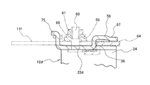
(1)前記車体側ブラケット11fの係止除肉部である係止切り欠き56の後端縁のうち少なくとも幅方向中央部に、先端縁を前方に向けた状態で下方に曲げ形成した下側押圧板部57により、コラム側ブラケット12dの上板部23bの幅方向中央部の下面を上方に押圧し、この上板部23bの上面を車体側ブラケット11fの下面に押し付ける。
(1) A lower side formed by bending downward at a central portion at least in the width direction among the rear end edges of the locking notches 56 which are locking thinning portions of the vehicle body side bracket 11f with the front end edge facing forward. The lower surface of the central portion in the width direction of the upper plate portion 23b of the column side bracket 12d is pressed upward by the pressing plate portion 57, and the upper surface of the upper plate portion 23b is pressed against the lower surface of the vehicle body side bracket 11f.
(2)上板部23bの前部以外の部分(後半部)の幅方向中央部に、先端縁を後方に向けた状態で上方に曲げ形成した上側押圧板部58により、車体側ブラケット11fの幅方向中央部の上面を下方に押圧し、この車体側ブラケット11fの下面を上板部23bの上面に押し付ける。
(2) The vehicle body side bracket 11f is mounted on the vehicle body side bracket 11f by an upper pressing plate portion 58 formed by bending upward in a state where the front end edge is directed rearward at the center portion in the width direction of the portion (second half portion) other than the front portion of the upper plate portion 23b. The upper surface of the central portion in the width direction is pressed downward, and the lower surface of the vehicle body side bracket 11f is pressed against the upper surface of the upper plate portion 23b.
(3)車体側ブラケット11fの上面に、係止除肉部である係止切り欠き56の左右両側部分に掛け渡された抑え板59を設け、この抑え板59とコラム側ブラケット12dの上板部23bとを結合部材であるボルト60とナット61とで結合することにより、抑え板59と上板部23bとの間で、車体側ブラケット11fのうちの、係止切り欠き56の左右両側部分を挟持する。
(3) On the upper surface of the vehicle body side bracket 11f, there are provided holding plates 59 that are stretched over the left and right side portions of the locking notches 56 that are the locking thinning portions, and the upper plate of the holding plate 59 and the column side bracket 12d. By connecting the portion 23b with a bolt 60 and a nut 61, which are connecting members, between the holding plate 59 and the upper plate portion 23b, left and right side portions of the locking notch 56 in the vehicle body side bracket 11f. Pinch.
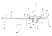
まず、構成(1)について、図26~図32を参照しつつ説明する。この構成(1)は、車体側ブラケット11fの後部の幅方向中央部で、係止切り欠き56の後端縁の幅方向中央部に、下側押圧板部57の基端縁を連続させている。この下側押圧板部57は、車体側ブラケット11fを構成する金属板の一部で、係止切り欠き56の後端部に位置する部分を残すことにより設けた、前端縁を他の部分と連結されていない自由端とした突出板部を曲げ形成することにより、得られる。すなわち、この突出板部の基端部(後端部)を車体側ブラケット11fの本体部分に対し、下方に向け直角に折り曲げて下側連結板部62としている。さらに、突出板部の中間部基端寄り部分を前方に向け、この下側連結板部62に対し直角に折り曲げて、この突出板部の中間部ないし先端部を、車体側ブラケット11fの本体部分とほぼ平行な下側弾性押圧板部63としている。
First, the configuration (1) will be described with reference to FIGS. This configuration (1) is such that the base end edge of the lower pressing plate portion 57 is continuous with the center portion in the width direction of the rear end edge of the locking notch 56 at the center portion in the width direction of the rear portion of the vehicle body side bracket 11f. Yes. The lower pressing plate portion 57 is a part of the metal plate constituting the vehicle body side bracket 11f, and the front end edge provided by leaving the portion located at the rear end portion of the locking notch 56 is different from the other portion. It can be obtained by bending a protruding plate portion that is a free end that is not connected. That is, the base end portion (rear end portion) of the protruding plate portion is bent at a right angle downward with respect to the main body portion of the vehicle body side bracket 11 f to form the lower connecting plate portion 62. Further, the portion near the proximal end of the intermediate portion of the protruding plate portion is directed forward and bent at a right angle with respect to the lower connecting plate portion 62, and the intermediate portion or the distal end portion of the protruding plate portion is the main body portion of the vehicle body side bracket 11f. The lower elastic pressing plate portion 63 is substantially parallel to the lower side.
そして、この下側弾性押圧板部63の先端部上面を、スライド部材である滑り板64の一部を介して、コラム側ブラケット12dを構成する上板部23bの幅方向中央部の下面に、弾性的に押し付けている。そして、この上板部23bの幅方向両端部を、車体側ブラケット11fのうちで係止切り欠き56の左右両側に位置する部分の下面に向け弾性的に押し付けて、コラム側ブラケット12dの前後方向中間部を車体側ブラケット11fに対し、二次衝突時に加わる衝撃荷重により前方への離脱を可能に支持している。
Then, the upper surface of the tip end portion of the lower elastic pressing plate portion 63 is connected to the lower surface of the central portion in the width direction of the upper plate portion 23b constituting the column side bracket 12d via a part of the sliding plate 64 which is a sliding member. It is pressed elastically. Then, both end portions in the width direction of the upper plate portion 23b are elastically pressed toward the lower surfaces of the portions located on the left and right sides of the locking notch 56 in the vehicle body side bracket 11f, and the longitudinal direction of the column side bracket 12d. The intermediate portion is supported to the vehicle body side bracket 11f so as to be able to be detached forward by an impact load applied during a secondary collision.
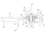
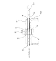
次に、構成(2)について、図26~図28、図33~図36を参照しつつ説明する。この構成(2)は、コラム側ブラケット12dを構成する上板部23bの幅方向中央部の後半部に、先端縁を後方に向けた状態で上方に曲げ形成した上側押圧板部58を設けることで、形成される。本例の場合には、上板部23dの中央寄り部分で幅方向に離隔した2箇所位置に、それぞれがこの上板部23dの後端縁に開口したスリット状の切り欠き65を、互いに平行に形成している。そして、これらの切り欠き65に幅方向両側を挟まれた矩形状板部の基端部(前端部)を上板部23dの本体部分に対し、上方に向け直角に折り曲げて、上側連結板部66としている。さらに、矩形状板部の中間部基端寄り部分を後方に向け、この上側連結板部66に対し直角に折り曲げて、この矩形状板部の中間部ないし先端部を、上板部23bの本体部分とほぼ平行な上側弾性押圧板部67としている。
Next, the configuration (2) will be described with reference to FIGS. 26 to 28 and FIGS. 33 to 36. In this configuration (2), an upper pressing plate portion 58 formed by bending upward with the tip edge directed rearward is provided in the rear half of the central portion in the width direction of the upper plate portion 23b constituting the column side bracket 12d. And formed. In the case of this example, slit-like notches 65 opened at the rear edge of the upper plate portion 23d are parallel to each other at two positions separated in the width direction at the central portion of the upper plate portion 23d. Is formed. Then, the base end portion (front end portion) of the rectangular plate portion sandwiched by the notches 65 on both sides in the width direction is bent at a right angle upward with respect to the main body portion of the upper plate portion 23d, and the upper connecting plate portion 66. Further, the portion near the proximal end of the intermediate portion of the rectangular plate portion is directed rearward and bent at a right angle with respect to the upper connecting plate portion 66, and the intermediate portion or the distal end portion of the rectangular plate portion is the main body of the upper plate portion 23b. The upper elastic pressing plate portion 67 is substantially parallel to the portion.
そして、この上側弾性押圧板部67の先端部下面を、スライド部材である滑り板64の他の部分を介して、車体側ブラケット11fの本体部分の後端部の幅方向中央部の上面に、弾性的に当接させている。本例の場合には、上側弾性押圧板部67の先端部(後端部)をかしめ付けて、少し下方に変形させ、この変形部を、車体側ブラケット11fの一部上面に、滑り板64を介して押し付けている。そして、上側弾性押圧板部67により、この車体側ブラケット11fの後端部を、コラム側ブラケット12dを構成する上板部23dのうちで切り欠き65の両側に存在する幅方向2箇所位置の上面に向け弾性的に押し付けて、コラム側ブラケット12dの後端部を車体側ブラケット11fに対し、二次衝突時に加わる衝撃荷重により前方への離脱を可能に支持している。なお、構成(1)および(2)の下側押圧板部57および上側押圧板部58はいずれも、車体側ブラケット11fおよびコラム側ブラケット12dの幅方向中央部に設置して、その幅方向中心を互いに一致させている。
Then, the lower surface of the front end portion of the upper elastic pressing plate portion 67 is placed on the upper surface of the central portion in the width direction of the rear end portion of the body portion of the vehicle body side bracket 11f via the other portion of the sliding plate 64 which is a sliding member. It is made to contact elastically. In the case of this example, the front end portion (rear end portion) of the upper elastic pressing plate portion 67 is caulked and deformed slightly downward, and this deformed portion is formed on a partial upper surface of the vehicle body side bracket 11f on the sliding plate 64. Is pressed through. Then, the upper elastic pressing plate portion 67 causes the rear end portion of the vehicle body side bracket 11f to have an upper surface at two positions in the width direction existing on both sides of the notch 65 in the upper plate portion 23d constituting the column side bracket 12d. The rear end portion of the column side bracket 12d is supported to the vehicle body side bracket 11f so as to be able to be separated forward by an impact load applied during a secondary collision. The lower pressing plate portion 57 and the upper pressing plate portion 58 of the configurations (1) and (2) are both installed at the center in the width direction of the vehicle body side bracket 11f and the column side bracket 12d, and the center in the width direction. Are matched with each other.
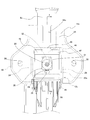
さらに、構成(3)について、図26~図28を参照しつつ説明する。車体側ブラケット11fの上面に抑え板59を、係止切り欠き56の両側部分に掛け渡す状態で設置している。この抑え板59は、ステンレスのばね鋼板、亜鉛メッキ鋼板、燐青銅板のような、ばね性を有し、および/または、両端部下面が当接する滑り板64との間で錆付かない材料を使用することが好ましい。そして、コラム側ブラケット12dの上板部23bの前半部の幅方向中央部に形成した通孔、並びに、係止切り欠き56を下方から挿通したボルト60の先端部(上端部)に螺合したナット61により、抑え板59の幅方向中央部の上面を、ワッシャ68を介して下方に押圧している。そして、この抑え板59の幅方向両端部の下面を、車体側ブラケット11fのうちで、前記係止切り欠き56の両側部分の上面に、次述する滑り板64の他の部分を介して、弾性的に当接させている。
Further, the configuration (3) will be described with reference to FIGS. A restraining plate 59 is installed on the upper surface of the vehicle body side bracket 11 f so as to be hung over both side portions of the locking notch 56. The restraining plate 59 is made of a material that has a spring property and / or does not rust between the sliding plate 64 with which the lower surfaces of both ends abut, such as a stainless spring steel plate, a galvanized steel plate, and a phosphor bronze plate. It is preferable to use it. Then, the through hole formed in the central portion in the width direction of the front half of the upper plate portion 23b of the column side bracket 12d and the front end portion (upper end portion) of the bolt 60 inserted through the locking notch 56 from below are screwed. The upper surface of the central portion in the width direction of the pressing plate 59 is pressed downward by the nut 61 via the washer 68. And, the lower surface of both ends in the width direction of the holding plate 59 is connected to the upper surface of both side portions of the locking notch 56 in the vehicle body side bracket 11f via other portions of the sliding plate 64 described below. It is made to contact elastically.
構成(1)~(3)により得られる結合構造はいずれも、摩擦力により、通常時に車体側ブラケット11fに対してコラム側ブラケット12dが前方に変位することを阻止し、二次衝突時には、摩擦力に抗して、このコラム側ブラケット12dを前方に変位させることを可能としている。二次衝突発生の瞬間に、コラム側ブラケット12dおよびこのコラム側ブラケット12dに支持されたステアリングホイール1の前方への変位が円滑に行われるようにするためには、この摩擦力(静止摩擦力)を低く抑えることが好ましい。ただし、この摩擦力を低く抑えるために、構成(1)~(3)により得られる結合構造に存在する当接面の面圧を低くすることは、車体側ブラケット11fに対するコラム側ブラケット12dの支持剛性が低くなり、ステアリングホイール1の操作感が低下するため、採用できない。そこで本例の場合には、構成(1)~(3)により得られる結合構造部分に、スライド部材である滑り板64を介在させて、この摩擦力を低く抑えるようにしている。
In any of the coupling structures obtained by the configurations (1) to (3), the frictional force prevents the column side bracket 12d from being displaced forward with respect to the vehicle body side bracket 11f during normal operation. This column side bracket 12d can be displaced forward against the force. In order to ensure that the column side bracket 12d and the steering wheel 1 supported by the column side bracket 12d are smoothly displaced forward at the moment of occurrence of the secondary collision, this frictional force (static frictional force) is used. Is preferably kept low. However, in order to keep the frictional force low, reducing the surface pressure of the contact surface existing in the coupling structure obtained by the configurations (1) to (3) is to support the column side bracket 12d with respect to the vehicle body side bracket 11f. Since the rigidity is lowered and the operational feeling of the steering wheel 1 is lowered, it cannot be adopted. Therefore, in the case of this example, a sliding plate 64, which is a sliding member, is interposed in the coupling structure portion obtained by the configurations (1) to (3) so as to keep this frictional force low.
スライド部材である滑り板64は、ステンレス鋼板などの金属薄板を曲げ形成して得られる。この金属薄板の片面には、ポリ四フッ化エチレン樹脂、ポリアミド樹脂、二硫化モリブデンなどの低摩擦材のコーティング層を被覆している。この滑り板64の形状について、図37~図40を参照しつつ説明する。この滑り板64は、後端部に設けた連結板部69と、この連結板部69の上下両端縁からそれぞれ前方に向け直角に折れ曲がって伸長する、それぞれが滑り板部である上側板部70および下側板部71を備える。コーティング層は、連結板部69の後面と、上側板部70の上面と、下側板部71の下面とに存在する。
The sliding plate 64 which is a sliding member is obtained by bending a thin metal plate such as a stainless steel plate. One surface of the metal thin plate is coated with a coating layer of a low friction material such as polytetrafluoroethylene resin, polyamide resin, molybdenum disulfide. The shape of the sliding plate 64 will be described with reference to FIGS. The sliding plate 64 includes a connecting plate portion 69 provided at a rear end portion, and an upper plate portion 70 that is bent at a right angle toward the front from the upper and lower end edges of the connecting plate portion 69 and extends. And a lower plate portion 71. The coating layer is present on the rear surface of the connecting plate portion 69, the upper surface of the upper plate portion 70, and the lower surface of the lower plate portion 71.
上側板部70のうちで、ステアリングコラム用支持装置への組み付け状態で、車体側ブラケット11fの係止切り欠き56に整合する部分には、前方に開口した切り欠きを設けている。したがって、上側板部70は、後端部を除く部分が二股形状となっている。一方、下側板部71に関しても、係止切り欠き56に整合する部分に前方に開口した切り欠きを設けて、後端部を除く部分を二股形状としている。ただし、下側板部71に関しては、切り欠きの後端部の幅方向中央部で、ステアリングコラム用支持装置への組み付け状態で下側押圧板部57の上側に位置する部分に、前方に突出した突出板部72を形成している。また、この突出板部72の先端部(前端部)に、コーティング層を被覆していない面を内側にして、突出板部72の先端部を上側に向けて180度密に折り返された折り返し部73を設けている。したがって、突出板部72の先端部に関しては、下面だけでなく、上面にも、コーティング層が存在する。
A portion of the upper plate portion 70 that is aligned with the locking notch 56 of the vehicle body side bracket 11f in the assembled state to the steering column support device is provided with a notch that opens forward. Therefore, the upper plate portion 70 has a bifurcated shape except for the rear end portion. On the other hand, the lower plate portion 71 is also provided with a notch opened forward at a portion aligned with the locking notch 56, and the portion excluding the rear end portion has a bifurcated shape. However, with respect to the lower plate portion 71, it protrudes forward at the center portion in the width direction of the rear end portion of the notch, at the portion located above the lower pressing plate portion 57 in the assembled state to the steering column support device. A protruding plate portion 72 is formed. In addition, a folded portion that is folded back 180 degrees densely with the front end portion (front end portion) of the protruding plate portion 72 facing inward with the surface not coated with the coating layer facing upward. 73 is provided. Therefore, the coating layer is present not only on the lower surface but also on the upper surface of the tip portion of the protruding plate portion 72.
この滑り板64は、ステアリングコラム用支持装置への組み付け状態で、図26~図28に示すように、上側板部70の前端部が、車体側ブラケット11fの上面と、抑え板59の両端部下面との間に挟持される。この状態で、コーティング層は、この抑え板59の両端部下面に当接する。一方、下側板部71のうちで、突出板部72以外の部分は、車体側ブラケット11fの下面と、コラム側ブラケット12dを構成する上板部23bの上面との間に挟持される。この状態で、コーティング層は、この上板部23bの上面に当接する。さらに、突出板部72の先端部に設けた折り返し部73は、上板部23bの下面と、車体側ブラケット11fに設けた下側押圧板部57の上面との間に挟持される。この状態で、コーティング層は、この下側押圧板部57の上面だけでなく、上板部23bの下面にも当接する。
When the sliding plate 64 is assembled to the steering column support device, as shown in FIGS. 26 to 28, the front end portion of the upper plate portion 70 is connected to the upper surface of the vehicle body side bracket 11f and both end portions of the holding plate 59. It is sandwiched between the lower surface. In this state, the coating layer contacts the lower surfaces of both end portions of the holding plate 59. On the other hand, in the lower plate portion 71, the portion other than the protruding plate portion 72 is sandwiched between the lower surface of the vehicle body side bracket 11f and the upper surface of the upper plate portion 23b constituting the column side bracket 12d. In this state, the coating layer contacts the upper surface of the upper plate portion 23b. Further, the folded-back portion 73 provided at the distal end portion of the protruding plate portion 72 is sandwiched between the lower surface of the upper plate portion 23b and the upper surface of the lower pressing plate portion 57 provided in the vehicle body side bracket 11f. In this state, the coating layer contacts not only the upper surface of the lower pressing plate portion 57 but also the lower surface of the upper plate portion 23b.
滑り板64を上述のように組み付けるために、図40(B)に示す、突出板部72の片側縁と、下側板部71に形成した切り欠きの内側縁との間隔Dは、図32に示す、下側押圧板部57の下側連結板部62の基部の幅W以上として(D≧W)、この下側押圧板部57を、図26および図27に示すように、下側板部71に形成した切り欠きの奥部にまで進入させられるようにしている。滑り板64を図26~図28に示すように、ステアリングコラム用支持装置に組み付けた状態で、この滑り板64は、車体側ブラケット11fの後端縁と連結板部69との係合により、前方に変位することが阻止される。すなわち、本例では、二次衝突時にも滑り板64は、そのままの位置に止まる。一方、二次衝突時に前方に変位する、コラム側ブラケット12dおよび抑え板59と、滑り板64との当接部には、いずれもコーティング層が存在する。したがって、二次衝突時にコラム側ブラケット12dが前方に変位するために要する離脱荷重を、低く、かつ安定させることが可能となる。
In order to assemble the sliding plate 64 as described above, the distance D between the one side edge of the protruding plate portion 72 and the inner edge of the notch formed in the lower plate portion 71 shown in FIG. As shown in FIG. 26 and FIG. 27, the lower pressing plate portion 57 is set to be equal to or larger than the width W of the base portion of the lower connecting plate portion 62 of the lower pressing plate portion 57. It is made to approach to the back part of the notch formed in 71. FIG. As shown in FIGS. 26 to 28, when the sliding plate 64 is assembled to the steering column support device, the sliding plate 64 is engaged with the rear end edge of the vehicle body side bracket 11f and the connecting plate portion 69. Displacement forward is prevented. That is, in this example, the sliding plate 64 remains in the same position even during a secondary collision. On the other hand, a coating layer is present in all of the contact portions between the column side bracket 12d and the holding plate 59 and the sliding plate 64 that are displaced forward during a secondary collision. Therefore, the separation load required for the column side bracket 12d to move forward at the time of the secondary collision can be reduced and stabilized.
本例の場合にも、ステアリングホイール1に衝突した運転者の身体に加わる衝撃を十分に吸収するために、コラム側ブラケット12dと、車体側ブラケット11fあるいは車体もしくは車体側に固定され、二次衝突時にも前方に変位することがない部分との間に、塑性変形しつつコラム側ブラケット12dの前方への変位を許容する、エネルギ吸収部材74を設けている。このため、このコラム側ブラケット12dを構成する上板部23bの前端縁の幅方向中央部に変位側係止部75を、このコラム側ブラケット12dを構成する金属板を上方に曲げ起こす状態で形成している。そして、変位側係止部75と、車体側ブラケット11fなどとの間に、伸長方向に塑性変形することにより、二次衝突に伴ってコラム側ブラケット12dに加わった衝撃エネルギを吸収する、エネルギ吸収部材74を設けている。なお、車体側ブラケット11fなどの車体側におけるエネルギ吸収部材74の係止構造は、公知であるため、その説明は省略する。また、エネルギ吸収部材の構造は図示のものに限定されず、ステアリングコラムまたはこのステアリングコラムとともに前方に変位する部分と、車体側ブラケットまたは車体もしくは車体側に固定された部分との間に設けることが可能であり、塑性変形することで衝撃荷重を吸収可能の構造を有する任意のエネルギ吸収部材を採用することも可能である。
Also in this example, in order to sufficiently absorb the impact applied to the driver's body colliding with the steering wheel 1, it is fixed to the column side bracket 12d and the vehicle body side bracket 11f or the vehicle body or the vehicle body side, and the secondary collision. An energy absorbing member 74 that allows the column side bracket 12d to be displaced forward while being plastically deformed is provided between the portion that does not displace forward at times. Therefore, the displacement side locking portion 75 is formed at the center in the width direction of the front edge of the upper plate portion 23b constituting the column side bracket 12d, and the metal plate constituting the column side bracket 12d is bent upward. is doing. Then, the energy absorption that absorbs the impact energy applied to the column side bracket 12d due to the secondary collision by plastically deforming in the extension direction between the displacement side locking portion 75 and the vehicle body side bracket 11f or the like. A member 74 is provided. In addition, since the latching structure of the energy absorption member 74 in vehicle body side, such as the vehicle body side bracket 11f, is well-known, the description is abbreviate | omitted. In addition, the structure of the energy absorbing member is not limited to that shown in the figure, and may be provided between the steering column or a portion displaced forward together with the steering column, and the vehicle body side bracket or the vehicle body or the portion fixed to the vehicle body side. It is possible to employ any energy absorbing member having a structure capable of absorbing an impact load by plastic deformation.
第2実施態様のステアリングコラム用支持装置を組み立てる場合には、まず、下側押圧板部57によりコラム側ブラケット12dの上板部23bの幅方向中央部の下面を上方に押圧する、および/または、上側押圧板部58により車体側ブラケット11fの幅方向中央部の上面を下方に押圧する。この結果、この車体側ブラケット11fとコラム側ブラケット12dとが、互いに上下方向に押し付け合わされて、車体側ブラケット11fに対して、コラム側ブラケット12dの上板部23bが、結合支持される。この状態では、未だ抑え板29は組み付けられていない。そこで、この状態で、車体側ブラケット11fに対してコラム側ブラケット12dが前後方向に変位し始める荷重である、中間段階の離脱荷重を測定する。この離脱荷重の測定は、車体側ブラケット11fを動かないように支持した状態で、コラム側ブラケット12dを前方に押しあるいは引っ張り、このコラム側ブラケット12dがわずかに変位する瞬間の荷重を測定することで行う。このコラムブラケット12dがわずかに変位した瞬間に、このコラム側ブラケット12dに加えている力を解除して、このコラム側ブラケット12dがそれ以上前方に変位しないようにする。必要に応じて、変位分を元に戻してもよい。このようにして、構成(1)(2)に基づく離脱荷重を測定するが、この状態での離脱荷重は、組み立て完了後の状態でステアリングコラム用支持装置に必要とされる適切な離脱荷重である適正離脱荷重よりも小さくなるように、下側押圧板部57および上側押圧板部58の押圧力を調節しておく。
When assembling the steering column support device of the second embodiment, first, the lower pressing plate portion 57 presses the lower surface of the central portion in the width direction of the upper plate portion 23b of the column side bracket 12d upward, and / or Then, the upper surface of the central portion in the width direction of the vehicle body side bracket 11f is pressed downward by the upper pressing plate portion 58. As a result, the vehicle body side bracket 11f and the column side bracket 12d are pressed against each other in the vertical direction, and the upper plate portion 23b of the column side bracket 12d is coupled and supported to the vehicle body side bracket 11f. In this state, the holding plate 29 is not yet assembled. Therefore, in this state, an intermediate separation load, which is a load at which the column side bracket 12d starts to be displaced in the front-rear direction with respect to the vehicle body side bracket 11f, is measured. The separation load is measured by pushing or pulling the column side bracket 12d forward while the vehicle body side bracket 11f is supported so as not to move, and measuring the load at the moment when the column side bracket 12d is slightly displaced. Do. At the moment when the column bracket 12d is slightly displaced, the force applied to the column side bracket 12d is released so that the column side bracket 12d is not displaced further forward. If necessary, the displacement may be restored. Thus, the detachment load based on the configurations (1) and (2) is measured. The detachment load in this state is an appropriate detachment load required for the steering column support device after the assembly is completed. The pressing force of the lower pressing plate portion 57 and the upper pressing plate portion 58 is adjusted so as to be smaller than a certain appropriate separation load.
構成(1)(2)に基づく離脱荷重を測定してから、この中間段階での離脱荷重と、前記適正離脱荷重との差を求める。その後、抑え板59とコラム側ブラケット12dの上板部23bとを、結合部材であるボルト60とナット61とにより、これらの荷重の差に見合う強度で結合する。この強度は、構成(1)(2)に基づく離脱荷重の測定値に基づいて調節可能であるし、この締め付けトルクと、前記離脱荷重の増加分との関係は、あらかじめ実験により求めておくことができる。また、抑え板59を弾性金属板製とすることにより、結合部材による締め付けトルクの値が多少目標値からずれても、前記離脱荷重の増加分が大きく変動することはない。そこで、ボルト60とナット61とを所定のトルクにより締め付ければ、前記離脱荷重を適切に増加させて、前記適正離脱荷重を、精度よく得ることができる。なお、本例では、ボルト60は、コラム側ブラケット12dの上板部23b側からスライド部材である滑り板64を上下方向に挿通するように配置される。そして、滑り板64を挿通したボルト60の上端部であって抑え板59の上面から突出した部分に、ナット61を螺合する。よって、本例では、このナット61が上端側に備えられた抑え部分に相当し、このナット61の下面とコラム側ブラケット12dの上板部23bの上面との間に、車体側ブラケット1fの一部が、1対の滑り板部である上側板部70および下側板部71、さらには抑え板59、ワッシャ69を介して、挟持される。
Measure the separation load based on the configurations (1) and (2), and then determine the difference between the separation load at this intermediate stage and the appropriate separation load. Thereafter, the holding plate 59 and the upper plate portion 23b of the column side bracket 12d are coupled with a bolt 60 and a nut 61, which are coupling members, with a strength corresponding to the difference between these loads. This strength can be adjusted based on the measurement value of the separation load based on the configurations (1) and (2), and the relationship between the tightening torque and the increase in the separation load should be obtained by experiments in advance. Can do. In addition, since the holding plate 59 is made of an elastic metal plate, even if the value of the tightening torque by the coupling member slightly deviates from the target value, the increase in the separation load does not vary greatly. Therefore, if the bolt 60 and the nut 61 are tightened with a predetermined torque, the separation load can be appropriately increased and the proper separation load can be obtained with high accuracy. In this example, the bolt 60 is disposed so as to be inserted in the vertical direction through the sliding plate 64 that is a sliding member from the upper plate portion 23b side of the column side bracket 12d. Then, the nut 61 is screwed into the upper end portion of the bolt 60 inserted through the sliding plate 64 and protruding from the upper surface of the holding plate 59. Therefore, in this example, the nut 61 corresponds to a holding portion provided on the upper end side, and a part of the vehicle body side bracket 1f is provided between the lower surface of the nut 61 and the upper surface of the upper plate portion 23b of the column side bracket 12d. Are sandwiched via an upper plate portion 70 and a lower plate portion 71 which are a pair of sliding plate portions, and further, a holding plate 59 and a washer 69.
このような本例のステアリングコラム用支持装置では、二次衝突時に、コラム側ブラケット12dの上板部23bおよび抑え板59が、車体側ブラケット11fに対し、前記適正離脱荷重に抗して前方に変位し始める。そして、この変位に伴ってエネルギ吸収部材74を塑性変形させ、運転者の身体からコラム側ブラケット12dに伝わった衝撃エネルギを吸収する。
In such a steering column support device of this example, the upper plate portion 23b and the holding plate 59 of the column side bracket 12d are moved forward against the appropriate separation load with respect to the vehicle body side bracket 11f at the time of a secondary collision. Start to displace. And with this displacement, the energy absorbing member 74 is plastically deformed to absorb the impact energy transmitted from the driver's body to the column side bracket 12d.
なお、係止切り欠き56の前後方向に関する長さは、二次衝突が進行した状態、すなわち、二次衝突に伴って運転者の身体からステアリングホイールに加わった衝撃エネルギによっては、それ以上ステアリングコラム6が前方に変位しなくなった状態でも、抑え板59が係止切り欠き56から前方に抜け出し切らないだけの長さを確保している。すなわち、二次衝突時に、ステアリングコラム6およびコラム側ブラケット12dとともに抑え板59が前方に変位した状態でも、抑え板59の幅方向両端部のうちの少なくとも後端部が車体側ブラケット11fの前端部の上側に位置して、抑え板59が脱落することを防止できるように、車体側ブラケット11fの前後方向寸法を確保している。
Note that the length of the locking notch 56 in the front-rear direction depends on the state in which the secondary collision has progressed, that is, depending on the impact energy applied to the steering wheel from the driver's body due to the secondary collision. Even in a state where 6 is no longer displaced forward, the length enough to prevent the holding plate 59 from slipping forward from the locking notch 56 is secured. That is, at the time of the secondary collision, even when the holding plate 59 is displaced forward together with the steering column 6 and the column side bracket 12d, at least the rear end portion of the both ends in the width direction of the holding plate 59 is the front end portion of the vehicle body side bracket 11f. The front-rear direction dimension of the vehicle body side bracket 11f is secured so that the holding plate 59 can be prevented from falling off.
本発明のいずれの実施態様を実施する場合にも、結合部材としては、結合部材による締め付けトルクの調節が容易であることから、ボルトとナットとが適切である。ただし、この締め付けトルクを調節できる限りにおいて、リベットを含む、その他の結合部材を使用することも可能である。さらに、第2実施形態では、車体側ブラケットとコラム側ブラケットとの結合構造を、車体側ブラケットの幅方向両側2箇所位置に形成した1対の通孔26の間にある部分の中央部に1箇所だけ設けているが、この車体側ブラケットと車体との結合固定部である、左右1対の通孔26の間にある部分であれば、複数箇所に設けることもできる。
In any embodiment of the present invention, a bolt and a nut are appropriate as the coupling member because the tightening torque can be easily adjusted by the coupling member. However, other coupling members including rivets can be used as long as the tightening torque can be adjusted. Further, in the second embodiment, the connecting structure of the vehicle body side bracket and the column side bracket is 1 at the center of the portion between the pair of through holes 26 formed at two positions on both sides in the width direction of the vehicle body side bracket. Although only a portion is provided, it can be provided at a plurality of locations as long as it is a portion between the pair of left and right through holes 26 that is a coupling and fixing portion between the vehicle body side bracket and the vehicle body.