JP5267528B2 - Shock absorbing steering device - Google Patents

Shock absorbing steering device Download PDF

Info

Publication number
JP5267528B2
JP5267528B2 JP2010215332A JP2010215332A JP5267528B2 JP 5267528 B2 JP5267528 B2 JP 5267528B2 JP 2010215332 A JP2010215332 A JP 2010215332A JP 2010215332 A JP2010215332 A JP 2010215332A JP 5267528 B2 JP5267528 B2 JP 5267528B2
Authority
JP
Japan
Prior art keywords
column
vehicle body
steering
plate portion
support bracket
Prior art date
Legal status (The legal status is an assumption and is not a legal conclusion. Google has not performed a legal analysis and makes no representation as to the accuracy of the status listed.)
Expired - Fee Related
Application number
JP2010215332A
Other languages
Japanese (ja)
Other versions
JP2012066779A (en
Inventor
恒 山本
康久 山田
伸治 岡田
Current Assignee (The listed assignees may be inaccurate. Google has not performed a legal analysis and makes no representation or warranty as to the accuracy of the list.)
NSK Ltd
Original Assignee
NSK Ltd
Priority date (The priority date is an assumption and is not a legal conclusion. Google has not performed a legal analysis and makes no representation as to the accuracy of the date listed.)
Filing date
Publication date
Application filed by NSK Ltd filed Critical NSK Ltd
Priority to JP2010215332A priority Critical patent/JP5267528B2/en
Publication of JP2012066779A publication Critical patent/JP2012066779A/en
Application granted granted Critical
Publication of JP5267528B2 publication Critical patent/JP5267528B2/en
Expired - Fee Related legal-status Critical Current
Anticipated expiration legal-status Critical

Links

Images

Landscapes

  • Steering Controls (AREA)

Abstract

<P>PROBLEM TO BE SOLVED: To provide structure enhancing protection of a driver, by stabilizing energy absorption performance. <P>SOLUTION: A steering column 6b can be contracted based on an impact load in a compression direction, by friction-engagement of a front part of an outer column 13a and a rear part of an inner column 14a. Alternatively, an energy absorbing member 39 is disposed between a support bracket 10a supporting the outer column 13a to be able to elevating, and a body-side bracket fixed to a vehicle body. In a secondary collision, the energy absorbing member 39 allows the steering wheel to be deformed forward together with the outer column 13a, while the energy absorbing member 39 is plastically deformed. By the design of the energy absorbing member 39, an absorption property of impact energy in the secondary collision is adjustable to solve the problem. <P>COPYRIGHT: (C)2012,JPO&amp;INPIT

Description

この発明は、衝突事故の際に運転者の身体からステアリングホイールに加わった衝撃エネルギを吸収しつつこのステアリングホイールの前方への変位を可能とする、衝撃吸収式ステアリング装置の改良に関する。具体的には、衝突事故の際のエネルギ吸収特性を向上させる事により、運転者の保護充実を図れる構造を実現するものである。   The present invention relates to an improvement in an impact absorption type steering device that allows the steering wheel to be displaced forward while absorbing impact energy applied to the steering wheel from the body of the driver in the event of a collision. Specifically, a structure capable of enhancing the protection of the driver is realized by improving the energy absorption characteristics in the event of a collision.

自動車用ステアリング装置は、図18に示す様に構成して、ステアリングホイール1の回転をステアリングギヤユニット2の入力軸3に伝達し、この入力軸3の回転に伴って左右1対のタイロッド4、4を押し引きして、前車輪に舵角を付与する様にしている。前記ステアリングホイール1は、ステアリングシャフト5の後端部に支持固定されており、このステアリングシャフト5は、円筒状のステアリングコラム6を軸方向に挿通した状態で、このステアリングコラム6に回転自在に支持されている。又、前記ステアリングシャフト5の前端部は、自在継手7を介して中間シャフト8の後端部に接続し、この中間シャフト8の前端部を、別の自在継手9を介して、前記入力軸3に接続している。   The automobile steering device is configured as shown in FIG. 18, and transmits the rotation of the steering wheel 1 to the input shaft 3 of the steering gear unit 2, and a pair of left and right tie rods 4 as the input shaft 3 rotates. 4 is pushed and pulled to give a steering angle to the front wheels. The steering wheel 1 is supported and fixed to the rear end portion of the steering shaft 5, and the steering shaft 5 is rotatably supported by the steering column 6 with the cylindrical steering column 6 inserted in the axial direction. Has been. Further, the front end portion of the steering shaft 5 is connected to the rear end portion of the intermediate shaft 8 via a universal joint 7, and the front end portion of the intermediate shaft 8 is connected to the input shaft 3 via another universal joint 9. Connected to.

上述の様な自動車用ステアリング装置は、衝突事故の際に、衝撃エネルギを吸収しつつ、ステアリングホイールを前方に変位させる構造にする事が、運転者の保護の為には必要である。即ち、衝突事故の際には、自動車が他の自動車等にぶつかる一次衝突に続いて、運転者の身体がステアリングホイールに衝突する二次衝突が発生する。この二次衝突の際に、運転者の身体に加わる衝撃を緩和して、運転者の保護を図る為に、上記ステアリングホイールを支持したステアリングコラムを車体に対して、二次衝突に伴う前方への衝撃荷重により前方に脱落可能に支持すると共に、前記ステアリングコラムと共に前方に変位する部分と車体との間に、塑性変形する事で前記衝撃荷重を吸収するエネルギ吸収部材を設ける事が、例えば特許文献1〜6に記載される等により従来から知られており、且つ、広く実施されている。又、特許文献7には、ステアリングホイールの位置調節を可能とし、且つ、このステアリングホイールを調節後の位置に保持する力を大きくする為の構造が記載されている。   In order to protect the driver, it is necessary for the above-described automobile steering device to have a structure in which the steering wheel is displaced forward while absorbing impact energy in the event of a collision. That is, in the case of a collision accident, a secondary collision in which the driver's body collides with the steering wheel occurs following a primary collision in which the automobile collides with another automobile or the like. In order to alleviate the impact on the driver's body during the secondary collision and protect the driver, the steering column supporting the steering wheel is moved forward with respect to the vehicle body due to the secondary collision. For example, it is possible to provide an energy absorbing member that absorbs the impact load by plastic deformation between the vehicle body and the portion that displaces forward together with the steering column. It has been known and widely practiced as described in Documents 1-6. Further, Patent Document 7 describes a structure for enabling adjustment of the position of the steering wheel and increasing the force for holding the steering wheel at the adjusted position.

図19〜22は、衝撃吸収機能を備えた自動車用ステアリング装置の具体的構造の1例を示している。この従前の構造は、ステアリングホイール1(図18参照)の上下位置を調節する為のチルト機構及び前後位置を調節する為のテレスコピック機構を備えたもので、ステアリングコラム6aと、支持ブラケット10と、このステアリングコラム6a側に設けた左右1対の被挟持壁部11、11と、車体側ブラケット12とを備える。このうちのステアリングコラム6aは、後側のアウタコラム13の前部と、前側のインナコラム14の後端部とを軸方向の相対変位を可能に嵌合させる事により、全長を伸縮可能に構成している。この様なステアリングコラム6aの内径側には、ステアリングシャフト5aを、回転自在に支持している。このステアリングシャフト5aに関しても、アウタシャフトとインナシャフトとの組み合わせにより、全長を伸縮可能に構成している。   19 to 22 show an example of a specific structure of an automobile steering apparatus having an impact absorbing function. This conventional structure includes a tilt mechanism for adjusting the vertical position of the steering wheel 1 (see FIG. 18) and a telescopic mechanism for adjusting the front-rear position. The steering column 6a, the support bracket 10, A pair of left and right sandwiched wall portions 11, 11 provided on the steering column 6 a side and a vehicle body side bracket 12 are provided. Of these, the steering column 6a is configured such that the front portion of the rear outer column 13 and the rear end portion of the front inner column 14 are fitted to each other so as to be capable of relative displacement in the axial direction so that the entire length can be expanded and contracted. doing. A steering shaft 5a is rotatably supported on the inner diameter side of the steering column 6a. The steering shaft 5a is also configured such that its entire length can be expanded and contracted by a combination of an outer shaft and an inner shaft.

前記ステアリングコラム6aの前端部には、電動モータ15(図18参照)や減速機等、電動式パワーステアリング装置の構成部材を設置する為のハウジング16を結合固定している。このハウジング16は、上部に幅方向(車両への組み付け状態で、当該車両の幅方向)に設けた支持管17を挿通した図示しないボルトにより、車体の一部に、揺動変位を可能に支持する。このボルトが、特許請求の範囲に記載した横軸に相当する。前記ステアリングシャフト5aの後端部で前記ステアリングコラム6aよりも後方に突出した部分に、前記ステアリングホイール1を固定する。又、前記ステアリングシャフト5aの前端部で前記ステアリングコラム6aよりも前方に突出した部分は、自在継手7を介して中間シャフト8(図18)に連結する。   A housing 16 for installing components of the electric power steering apparatus such as an electric motor 15 (see FIG. 18) and a speed reducer is coupled and fixed to the front end portion of the steering column 6a. The housing 16 is supported on a part of the vehicle body by a bolt (not shown) inserted through a support tube 17 provided in an upper portion in the width direction (in the vehicle width direction when assembled to the vehicle). To do. This bolt corresponds to the horizontal axis described in the claims. The steering wheel 1 is fixed to a portion protruding rearward from the steering column 6a at the rear end portion of the steering shaft 5a. Further, the portion of the front end portion of the steering shaft 5a that protrudes forward from the steering column 6a is connected to the intermediate shaft 8 (FIG. 18) via the universal joint 7.

又、前記支持ブラケット10は前記車体側ブラケット12に対し、二次衝突に基づく衝撃荷重により前方への変位(離脱)を可能に結合支持している。前記支持ブラケット10は、それぞれが鋼板等の、十分な強度及び剛性を有する金属板製である、取付板18と左右1対の側板19a、19bとを、溶接等により結合固定して成る。このうちの取付板18の幅方向両端部を、前記支持ブラケット10を前記車体側ブラケット12に結合支持する為の結合板部20、20としている。これら両結合板部20、20の幅方向中央部には、図22に示す様な、それぞれがこれら両結合板部20、20の後端縁に開口する切り欠き21、21を形成し、これら両切り欠き21、21部分に、カプセル22、22を装着している。   The support bracket 10 is coupled and supported to the vehicle body side bracket 12 so that it can be displaced forward (detached) by an impact load based on a secondary collision. The support bracket 10 is formed by joining and fixing a mounting plate 18 and a pair of left and right side plates 19a and 19b, each of which is made of a metal plate having sufficient strength and rigidity, such as a steel plate. Of these, both end portions in the width direction of the mounting plate 18 are coupling plate portions 20 and 20 for coupling and supporting the support bracket 10 to the vehicle body side bracket 12. At the center in the width direction of both the coupling plate portions 20 and 20, as shown in FIG. 22, notches 21 and 21 are formed in the rear end edges of the both coupling plate portions 20 and 20, respectively. Capsule 22 and 22 are attached to both cutouts 21 and 21.

これら両カプセル22、22は、合成樹脂、アルミニウム系合金の如き軟質金属等、前記取付板部18を構成する金属板に対し滑り易い材料により造っている。この様な前記両カプセル22、22は、通常状態では前記両切り欠き21、21から抜け出る事はないが、前記支持ブラケット10に前方に向いた大きな衝撃荷重が加わった場合には、前記両切り欠き21、21との係合部(例えば、前記両結合板部20、20と前記両カプセル22、22との間に掛け渡された止めピン)を裂断して、これら両切り欠き21、21から後方に抜け出る。この様な前記両カプセル22、22の中央部には、前記支持ブラケット10を前記車体側ブラケット12に結合支持する為のボルト或はスタッドを挿通する為の通孔23、23を設けている。前記支持ブラケット10を前記車体側ブラケット12に結合支持するには、前記両カプセル22、22の通孔23、23を下から上に挿通したボルトを、前記車体側ブラケット12に溶接等により支持固定したナット24、24に螺合し更に締め付ける。この車体側ブラケット12は、予め車体側に固定されているので、前記ボルトの締め付けにより前記支持ブラケット10がこの車体に対し、前方に向いた大きな衝撃荷重が加わった場合にのみ、前方に脱落可能に結合支持される。尚、前記車体側ブラケット12の下面に固定したスタッドを前記両カプセル22、22の通孔23、23を上から下に挿通し、このスタッドの下端部にナットを螺合し更に締め付ける事により、前記支持ブラケット10を前記車体側ブラケット12に結合支持する事もできる。   Both the capsules 22 and 22 are made of a material that is easily slidable with respect to the metal plate constituting the mounting plate portion 18 such as a soft resin such as a synthetic resin or an aluminum alloy. Such capsules 22 and 22 do not come out of the notches 21 and 21 in a normal state. However, when a large impact load directed forward is applied to the support bracket 10, the both notches 21. , 21 (for example, a stop pin spanned between the two coupling plate portions 20 and 20 and the capsules 22 and 22), and rearward from the notches 21 and 21. Get out. Through holes 23 and 23 for inserting bolts or studs for connecting and supporting the support bracket 10 to the vehicle body side bracket 12 are provided at the center of the capsules 22 and 22. In order to connect and support the support bracket 10 to the vehicle body side bracket 12, bolts inserted through the through holes 23 and 23 of the capsules 22 and 22 from below to above are supported and fixed to the vehicle body side bracket 12 by welding or the like. The nuts 24, 24 are screwed and further tightened. Since the vehicle body side bracket 12 is fixed to the vehicle body side in advance, the support bracket 10 can be removed forward only when a large impact load directed forward is applied to the vehicle body by tightening the bolt. To be supported. By inserting a stud fixed to the lower surface of the vehicle body side bracket 12 through the through holes 23 and 23 of the capsules 22 and 22 from top to bottom, screwing a nut to the lower end of the stud and further tightening, The support bracket 10 can be coupled and supported to the vehicle body side bracket 12.

又、前記アウタコラム13を両側から挟む状態で前記両側板19a、19bに設けた、1対の挟持板部25a、25bの互いに整合する位置に、上下方向通孔26、26を形成している。これら両上下方向通孔26、26は、前記支持管17の中心軸をその中心とする部分円弧形である。前記アウタコラム13は、前記両上下方向長孔26、26を挿通した調節杆27により、前記両側板19a、19bの挟持板部25a、25b同士の間に支持している。この為に、前記アウタコラム13の前部上方に、前記両被挟持壁部11、11を設け、これら両被挟持壁部11、11に、特許請求の範囲に記載したコラム側通孔である、前記アウタコラム13の軸方向に長い前後方向長孔28、28(本発明の参考例を示す図14〜15参照)を形成している。前記アウタコラム13は前記支持ブラケット10に対して、前記両上下方向長孔26、26及び前記両前後方向長孔28、28を挿通した、前記調節杆27により支承している。従って、前記アウタコラム13は、この調節杆27が前記両上下方向長孔26、26内で変位できる範囲で、前記支持管17を挿通したボルトを中心として、上下方向に揺動変位可能である。又、前記調節杆27が前記両前後方向長孔28、28内で変位できる範囲で、前後方向(軸方向)に変位可能である。 Further, vertical through holes 26 and 26 are formed at positions where a pair of sandwiching plate portions 25a and 25b provided on the both side plates 19a and 19b are aligned with each other while sandwiching the outer column 13 from both sides. . Both of the vertical through holes 26 and 26 have a partial arc shape with the central axis of the support tube 17 as the center. The outer column 13 is supported between the holding plate portions 25a and 25b of the both side plates 19a and 19b by an adjusting rod 27 inserted through both the vertically elongated holes 26 and 26. For this purpose, the both sandwiched wall portions 11, 11 are provided above the front portion of the outer column 13, and the both sandwiched wall portions 11, 11 are column side through holes described in the claims. The longitudinal columns 28 and 28 (see FIGS. 14 to 15 showing a reference example of the present invention) that are long in the axial direction of the outer column 13 are formed. The outer column 13 is supported with respect to the support bracket 10 by the adjusting rod 27 that is inserted through both the vertically elongated holes 26 and 26 and the longitudinally elongated holes 28 and 28. Accordingly, the outer column 13 can be swung in the vertical direction around the bolt inserted through the support tube 17 within a range in which the adjusting rod 27 can be displaced in both the vertical holes 26, 26. . Further, the adjustment rod 27 can be displaced in the front-rear direction (axial direction) within a range in which the adjustment rod 27 can be displaced in the front-rear direction long holes 28, 28.

前記調節杆27は、一端部(図20の右端部)に外向フランジ状の鍔部29を固設すると共に、他端部に、駆動側カム30と被駆動側カム31とから成るカム装置32を設けている。このうちの鍔部29と被駆動側カム31とが、特許請求の範囲に記載した1対の押圧部に相当する。そして、調節レバー33でこのうちの駆動側カム30を回転駆動させる事により、前記被駆動側カム31と前記鍔部29との距離を拡縮可能としている。前記ステアリングホイール1の位置を調節する際には、前記調節レバー33を下方に回動させる事により前記被駆動側カム31と前記鍔部29との距離を拡げる。この状態で、前記調節杆27が前記両上下方向長孔26、26及び前記両前後方向長孔28内で変位できる範囲で、前記アウタコラム13を変位させる。そして、このアウタコラム13内に回転自在に支持されたステアリングシャフト5aの後端部に支持固定された、前記ステアリングホイール1の位置を調節する。前記アウタコラム13と共に昇降する部分の重量は、前記調節杆27と、前記支持ブラケット10に設けた係止部34との間に設けた釣合ばね35により支承している。この為、前記ステアリングホイール1の位置の調節時にも、運転者が前記重量全部を支える必要はない。   The adjusting rod 27 has an outward flange-shaped flange portion 29 fixed to one end portion (the right end portion in FIG. 20), and a cam device 32 comprising a driving side cam 30 and a driven side cam 31 at the other end portion. Is provided. Of these, the flange portion 29 and the driven cam 31 correspond to a pair of pressing portions described in the claims. Then, the driving lever cam 30 is rotationally driven by the adjusting lever 33 so that the distance between the driven cam 31 and the flange 29 can be increased or decreased. When adjusting the position of the steering wheel 1, the distance between the driven cam 31 and the flange 29 is increased by rotating the adjustment lever 33 downward. In this state, the outer column 13 is displaced within a range in which the adjusting rod 27 can be displaced in the vertical slots 26, 26 and the longitudinal slots 28. Then, the position of the steering wheel 1 supported and fixed to the rear end portion of the steering shaft 5a rotatably supported in the outer column 13 is adjusted. The weight of the portion that moves up and down together with the outer column 13 is supported by a balance spring 35 provided between the adjustment rod 27 and a locking portion 34 provided on the support bracket 10. For this reason, even when adjusting the position of the steering wheel 1, the driver does not need to support the entire weight.

そして、前記ステアリングホイール1の位置を調節した後、前記調節レバー33を上方に回動させる事により、前記被駆動側カム31と前記鍔部29との距離を縮める。この結果、前記両挟持板部25a、25bの内側面と前記両被挟持壁部11、11の外側面とが強く当接し(摩擦係合し)、前記ステアリングホイール1の上下位置が固定される。又、これら両被挟持壁部11、11が設けられた、前記アウタコラム13の前端部の直径が縮まり、このアウタコラム13の前端部内周面と前記インナコラム14の後端部外周面とが強く当接し(摩擦係合し)、前記ステアリングコラム6aが不用意に伸縮しない状態となる。この結果、前記ステアリングホイール1の前後位置が固定される。   Then, after adjusting the position of the steering wheel 1, the distance between the driven cam 31 and the flange 29 is shortened by rotating the adjustment lever 33 upward. As a result, the inner side surfaces of the both clamping plate portions 25a and 25b and the outer side surfaces of the both sandwiched wall portions 11 and 11 come into strong contact (friction engagement), and the vertical position of the steering wheel 1 is fixed. . Further, the diameter of the front end portion of the outer column 13 provided with the both sandwiched wall portions 11 and 11 is reduced, and the inner peripheral surface of the front end portion of the outer column 13 and the outer peripheral portion of the rear end portion of the inner column 14 are formed. The steering column 6a is brought into a state where it does not expand and contract carelessly due to strong contact (friction engagement). As a result, the front-rear position of the steering wheel 1 is fixed.

上述の様な自動車用ステアリング装置は、衝突事故に伴う二次衝突の際に、前記両カプセル22、22を前記車体側ブラケット12の側に残したまま、前記支持ブラケット10を前方に変位させる。即ち、二次衝突に伴ってこの支持ブラケット10に、前方に向いた大きな衝撃荷重が、前記ステアリングホイール1から、前記ステアリングシャフト5a、前記アウタコラム13、前記調節杆27を介して加わる。そして、前記両カプセル22、22と前記両結合板部20、20との係合部が裂断し、これら両カプセル22、22を前記両切り欠き21、21から抜け出させつつ、前記支持ブラケット10が前方に変位する。この結果、前記ステアリングホイール1も前方に変位し、このステアリングホイール1に衝突した運転者の身体に加わる衝撃を緩和できる。   The above-described automobile steering apparatus displaces the support bracket 10 forward while leaving the capsules 22 and 22 on the side of the vehicle body side bracket 12 in the event of a secondary collision caused by a collision accident. That is, a large impact load directed forward is applied to the support bracket 10 from the steering wheel 1 through the steering shaft 5a, the outer column 13, and the adjusting rod 27 in accordance with the secondary collision. And the engaging part of both the capsules 22 and 22 and the both coupling plate parts 20 and 20 is broken, and the support bracket 10 is removed while the capsules 22 and 22 are pulled out from the notches 21 and 21. Displace forward. As a result, the steering wheel 1 is also displaced forward, and the impact applied to the driver's body that collides with the steering wheel 1 can be reduced.

この様に、二次衝突に伴って前記ステアリングホイール1を前方に変位させる際に、運転者の身体からこのステアリングホイール1に加わった衝撃エネルギを吸収しつつ、このステアリングホイール1を前方に変位させる事が、運転者保護の面から好ましい。例えば、上述の図18〜22に示した構造でも、前記両被挟持壁部11、11の外側面と前記両挟持板部25a、25bの内側面との当接部に作用する摩擦力、並びに、前記アウタコラム13の前部内周面と前記インナコラム14の後部外周面との当接部に作用する摩擦力が、前記ステアリングホイール1を前方に変位させる事に対する抵抗となり、前記衝撃エネルギの吸収に寄与する。但し、摩擦力に基づくエネルギ吸収性能は不安定で、それだけでは運転者の保護充実を図る事は難しい。又、塑性変形しつつ前記衝撃エネルギを吸収するエネルギ吸収部材を設ける構造も従来から知られているが、設置条件が限られる場合が多い。特に、ステアリングコラムの前端部に電動式パワーステアリング装置を設置する構造の場合、エネルギ吸収部材の設置スペースが限られる為、優れた衝撃吸収性能を有する構造を実現する為の設計が難しい。   In this way, when the steering wheel 1 is displaced forward with a secondary collision, the steering wheel 1 is displaced forward while absorbing the impact energy applied to the steering wheel 1 from the driver's body. This is preferable from the viewpoint of driver protection. For example, even in the structure shown in FIGS. 18 to 22 described above, the frictional force acting on the contact portion between the outer side surface of the both sandwiched wall portions 11 and 11 and the inner side surface of the both sandwiched plate portions 25a and 25b, and The frictional force acting on the abutting portion between the front inner peripheral surface of the outer column 13 and the rear outer peripheral surface of the inner column 14 provides resistance to the forward displacement of the steering wheel 1 and absorbs the impact energy. Contribute to. However, the energy absorption performance based on the frictional force is unstable, and it is difficult to enhance the protection of the driver by itself. A structure in which an energy absorbing member that absorbs the impact energy while being plastically deformed is also known in the past, but installation conditions are often limited. In particular, in the case of a structure in which the electric power steering device is installed at the front end portion of the steering column, the installation space for the energy absorbing member is limited, so that it is difficult to design for realizing a structure having excellent shock absorbing performance.

特開2000−95116号公報JP 2000-95116 A 特開昭63−46972号公報JP 63-46972 A 特開2001−80527号公報JP 2001-80527 A 特開2006−312360号公報JP 2006-31360 A 実開平2−132576号公報Japanese Utility Model Publication No. 2-132576 実開平7−19057号公報Japanese Utility Model Publication No. 7-19057 特開平10−35511号公報JP 10-35511 A

本発明は、上述の様な事情に鑑みて、エネルギ吸収部材の設置スペースが限られる様な条件下であっても、エネルギ吸収性能を安定させて運転者の保護充実を図れる衝撃吸収式ステアリング装置の構造を実現すべく発明したものである。   In view of the circumstances as described above, the present invention provides an impact absorption type steering apparatus that can stabilize the energy absorption performance and enhance the protection of the driver even under the condition that the installation space of the energy absorption member is limited. The present invention was invented to realize the structure.

本発明の衝撃吸収式ステアリング装置は、前述した従来から知られている衝撃吸収式ステアリング装置と同様に、ステアリングコラムと、ステアリングシャフトと、被挟持部と、コラム側通孔と、支持ブラケットと、ブラケット側通孔と、調節杆と、調節手段とを備える。
このうちのステアリングコラムは、前後位置を規制された状態で前側に配置されたインナコラムの後部にアウタコラムの前部を、嵌合部を摩擦係合させた状態で外嵌して成る。そして、このアウタコラムに前方に向いた衝撃荷重が加わった場合に全長を収縮可能とすると共に、前端部を横軸により、上下方向の揺動変位を可能として車体に対し支持している。
又、前記ステアリングシャフトは、前記ステアリングコラムの内径側に回転自在に支持されて、後端部をこのステアリングコラムの後端開口よりも後方に突出させている。そして、この突出させた部分にステアリングホイールを支持固定可能とすると共に、少なくとも軸方向の衝撃荷重に基づいて全長を収縮可能としている。
又、前記被挟持部は、前記アウタコラムの上面又は下面に設けている。
又、前記コラム側通孔は、前記被挟持部に形成している。
又、前記支持ブラケットは、左右1対の挟持板部及びこれら両挟持板部を車体に対して支持する取付板部を有する。そして、この取付板部を、二次衝突時に加わる衝撃荷重に基づいて前方への脱落を可能に、車体に対して支持する。
又、前記ブラケット側通孔は、前記両挟持板部のうち前記コラム側通孔に整合する部分に形成したもので、前記横軸を中心とする円弧方向に長い上下方向長孔である。
又、前記調節杆は、前記コラム側、ブラケット側各通孔を挿通している。
又、前記調節手段は、前記調節杆の基端部に設けられた調節レバーの操作に基づいて、この調節杆の両端部に設けられた1対の押圧部の間隔を拡縮する。そして、この間隔の収縮時に両挟持板部の内側面同士の間隔を縮め、これら両挟持板部の内側面と前記被挟持部の両外側面とを摩擦係合させて、前記ステアリングコラムの上下位置を固定する。
更に、二次衝突時にこのステアリングコラムを構成する前記アウタコラムを、前記ステアリングホイールから前記ステアリングシャフトを介して加えられた衝撃エネルギを吸収しつつ前方への変位を可能としている。
The shock absorbing steering device of the present invention is similar to the conventionally known shock absorbing steering device described above, a steering column, a steering shaft, a sandwiched portion, a column side through hole, a support bracket, A bracket side through hole, an adjustment rod, and an adjustment means are provided.
Among these, the steering column is formed by fitting the front portion of the outer column to the rear portion of the inner column disposed on the front side with the front-rear position regulated, with the fitting portion frictionally engaged. When a forward impact load is applied to the outer column, the entire length can be contracted, and the front end portion is supported on the vehicle body by the horizontal axis so as to be capable of swinging in the vertical direction.
The steering shaft is rotatably supported on the inner diameter side of the steering column, and the rear end portion projects rearward from the rear end opening of the steering column. The steering wheel can be supported and fixed to the protruding portion, and the entire length can be contracted based on at least an axial impact load.
Moreover, the said clamping part is provided in the upper surface or lower surface of the said outer column.
The column side through hole is formed in the sandwiched portion.
The support bracket includes a pair of right and left clamping plates and a mounting plate that supports the both clamping plates with respect to the vehicle body. And this mounting plate part is supported with respect to a vehicle body so that it can drop | omit forward based on the impact load added at the time of a secondary collision.
The bracket side through hole is formed in a portion of the both clamping plate portions that is aligned with the column side through hole, and is a vertically elongated hole that is long in the arc direction about the horizontal axis.
The adjusting rod is inserted through the column side and bracket side through holes.
The adjusting means expands or contracts the distance between the pair of pressing portions provided at both ends of the adjusting rod based on the operation of the adjusting lever provided at the proximal end portion of the adjusting rod. Then, when the interval is contracted, the interval between the inner side surfaces of the both clamping plate portions is reduced, and the inner side surfaces of the both clamping plate portions and the outer side surfaces of the sandwiched portion are frictionally engaged, thereby Fix the position.
Further, the outer column constituting the steering column at the time of a secondary collision can be displaced forward while absorbing impact energy applied from the steering wheel via the steering shaft.

特に、本発明の衝撃吸収式ステアリング装置に於いては、前記アウタコラムの前部で前記インナコラムの後部に外嵌している部分の直径を、当該部分に前後方向に形成されたスリットにより収縮可能とすると共に、このスリットの両側部分に1対のフランジ部を設ける。そして、ボルトとねじ孔との螺合乃至は締め付けにより前記アウタコラムの前部の直径を縮めて、このアウタコラムの前部内周面と前記インナコラムの後部外周面とを摩擦係合させる。
又、前記支持ブラケットを構成する前記取付板部を、車体に固定された車体側ブラケットに対し、二次衝突時に加わる衝撃荷重に基づいて前方への脱落を可能に支持する。
又、前記支持ブラケットの上面に1対の弾性係止片を設置すると共に、前記車体側ブラケットに、前後方向に長い係止透孔を形成する。
そして、前記両弾性係止片の上部に、前記支持ブラケットを下方から上方に変位させる事に伴って、これら両弾性係止片を弾性変形させつつ前記係止透孔のうちの後部と係合し、係合後に前記支持ブラケットが下降するのを阻止する鉤部を設ける。
又、前記車体側ブラケットと前記支持ブラケットとの間に塑性変形可能な金属板製のエネルギ吸収部材を、前記取付板部の前端部にガイド部材を、それぞれ設けている。
このうちのエネルギ吸収部材は、前記車体に対し、前方への変位を阻止された状態で取り付けられる基板部と、この基板部の前端縁から前方に延出された帯状板部の中間部をU字形に折り返して成る塑性変形部とを備える。又、この塑性変形部は、前記基板部から前方に連続する上側板部と、180度折り返された半円筒形で、この上側板部の前端縁に基端縁を連続させた折り返し部と、この折り返し部の先端縁から後方に延出する下側板部とを備える。
一方、前記ガイド部材は、前端縁を半円筒面状の凸曲面とすると共に上下両面を前記上側、下側両板部を摺接若しくは近接対向させるガイド面とした扱き板部と、この扱き板部の下側に設けられた抑え板部と、これら扱き板部の下面と抑え板部の上面との間に設けられた、前記下側板部を挿通自在なスリット状の挿通部とを備える。
更に、前記ガイド部材を、前記取付板部の前端部に固定している。そして、前記エネルギ吸収部材を、前記下側板部を前記挿通部に挿通し、前記上側、下側両板部を前記扱き板部の上下両側に位置させると共に、前記折り返し部をこの扱き板部の前端縁に対向させた状態で、前記基端部を車体に対し、前方への変位を阻止した状態で支持している。
In particular, in the shock absorbing type steering apparatus of the present invention, the diameter of the portion of the outer column that is externally fitted to the rear portion of the inner column is shrunk by a slit formed in the front-rear direction. A pair of flange portions are provided on both side portions of the slit. Then, the diameter of the front portion of the outer column is reduced by screwing or tightening the bolt and the screw hole, and the front inner peripheral surface of the outer column and the rear outer peripheral surface of the inner column are frictionally engaged.
Further, the mounting plate portion constituting the support bracket is supported on the vehicle body side bracket fixed to the vehicle body so as to be able to drop forward based on an impact load applied at the time of a secondary collision.
In addition, a pair of elastic locking pieces are installed on the upper surface of the support bracket, and a long locking through hole is formed in the vehicle body side bracket in the front-rear direction.
Then, as the support bracket is displaced from below to above the elastic locking pieces, the elastic locking pieces are elastically deformed and engaged with the rear part of the locking through holes. And a hook that prevents the support bracket from lowering after engagement.
Further, the plastically deformable metal plate of the energy absorbing member between the support bracket and the vehicle body side bracket, the guide member at a front end portion of the mounting plate portion, are provided, respectively.
Among these, the energy absorbing member is a U portion that is attached to the vehicle body in a state where forward displacement is prevented, and an intermediate portion of the belt-like plate portion that extends forward from the front edge of the substrate portion. And a plastically deformed portion that is folded back into a letter shape. Further, the plastic deformation portion is an upper plate portion that continues forward from the substrate portion, a semi-cylindrical shape folded back by 180 degrees, and a folded portion in which a base end edge is continued to a front end edge of the upper plate portion, And a lower plate portion extending rearward from the leading edge of the folded portion.
On the other hand, the guide member has a handling plate portion whose front end edge is a semi-cylindrical convex curved surface and whose upper and lower surfaces are guide surfaces that make the upper and lower plate portions slidably contact or face each other, and this handling plate And a slit-shaped insertion portion provided between the lower surface of the handling plate portion and the upper surface of the suppression plate portion, which can be inserted through the lower plate portion.
Further, the guide member is fixed to the front end portion of the mounting plate portion. Then, the energy absorbing member is inserted into the insertion portion through the lower plate portion, the upper and lower plate portions are positioned on both upper and lower sides of the handling plate portion , and the folded portion is disposed on the handling plate portion . The base end portion is supported with respect to the vehicle body in a state in which forward displacement is prevented while facing the front end edge.

この様な本発明を実施する場合に、好ましくは、請求項2に記載した発明の様に、前記支持ブラケットの上面のうちで前記両弾性係止片よりも前後方向に外れた部分に、上端部がこれら両弾性係止片の鉤部の幅方向寸法よりも大きな幅方向寸法を有するガイド鍔部を設ける。
又、前記車体側ブラケットのうちで、前記係止透孔と前記両弾性係止片とを係合させた状態で前記ガイド鍔部と整合する部分に、このガイド鍔部が上下方向に通過可能な幅広孔部を形成する。
更に、前記支持ブラケットが二次衝突時に加わる衝撃荷重に基づいて前方に変位する過程で、前記車体側ブラケットに対する前記支持ブラケットの支持力が喪失する以前に、前記ガイド鍔部が前記幅広孔部から前記係止透孔のうちの前側部分に移動させる。
そして、このガイド鍔部の下面と、前記車体側ブラケットの上面のうちでこの係止透孔の両側部分との係合に基づき、前記支持ブラケットの落下を防止する。
When carrying out the present invention as described above, preferably , as in the invention described in claim 2 , the upper end of the upper surface of the support bracket is separated from the elastic locking pieces in the front-rear direction. A guide flange having a width-direction dimension larger than the width-direction dimension of the flange of the both elastic locking pieces is provided.
Further, in the bracket on the vehicle body side, the guide flange can pass in the vertical direction at a portion aligned with the guide flange with the engagement through hole and the elastic engagement pieces engaged. A wide hole is formed.
Further, in the process in which the support bracket is displaced forward based on the impact load applied at the time of the secondary collision, before the support force of the support bracket with respect to the vehicle body side bracket is lost, the guide flange portion is removed from the wide hole portion. It moves to the front side part of the said locking through-hole.
Then, the support bracket is prevented from dropping based on the engagement between the lower surface of the guide flange and the both side portions of the locking through hole in the upper surface of the vehicle body side bracket.

又、上述の様な本発明を実施する場合に好ましくは、請求項3に記載した発明の様に、前記インナコラムの外周面に、それぞれが軸方向に長い複数本の突条を形成する。そして、このインナコラムの外周面と前記アウタコラムの内周面とを、これら各突条の頂部で当接させる。
或いは、請求項4に記載した発明の様に、前記エネルギ吸収部材を構成する塑性変形部のうちで、前記折り返し部の幅寸法を、前記上側、下側両板部の幅寸法よりも小さくする。
Further, when the present invention as described above is carried out, preferably, as in the third aspect of the present invention, a plurality of ridges, each of which is long in the axial direction, are formed on the outer peripheral surface of the inner column. And the outer peripheral surface of this inner column and the inner peripheral surface of the said outer column are contact | abutted by the top part of each of these protrusions.
Alternatively, as in the invention described in claim 4 , among the plastic deformation portions constituting the energy absorbing member, the width dimension of the folded portion is made smaller than the width dimension of the upper and lower plate portions. .

上述の様に構成する本発明によれば、エネルギ吸収部材の設置スペースが限られる様な条件下であっても、エネルギ吸収性能を安定させて、運転者の保護充実を図れる衝撃吸収式ステアリング装置を実現できる。
即ち、二次衝突時の衝撃エネルギを吸収する為に、前記アウタコラムの前部内周面とインナコラムの後部外周面との嵌合部の摩擦抵抗だけでなく、エネルギ吸収部材の塑性変形部をガイド部材の扱き板部により扱き、この塑性変形部の折り返し部を先端側に移動させる、塑性変形も利用する。この塑性変形部の下側板部は、スリット状の挿通部に挿通された状態で、前記折り返し部の移動時にも下方に変位する事はない。この為、この折り返し部を前記塑性変形部の先端側に向けて移動させる態様での塑性変形は安定して行われ、前記衝撃エネルギを安定して吸収できる。
しかも、金属板製のエネルギ吸収部材とガイド部材とは、限られた空間への設置が容易で、しかも安定したエネルギ吸収性能を発揮できる。この為、ステアリングコラムの前端部に電動式パワーステアリング装置を設置する構造の様に、設置条件が厳しい場合でも、設計の自由度を確保して、優れた衝撃吸収性能を有する構造を実現できる。
According to the present invention configured as described above, an impact absorption type steering apparatus that can stabilize the energy absorption performance and enhance the protection of the driver even under the condition that the installation space of the energy absorption member is limited. Can be realized.
That is, in order to absorb the impact energy at the time of the secondary collision, not only the frictional resistance of the fitting portion between the front inner peripheral surface of the outer column and the rear outer peripheral surface of the inner column, but also the plastic deformation portion of the energy absorbing member. Plastic deformation, which is handled by the handle plate portion of the guide member and moves the folded portion of the plastic deformation portion to the tip side, is also used. The lower plate portion of the plastic deformation portion is inserted through the slit-like insertion portion and is not displaced downward even when the folded portion is moved. For this reason, the plastic deformation in a mode in which the folded portion is moved toward the tip side of the plastic deformation portion is stably performed, and the impact energy can be stably absorbed.
Moreover, the energy absorbing member and the guide member made of a metal plate can be easily installed in a limited space, and can exhibit stable energy absorbing performance. For this reason, it is possible to realize a structure having excellent shock absorption performance by securing a degree of design freedom even when installation conditions are severe, such as a structure in which an electric power steering device is installed at the front end of the steering column.

又、前記アウタコラムの前部内周面とインナコラムの後部外周面との嵌合部の摩擦抵抗を調節できる。そして、二次衝突時に於ける、この嵌合部で衝撃エネルギの吸収性能を調節できる。
又、ステアリングコラム側に組み付けた支持ブラケットを、車体側に固定した車体側ブラケットに、ボルトやスタッド等により結合する作業を行う際に、前記ステアリングコラム等の重量を支えつつ、これらボルトやスタッド等とナット等とを螺合させる必要がなくなり、前記作業の容易化を図れる。
In addition, the frictional resistance of the fitting portion between the front inner peripheral surface of the outer column and the rear outer peripheral surface of the inner column can be adjusted. In addition, the impact energy absorption performance can be adjusted by this fitting portion at the time of a secondary collision.
In addition, when performing the work of connecting the support bracket assembled on the steering column side to the vehicle body side bracket fixed on the vehicle body side with bolts, studs, etc., while supporting the weight of the steering column etc., these bolts, studs, etc. This eliminates the need for screwing the nut and the like, thereby facilitating the work.

又、請求項2に記載した発明によれば、二次衝突に基づいて前記ステアリングコラムが前方に変位し、前記車体に対する前記支持ブラケットの、本来の支持力が喪失した状態でも、この支持ブラケットが落下する事を防止できる。この為、二次衝突が進行した状態でも、ステアリングホイールの後側で膨らんだエアバッグと運転者の身体との位置関係を適正のままに維持できて、運転者の保護をより一層充実させられる。 According to the invention described in claim 2 , even when the steering column is displaced forward based on a secondary collision and the original support force of the support bracket with respect to the vehicle body is lost, the support bracket is It can prevent falling. For this reason, even when the secondary collision has progressed, the positional relationship between the airbag inflated on the rear side of the steering wheel and the driver's body can be maintained as appropriate, and the driver's protection can be further enhanced. .

又、請求項3に記載した発明の様に、前記インナコラムの外周面と前記アウタコラムの内周面とを、このインナコラムの外周面に形成した各突条の頂部で当接させれば、これら両コラム同士の嵌合部の摩擦状態を安定させて、前記衝撃エネルギを吸収する性能を、より安定させられる。
又、請求項4に記載した発明の様に、前記折り返し部の幅寸法を、上側、下側両板部の幅寸法よりも小さくすれば、前記エネルギ吸収部材を塑性変形させ始めるのに要する荷重を低く抑えられる。そして、このエネルギ吸収部材が塑性変形し始める瞬間に運転者の身体に加わる衝撃を緩和して、運転者の保護を図り易くなる。
Further, as in the invention described in claim 3 , if the outer peripheral surface of the inner column and the inner peripheral surface of the outer column are brought into contact with the top of each protrusion formed on the outer peripheral surface of the inner column, The performance of absorbing the impact energy can be further stabilized by stabilizing the friction state of the fitting portion between these two columns.
Further, as in the invention described in claim 4 , if the width dimension of the folded portion is made smaller than the width dimension of the upper and lower plate parts, the load required to start plastic deformation of the energy absorbing member Can be kept low. And it becomes easy to aim at protection of a driver | operator by relieving the impact added to a driver | operator's body at the moment when this energy absorption member starts plastic deformation.

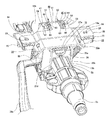
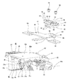
本発明の実施の形態の1例の通常時の状態を、支持ブラケットとエネルギ吸収部材とを組み合わせて後上方から見た状態で示す要部斜視図。The principal part perspective view which shows the state at the time of one example of embodiment of this invention in the state seen from the back upper direction combining the support bracket and the energy absorption member. 同じく、より幅方向中央に近い、後上方から見た状態で示す要部斜視図。Similarly, the principal part perspective view shown in the state seen from the back upper direction nearer to the center of the width direction. 同じく、エネルギ吸収部材とガイド部材とを組み合わせ、これらエネルギ吸収部材及びガイド部材を支持ブラケットと組み合わせる以前の状態を、側方に近い前上方から見た状態で示す要部斜視図。Similarly, the principal part perspective view which shows the state before combining an energy absorption member and a guide member, and combining these energy absorption members and a guide member with a support bracket in the state seen from the front upper direction near a side. 同じく、エネルギ吸収部材とガイド部材と支持ブラケットとを組み合わせる以前の状態を、より幅方向中央に近い、前上方から見た状態で示す要部斜視図。Similarly, the principal part perspective view which shows the state before combining an energy absorption member, a guide member, and a support bracket in the state seen from the front upper direction nearer to the center of the width direction. 同じく、より側方から見た状態で示す斜視図。Similarly, the perspective view shown in the state seen from the side. 同じく、側方に近い後上方から見た状態で示す要部斜視図。Similarly, the principal part perspective view shown in the state seen from the back upper direction near a side. 同じく、前下方から見た状態で示す斜視図。Similarly, the perspective view shown in the state seen from the front lower part. 全部品を組み立てて車体に対し支持した状態を、後上方から見た状態で示す斜視図。The perspective view which shows the state which assembled all the parts and supported with respect to the vehicle body in the state seen from back upper direction. 図8の中央部拡大図。The center part enlarged view of FIG. 二次衝突が進行した状態を、側方に近い前上方から見た状態で示す要部斜視図。The principal part perspective view which shows the state which the secondary collision advanced in the state seen from the front upper direction near a side. 本発明に関する参考例を、支持ブラケットとエネルギ吸収部材とを組み合わせて前上方から見た状態で示す要部斜視図。 The principal part perspective view which shows the reference example regarding this invention in the state seen from front upper direction combining the support bracket and the energy absorption member. 同じく、要部側面図。Similarly, the principal part side view. 同じく、要部平面図。Similarly, the principal part top view. 図13のA−A断面図。AA sectional drawing of FIG. 同B−B断面図。BB sectional drawing. 同じく、弾性係止部及びガイド鍔部を備えた取付用ブラケットを前上方から見た状態で示す斜視図。Similarly, the perspective view which shows the bracket for attachment provided with the elastic latching | locking part and the guide collar part in the state seen from the front upper direction. 同じく、車体側ブラケットを前上方から見た状態で示す斜視図。Similarly, the perspective view shown in the state which looked at the vehicle body side bracket from the front upper direction. 従来から知られているステアリング装置の1例を示す、部分切断側面図。The partial cut side view which shows an example of the steering apparatus known conventionally. 従前の衝撃吸収式ステアリング装置の1例を、前上方から見た状態で示す斜視図。The perspective view which shows one example of the conventional impact absorption type steering device in the state seen from front upper direction. 同じく断面図。Similarly sectional drawing. 同じく、車体側ブラケットを省略して示す、図19と同様の図。FIG. 20 is a view similar to FIG. 19, with the vehicle body side bracket omitted. 同じく、支持ブラケットを後下方から見た状態で示す斜視図。Similarly, the perspective view shown in the state which looked at the support bracket from back downward.

[実施の形態の1例]
図1〜10は、本発明の実施の形態の1例を示している。本例の衝撃吸収式ステアリング装置は、ステアリングコラム6bと、ステアリングシャフト5bと、被挟持部36と、コラム側通孔37と、支持ブラケット10aと、ブラケット側通孔である上下方向長孔26、26(図6、8、9及び前述の図22参照)と、調節杆27aと、この調節杆27aを含んで構成される調節手段38と、エネルギ吸収部材39と、ガイド部材40とを備える。そして、本例の構造の場合には、前記ステアリングシャフト5bの後端部に支持固定したステアリングホイール1(前述の図18参照)の高さ位置の調節を可能としている。更に、衝突事故に伴う二次衝突時に、前記ステアリングコラム6b及び前記ステアリングシャフト5bの全長を縮めると共に、前記エネルギ吸収部材39を塑性変形させつつ、前記ステアリングホイール1を前方に変位させる様にしている。
[ Example of Embodiment]
1 to 10 show an example of an embodiment of the present invention . The shock absorbing steering device of this example includes a steering column 6b, a steering shaft 5b, a sandwiched portion 36, a column side through hole 37, a support bracket 10a, and a vertically long hole 26 that is a bracket side through hole. 26 (see FIGS. 6, 8, 9 and FIG. 22 described above), an adjustment rod 27a, an adjustment means 38 including the adjustment rod 27a, an energy absorbing member 39, and a guide member 40. In the case of the structure of this example, the height position of the steering wheel 1 (see FIG. 18 described above) supported and fixed to the rear end portion of the steering shaft 5b can be adjusted. Further, in the event of a secondary collision due to a collision accident, the steering column 6b and the steering shaft 5b are shortened, and the energy absorbing member 39 is plastically deformed while the steering wheel 1 is displaced forward. .

前記ステアリングコラム6bは、前側に配置されたインナコラム14bの後部と、後側に配置されたアウタコラム13bの前部とを嵌合させている。このうちのインナコラム14bは、鉄系合金、或はアルミニウム系合金、マグネシウム系合金の如き軽合金等の、電縫管或は引き抜き管等で、全体を単なる円筒状に構成している。この様な前記インナコラム14aの前端部は、電動式パワーステアリング装置41を構成するハウジング16aの後端面に突設した保持筒部84に締り嵌めで内嵌すると共に、先端縁を、この保持筒部42の奥端面に形成した段差面に突き当てている。又、前記ハウジング16aは、前上端部に設置した支持管17に挿通した、特許請求の範囲に記載した横軸に相当する、ボルト等の枢軸部材により、車体に対して、上下方向に関する揺動変位のみを可能に支持している。従って、前記インナコラム14bは前記車体に、前後位置を規制された状態で支持されている。   The steering column 6b fits the rear part of the inner column 14b arranged on the front side and the front part of the outer column 13b arranged on the rear side. Of these, the inner column 14b is an electric sewing tube or a drawing tube, such as an iron alloy, a light alloy such as an aluminum alloy, or a magnesium alloy, and is entirely formed in a cylindrical shape. The front end portion of the inner column 14a is fitted into the holding cylinder portion 84 projecting from the rear end surface of the housing 16a constituting the electric power steering apparatus 41 with an interference fit, and the front end edge is set to the holding cylinder. It abuts on the step surface formed on the back end surface of the portion 42. The housing 16a swings in the vertical direction with respect to the vehicle body by a pivotal member such as a bolt, which corresponds to the horizontal axis described in the claims and is inserted through a support tube 17 installed at the front upper end. Supports only displacement. Therefore, the inner column 14b is supported by the vehicle body in a state where the front-rear position is restricted.

一方、前記アウタコラム13bは、アルミニウム系合金、マグネシウム系合金の如き軽合金をダイキャスト成形する等により一体に造られたもので、上面の中間部前寄り部分に、前記被挟持部36を形成している。又、前記アウタコラム13bの下端部のうちで後端部を除く部分にスリット42を、後端部を除き、このアウタコラム13bの前端縁に開口する状態で形成している。従って、このアウタコラム13bの前部で前記インナコラム14bの後部に外嵌している部分の直径は、弾性的に収縮可能である。又、前記アウタコラム13b前端部下面で、前記スリット42を幅方向両側から挟む部分に、1対のフランジ部43a、43bを設けている。そして、これら両フランジ部43a、43bに設けた通孔に挿通したボルト44の雄ねじ部と、ナット45に設けたねじ孔とを螺合し更に締め付ける事により、前記アウタコラム13bの前部の直径を弾性的に縮めて、このアウタコラム13bの前部内周面と前記インナコラム14bの後部外周面とを摩擦係合させている。尚、前記フランジ部43bの強度を十分に確保できれば、前記ボルト44の雄ねじ部を螺合させる為のねじ孔を、このフランジ部43bに直接形成する事もできる。何れにしても、前記ボルト44を締め付けるトルクを適切に規制する事により、前記アウタコラム13bの前部内周面と前記インナコラム14bの後部外周面との当接部の面圧を適正に調整できる。そして、これら両コラム13b、14bから成る、前記ステアリングコラム6bの全長を縮める為に要する荷重の大きさを調節できる。   On the other hand, the outer column 13b is integrally formed by die-casting a light alloy such as an aluminum alloy or a magnesium alloy, and the sandwiched portion 36 is formed in the front portion of the middle portion on the upper surface. doing. Further, a slit 42 is formed in a portion of the lower end portion of the outer column 13b excluding the rear end portion, and is formed in a state of opening to the front end edge of the outer column 13b excluding the rear end portion. Accordingly, the diameter of the portion of the front portion of the outer column 13b that is externally fitted to the rear portion of the inner column 14b can be elastically contracted. In addition, a pair of flange portions 43a and 43b are provided on the lower surface of the front end portion of the outer column 13b and sandwiching the slit 42 from both sides in the width direction. The diameter of the front portion of the outer column 13b is obtained by screwing and further tightening the male screw portion of the bolt 44 inserted into the through holes provided in both the flange portions 43a and 43b and the screw hole provided in the nut 45. Is elastically contracted, and the front inner peripheral surface of the outer column 13b and the rear outer peripheral surface of the inner column 14b are frictionally engaged. If the strength of the flange portion 43b can be sufficiently secured, a screw hole for screwing the male screw portion of the bolt 44 can be directly formed in the flange portion 43b. In any case, by properly regulating the torque for tightening the bolt 44, the surface pressure of the contact portion between the front inner peripheral surface of the outer column 13b and the rear outer peripheral surface of the inner column 14b can be adjusted appropriately. . And the magnitude | size of the load required in order to shorten the full length of the said steering column 6b which consists of these both columns 13b and 14b can be adjusted.

又、前記ステアリングシャフト5bは、例えば杆状のインナシャフトの端部と管状のアウタシャフトの端部とを非円形嵌合させて、トルクの伝達を可能にしている。又、これら両シャフトの端部同士の非円形嵌合部を、圧縮方向に大きな力が加わった場合に摺動可能として、前記ステアリングシャフト5bの全長を、二次衝突時に加わる衝撃エネルギにより、収縮可能としている。この様なステアリングシャフト5bは、前記ステアリングコラム6bの内径側に回転自在に支持した状態で、後端部をこのステアリングコラム6bの後端開口よりも後方に突出させている。そして、この突出させた部分に、前記ステアリングホイール1を支持固定可能としている。   Further, the steering shaft 5b is configured such that, for example, an end portion of a bowl-shaped inner shaft and an end portion of a tubular outer shaft are non-circularly fitted to enable transmission of torque. Further, the non-circular fitting portion between the end portions of both shafts is made slidable when a large force is applied in the compression direction, and the entire length of the steering shaft 5b is contracted by impact energy applied at the time of a secondary collision. It is possible. The steering shaft 5b has a rear end protruding rearward from the rear end opening of the steering column 6b in a state of being rotatably supported on the inner diameter side of the steering column 6b. The steering wheel 1 can be supported and fixed to the protruding portion.

又、前記被挟持部36は、前記アウタコラム13bの上面に設けている。本例の場合にこの被挟持部36は、このアウタコラム13bをダイキャスト成形するのと同時に形成したもので、互いに平行な左右1対の側板部同士の間に補強板部を設けた如き構造としている。これら両側板部の外側面(互いに反対側の側面)同士は互いに平行で、これら両外側面同士の間隔は、前記アウタコラム13bのうちで前記被挟持部36を設けた部分の外径(左右方向の幅寸法)と同じか、この外径よりも少しだけ大きくなっている。そして、前記コラム側通孔37は、前記被挟持部36(を構成する前記両側板部)の幅方向両端部の互いに整合する位置に(互いに同心に)、1対形成している。本例の場合、前記両コラム側通孔37は、前記調節杆27aの外径よりも僅かに大きな内径を有する、単なる円孔としている。   The sandwiched portion 36 is provided on the upper surface of the outer column 13b. In the case of this example, the sandwiched portion 36 is formed at the same time as the outer column 13b is die-cast, and has a structure in which a reinforcing plate portion is provided between a pair of left and right side plate portions parallel to each other. It is said. The outer side surfaces (side surfaces opposite to each other) of these both side plate portions are parallel to each other, and the interval between these outer side surfaces is the outer diameter (left and right) of the portion of the outer column 13b where the sandwiched portion 36 is provided. The width dimension in the direction) or slightly larger than this outer diameter. The column side through-holes 37 are formed in a pair (concentrically with each other) at positions that are aligned with each other at both ends in the width direction of the sandwiched portion 36 (the side plate portions constituting the sandwiched portion 36). In the case of this example, both the column side through holes 37 are simply circular holes having an inner diameter slightly larger than the outer diameter of the adjusting rod 27a.

又、前記支持ブラケット10aは、左右1対の挟持板部25c、25d、及び、これら両挟持板部25c、25dを車体に対して支持する取付板部18aを有する。そして、この取付板部18aを、二次衝突時に加わる衝撃荷重に基づいて前方への脱落を可能に、車体に対して支持する。前記両挟持板部25c、25d及び前記取付板部18aは、鋼板等の、十分な強度及び剛性を有する金属板に、プレス加工による打ち抜き加工及び曲げ加工を施して成る。前記支持ブラケット10aは、この様な前記両挟持板部25c、25d及び前記取付板部18aを、溶接等により接合固定して成る。又、このうちの両挟持板部25c、25dの互いに整合する部分に、前記両上下方向長孔26、26を形成している。これら両上下方向長孔26、26は、前記枢軸部材を中心とする、部分円弧状である。   The support bracket 10a has a pair of left and right sandwiching plate portions 25c and 25d, and a mounting plate portion 18a that supports the sandwiching plate portions 25c and 25d with respect to the vehicle body. And this mounting plate part 18a is supported with respect to a vehicle body so that it can drop | omit forward based on the impact load added at the time of a secondary collision. The sandwiching plate portions 25c and 25d and the mounting plate portion 18a are formed by stamping and bending a metal plate having sufficient strength and rigidity, such as a steel plate. The support bracket 10a is formed by joining and fixing the sandwiching plate portions 25c and 25d and the mounting plate portion 18a. In addition, both the vertically elongated holes 26 and 26 are formed in portions of the both clamping plate portions 25c and 25d that are aligned with each other. Both the vertical holes 26 and 26 have a partial arc shape centered on the pivot member.

又、これら両上下方向長孔26、26と、前記コラム側通孔37とに、前記調節杆27aを挿通している。この調節杆27aの基端部には、外向フランジ状の鍔部29(従前の構造を示す図20参照)を形成している。そして、この鍔部29の内側面に突設した凸部を、前記両挟持板部25c、25dのうちの一方の挟持板部25cに形成した上下方向長孔26に、この上下方向に沿った変位(昇降)のみ可能に(回転を阻止した状態で)係合させている。前記鍔部29が、特許請求の範囲に記載した1対の押圧部のうちの一方の押圧部に相当する。これに対して、他方の押圧部は、前記調節杆27aの中間部先端寄り部分に外嵌した被駆動側カム31(従前の構造を示す図20参照)が相当する。この被駆動側カム31は、前記両挟持板部25c、25dのうちの他方の挟持板部25dに形成した上下方向長孔に、昇降のみ可能に係合させている。   Further, the adjusting rod 27a is inserted through both the vertically elongated holes 26 and 26 and the column side through hole 37. An outward flange-like flange 29 (see FIG. 20 showing the conventional structure) is formed at the base end of the adjustment flange 27a. And the convex part which protruded on the inner surface of this collar part 29 was along this up-down direction long hole 26 formed in one clamping board part 25c of the said both clamping board parts 25c and 25d along this up-down direction. Engagement is possible only with displacement (lifting) (in a state where rotation is prevented). The flange portion 29 corresponds to one pressing portion of the pair of pressing portions described in the claims. On the other hand, the other pressing portion corresponds to the driven cam 31 (see FIG. 20 showing the conventional structure) that is fitted around the tip of the intermediate portion of the adjusting rod 27a. The driven cam 31 is engaged with an elongate hole formed in the other sandwiching plate portion 25d of the sandwiching plate portions 25c and 25d so as to be only movable up and down.

そして、前記調節杆27aの先端部に調節レバー33aを、この調節杆27aに対する相対回転を可能に、且つ、前記鍔部29から離れる方向への変位を阻止した状態で設置している。前記調節レバー33aの基端部内側面には駆動側カム30(従前の構造を示す図20参照)を、この調節レバー33aに対する相対回転を阻止した(この調節レバー33aと共に回転する)状態で設置している。そして、前記被駆動側カム31のカム面と前記駆動側カム30のカム面とを係合させてカム装置32(従前の構造を示す図20参照)を構成している。このカム装置32は、前記調節レバー33aの操作により軸方向寸法を拡縮する。この結果、前記1対の押圧部である、前記鍔部29と前記被駆動側カム31との間隔が拡縮される。   The adjustment lever 33a is installed at the tip of the adjustment rod 27a in a state that allows relative rotation with respect to the adjustment rod 27a and prevents displacement in a direction away from the flange 29. A drive cam 30 (see FIG. 20 showing the conventional structure) is installed on the inner side surface of the base end of the adjustment lever 33a in a state where relative rotation with respect to the adjustment lever 33a is prevented (rotates together with the adjustment lever 33a). ing. The cam surface of the driven cam 31 and the cam surface of the driving cam 30 are engaged to form a cam device 32 (see FIG. 20 showing the conventional structure). The cam device 32 expands or contracts the axial dimension by operating the adjustment lever 33a. As a result, the distance between the flange 29 and the driven cam 31 as the pair of pressing portions is expanded or reduced.

前記ステアリングホイール1の上下位置を調節する場合には、前記調節レバー33aを下方に揺動させて、前記カム装置32の軸方向寸法を縮め、前記被駆動側カム31と前記鍔部29との距離を拡げる。この状態で、前記調節杆27aが前記両上下方向長孔26内で変位できる範囲で、前記ステアリングコラム6bを、前記枢軸部材を中心として揺動変位させて、前記ステアリングホイール1の上下位置を調節する。本例の場合、前記ステアリングコラム6bと共に昇降する部分の重量は、前記アウタコラム13bと、前記支持ブラケット10aの取付板部18aとの間に設けた、引っ張りばねである釣合ばね35aにより支承して、前記ステアリングホイール1の上下位置の調節時に於ける、運転者の負担軽減を図っている。このステアリングホイール1の上下位置を調節したならば、前記調節レバー33aを上方に回動させて、前記被駆動側カム31と前記鍔部29との距離を縮め、前記両挟持板部25c、25dの内側面と前記被挟持部36の外側面とを摩擦係合させて、前記ステアリングホイール1の上下位置を固定する。   When adjusting the vertical position of the steering wheel 1, the adjusting lever 33 a is swung downward to reduce the axial dimension of the cam device 32, so that the driven cam 31 and the flange 29 Increase the distance. In this state, the vertical position of the steering wheel 1 is adjusted by swinging and displacing the steering column 6b around the pivot member within a range in which the adjustment rod 27a can be displaced in the vertical slots 26. To do. In this example, the weight of the portion that moves up and down together with the steering column 6b is supported by a balance spring 35a that is a tension spring provided between the outer column 13b and the mounting plate portion 18a of the support bracket 10a. Thus, the burden on the driver is reduced when the vertical position of the steering wheel 1 is adjusted. When the vertical position of the steering wheel 1 is adjusted, the adjustment lever 33a is rotated upward to shorten the distance between the driven cam 31 and the flange 29, and the both clamping plate portions 25c, 25d are adjusted. The upper and lower positions of the steering wheel 1 are fixed by frictionally engaging the inner surface of the steering wheel and the outer surface of the sandwiched portion 36.

更に、本例の場合には、次の(1) 〜(4) の構造を採用する事により、二次衝突時に前記ステアリングホイール1に衝突した運転者の身体に加わる衝撃を緩和する様にしている。
(1) 前記支持ブラケット10aを車体側ブラケット12a(図8、9参照)に対し、二次衝突時に加わる衝撃エネルギに基づいて、前方に脱落する様に支持している。
(2) 前記ステアリングコラム6bを、前記衝撃エネルギに基づいて全長を収縮可能に構成している。
(3) 前記ステアリングシャフト5bを、前記衝撃エネルギに基づいて全長を収縮可能に構成している。
(4) 前記支持ブラケット10aと前記車体側ブラケット12aとの間に、塑性変形しつつこの支持ブラケット10aの前方への変位を許容する、前記エネルギ吸収部材39を設けている。
これら(1) 〜(4) の構造のうち、(2)(3)の構造に関しては前述した通りであるから、重複する説明は省略する。又、(1) の構造に関しては、前述の図19〜21で説明した従前の構造と同様であるから、同等部分には同一符号を付して、説明を省略し、残りの(4) の構成に就いて、以下に説明する。
Further, in the case of this example, by adopting the following structures (1) to (4), the impact applied to the driver's body that collided with the steering wheel 1 during the secondary collision is alleviated. Yes.
(1) The support bracket 10a is supported on the vehicle body side bracket 12a (see FIGS. 8 and 9) so as to drop forward based on the impact energy applied during the secondary collision.
(2) The steering column 6b is configured such that its entire length can be contracted based on the impact energy.
(3) The steering shaft 5b is configured to be capable of contracting the entire length based on the impact energy.
(4) The energy absorbing member 39 is provided between the support bracket 10a and the vehicle body side bracket 12a to allow the support bracket 10a to be displaced forward while being plastically deformed.
Of these structures (1) to (4), the structures (2) and (3) are the same as described above, and a duplicate description is omitted. The structure (1) is the same as the previous structure described with reference to FIGS. 19 to 21 described above. Therefore, the same reference numerals are given to the equivalent parts, and the description thereof is omitted. The configuration will be described below.

前記車体側ブラケット12aと前記支持ブラケット10aとの間に、前記エネルギ吸収部材39を設けている。このうちの車体側ブラケット12aは、図8〜9に示す様に、左右の前フェンダ同士の間に掛け渡された状態で設けられて車体の一部を構成する補強パイプ46の中間部下面に溶接固定されている。前記エネルギ吸収部材39の基板部47は、前記支持ブラケット10aに係止したカプセル22、22と共に前記車体側ブラケット12aに、図示しないボルト若しくはスタッドにより結合される。そして、二次衝突時にも、この車体側ブラケット12aに結合されたまま、前方に離脱する事はない。これに対して、前記エネルギ吸収部材39の塑性変形部48は、前記支持ブラケット10aに支持されたガイド部材40に係止されていて、二次衝突時に、この支持ブラケット10aの前方への変位に伴って塑性変形する。   The energy absorbing member 39 is provided between the vehicle body side bracket 12a and the support bracket 10a. Of these, as shown in FIGS. 8 to 9, the vehicle body side bracket 12 a is provided in a state of being laid between the left and right front fenders, and is formed on the lower surface of the intermediate portion of the reinforcing pipe 46 constituting a part of the vehicle body. It is fixed by welding. The substrate portion 47 of the energy absorbing member 39 is coupled to the vehicle body side bracket 12a together with capsules 22 and 22 locked to the support bracket 10a by bolts or studs (not shown). Even in a secondary collision, the vehicle body side bracket 12a remains connected to the vehicle body side bracket 12a and does not move forward. On the other hand, the plastic deformation portion 48 of the energy absorbing member 39 is locked to the guide member 40 supported by the support bracket 10a, so that the support bracket 10a is displaced forward in a secondary collision. Accompanying plastic deformation.

より具体的に説明すると、前記エネルギ吸収部材39は、軟鋼板等の塑性変形可能な金属板製の素材に、プレスによる打ち抜き加工、曲げ加工を施す事により、一体に造っており、前記基板部47と前記塑性変形部48とを有する。このうちの基板部47は、幅方向に長い長矩形で、前記支持ブラケット10aを構成する取付板部18aの形状に合わせて、幅方向に関して両端部を中央部に対して下方にオフセットし、これら幅方向両端部と中央部とを、傾斜部により連続させている。前記塑性変形部48は、この様な基板部47の前端縁の幅方向中央部から前方に延出された帯状板部の中間部をU字形に折り返して成るもので、上側板部50と、折り返し部51と、下側板部52とを備える。このうちの上側板部50は、前記基板部47と同一平面上に、この基板部47から前方に連続する状態で設けられている。又、前記折り返し部51は、180度折り返された半円筒形で、前記上側板部50の前端縁に基端縁を連続させている。又、前記下側板部52は、前記折り返し部51の先端縁から後方に延出する状態で設けられている。前記塑性変形部48が塑性変形する以前の状態(二次衝突が発生していない、通常状態)では、前記下側板部52の先端部(後端部)は、前記基板部47の後端縁よりも後方に突出している。更に、本例の場合には、前記折り返し部51の両側縁部に円弧状の切り欠き部53、53を形成して、この折り返し部51の幅寸法を、前記上側、下側両板部50、52の幅寸法よりも小さくしている。 More specifically, the energy absorbing member 39 is integrally formed by subjecting a material made of a plastically deformable metal plate such as a mild steel plate to a punching process and a bending process using a press, and the substrate portion. 47 and the plastic deformation portion 48. Of these, the board portion 47 is a long rectangle that is long in the width direction, and in accordance with the shape of the mounting plate portion 18a constituting the support bracket 10a , both end portions are offset downward with respect to the center portion in the width direction. The width direction both ends and the central part are made continuous by the inclined part. The plastic deformation portion 48 is formed by folding an intermediate portion of a belt-like plate portion that extends forward from the center portion in the width direction of the front end edge of such a substrate portion 47 into an U-shape. A folded portion 51 and a lower plate portion 52 are provided. Of these, the upper plate portion 50 is provided on the same plane as the substrate portion 47 so as to be continuous forward from the substrate portion 47. The folded portion 51 has a semi-cylindrical shape folded by 180 degrees, and a base end edge is continued to the front end edge of the upper plate portion 50. The lower plate portion 52 is provided so as to extend rearward from the leading edge of the folded portion 51. In a state before the plastic deformation portion 48 is plastically deformed (secondary collision does not occur, normal state), the front end portion (rear end portion) of the lower plate portion 52 is the rear end edge of the substrate portion 47. Protrudes backwards. Further, in the case of this example, arc-shaped notches 53 and 53 are formed at both side edges of the folded portion 51, and the width dimension of the folded portion 51 is set to the upper and lower both plate portions 50. , 52 is smaller than the width dimension.

一方、前記ガイド部材40は、ポリアミド樹脂(ナイロン)、ポリ四フッ化エチレン樹脂(PTFE)、ポリアセタール樹脂等の滑り易い合成樹脂を射出成形する等により、一体に造ったもので、扱き板部54と、抑え板部55と、挿通部56とを備える。このうちの扱き板部54は、前端縁を半円筒面状の凸曲面とすると共に、上下両面を、前記エネルギ吸収部材39の塑性変形部48を構成する上側、下側両板部50、52を摺接させるガイド面としている。又、前記抑え板部55は、前記扱き板部54の下側に設けられている。図示の例では、これら抑え板部55の上面と扱き板部54の下面との間に中間板を設けると共に、これら抑え板55と中間板との左右両側縁同士を側板で接続して、当該部分を矩形筒状に形成している。この様な構造は、前記抑え板部55の強度及び剛性を確保する面から有利であるが、この抑え板部55の強度及び剛性を確保できるのであれば、前記中間板及び両側板は、省略しても良い。   On the other hand, the guide member 40 is integrally formed by injection molding of slippery synthetic resin such as polyamide resin (nylon), polytetrafluoroethylene resin (PTFE), polyacetal resin or the like. And a holding plate portion 55 and an insertion portion 56. Among these, the handling plate portion 54 has a front end edge formed as a semi-cylindrical convex curved surface, and upper and lower both plate portions 50 and 52 constituting the plastic deformation portion 48 of the energy absorbing member 39 on both upper and lower surfaces. It is used as a guide surface for sliding contact. Further, the holding plate portion 55 is provided below the handling plate portion 54. In the example shown in the drawing, an intermediate plate is provided between the upper surface of the holding plate portion 55 and the lower surface of the handling plate portion 54, and both left and right side edges of the holding plate 55 and the intermediate plate are connected by side plates. The part is formed in the rectangular cylinder shape. Such a structure is advantageous in terms of securing the strength and rigidity of the holding plate portion 55, but the intermediate plate and both side plates are omitted if the strength and rigidity of the holding plate portion 55 can be secured. You may do it.

又、前記挿通部56は、前記扱き板部54の下面と前記抑え板部55の上面との間に設けられたもので、前記下側板部52を挿通自在なスリット状である。又、前記扱き板部54の左右両側にガイド板部57、57を、この扱き板部54の上方乃至前方に突出する状態で形成している。これら両ガイド板部57、57の内側面同士の間隔は、前記エネルギ吸収部材39の塑性変形部48の幅寸法よりも僅かに大きくして、前記扱き板部54がこの塑性変形部48を扱く際に、この塑性変形部48が左右にぶれない様にしている。   The insertion portion 56 is provided between the lower surface of the handling plate portion 54 and the upper surface of the holding plate portion 55, and has a slit shape through which the lower plate portion 52 can be inserted. In addition, guide plate portions 57 and 57 are formed on the left and right sides of the handling plate portion 54 so as to protrude upward or forward from the handling plate portion 54. The distance between the inner surfaces of the guide plate portions 57 and 57 is slightly larger than the width dimension of the plastic deformation portion 48 of the energy absorbing member 39, and the handling plate portion 54 handles the plastic deformation portion 48. In this case, the plastic deformation portion 48 is prevented from moving left and right.

更に、本例の場合には、前記ガイド部材40に、前記各部54〜57に加えて、それぞれ1対ずつの弾性係止片58、58及びガイド鍔部59、59を、これら各部54〜57と共に、一体に設けている。このうちの両弾性係止片58、58は、前記扱き板部54の後端部両側方から上方に突出する状態で設けられており、それぞれの上端部外側面に、前後方向から見た形状が略三角形状である、鉤部60、60を設けている。これら両鉤部60、60の外側面は、上方に向うほど互いに近づく方向に傾斜している。一方、前記両ガイド鍔部59、59は、前記ガイド部材40を前記支持ブラケット10aの取付板部18aにねじ止め固定する為、前記扱き板部54の前半部から左右両側方に突出する状態で設けられた取付フランジ部61、61の先端面の上端部から、更に左右両側方に突出する状態で設けられている。   Further, in the case of this example, in addition to the respective portions 54 to 57, the guide member 40 is provided with a pair of elastic locking pieces 58 and 58 and guide flange portions 59 and 59, respectively. In addition, it is provided integrally. Of these, both elastic locking pieces 58, 58 are provided so as to protrude upward from both sides of the rear end portion of the handling plate portion 54, and are formed on the outer surface of each upper end portion as viewed from the front-rear direction. Are provided with the flange portions 60, 60 having a substantially triangular shape. The outer side surfaces of the both flange portions 60, 60 are inclined in a direction approaching each other as they go upward. On the other hand, the both guide flanges 59, 59 project from the front half of the handling plate 54 to the left and right sides in order to fix the guide member 40 to the mounting plate 18a of the support bracket 10a with screws. The mounting flanges 61 and 61 are provided so as to protrude further from the upper end of the front end surface to the left and right sides.

上述の様なガイド部材40を装着する為、前記取付板部18aの前端部に、前記ガイド部材40のうちの抑え板部55(及び中間板並びに両側板)を挿通可能な透孔62を形成している。前記ガイド部材40を前記取付板部18aに装着するには、前記抑え板部55を前記透孔62に前方から挿入し、前記扱き板部54の下面を前記取付板部18aの上面に当接させる。そして、前記両取付フランジ部61、61の取付孔を上方から挿通した取付ねじ63、63を、前記取付板部18aに設けたねじ孔に螺合し、更に締め付ける。一方、前記エネルギ吸収部材39は、前記塑性変形部48のうちの下側板部52を前記ガイド部材40の挿通部56に、前方から挿通し、前記折り返し部51の内周面を、前記扱き板部54の前端縁に、当接乃至は近接対向させる。前記ガイド部材40を前記取付板部18aに結合固定する作業と、このガイド部材40と前記エネルギ吸収部材39とを組み合わせる作業との前後は問わない。   In order to mount the guide member 40 as described above, a through hole 62 through which the holding plate portion 55 (and the intermediate plate and both side plates) of the guide member 40 can be inserted is formed at the front end portion of the mounting plate portion 18a. doing. In order to mount the guide member 40 on the mounting plate portion 18a, the holding plate portion 55 is inserted into the through hole 62 from the front, and the lower surface of the handling plate portion 54 is in contact with the upper surface of the mounting plate portion 18a. Let Then, the mounting screws 63, 63 inserted through the mounting holes of the mounting flange portions 61, 61 from above are screwed into the screw holes provided in the mounting plate portion 18a, and further tightened. On the other hand, the energy absorbing member 39 inserts the lower plate portion 52 of the plastic deformation portion 48 into the insertion portion 56 of the guide member 40 from the front, and the inner peripheral surface of the folded portion 51 is used as the handling plate. The front end of the portion 54 is brought into contact with or close to the front end edge. It does not matter before and after the operation of coupling and fixing the guide member 40 to the mounting plate portion 18a and the operation of combining the guide member 40 and the energy absorbing member 39.

何れにしても、前記ガイド部材40を前記取付板部18aに結合固定すると共に、このガイド部材40と前記エネルギ吸収部材39とを組み合わせたならば、このエネルギ吸収部材39を、前記支持ブラケット10aと共に、前記車体側ブラケット12aに支持する。この作業は、この支持ブラケット10aに装着した前記両カプセル22、22に形成した通孔23、23及び前記エネルギ吸収部材39の基板部47の両端部に形成した通孔64、64に挿通したボルト又はスタッドと、ナットとを螺合し更に締め付ける事により行う。このうちのスタッド又はナットは、前記車体側ブラケット12aに固定されているので、前記締め付け作業により、前記基板部47及び前記両カプセル22、22が、前記車体側ブラケット12aに対し、不離に結合支持される。又、前記支持ブラケット10aに関しても、前記両カプセル22、22を介して前記車体側ブラケット12aに、二次衝突時に前方への離脱可能に支持される。 In any case, when the guide member 40 is coupled and fixed to the mounting plate portion 18a, and the guide member 40 and the energy absorbing member 39 are combined, the energy absorbing member 39 is combined with the support bracket 10a. And supported by the vehicle body side bracket 12a. This operation is performed by bolts inserted through the through holes 23, 23 formed in the capsules 22, 22 attached to the support bracket 10a and through holes 64, 64 formed at both ends of the substrate portion 47 of the energy absorbing member 39. Alternatively, it is performed by screwing the stud and the nut and further tightening. Of these, the stud or nut is fixed to the vehicle body side bracket 12a, so that the base plate portion 47 and the capsules 22 and 22 are coupled and supported to the vehicle body side bracket 12a by the tightening operation. Is done. Further, the support bracket 10a is also supported by the vehicle body side bracket 12a via the capsules 22 and 22 so as to be able to be detached forward in a secondary collision.

上述の様に、前記ボルト又はスタッドとナットとを螺合し更に締め付ける際に、そのままでは前記支持ブラケット10aと組み合わされた、前記ステアリングコラム6bや前記ステアリングシャフト5b等の重量を支えつつ作業を行う必要がある。この様な作業は、作業員の負担が大きいので、本例の場合には、前記両弾性係止片58、58を利用して、前記作業に関する負担の軽減を図っている。この為に本例の場合には、前記車体側ブラケット12aの一部に、それぞれが前後方向に長い1対の係止透孔65、65(図8、9参照)を、互いに平行に形成している。又、これら両係止透孔65、65の中間部後端寄り部分の互いに反対側の側縁部を矩形状に切り欠いて、当該部分を幅広孔部66、66としている。   As described above, when the bolt or stud and nut are screwed together and further tightened, the work is performed while supporting the weight of the steering column 6b, the steering shaft 5b, etc., which is combined with the support bracket 10a as it is. There is a need. Since such an operation is a heavy burden on the worker, in the case of this example, the both elastic locking pieces 58 and 58 are used to reduce the burden on the operation. For this reason, in the case of this example, a pair of locking through holes 65 and 65 (see FIGS. 8 and 9), each of which is long in the front-rear direction, are formed in a part of the vehicle body side bracket 12a in parallel with each other. ing. Further, the side edge portions on the opposite sides of the portions near the rear end of the intermediate portion of both the locking through holes 65, 65 are cut out in a rectangular shape, and the portions are formed as wide hole portions 66, 66.

本例の衝撃吸収式ステアリング装置を組み立てる場合には、先ず、前記ステアリングコラム6b及び前記ステアリングシャフト5b等と前記支持ブラケット10aとを組み合わせる。次いで、前記支持管17にボルト等の枢軸部材を挿通する事により、前記ハウジング16aを車体に対して、上下方向に関する揺動変位を可能に支持する。その後、前記ステアリングコラム6bを前記枢軸部材を中心に上方に揺動(前記支持ブラケット10aを上昇)させる。車体の前後左右方向に関する位相(各部の寸法及び形状)は、予め適正に規制している。従って、前記支持ブラケット10aが上昇すると、前記両弾性係止片58、58の鉤部60、60の上面が、前記両係止透孔65、65の後端部反対側縁と係合する(擦れ合う)。   When assembling the shock absorbing type steering apparatus of this example, first, the steering column 6b, the steering shaft 5b and the like are combined with the support bracket 10a. Next, by inserting a pivot member such as a bolt into the support tube 17, the housing 16a is supported with respect to the vehicle body so as to be swingable in the vertical direction. Thereafter, the steering column 6b is swung upward (the support bracket 10a is raised) about the pivot member. The phase (size and shape of each part) in the front-rear and left-right directions of the vehicle body is appropriately regulated in advance. Therefore, when the support bracket 10a is raised, the upper surfaces of the flange portions 60, 60 of the both elastic locking pieces 58, 58 engage with the opposite edges of the rear end portions of the both locking through holes 65, 65 ( rub against).

この状態から更に前記支持ブラケット10aを上昇させると、前記両弾性係止片58、58が弾性変形しつつ、前記両鉤部60、60が前記両係止透孔65、65の内側を通過し、通過後に、前記両弾性係止片58、58が弾性的に復元する。この際、前記両ガイド鍔部59、59は、前記両幅広孔部66、66を通過して前記車体側ブラケット12aの上方に突出する。上述の様に、前記両弾性係止片58、58が弾性的に復元した状態では、前記両鉤部60、60の下端面と、前記車体側ブラケット12aのうちで、前記両係止透孔65、65の後端部反対側縁部の上面とが係合して、前記支持ブラケット10a等の重量が前記両鉤部60、60により支承される。この結果、前記重量を支えつつ、前記ボルト又はスタッドとナットとを螺合し更に締め付ける作業を行う必要がなくなり、作業員に掛ける負担の軽減を図れる。   When the support bracket 10a is further raised from this state, both the elastic locking pieces 58, 58 are elastically deformed, and the both flange portions 60, 60 pass inside the both locking through holes 65, 65. After passing, both the elastic locking pieces 58, 58 are elastically restored. At this time, the both guide flanges 59, 59 protrude above the vehicle body side bracket 12a through the both wide hole portions 66, 66. As described above, when both the elastic locking pieces 58 and 58 are elastically restored, the both locking through holes are formed between the lower end surfaces of the both flange portions 60 and 60 and the vehicle body side bracket 12a. The upper surfaces of the opposite edge portions of the rear end portions 65 and 65 are engaged with each other, and the weight of the support bracket 10a and the like is supported by the both flange portions 60 and 60. As a result, it is not necessary to perform the work of screwing the bolts or studs and nuts and tightening them while supporting the weight, and the burden on the worker can be reduced.

上述の様にして前記支持ブラケット10aを前記車体側ブラケット12aに支持すると、前記エネルギ吸収部材39は、図1、2に示す様に前記支持ブラケット10aと組み合わされた状態で、その基板部47を前記車体側ブラケット12aに結合される。
衝突事故に伴う二次衝突が発生すると、前述の図19〜22に示した従前の構造と同様、図10に示す様に、前記両カプセル22、22を前記支持ブラケット10aの切り欠き21、21から抜き出しつつ、この支持ブラケット10aが前方に変位する。前記アウタコラム13bは、前記調節杆27aにより、この支持ブラケット10aに対し結合されている。従って、二次衝突時には、前記アウタコラム13bも、前方に変位する。これに対して、前記インナコラム14bは、前方に変位する事はないので、これらアウタコラム13bの前部内周面と前記インナコラム14bの後部外周面との嵌合部が滑り(摩擦係合し)、前記ステアリングコラム6bの全長は縮まる。
When the support bracket 10a is supported on the vehicle body side bracket 12a as described above, the energy absorbing member 39 is attached to the support bracket 10a as shown in FIGS. The vehicle body side bracket 12a is coupled.
When a secondary collision occurs due to a collision accident, as shown in FIG. 10, both capsules 22 and 22 are notched 21 and 21 in the support bracket 10a as in the conventional structure shown in FIGS. The support bracket 10a is displaced forward while being pulled out from the front. The outer column 13b is coupled to the support bracket 10a by the adjusting rod 27a. Therefore, at the time of a secondary collision, the outer column 13b is also displaced forward. On the other hand, since the inner column 14b is not displaced forward, the fitting portion between the front inner peripheral surface of the outer column 13b and the rear outer peripheral surface of the inner column 14b is slipped (frictionally engaged). ), The entire length of the steering column 6b is reduced.

又、前記アウタコラム13bと共に前記支持ブラケット10aが前方に変位するのに伴って、前記エネルギ吸収部材39の塑性変形部48が、例えば図3に示した通常状態から、図10に示した状態にまで伸長する。即ち、前記支持ブラケット10aが前方に変位すると、この支持ブラケット10aに固定した、前記ガイド部材40の扱き板部54が、前記塑性変形部48の折り返し部51の内周面を前方に押圧する。すると、この折り返し部51が前記扱き板部54の前端縁により扱かれつつ、前記塑性変形部48を構成する、前記下側板部52の先端部に向けて移動する。前述した様に、通常時に於ける前記折り返し部51の幅寸法は小さい。この為、この移動開始の瞬間に要するエネルギは小さくて済み、前記塑性変形部48の塑性変形を開始する瞬間に運転者の身体に加わる衝撃を小さく抑えられる。又、前記折り返し部51が前記下側板部52の先端部に向けて移動する際、この下側板部52は下方に変位する傾向になるが、この変位は、前記抑え板部55により阻止される為、前記上側、下側両板部50、52同士の位置関係は、ほぼ平行のままに維持され、前記折り返し部51の移動は、安定して行われる。 Further, as the support bracket 10a is displaced forward together with the outer column 13b, the plastic deformation portion 48 of the energy absorbing member 39 changes from the normal state shown in FIG. 3, for example, to the state shown in FIG. Extend to. That is, when the support bracket 10a is displaced forward, the handling plate portion 54 of the guide member 40 fixed to the support bracket 10a presses the inner peripheral surface of the folded portion 51 of the plastic deformation portion 48 forward. Then, the folded portion 51 moves toward the tip end portion of the lower plate portion 52 constituting the plastic deformation portion 48 while being handled by the front end edge of the handling plate portion 54. As described above, the width dimension of the folded portion 51 in the normal time is small. For this reason, the energy required at the moment of starting the movement is small, and the impact applied to the driver's body at the moment of starting the plastic deformation of the plastic deformation portion 48 can be suppressed small. Further, when the folded portion 51 moves toward the tip end portion of the lower plate portion 52, the lower plate portion 52 tends to be displaced downward, but this displacement is blocked by the holding plate portion 55. Therefore, the positional relationship between the upper and lower plate portions 50 and 52 is maintained substantially parallel, and the folding portion 51 is moved stably.

以上に述べた様に、本例の衝撃吸収式ステアリング装置の場合には、二次衝突時の衝撃エネルギを、前記アウタコラム13bの前部内周面と前記インナコラム14bの後部外周面との嵌合部の摩擦抵抗と、前記エネルギ吸収部材39の塑性変形部48の塑性変形とにより吸収する。この塑性変形部48の塑性変形は、上述した様に安定して行われる為、前記衝撃エネルギを安定して吸収できる。又、この際に衝撃エネルギを吸収する特性は、前記エネルギ吸収部材39を構成する金属板の厚さや材質、前記塑性変形部48の形状や寸法を変える事により、任意に調節できる。この為、運転者の保護を充実させる為の設計の自由度が高い。   As described above, in the case of the shock absorbing steering device of this example, the impact energy at the time of the secondary collision is applied between the front inner peripheral surface of the outer column 13b and the rear outer peripheral surface of the inner column 14b. It absorbs by the frictional resistance of the joint part and the plastic deformation of the plastic deformation part 48 of the energy absorbing member 39. Since the plastic deformation of the plastic deformation portion 48 is performed stably as described above, the impact energy can be stably absorbed. Further, the characteristic of absorbing impact energy at this time can be arbitrarily adjusted by changing the thickness and material of the metal plate constituting the energy absorbing member 39 and the shape and size of the plastic deformation portion 48. For this reason, there is a high degree of design freedom to enhance driver protection.

更に、本例の衝撃吸収式ステアリング装置の場合には、二次衝突に基づいて前記アウタコラム13bと共に前記支持ブラケット10aが前方に変位する過程で、前記両カプセル22、22が前記切り欠き21、21から抜け出る以前に、前記両ガイド鍔部59、59が、前記両透孔62、62のうちの幅広孔部66、66よりも前方に変位する。そして、前記両カプセル22、22が前記切り欠き21、21から抜け出しきった状態でも、前記両ガイド鍔部59、59と、前記車体側ブラケット12aのうちで、前記両係止透孔65、65の中間部乃至前端部の反対側縁部の上面との係合に基づいて、前記支持ブラケット10aが落下する事を防止する。この為、二次衝突が進行した状態でも、前記ステアリングホイール1の後側で膨らんだエアバッグと運転者の身体との位置関係を適正のままに維持できて、運転者の保護をより一層充実させられる。又、軽度の衝突事故の際には、前記ステアリングホイール1の操作を可能にして、事故車両の撤去作業を容易に行える。 Further, in the case of the shock absorbing type steering apparatus of the present example, both the capsules 22 and 22 are moved to the notches 21 and 22 while the support bracket 10a is displaced forward together with the outer column 13b based on the secondary collision. Before exiting from the guide 21, the two guide flanges 59, 59 are displaced more forward than the wide holes 66, 66 of the two through holes 62, 62. Even when the capsules 22 and 22 are completely pulled out of the notches 21 and 21, the locking through holes 65 and 65 of the guide flanges 59 and 59 and the vehicle body side bracket 12a are used. The support bracket 10a is prevented from falling on the basis of the engagement with the upper surface of the opposite edge portion of the intermediate portion or the front end portion. For this reason, even when a secondary collision progresses, the positional relationship between the airbag inflated on the rear side of the steering wheel 1 and the driver's body can be maintained as appropriate, thereby further enhancing the protection of the driver. Be made. In the case of a minor collision accident, the steering wheel 1 can be operated to easily remove the accident vehicle.

尚、本例の場合には、前記エネルギ吸収部材39の平面形状をT字形としている為、前述の特許文献6に記載された様な、平面形状がY字形のエネルギ吸収部材に比べて、設置の自由度が高い。即ち、電動式パワーステアリング装置の構成部品や、前記両弾性係止片58、58及び前記両ガイド鍔部59、59との干渉を防止しつつ、所望のエネルギ吸収性能を有する、前記エネルギ吸収部材39の設置が可能となり、衝撃吸収式ステアリング装置の設計の自由度を高くできる。   In the case of this example, since the planar shape of the energy absorbing member 39 is T-shaped, the planar shape is installed as compared with the energy absorbing member whose Y-shaped planar shape is described in Patent Document 6 described above. High degree of freedom. That is, the energy absorbing member having a desired energy absorbing performance while preventing interference with the components of the electric power steering device, the elastic locking pieces 58 and 58, and the guide flanges 59 and 59. 39 can be installed, and the degree of freedom in designing the shock absorbing steering system can be increased.

[本発明に関する参考例]
図11〜17は、本発明に関する参考例を示している。本参考例の構造の場合には、ステアリングホイール1(図18参照)の上下位置を調節する為のチルト機構に加えて、前後位置を調節する為のテレスコピック機構を組み込んでいる。この為に本参考例の構造の場合には、インナコラム14cと、アウタコラム13cと、ステアリングシャフト5bと、特許請求の範囲に記載した被挟持部を構成する1対の被挟持壁部11a、11aと、それぞれがコラム側通孔である、1対の前後方向長孔28、28と、支持ブラケット10bと、1対の上下方向長孔26a、26bと、調節杆27aと、この調節杆27aと共に調節手段38を構成する調節手段であるカム装置32と、エネルギ吸収部材39aとを備える。
[ Reference Example for the Present Invention ]
11-17 has shown the reference example regarding this invention . In the case of the structure of this reference example , in addition to the tilt mechanism for adjusting the vertical position of the steering wheel 1 (see FIG. 18), a telescopic mechanism for adjusting the front-rear position is incorporated. Therefore, in the case of the structure of the present reference example , the inner column 14c, the outer column 13c, the steering shaft 5b, and a pair of sandwiched wall portions 11a constituting the sandwiched portion described in the claims, 11a, a pair of longitudinal elongated holes 28, 28, each of which is a column side through hole, a support bracket 10b, a pair of vertically elongated holes 26a, 26b, an adjustment rod 27a, and this adjustment rod 27a In addition, a cam device 32 which is an adjusting means constituting the adjusting means 38 and an energy absorbing member 39a are provided.

このうちのインナコラム14cは、上述した実施の形態の1例の場合と同様の構造により、二次衝突時にも前方に変位しない様にした状態で、前記アウタコラム13cよりも前側に配置している。又、前記インナコラム14cは、全体が円管状で、外周面のうちで前端部を除く部分に、それぞれが軸方向に長い複数本(偶数本、図示の例では6本)の突条67、67を、円周方向に関して等間隔に形成している。又、前記アウタコラム13cは、例えばアルミニウム合金のダイキャスト成形により一体に造られている。そして、このアウタコラム13cの前部を前記インナコラム14cの後部に外嵌して、伸縮可能なステアリングコラム6cを構成している。本参考例の場合には、これらアウタコラム13cの内周面とインナコラム14cの外周面とを、前記各突条67、67の頂部で当接させて、これら両周面同士の嵌合部の摩擦状態を安定させている。又、これら両周面同士の摩擦係合に基づき、前記インナコラム14cに対する前記アウタコラム13cの前後位置の調節及び固定を可能としている。この為に、このアウタコラム13cのうち、前記インナコラム14cとの嵌合部である前部にスリット42a(図15参照)を、軸方向に設けて、この前部の直径を弾性的に拡縮可能としている。前記アウタコラム13cは、この様に直径を拡縮可能とした前部を前記インナコラム14cの後部に外嵌し、このインナコラム14cに対する軸方向の変位に基づいて、前後位置の調節を可能としている。 Of these, the inner column 14c is arranged in front of the outer column 13c in a state in which the inner column 14c is not displaced forward even during a secondary collision by the same structure as in the example of the embodiment described above. Yes. Further, the inner column 14c has a tubular shape as a whole, and a plurality of protrusions 67 (even numbers, six in the illustrated example), each of which is long in the axial direction, are formed on the outer peripheral surface excluding the front end portion. 67 are formed at equal intervals in the circumferential direction. The outer column 13c is integrally formed by die casting of an aluminum alloy, for example. The front column of the outer column 13c is externally fitted to the rear portion of the inner column 14c to constitute a telescopic steering column 6c. In the case of this reference example , the inner peripheral surface of the outer column 13c and the outer peripheral surface of the inner column 14c are brought into contact with the tops of the protrusions 67 and 67, and a fitting portion between these two peripheral surfaces is provided. This stabilizes the friction state. Further, based on the frictional engagement between the two peripheral surfaces, the front / rear position of the outer column 13c relative to the inner column 14c can be adjusted and fixed. For this purpose, a slit 42a (see FIG. 15) is provided in the front portion of the outer column 13c, which is a fitting portion with the inner column 14c, so that the diameter of the front portion is elastically expanded / contracted. It is possible. In the outer column 13c, the front part whose diameter can be expanded and contracted is externally fitted to the rear part of the inner column 14c, and the front / rear position can be adjusted based on the axial displacement with respect to the inner column 14c. .

又、前記ステアリングシャフト5bは、後半部を構成するアウタシャフト68の前半部内周面に形成した雌スプライン歯と、前半部を構成するインナシャフト69の後半部外周面に形成した雄スプライン歯とをスプライン係合させる事により、全長を伸縮可能に組み合わせて成る。そして、前記雄スプライン歯と前記雌スプライン歯とのうちの少なくとも一方の歯の表面に、ポリアミド樹脂、ポリ四フッ化エチレン樹脂、ポリアセタール樹脂等の、摩擦係数が低い合成樹脂製のコーティング層を形成している。従って、前記アウタシャフト68と前記インナシャフト69とは、トルクの伝達を可能に、且つ、軽い力で伸縮可能に組み合わされている。この様な、前記ステアリングシャフト5bは、前記ステアリングコラム6cの内径側に回転自在に支持されている。具体的には、前記アウタシャフト68の中間部後端寄り部分を、前記アウタコラム13cの後端部の内径側に、単列深溝型玉軸受の如く、ラジアル荷重及びアキシアル荷重を支承可能な転がり軸受により、回転のみ自在に支持している。従って前記アウタシャフト68は、前記アウタコラム13cの軸方向移動に伴って移動し、前記ステアリングシャフト5bが伸縮する。   The steering shaft 5b includes female spline teeth formed on the inner peripheral surface of the front half of the outer shaft 68 constituting the rear half, and male spline teeth formed on the outer peripheral surface of the rear half of the inner shaft 69 constituting the front half. By spline engagement, the entire length can be expanded and contracted. A synthetic resin coating layer having a low friction coefficient, such as polyamide resin, polytetrafluoroethylene resin, or polyacetal resin, is formed on the surface of at least one of the male spline teeth and the female spline teeth. doing. Therefore, the outer shaft 68 and the inner shaft 69 are combined so as to be able to transmit torque and extend and contract with a light force. Such a steering shaft 5b is rotatably supported on the inner diameter side of the steering column 6c. More specifically, the intermediate shaft rear end portion of the outer shaft 68 is provided on the inner diameter side of the rear end portion of the outer column 13c so that a radial load and an axial load can be supported like a single row deep groove ball bearing. Only the rotation is supported by the bearing. Accordingly, the outer shaft 68 moves as the outer column 13c moves in the axial direction, and the steering shaft 5b expands and contracts.

又、前記両被挟持壁部11a、11aは、前記アウタコラム13cの前部の下面で前記スリット42aを左右両側から挟む位置に、このアウタコラム13cと一体に設けられている。そして、前記両被挟持壁部11a、11aの互いに整合する位置に、前記両前後方向長孔28、28を、それぞれ前記アウタコラム13cの軸方向に形成している。   Further, the both sandwiched wall portions 11a and 11a are integrally provided with the outer column 13c at a position where the slit 42a is sandwiched from the left and right sides on the lower surface of the front portion of the outer column 13c. The front and rear direction long holes 28 and 28 are formed in the axial direction of the outer column 13c at positions where the both sandwiched wall portions 11a and 11a are aligned with each other.

又、前記支持ブラケット10bは、前述した実施の形態の1例を構成する支持ブラケット10aと同様に、左右1対の挟持板部25e、25f及び取付板部18bを有する。このうちの前記両挟持板部25e、25fは、前記アウタコラム13cの下面に設けた前記両被挟持壁部11a、11aを、左右両側から挟持する。又、前記取付板部18bは、前述の図19〜22に示した従前構造及び図1〜10に示した実施の形態の1例の場合と同様の構造で車体に対し支持して、二次衝突時に前記アウタコラム13cが前方に変位する事を許容する。又、前記両挟持板部25e、25fの互いに整合する位置に、前記従前構造及び実施の形態の1例の構造の場合と同様に、前記ステアリングコラム6cの揺動中心をその中心とする、部分円弧状の上下方向長孔26a、26bを形成している。 The support bracket 10b has a pair of left and right clamping plate portions 25e and 25f and a mounting plate portion 18b, similar to the support bracket 10a constituting an example of the embodiment described above. Of these, the sandwiching plate portions 25e and 25f sandwich the sandwiched wall portions 11a and 11a provided on the lower surface of the outer column 13c from both the left and right sides. The mounting plate portion 18b is supported on the vehicle body with the same structure as the conventional structure shown in FIGS. 19 to 22 and the example of the embodiment shown in FIGS. The outer column 13c is allowed to be displaced forward during a collision. Further, in the same manner as in the case of the conventional structure and the structure of one example of the embodiment, a part having the swing center of the steering column 6c as the center is located at a position where the both clamping plate portions 25e and 25f are aligned with each other. Arc-shaped vertical holes 26a and 26b are formed.

そして、前記調節杆27aを、前記両上下方向長孔26a、26bと前記両前後方向長孔28、28とに挿通している。前記調節杆27aは、中間部先端寄り部分(図15の右寄り部分)に、この調節杆27aの中央寄りから順番に、摩擦プレート70aと、チルトスペーサ71と、ワッシャ72と、スラスト軸受73とを外嵌している。そして、前記調節杆27aの先端部に螺着したナット74により、これら各部材70a〜73がこの調節杆27aから抜け出る事を防止している。又、前記ナット74は、必要箇所に螺着後、何れかの部分をかしめ変形する事により、緩み止めを図っている。尚、前記各部材70a〜73のうち、チルトスペーサ71と、ワッシャ72と、スラスト軸受73とは、前記ステアリングホイールの位置調節の際に、前記調節杆27aの変位、並びに、前記調節杆27aの先端部の前記上下方向長孔26aに沿う変位が、それぞれ円滑に行われる様に設けている。これに対して、前記摩擦プレート70aは、前述の特許文献7に記載された発明の構造と同様に、前記アウタコラム13c側に設けた別の摩擦プレート70bとの共働で、前記ステアリングホイール1を、調節後の位置に保持する為の保持力を大きくする為に設けている。これらの部分の構造及び作用に就いては、従来から知られており、本発明の要旨とも関係しないので、詳しい説明は省略する。 Then, the adjustment rod 27a, the two vertically long holes 26a, are inserted 26b and the on the both front-back direction long holes 28, 28. The adjusting rod 27a has a friction plate 70a, a tilt spacer 71, a washer 72, and a thrust bearing 73 in order from the center of the adjusting rod 27a in the middle of the middle portion (the right-side portion in FIG. 15). It is fitted. The members 70a to 73 are prevented from coming out of the adjusting rod 27a by a nut 74 screwed to the tip of the adjusting rod 27a. Further, after the nut 74 is screwed to a necessary portion, any portion is caulked and deformed to prevent loosening. Of the members 70a to 73, the tilt spacer 71, the washer 72, and the thrust bearing 73 are used to adjust the displacement of the adjustment rod 27a and the adjustment rod 27a when adjusting the position of the steering wheel. Displacement along the up-and-down direction long hole 26a of a front-end | tip part is provided so that each may be performed smoothly. On the other hand, like the structure of the invention described in Patent Document 7 described above, the friction plate 70a cooperates with another friction plate 70b provided on the outer column 13c side, and thus the steering wheel 1 Is provided in order to increase the holding force for holding in the adjusted position. Since the structure and operation of these parts are conventionally known and are not related to the gist of the present invention, detailed description thereof is omitted.

一方、前記調節杆27aの基端部に、前述の図19〜22に示した従前の構造及び実施の形態の1例と同様に、駆動側カム30と被駆動側カム31とから成る、前記カム装置32を設けている。本参考例の場合も、調節レバー33bにより前記駆動側カム30を回転駆動させて、前記被駆動側カム31と、前記ナット74との距離を拡縮可能としている。前記ステアリングホイール1の位置を調節する際には、前記調節レバー33bを下方に回動させて前記被駆動側カム31と前記ナット74との距離を拡げた状態で、前記調節杆27aが前記両上下方向長孔26a、26b及び前記両前後方向長孔28、28内で変位できる範囲で、前記アウタコラム13cを変位させる。そして、前記ステアリングホイール1の位置、即ち、前後方向位置と上下方向位置とのうちの少なくとも一方を調節する。この調節作業の間、前記アウタコラム13cと共に昇降する部分の重量は、前記ハウジング41と、前記支持ブラケット10bを構成する取付板部18bとの間に設けた、それぞれが引っ張りばねである1対の釣合ばね35b、35bにより支承する。前記ステアリングホイール1を所望の位置に移動させた後、前記調節レバー33bを上方に回動させて、前記被駆動側カム31と前記ナット74との距離を縮め、前記ステアリングホイール1を、調節後の位置に保持する。 On the other hand, at the base end of the adjusting rod 27a, the driving side cam 30 and the driven side cam 31 are formed , as in the previous structure and the example of the embodiment shown in FIGS. A cam device 32 is provided. Also in the case of this reference example, the driving cam 30 is rotationally driven by the adjustment lever 33b, so that the distance between the driven cam 31 and the nut 74 can be increased or decreased. When adjusting the position of the steering wheel 1, the adjusting lever 27 b is rotated downward to increase the distance between the driven cam 31 and the nut 74, and the adjusting rod 27 a The outer column 13c is displaced within a range in which it can be displaced within the vertically elongated holes 26a, 26b and the longitudinally elongated holes 28, 28. Then, the position of the steering wheel 1, that is, at least one of the front-rear direction position and the vertical position is adjusted. During this adjustment operation, the weight of the portion that moves up and down together with the outer column 13c is a pair of tension springs provided between the housing 41 and the mounting plate portion 18b that constitutes the support bracket 10b. It is supported by the balance springs 35b and 35b. After the steering wheel 1 is moved to a desired position, the adjustment lever 33b is rotated upward to shorten the distance between the driven cam 31 and the nut 74, and the steering wheel 1 is adjusted. Hold in the position.

上述の様な、チルト機構に加えてテレスコピック機構を付加した本参考例の場合も、車体側ブラケット12a(図8〜9参照)と、前記支持ブラケット10bに固定したガイド部材40aとの間に、軟鋼板等の塑性変形可能な金属板製の、前記エネルギ吸収部材39aを設けている。そして、二次衝突時には、前記アウタコラム13cが前方に変位し、前記調節杆27aが前記前後方向長孔28、28の後端部まで変位した状態から、更に前記アウタコラム13cが前方に変位する過程で、前記支持ブラケット10bが前方に脱落し、前述した実施の形態の1例の場合と同様の機構により、二次衝突に伴って前記ステアリングホイール1に加わった衝撃エネルギを吸収する。 In the case of this reference example in which a telescopic mechanism is added in addition to the tilt mechanism as described above, between the vehicle body side bracket 12a (see FIGS. 8 to 9) and the guide member 40a fixed to the support bracket 10b, The energy absorbing member 39a made of a plastically deformable metal plate such as a mild steel plate is provided. At the time of a secondary collision, the outer column 13c is displaced forward, and the outer column 13c is further displaced forward from the state where the adjusting rod 27a is displaced to the rear end portions of the longitudinal long holes 28, 28. In the process, the support bracket 10b is dropped forward, and the impact energy applied to the steering wheel 1 due to the secondary collision is absorbed by the same mechanism as in the example of the embodiment described above.

尚、本参考例の場合には、前記ガイド部材39aには、前述の実施の形態の1例の様な、弾性係止片58、58やガイド鍔部59、59(図1〜10参照)は設けていない。その代わりに本参考例の場合には、前記支持ブラケット10aを構成する取付板部18bの上面中央部後端寄り部分に、弾性を有する金属板を曲げ形成して成る、取付用ブラケット75を固定している。この取付用ブラケット75の前半部は弾性係止部76とし、同じく後半部はガイド鍔部77としている。一方、前記支持ブラケット10bを取り付ける為、予め車体に固定しておく車体側ブラケット12bには、図17に示す様に、幅狭部78と幅広部79とから成る係止透孔65aを形成している。このうちの幅広部79は、前記車体側ブラケット12bの後端部を上方に曲げ起こした、折り曲げ部80に形成している。ステアリングコラム6cを含むステアリング装置を、車体側に組み付ける場合には、前述した実施の形態の1例の場合と同様に、前記ステアリングコラム6cの前端部を車体に対し揺動変位可能に支持する。この状態から、前記ステアリングコラム6cと共に前記支持ブラケット10aを上方に変位させると、前記弾性係止部76が、幅寸法を弾性的に縮めつつ、前記係止透孔65aのうちの幅狭部78の後端部に係止される。二次衝突時には、前記支持ブラケット10aの支持力が喪失する以前に、前記ガイド鍔部77が、前記幅広部79から前記幅狭部78内に入り込む。そして、このガイド鍔部77の両側部分と、前記車体側ブラケット12bのうちの前記幅狭部78の両側部分との係合により、前記支持ブラケット10aが下方に落下するのを防止する。 In the case of the present reference example, the guide member 39a is provided with elastic locking pieces 58 and 58 and guide flanges 59 and 59 (see FIGS. 1 to 10) as in the example of the above-described embodiment. Is not provided. Instead, in the case of the present reference example , a mounting bracket 75, which is formed by bending an elastic metal plate at a portion near the rear end of the center of the upper surface of the mounting plate portion 18b constituting the support bracket 10a, is fixed. doing. The front half of the mounting bracket 75 is an elastic locking portion 76, and the latter half is a guide collar 77. On the other hand, as shown in FIG. 17, a locking through-hole 65a composed of a narrow portion 78 and a wide portion 79 is formed in the vehicle body side bracket 12b that is fixed to the vehicle body in advance for attaching the support bracket 10b. ing. The wide portion 79 is formed in a bent portion 80 where the rear end portion of the vehicle body side bracket 12b is bent upward. When the steering device including the steering column 6c is assembled on the vehicle body side, the front end portion of the steering column 6c is supported so as to be swingable and displaceable with respect to the vehicle body, as in the case of the example of the embodiment described above. From this state, when the support bracket 10a is displaced upward together with the steering column 6c, the elastic locking portion 76 elastically contracts the width dimension while narrowing the narrow portion 78 of the locking through hole 65a. It is latched by the rear end part. At the time of a secondary collision, the guide collar 77 enters the narrow portion 78 from the wide portion 79 before the support force of the support bracket 10a is lost. The support bracket 10a is prevented from falling downward by engagement between both side portions of the guide collar 77 and both side portions of the narrow portion 78 of the vehicle body side bracket 12b.

又、本参考例の場合には、前記調節杆27aの中間部に、カム部材81(図14、15参照)を外嵌している。このカム部材81は、前記ステアリングホイール1の前後位置を調節すべく、前記調節レバー33bを下方に回動させ、前記カム装置32を緩める事に伴って、先端部を上方に変位させる。そして、この先端部を、前記アウタコラム13cの前部に形成した前記スリット42aを通じてこのアウタコラム13cの内周面から上方に突出させ、前記インナコラム14cの後部に形成した係合孔82内に進入させる。この状態で、前記ステアリングホイール1及び前記ステアリングシャフト5bを介して前記アウタコラム13cに前方に向いた力を付与し、このアウタコラム13cが前方に変位すると、前記カム部材81の先端部前縁が、前記係合孔82(図14参照)の前端縁に係合する。この状態で、前記前方に向いた力は、前記インナコラム14cを介して車体に支承され、前記調節杆27aを介して、支持ブラケット10bに伝わる事がなくなる。この為、前記カム装置32を緩めた状態で、前記ステアリングホイール1及び前記アウタシャフト68を介して前記アウタコラム13cを前方に強く押しても、前記支持ブラケット10bが車体から前方に脱落する事はなくなる。 In the case of this reference example , a cam member 81 (see FIGS. 14 and 15) is externally fitted to the intermediate portion of the adjusting rod 27a. The cam member 81 rotates the adjustment lever 33b downward to adjust the front / rear position of the steering wheel 1, and displaces the tip portion upward as the cam device 32 is loosened. And this front-end | tip part protrudes upward from the inner peripheral surface of this outer column 13c through the said slit 42a formed in the front part of the said outer column 13c, and it is in the engagement hole 82 formed in the rear part of the said inner column 14c. Let it enter. In this state, the through the steering wheel 1 and the steering shaft 5b to apply a force oriented in the front to the outer column 13c, when the outer column 13c is displaced forward, the tip leading edge of the cam member 81 , Engage with the front end edge of the engagement hole 82 (see FIG. 14). In this state, the forwardly directed force is supported on the vehicle body via the inner column 14c and is not transmitted to the support bracket 10b via the adjusting rod 27a. For this reason, even if the outer column 13c is strongly pushed forward through the steering wheel 1 and the outer shaft 68 in a state where the cam device 32 is loosened, the support bracket 10b does not fall forward from the vehicle body. .

更に、前記カム部材81に隣接して、前記インナコラム14cの下面に固設した係止ピン83(図14参照)を、前記アウタコラム13cの下端部に形成した、前記スリット42aに係合させている。そして、本参考例の衝撃吸収式ステアリング装置を車体に組み付ける作業中、前記調節レバー33bを下方に回動させても、前記アウタコラム13cが前記インナコラム14cから後方に抜け出ない様にしている。 Further, a locking pin 83 (see FIG. 14) fixed to the lower surface of the inner column 14c adjacent to the cam member 81 is engaged with the slit 42a formed at the lower end of the outer column 13c. ing. Then, during the operation of assembling the shock absorbing steering device of this reference example to the vehicle body, the outer column 13c is prevented from coming out of the inner column 14c backward even if the adjusting lever 33b is rotated downward.

1 ステアリングホイール
2 ステアリングギヤユニット
3 入力軸
4 タイロッド
5、5a、5b ステアリングシャフト
6、6a、6b、6c ステアリングコラム
7 自在継手
8 中間シャフト
9 自在継手
10、10a、10b 支持ブラケット
11、11a 被挟持壁部
12、12a、12b 車体側ブラケット
13、13a、13b、13c アウタコラム
14、14a、14b、14c インナコラム
15、15a 電動モータ
16、16a ハウジング
17、17a 支持管
18、18a、18b 取付板部
19a、19b 側板
20 結合板部
21 切り欠き
22 カプセル
23 通孔
24 ナット
25a、25b、25c、25d、25e、25f 挟持板部
26、26a、26b 上下方向長孔
27、27a 調節杆
28 前後方向長孔
29 鍔部
30 駆動側カム
31 被駆動側カム
32 カム装置
33、33a、33b 調節レバー
34 係止部
35、35a、35b 釣合ばね
36 被挟持部
37 コラム側通孔
38 調節手段
39、39a エネルギ吸収部材
40、40a ガイド部材
41 電動式パワーステアリング装置
42、42a スリット
43a、43b フランジ
44 ボルト
45 ナット
46 補強パイプ
47 基板部
48 塑性変形部
50 上側板部
51 折り返し部
52 下側板部
53 切り欠き部
54 扱き板部
55 抑え板部
56 挿通部
57 ガイド板部
58 弾性係止片
59 ガイド鍔部
60 鉤部
61 取付フランジ部
62 透孔
63 取付ねじ
64 通孔
65、65a 係止透孔
66 幅広孔部
67 突条
68 アウタシャフト
69 インナシャフト
70a、70b 摩擦プレート
71 チルトスペーサ
72 ワッシャ
73 スラスト軸受
74 ナット
75 取付用ブラケット
76 弾性係止部
77 ガイド鍔部
78 幅狭部
79 幅広部
80 折り曲げ部
81 カム部材
82 係合孔
83 係止ピン
84 保持筒部
DESCRIPTION OF SYMBOLS 1 Steering wheel 2 Steering gear unit 3 Input shaft 4 Tie rod 5, 5a, 5b Steering shaft 6, 6a, 6b, 6c Steering column 7 Universal joint 8 Intermediate shaft 9 Universal joint 10, 10a, 10b Support bracket 11, 11a Clamping wall Parts 12, 12a, 12b Car body side brackets 13, 13a, 13b, 13c Outer column 14, 14a, 14b, 14c Inner column 15, 15a Electric motor 16, 16a Housing 17, 17a Support pipe 18, 18a, 18b Mounting plate 19a 19b Side plate 20 Coupling plate portion 21 Notch 22 Capsule 23 Through hole 24 Nut 25a, 25b, 25c, 25d, 25e, 25f Nipping plate portion 26, 26a, 26b Vertical direction long hole 27, 27a Adjustable rod 28 Longitudinal direction long hole 9 Hook 30 Drive-side cam 31 Driven-side cam 32 Cam device 33, 33a, 33b Adjustment lever 34 Locking portion 35, 35a, 35b Balance spring 36 Clamped portion 37 Column side through-hole 38 Adjustment means 39, 39a Energy Absorbing member 40, 40a Guide member 41 Electric power steering device 42, 42a Slit 43a, 43b Flange 44 Bolt 45 Nut 46 Reinforcement pipe 47 Substrate part 48 Plastic deformation part 50 Upper plate part 51 Folding part 52 Lower plate part 53 Notch part 54 Handling plate part 55 Holding plate part 56 Insertion part 57 Guide plate part 58 Elastic locking piece 59 Guide hook part 60 hook part 61 Mounting flange part 62 Through hole 63 Mounting screw 64 Through hole 65, 65a Locking through hole 66 Wide hole Part 67 Projection 68 Outer shaft 69 Inner shaft 70a, 70b Friction plate 71 Tilt spacer 72 Washer 73 Thrust bearing 74 Nut 75 Mounting bracket 76 Elastic locking portion 77 Guide collar portion 78 Narrow portion 79 Wide portion 80 Bending portion 81 Cam member 82 Engaging hole 83 Locking pin 84 Holding cylinder portion

Claims (4)

前後位置を規制された状態で前側に配置されたインナコラムの後部にアウタコラムの前部を、嵌合部を摩擦係合させた状態で外嵌して成り、このアウタコラムに前方に向いた衝撃荷重が加わった場合に全長を収縮可能とすると共に、前端部を横軸により、上下方向の揺動変位を可能として車体に対し支持されたステアリングコラムと、このステアリングコラムの内径側に回転自在に支持されて後端部をこのステアリングコラムの後端開口よりも後方に突出させ、この突出させた部分にステアリングホイールを支持固定可能とした、少なくとも軸方向の衝撃荷重に基づいて全長を収縮可能としたステアリングシャフトと、前記アウタコラムの上面又は下面に設けられた被挟持部と、この被挟持部に形成されたコラム側通孔と、左右1対の挟持板部及びこれら両挟持板部を車体に対して支持する取付板部を有し、この取付板部を、二次衝突時に加わる衝撃荷重に基づいて前方への脱落を可能に、車体に対して支持される支持ブラケットと、前記両挟持板部のうち前記コラム側通孔に整合する部分に形成した、前記横軸を中心とする円弧方向に長い上下方向長孔である、ブラケット側通孔と、これらコラム側、ブラケット側各通孔を挿通した調節杆と、この調節杆の基端部に設けられた調節レバーの操作に基づいて、この調節杆の両端部に設けられた1対の押圧部の間隔を拡縮し、この間隔の収縮時に両挟持板部の内側面同士の間隔を縮め、これら両挟持板部の内側面と前記被挟持部の両外側面とを摩擦係合させて、前記ステアリングコラムの上下位置を固定する調節手段とを備え、二次衝突時にこのステアリングコラムを構成する前記アウタコラムを、前記ステアリングホイールから前記ステアリングシャフトを介して加えられた衝撃エネルギを吸収しつつ前方への変位を可能とした衝撃吸収式ステアリング装置に於いて、
前記アウタコラムの前部で前記インナコラムの後部に外嵌している部分の直径が、当該部分に前後方向に形成されたスリットにより収縮可能とされると共に、このスリットの両側部分に1対のフランジ部が設けられており、ボルトとねじ孔との螺合乃至は締め付けにより前記アウタコラムの前部の直径を縮めて、このアウタコラムの前部内周面と前記インナコラムの後部外周面とを摩擦係合させており、
前記支持ブラケットを構成する前記取付板部が車体に固定された車体側ブラケットに対し、二次衝突時に加わる衝撃荷重に基づいて前方への脱落を可能に支持されており、前記支持ブラケットの上面に1対の弾性係止片が設置されると共に、前記車体側ブラケットに、前後方向に長い係止透孔が形成されており、これら両弾性係止片の上部に、前記支持ブラケットを下方から上方に変位させる事に伴って、これら両弾性係止片を弾性変形させつつ前記係止透孔のうちの後部と係合し、係合後に前記支持ブラケットが下降するのを阻止する鉤部が設けられており、
前記車体側ブラケットと前記支持ブラケットとの間に塑性変形可能な金属板製のエネルギ吸収部材が、前記取付板部の前端部にガイド部材が、それぞれ設けられており、
このうちのエネルギ吸収部材は、前記車体に対し、前方への変位を阻止された状態で取り付けられる基板部と、この基板部の前端縁から前方に延出された帯状板部の中間部をU字形に折り返して成る塑性変形部とを備えたものであって、この塑性変形部は、前記基板部から前方に連続する上側板部と、180度折り返された半円筒形で、この上側板部の前端縁に基端縁を連続させた折り返し部と、この折り返し部の先端縁から後方に延出する下側板部とを備えたものであり、
前記ガイド部材は、前端縁を半円筒面状形の凸曲面とすると共に上下両面を前記上側、下側両板部を摺接若しくは近接対向させるガイド面とした扱き板部と、この扱き板部の下側に設けられた抑え板部と、これら扱き板部の下面と抑え板部の上面との間に設けられた、前記下側板部を挿通自在なスリット状の挿通部とを備えたものであり、
前記ガイド部材は前記取付板部の前端部に固定されており、前記エネルギ吸収部材は、前記下側板部を前記挿通部に挿通し、前記上側、下側両板部を前記扱き板部の上下両側に位置させると共に、前記折り返し部をこの扱き板部の前端縁に対向させた状態で、前記基端部を車体に対し、前方への変位を阻止した状態で支持している事を特徴とする
衝撃吸収式ステアリング装置。
The front part of the outer column is fitted to the rear part of the inner column arranged on the front side in a state where the front-rear position is regulated, and the fitting part is frictionally engaged. When an impact load is applied, the entire length can be shrunk, and the front end can be swung in the vertical direction with the horizontal axis, and the steering column supported on the vehicle body, and freely rotatable on the inner diameter side of the steering column The rear end of the steering column protrudes rearward from the rear end opening of the steering column, and the steering wheel can be supported and fixed to the protruding portion. The overall length can be shrunk based on at least the axial impact load. A steering shaft, a sandwiched portion provided on the upper or lower surface of the outer column, a column-side through hole formed in the sandwiched portion, and a pair of sandwiching plates on the left and right And a mounting plate portion that supports the both clamping plate portions with respect to the vehicle body, and the mounting plate portion is supported with respect to the vehicle body so as to be able to drop forward based on an impact load applied during a secondary collision. Supporting brackets, bracket-side through-holes formed in portions of the both clamping plate portions aligned with the column-side through-holes, which are vertically long slots extending in the arc direction around the horizontal axis, and these Based on the adjustment rod inserted through the column side and bracket side through holes and the operation of the adjustment lever provided at the base end of the adjustment rod, a pair of pressing portions provided at both ends of the adjustment rod The interval is expanded and contracted, and when the interval is contracted, the interval between the inner side surfaces of the both clamping plate portions is reduced, and the inner side surfaces of both the clamping plate portions and the outer side surfaces of the sandwiched portion are frictionally engaged, thereby Adjusting means for fixing the vertical position of the column, Said outer column constituting the steering column to the collision, at enabling the the shock absorbing steering device displacement forward while absorbing impact energy applied via the steering shaft from the steering wheel,
The diameter of the portion of the outer column that is externally fitted to the rear portion of the inner column can be contracted by a slit formed in the front-rear direction of the portion, and a pair of both side portions of the slit is provided on both sides. A flange portion is provided, and the diameter of the front portion of the outer column is reduced by screwing or tightening a bolt and a screw hole, and the front inner peripheral surface of the outer column and the rear outer peripheral surface of the inner column are connected to each other. Frictional engagement,
The mounting plate portion that constitutes the support bracket is supported to the vehicle body side bracket, which is fixed to the vehicle body, so as to be able to drop forward based on the impact load applied at the time of a secondary collision, and on the upper surface of the support bracket A pair of elastic locking pieces are installed, and the vehicle body side bracket is formed with a locking through hole which is long in the front-rear direction. In accordance with the displacement, a hook portion is provided that engages the rear portion of the locking through hole while elastically deforming both the elastic locking pieces and prevents the support bracket from descending after the engagement. And
Plastically deformable metal plate of the energy absorbing member between the support bracket and the vehicle body side bracket, the guide member to the front end of the mounting plate portion is provided respectively,
Among these, the energy absorbing member is a U portion that is attached to the vehicle body in a state where forward displacement is prevented, and an intermediate portion of the belt-like plate portion that extends forward from the front edge of the substrate portion. be those with a plastically deformed portion formed by folding the shape, the plastic deformation portion includes an upper side plate portion continuous to the front from the substrate portion, a semi-cylindrical folded back 180 degrees, the upper plate portion A folded portion in which the base end edge is continued to the front end edge, and a lower plate portion extending rearward from the distal end edge of the folded portion,
The guide member has a semi-cylindrical convex curved surface at the front end and a handle plate portion having upper and lower surfaces as guide surfaces in which the upper and lower plate portions are in sliding contact or close to each other, and the handle plate portion A holding plate portion provided on the lower side of the lower plate portion, and a slit-like insertion portion provided between the lower surface of the handling plate portion and the upper surface of the holding plate portion, through which the lower plate portion can be inserted. And
The guide member is fixed to a front end portion of the mounting plate portion, and the energy absorbing member passes the lower plate portion through the insertion portion, and both the upper and lower plate portions are located above and below the handling plate portion . It is positioned on both sides, and the base end portion is supported with respect to the vehicle body in a state of preventing forward displacement with the folded portion facing the front end edge of the handling plate portion. A shock absorbing steering device.
前記支持ブラケットの上面のうちで前記両弾性係止片から前後方向に外れた部分に、上端部がこれら両弾性係止片の鉤部の幅方向寸法よりも大きな幅方向寸法を有するガイド鍔部が設けられると共に、前記車体側ブラケットのうちで、前記係止透孔と前記両弾性係止片とを係合させた状態で前記ガイド鍔部と整合する部分に、このガイド鍔部が上下方向に通過可能な幅広孔部が形成されており、前記支持ブラケットが二次衝突時に加わる衝撃荷重に基づいて前方に変位する過程で、前記車体側ブラケットに対する前記支持ブラケットの支持力が喪失する以前に、前記ガイド鍔部が前記幅広孔部から前記係止透孔のうちの前側部分に移動し、このガイド鍔部の下面と前記車体側ブラケットの上面のうちでこの係止透孔の両側部分との係合に基づき、前記支持ブラケットの落下を防止する、請求項1に記載した衝撃吸収式ステアリング装置。 A guide hook part having an upper end having a width direction dimension larger than a width direction dimension of the hook part of both elastic locking pieces at a portion of the upper surface of the support bracket that is separated from the elastic locking pieces in the front-rear direction. In the bracket on the vehicle body side, the guide collar portion is arranged in a vertical direction at a portion aligned with the guide collar portion in a state in which the engagement through hole and the both elastic engagement pieces are engaged. Before the loss of the support force of the support bracket to the vehicle body side bracket in the process of the forward displacement of the support bracket based on the impact load applied at the time of a secondary collision. The guide flange moves from the wide hole portion to the front side portion of the locking through hole, and both sides of the locking through hole on the lower surface of the guide flange portion and the upper surface of the vehicle body side bracket, Based on the engagement of , To prevent falling of the support bracket, shock absorbing steering apparatus according to claim 1. 前記インナコラムの外周面に、それぞれが軸方向に長い複数本の突条を形成して、このインナコラムの外周面と前記アウタコラムの内周面とを、これら各突条の頂部で当接させている、請求項1〜2のうちの何れか1項に記載した衝撃吸収式ステアリング装置。 A plurality of elongated ridges are formed on the outer peripheral surface of the inner column, each of which is long in the axial direction, and the outer peripheral surface of the inner column and the inner peripheral surface of the outer column are in contact with each other at the top of each ridge. The shock absorbing type steering apparatus according to any one of claims 1 and 2 , wherein 前記エネルギ吸収部材を構成する塑性変形部のうちで、前記折り返し部の幅寸法が、前記上側、下側両板部の幅寸法よりも小さい、請求項1〜3のうちの何れか1項に記載した衝撃吸収式ステアリング装置。


In the plastic deformation part which comprises the said energy absorption member, The width dimension of the said folding | returning part is smaller than the width dimension of the said both upper side and lower side board part in any one of Claims 1-3. The shock absorbing steering device described.


JP2010215332A 2010-09-27 2010-09-27 Shock absorbing steering device Expired - Fee Related JP5267528B2 (en)

Priority Applications (1)

Application Number Priority Date Filing Date Title
JP2010215332A JP5267528B2 (en) 2010-09-27 2010-09-27 Shock absorbing steering device

Applications Claiming Priority (1)

Application Number Priority Date Filing Date Title
JP2010215332A JP5267528B2 (en) 2010-09-27 2010-09-27 Shock absorbing steering device

Publications (2)

Publication Number Publication Date
JP2012066779A JP2012066779A (en) 2012-04-05
JP5267528B2 true JP5267528B2 (en) 2013-08-21

Family

ID=46164561

Family Applications (1)

Application Number Title Priority Date Filing Date
JP2010215332A Expired - Fee Related JP5267528B2 (en) 2010-09-27 2010-09-27 Shock absorbing steering device

Country Status (1)

Country Link
JP (1) JP5267528B2 (en)

Cited By (1)

* Cited by examiner, † Cited by third party
Publication number Priority date Publication date Assignee Title
KR101795442B1 (en) * 2016-03-29 2017-11-09 남양공업주식회사 Steering column assembly for a car

Families Citing this family (6)

* Cited by examiner, † Cited by third party
Publication number Priority date Publication date Assignee Title
JP2015044507A (en) * 2013-07-31 2015-03-12 株式会社ジェイテクト Steering device
KR102190492B1 (en) * 2015-03-02 2020-12-14 주식회사 만도 Steering Column for Vehicle
JP6403334B2 (en) 2015-03-09 2018-10-10 株式会社ジェイテクト Steering device
KR102274121B1 (en) * 2017-04-03 2021-07-06 현대자동차주식회사 Motor-driven steering column device for vehicle
JP2021070327A (en) * 2018-10-09 2021-05-06 日本精工株式会社 Steering column and steering unit
CN118090186B (en) * 2024-04-22 2024-06-28 海阳市长川电机有限公司 Fatigue degree test equipment for main shaft

Family Cites Families (8)

* Cited by examiner, † Cited by third party
Publication number Priority date Publication date Assignee Title
JPH08225079A (en) * 1995-02-20 1996-09-03 Nippon Seiko Kk Shock absorption type steering column
JP4193630B2 (en) * 2003-08-05 2008-12-10 トヨタ自動車株式会社 Shock absorbing steering column device
JP2004338509A (en) * 2003-05-14 2004-12-02 Toyota Motor Corp Shock absorbing steering column device
JP4207799B2 (en) * 2003-09-02 2009-01-14 トヨタ自動車株式会社 Shock absorbing steering column device
JP2005219641A (en) * 2004-02-05 2005-08-18 Nsk Ltd Steering column device
JP2006111064A (en) * 2004-10-13 2006-04-27 Nsk Ltd Steering device
JP5131515B2 (en) * 2006-12-28 2013-01-30 日本精工株式会社 Steering column device
JP5050550B2 (en) * 2007-02-13 2012-10-17 日本精工株式会社 Steering device

Cited By (1)

* Cited by examiner, † Cited by third party
Publication number Priority date Publication date Assignee Title
KR101795442B1 (en) * 2016-03-29 2017-11-09 남양공업주식회사 Steering column assembly for a car

Also Published As

Publication number Publication date
JP2012066779A (en) 2012-04-05

Similar Documents

Publication Publication Date Title
CN102438878B (en) Shock-absorbing steering device
CN202624345U (en) Steering device
JP5293824B2 (en) Shock absorbing steering device
JP5076673B2 (en) Steering device
JP6142967B2 (en) Telescopic steering device
WO2012132505A1 (en) Steering column device
JP2012066779A (en) Shock absorption type steering device
EP1627796A1 (en) Telescopic structure and steering column device for motor vehicle
JP2022189046A (en) steering device
JP2004338509A (en) Shock absorbing steering column device
JP7663941B2 (en) Steering column device
JP5120115B2 (en) Steering column support device
JP5229279B2 (en) Shock absorbing steering device
JP4207799B2 (en) Shock absorbing steering column device
JP4185396B2 (en) Steering column device
JP5321634B2 (en) Support device for automobile steering column
JP2012236578A (en) Vehicular position adjustable steering column device
JP2013001186A (en) Position adjusting type steering column device for vehicle
JP2012111415A (en) Support device for steering column
JP2014104782A (en) Support device for steering column
JP2013154673A (en) Position adjustable steering column device for vehicle
JP2012224103A (en) Vehicular position adjustment type steering column device
JP2013147140A (en) Vehicular position adjustable steering column device
JP2013071725A (en) Position adjustment type steering column device for vehicle
JP2013049355A (en) Vehicle-adjustable steering column device

Legal Events

Date Code Title Description
A621 Written request for application examination

Free format text: JAPANESE INTERMEDIATE CODE: A621

Effective date: 20120123

A977 Report on retrieval

Free format text: JAPANESE INTERMEDIATE CODE: A971007

Effective date: 20130214

A131 Notification of reasons for refusal

Free format text: JAPANESE INTERMEDIATE CODE: A131

Effective date: 20130219

A521 Written amendment

Free format text: JAPANESE INTERMEDIATE CODE: A523

Effective date: 20130312

TRDD Decision of grant or rejection written
A01 Written decision to grant a patent or to grant a registration (utility model)

Free format text: JAPANESE INTERMEDIATE CODE: A01

Effective date: 20130409

A61 First payment of annual fees (during grant procedure)

Free format text: JAPANESE INTERMEDIATE CODE: A61

Effective date: 20130422

R150 Certificate of patent or registration of utility model

Free format text: JAPANESE INTERMEDIATE CODE: R150

Ref document number: 5267528

Country of ref document: JP

Free format text: JAPANESE INTERMEDIATE CODE: R150

LAPS Cancellation because of no payment of annual fees