WO2012086083A1 - Dispositif d'endoscope - Google Patents
Dispositif d'endoscope Download PDFInfo
- Publication number
- WO2012086083A1 WO2012086083A1 PCT/JP2010/073439 JP2010073439W WO2012086083A1 WO 2012086083 A1 WO2012086083 A1 WO 2012086083A1 JP 2010073439 W JP2010073439 W JP 2010073439W WO 2012086083 A1 WO2012086083 A1 WO 2012086083A1
- Authority
- WO
- WIPO (PCT)
- Prior art keywords
- housing
- endoscope apparatus
- unit
- holding
- holding surface
- Prior art date
Links
Images


Classifications
-
- A—HUMAN NECESSITIES
- A61—MEDICAL OR VETERINARY SCIENCE; HYGIENE
- A61B—DIAGNOSIS; SURGERY; IDENTIFICATION
- A61B1/00—Instruments for performing medical examinations of the interior of cavities or tubes of the body by visual or photographical inspection, e.g. endoscopes; Illuminating arrangements therefor
- A61B1/04—Instruments for performing medical examinations of the interior of cavities or tubes of the body by visual or photographical inspection, e.g. endoscopes; Illuminating arrangements therefor combined with photographic or television appliances
-
- A—HUMAN NECESSITIES
- A61—MEDICAL OR VETERINARY SCIENCE; HYGIENE
- A61B—DIAGNOSIS; SURGERY; IDENTIFICATION
- A61B1/00—Instruments for performing medical examinations of the interior of cavities or tubes of the body by visual or photographical inspection, e.g. endoscopes; Illuminating arrangements therefor
- A61B1/00002—Operational features of endoscopes
- A61B1/00043—Operational features of endoscopes provided with output arrangements
- A61B1/00045—Display arrangement
- A61B1/00052—Display arrangement positioned at proximal end of the endoscope body
-
- A—HUMAN NECESSITIES
- A61—MEDICAL OR VETERINARY SCIENCE; HYGIENE
- A61B—DIAGNOSIS; SURGERY; IDENTIFICATION
- A61B1/00—Instruments for performing medical examinations of the interior of cavities or tubes of the body by visual or photographical inspection, e.g. endoscopes; Illuminating arrangements therefor
- A61B1/00064—Constructional details of the endoscope body
- A61B1/00066—Proximal part of endoscope body, e.g. handles
-
- A—HUMAN NECESSITIES
- A61—MEDICAL OR VETERINARY SCIENCE; HYGIENE
- A61B—DIAGNOSIS; SURGERY; IDENTIFICATION
- A61B1/00—Instruments for performing medical examinations of the interior of cavities or tubes of the body by visual or photographical inspection, e.g. endoscopes; Illuminating arrangements therefor
- A61B1/005—Flexible endoscopes
- A61B1/0051—Flexible endoscopes with controlled bending of insertion part
Definitions
- the present invention relates to an endoscope apparatus, and more particularly, to an endoscope apparatus in which an operation unit that bends an insertion unit and a display unit that displays an image acquired by the insertion unit are housed in the same casing. .
- Endoscopic devices having an imaging mechanism at the distal end of a long insertion part are widely used for observation of a test object at the end of an elongated insertion path, internal observation of the test object, and the like.
- a display unit that displays an image acquired by an insertion unit and an operation unit that performs a bending operation of the insertion unit are accommodated in a single casing, and can be carried and Ease of operation is being considered.
- Patent Literature 1 describes an endoscope apparatus in which a display unit and an operation unit are housed in a common housing.
- a monitor unit is disposed at one end of the casing, and a substantially rod-shaped grip is formed at the other end.
- the operation unit having a joystick is disposed between the grip and the monitor unit, and when the user operates the joystick, the user operates with the thumb while holding the rod-shaped grip.
- An endoscope apparatus has an imaging mechanism at a distal end portion, a long insertion portion that can be bent, a display portion that displays an image acquired by the imaging mechanism, and a bending operation of the insertion portion.
- a friction member may be disposed on the first holding surface and the second holding surface, and the coefficient of friction may be higher than that of other portions of the housing.
- the friction member may be elastically deformable.
- the first surface and the second surface are grip surfaces on which fingers are arranged when a user uses the housing, and the dimensions of the housing in the vertical direction are higher than those of the first surface. Two sides may be formed longer.
- the first holding surface and the second holding surface may be arranged symmetrically with respect to the center in the left-right direction of the housing.
- the housing can be held and operated more stably.
- FIG. 1 is an overall perspective view showing an endoscope apparatus according to an embodiment of the present invention. It is a figure which shows the 1st joystick and operation mechanism of the same endoscope apparatus. It is a rear view of the housing
- the endoscope apparatus 1 of the present embodiment is used for observation of a test object ahead of an elongated insertion path, internal observation of the test object, and the like.
- the endoscope apparatus 1 includes a long insertion unit 10, an operation unit 20 for performing a bending operation of the insertion unit 10, and a display unit that displays an image acquired by the insertion unit 10. 40, and a housing unit 60 including a housing 61 that accommodates the operation unit 20 and the display unit 40.
- the insertion unit 10 has a known configuration including an observation optical system 11 and an illumination mechanism 12 such as an LED and an imaging mechanism such as a CCD (not shown) at the distal end, and a still image of a test object or the like in front of the distal end. And videos can be acquired.
- a plurality of node rings or bending pieces (hereinafter collectively referred to as “node rings etc.”) have a known bending portion 13 connected side by side in the axial direction, and intersect with the central axis line of itself. Can be bent in four directions away from the central axis.
- An operation member such as four wires corresponding to the four directions is connected to the most distal node ring among the plurality of node rings. Each operation member extends to the inside of the housing part 60 through each node ring and the like, and is connected to the operation part 20.
- the operation unit 20 includes a first joystick (operation rod unit) 21 for operating the bending unit 13, a second joystick 22 for operating a cursor displayed on the display unit 40, and the first joystick 21. And a bending mechanism operated.
- FIG. 2 is a diagram showing the first joystick 21 and the bending mechanism 23.
- the bending mechanism 23 includes a frame body 24 and an oscillating body 25 attached to the frame body 24.
- the frame body 24 is made of a material having a certain rigidity such as metal, and includes a rocking body housing portion 26 to which the rocking body is attached, and a guide portion 27 extending from the rocking body housing portion 26. .
- the oscillating body 25 includes a first member 28 rotatably attached to the frame body 24, a second member 29 rotatably attached to the first member 28, and an operation member attached to the second member 29. And a fixed portion 30.
- the first member 28 is made of metal, resin, or the like and has a rotating shaft portion 28A.
- the first member 28 has a second end portion on the opposite side to the first end portion 26A from which the guide portion 27 extends in the oscillator 26 so that the first member 28 can rotate within a predetermined range about the axis of the rotation shaft portion 28A. 26B.
- the second member 29 is formed of metal, resin, or the like, and has a substantially cylindrical shaft portion 29A, a substantially cylindrical shape, and a rotation shaft portion 29B formed at one end of the shaft portion 29A. Have The center axis of the shaft portion 29A and the center axis of the rotation shaft portion 29B are orthogonal to each other.
- the second member 29 is attached to the first member 28 so that both the axis of the shaft portion 29A and the axis of the rotation shaft portion 29B are orthogonal to the central axis of the rotation shaft portion 28A of the first member 28. .
- the second member 29 is rotated a predetermined range around the axis of the rotary shaft 29B with respect to the first member 28 by a notch 28B formed in the first member 28 so as not to interfere with the shaft 29A. Can move.
- the operation member fixing portion 30 includes a first arm portion 31 protruding on both sides in the first direction and a second arm portion (not shown) protruding on both sides in the second direction orthogonal to the first arm portion.
- the end portions of the four operation members 14 extending from the insertion portion 10 are fixed to both longitudinal ends of the first arm portion 31 and the second arm portion.
- a connection member 15 is attached to the end of each operation member 14.
- receiving members 32 to which the connecting members 15 are attached are provided, and each operating member is fitted into each receiving member 32 as each operating member 15 is fitted. 14 is connected and fixed to the operation member fixing portion 30.
- the oscillating body 25 is configured so that the center axis of the shaft portion 29 ⁇ / b> A of the second member 29 is substantially coaxial with the center axis of the guide portion 27 of the frame body 24. Attached to the end 26B.
- the four operation members 14 extending from the insertion portion 10 are connected to the operation member fixing portion 30 through the guide portion 27.
- the shape of the frame body 24 is set so as not to interfere with the swinging of the swinging body 25 and the push-pull (advance and retreat) of the operation member 14 associated therewith.
- the first joystick 21 is attached to the second member 29 so as to be substantially coaxial with the shaft portion 29 of the second member 29. Therefore, by tilting the first joystick 21 in an arbitrary direction, the rocking body 25 is rocked with respect to the frame body 24, and the operation member 14 connected to the operation member fixing portion 30 is advanced and retracted in the longitudinal direction of the insertion portion 10. Can be made. As a result, the bending portion 13 can be bent in a direction opposite to the direction in which the first joystick 21 is tilted.
- the second joystick 22 is an electrical operation mechanism having one end attached to the substrate, and the cursor is moved in the direction when the tilted direction is input to the substrate.
- the display unit 40 has a known configuration including a display 41 such as an LCD and a control board (described later) that controls display on the display 41.
- a display 41 such as an LCD
- a control board described later
- the housing unit 60 is attached to the housing 61 in which the operation unit 20 and the display unit 40 are housed, the reinforcing member 62 attached to the connection portion between the housing 61 and the insertion unit 10, and the proximal end of the insertion unit 10.
- the holder (self-supporting auxiliary member) 63 is provided.
- the housing 61 is formed of resin or the like, and includes an upper part 64 provided with the display unit 40 and a lower part 65 connected to the upper part 64 and provided with the operation unit 20.
- FIG. 3 is a rear view of the housing 61, excluding the holder 63 shown in FIG.
- the upper part 64 is formed in a substantially rectangular parallelepiped corresponding to the display 41 of the display unit 40, and the display 41 is arranged on the front face 64A.
- a heat dissipating fin 66 is provided on the upper side
- a lid 67 of a battery housing portion (described later) is provided on the lower side.
- a grounding member 68 made of rubber, elastomer, or the like is attached to the upper edge of the back surface 64B at two locations, and the friction coefficient is increased.
- a metal fitting 69 for attaching accessories such as a strap is attached to the lower side to which the lower portion 65 is connected.
- FIG. 4 is a cross-sectional view of the upper portion 64 in the front-rear direction.
- the display part 40 is accommodated on the front face 64A side, and the battery B is arranged on the rear face 64B side.
- a control board 42 having an IC 43 is connected to the display 41, and is accommodated on the back side of the display 41 with the IC 43 facing the back side 64B.
- the IC 43 that generates heat during operation is accommodated at a position close to the fin 66 provided on the upper surface of the back surface 64 ⁇ / b> B, and a heat conductive sheet 44 is interposed between the IC 43 and the fin 66.
- the battery B is housed in a battery housing portion 74 formed on the back side of the control board 43.
- a heat insulating sheet 75 is disposed on the wall surface on the front side of the battery housing portion 74, and heat generated by the battery B is hardly transmitted to the display portion 40.
- the heat generated from the IC 43 is efficiently dissipated from the fins 66 through the heat conductive sheet 44, and the heat generated by the battery B is not easily transmitted to the display unit 40 as described above.
- a structure that does not adversely affect the display of the display 41 and the like while realizing the two heating elements of the IC 43 and the battery B in the upper part 64 is realized.
- the lower part 65 is a part that is held by the user's hand when using and operating the endoscope apparatus 1. As shown in FIG. 1, the lower portion 65 is connected to the upper portion 64 so that the front surface 64A and the front surface 65A of the lower portion 65 form a predetermined angle so that the display 41 can be easily seen when held by the user. Yes.
- the peripheral edge of the front face 65A is formed by a curve, and has a shape in which the middle part in the vertical direction is narrowed and narrowed, and the width gradually becomes wider toward the lower part. Moreover, it is made into the left-right symmetric shape so that it can hold
- the second joystick 22 is disposed below the front surface 65 ⁇ / b> A, and the first joystick 21 is disposed above the second joystick 22.
- a straight line connecting the first joystick 21 and the second joystick 22 passes through the center of the display unit 40 in the left-right direction (a direction orthogonal to the up-down direction of the housing 61) in the front view of the housing 61.
- the tip of the first joystick 21 protrudes a predetermined length on the front surface 65A so that the user holding the lower portion 65 can easily operate it.
- the second joystick 22 protrudes from the bottom of the recess 70 provided on the front surface 65A, and its height is set so that the tip does not protrude on the front surface 65A.
- the insertion portion 10 is connected to the back surface 65 ⁇ / b> B of the lower portion 65.
- the insertion portion 10 extends from an intermediate portion in the up-down direction of the back surface 65B, and a first inclined surface (first surface) 71 that rises toward the insertion portion 10 is above the insertion portion 10 of the back surface 65B.
- second inclined surfaces (second surfaces) 72 rising toward the insertion portion 10 are formed. Due to the first inclined surface 71 and the second inclined surface 72, the back surface 65 ⁇ / b> B of the lower portion 65 has a shape protruding rearward in a side view of the housing 61. With such a configuration, the back surface 65 ⁇ / b> B of the back surface of the housing 61 is a portion (gripping surface) where a finger is placed when the user holds the housing 1.
- the first slope 72 is set to such a size that an index finger and a middle finger of a standard size can be hooked in the vertical direction at the same time, and functions as a first finger hook portion.
- the first slope 71 is provided with a freeze / record button 71A for recording the video acquired by the imaging means of the insertion unit 10 as a still image or a moving image, and when the user holds the lower portion 65, Can be operated with the index finger.
- the second slope 72 is set to a size that allows a ring finger and a little finger of a standard size to be lined up and down at the same time, and functions as a second finger hook. Since the lower surface 65 is provided with the second inclined surface 72, as shown by a two-dot chain line in FIG. 5, the cross-sectional area parallel to the horizontal direction of the housing 61 and perpendicular to the vertical direction gradually approaches the lower end. It is formed to be smaller.
- the second inclined surface 72 extends toward the lower peripheral edge of the first holding surface 72A and the second holding surface 72B and the lower surface 65B of the first holding surface 72A and the first holding surface 72A. A second holding surface 72C connecting the second holding surface 72B.
- the second inclined surface 72 has a shape that protrudes toward the back surface 65 ⁇ / b> B in the bottom view of the housing 61.
- a friction member 73 made of an elastically deformable material such as rubber or elastomer is attached to each surface of the second slope 72. Thereby, the friction coefficient of each said holding surface is raised rather than the other site
- FIG. 6 the dimension of the housing 61 in the vertical direction is set to be longer on the second inclined surface 72 than on the first inclined surface 71.
- the reinforcing member 62 is formed in a substantially cylindrical shape in which the outer diameter of one end portion is reduced in a taper shape, and is disposed so as to cover the proximal end of the insertion portion 10 connected to the housing 61 and its periphery. Has been.
- the reinforcing member 62 has a certain rigidity, and the portion of the insertion portion 10 covered with the reinforcing member 62 maintains a straight state. That is, the reinforcing member 62 functions as a bend preventing the covered insertion portion 10 from being bent at a steep angle.
- FIG. 6 is a cross-sectional view of the operation unit 20, the display unit 40, and the housing unit 60 along the central axis of the insertion unit 10.
- the holder 63 is made of resin or the like, and has a large-diameter first through-hole 63A at the first end and a small-diameter second through-hole 63B at the second end, as shown in FIG. .
- the holder 63 is attached to a connection site between the insertion portion 10 and the housing 61 such that the reinforcing member 62 is inserted through the first through hole 63.
- the inner diameter of the second through-hole 63 ⁇ / b> B is slightly larger than the outer diameter of the insertion portion 10, and the insertion portion 10 can be inserted and held.
- the second end portion of the holder 63 is provided with a grounding surface 63C, which will be described later in detail.
- the bending mechanism 23 is housed in the lower portion 65 of the housing 61 so that the guide portion 27 is positioned on the back surface 65B side, and the neutral axis in which the central portion of the insertion portion 10 is not operated.
- the first joystick 21 is coaxial or nearly coaxial.
- the center of gravity of the endoscope apparatus 1 excluding the insertion portion 10 is located at the design center of gravity position CG1 shown in FIG. Is set.
- the actual barycentric position is slightly moved due to an allowable range manufacturing error in each product, but is an area within a predetermined radius centered on the design barycentric position CG1, and the connection portion between the upper part 64 and the lower part 65 is almost the same. It exists in the included area A1.
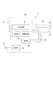
- FIG. 7 is a functional block diagram of the endoscope apparatus 1.
- the endoscope apparatus 1 stores an image processing unit 52 that processes a video signal acquired by the imaging mechanism 15 of the insertion unit 10, and an acquired still image, moving image, and the like.
- a storage unit 53 and a control unit 54 for controlling the entire operation of the endoscope apparatus 1 including adjustment of the light amount of the illumination mechanism 12 and the like are provided.
- the image processing unit 52 and the control unit 54 are stored in, for example, an IC (not shown) attached to the control board 42, for example.
- the storage unit 53 various known storage media can be used, and the storage unit 53 may be detachably attached to the housing unit 60.
- the imaging mechanism 15 and the illumination mechanism 12 are connected to the image processing unit 52 and the control unit 54 by a wiring 55 that extends through the insertion unit 10 and into the housing unit 60.
- the second joystick 22 of the operation unit 20 is electrically connected to the control unit 54 via a substrate or the like (not shown).
- the operation at the time of use of the endoscope apparatus 1 configured as described above will be described.
- the user activates the endoscope apparatus 1 with the battery B stored in the battery housing portion 74 and inserts the distal end of the insertion portion 10 into the inside of the test object or the access path to the test object. And proceed to the site to be observed.
- the insertion portion 10 When changing the direction of the distal end of the insertion portion 10, the insertion portion 10 is bent in a desired direction by operating the first joystick 21 of the operation portion 20 to advance and retract the operation member 14 connected to the bending mechanism 23.
- FIG. 6 shows an example of the positional relationship between the user's finger and the casing 60 during the operation.
- the forefinger F1 is located on the first slope 71 of the lower back surface 65B and the little finger F4 is located on the second slope 72 in a side view of the housing 61. Therefore, the connection part of the insertion part 10 and the housing
- casing part 60 is located between the index finger F1 and the little finger F4, and the insertion part 10 is extended from the back surface 65B which is a holding surface.
- the middle finger F2 is arranged on the first slope 71 in addition to the index finger F1
- the ring finger F3 is arranged on the second slope 72 in addition to the little finger F4.
- the distal end of the insertion unit 10 When the distal end of the insertion unit 10 reaches the observation target site, the user observes and inspects the test object while operating the operation unit 20. If necessary, the freeze / record button 71A is operated to record a still image, a moving image, or the like of the target part. The acquired various videos are stored in the storage unit 53.
- the housing 61 can be placed on the ground or a desk for operation.
- casing 61 becomes self-supporting suitably by making the upper part 64 into the lower side and the lower part 65 into the upper side.
- the proximal end portion of the insertion portion 10 extending from the housing 61 is linearly held by the reinforcing member 62, it is preferably self-supporting without the holder 63, but as shown in FIG.
- the grounding surface 63C is positioned on the grounding surface of the housing 61 defined by the connecting portion to be grounded and the grounding member 68.
- the holder 63 suitably assists the self-supporting of the housing 61, and the housing 61 can be placed in a more stable state.
- the state in which the casing 61 is placed in this manner and the endoscope apparatus 1 is used is referred to as “inverted mode”.
- the user When using the casing 61 as described above, the user inputs a predetermined operation via the operation unit 20 to switch the screen display mode.
- the display control unit 51 switches the display on the display 41 from the standard mode shown in FIG. 9A to a display mode corresponding to the inverted mode shown in FIG. 9B.
- FIG. 9A in the standard mode, an image acquired by the imaging means 15 is displayed in the first area R1, and character information such as an operation menu and various parameters is displayed in the second area R2.
- the inverted mode shown in FIG. 9B the user sees the display upside down. For this reason, the character information displayed in the second region R2 is displayed upside down from the standard mode.
- the top and bottom of the image displayed in the first region R1 is not reversed even in the inversion mode. This is to maintain the correspondence between the video and the operation of the first joystick 21.
- the freeze / record button 71A whether the video is recorded in either the standard mode or the inverted mode, the vertical relationship is unified and stored in the storage unit 53. is there.
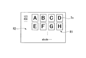
- the thumbnail screen showing a list of images stored in the storage unit 53 does not need to consider the above-described matters, and thus is inverted upside down and aligned in the first region R1 in the inverted mode shown in FIG. 10B. Displayed. As a result, the orientation of the thumbnail image Tn viewed by the user is the same as in the standard mode shown in FIG. 10A. Also, a retrieve screen (not shown) that displays one image corresponding to an arbitrary thumbnail image Tn selected from the thumbnail screen is displayed with the image turned upside down in the inverted mode.
- the first joystick 21 in the neutral state and the insertion portion 10 connected to the housing portion 60 are arranged so as to be coaxial.
- the mechanical bending mechanism 23 using the operation member 14 the amount of advancement / retraction of each operation member 14 during the bending operation becomes uniform, and the bending portion 13 can be bent appropriately.
- the 1st slope 71 and the 2nd slope 72 are the upper side and the lower side of the insertion part 10, respectively. Is formed.
- the back surface 65 ⁇ / b> B has a convex shape that rises toward the insertion portion 10 in a side view of the housing 61.
- the user's hand holding the lower portion 65 is in a state in which the palm side is concave and the back surface 65B is wrapped, and among the four fingers excluding the thumb, at least the first slope 71 and the second slope 72 One finger is placed, and the insertion portion 10 is sandwiched in the up-down direction.
- a force such as a moment that acts on the housing portion 60 by the long insertion portion 10 can be suitably received by the user's hand regardless of the direction in which it acts, and the housing 61 can be stabilized. Can be held.
- the user can suitably hold the housing portion 60 with a hand that holds the lower portion 65, Furthermore, the positions of the upper front surface 64A and the lower front surface 65A can be suitably stabilized. That is, it is difficult for the display unit 40 to be visually recognized and the operation unit 20 to be difficult to operate, such as the upper front 64A falling to the back side or the lower front 65A being parallel to the vertical direction. As a result, it is possible to perform the operation while holding the housing unit 60 in a state where the display 41 is easy to see and the operation unit 20 is easily operated.
- the swing center 21A of the first joystick 21 is the first where the user's finger is disposed when holding the housing 61 in a side view of the housing 61 shown in FIG. It is located within the area A2 defined by the inclined surface 71 and the second inclined surface 72, and the tip 21B of the first joystick 21 protruding to the front surface 65A. Therefore, it is possible to obtain an endoscope apparatus that is preferably prevented from being shaken by the amount of force acting on the housing part 60 when the first joystick 21 is operated, and is less fatigued even if operated for a long time. .
- the tip side of the finger (for example, the ring finger F3 and the little finger F4) arranged on the second inclined surface 72 holds the lower portion 65. In this case, it is disposed along one of the first holding surface 72A and the second holding surface 72B.
- the fingers F3, F4 and the like arranged on the second inclined surface 72 and the thumb Th are in a positional relationship substantially facing each other.
- the first joystick 21 is tilted by the thumb Th in a direction away from the hand such as the direction in which the thumb Th extends (for example, the direction of the arrow D1 shown in FIG.
- the first finger 21 is tilted by the ring finger F3, the little finger F4, It is possible to perform the operation while keeping the housing 61 in a stable state by suitably receiving the force that tilts the housing 61 acting in accordance with the operation.
- the 2nd slope 72 can arrange
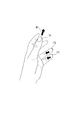
- FIG. 11 shows an example in which holding and operation are performed with the left hand.
- the tip side of the finger arranged on the second slope 72 is arranged on the second holding surface 72B.
- the tip side of the finger is disposed on the first holding surface 72A, but the first holding surface 72A and the second holding surface 72B are the center in the left-right direction of the housing 61. Since it is arranged symmetrically with respect to each other, the same effect is obtained.
- the friction member 73 having elasticity is attached to the first holding surface 72A and the second holding surface 72B, even when a relatively large amount of force acts on the finger disposed on the second inclined surface 72, The positional relationship between the two inclined surfaces 72 and the finger is preferably maintained. As a result, it is possible to perform the stable operation while suitably holding the casing 60 during the operation.
- the second joystick 22 protrudes from the bottom of the recess 70 provided in the lower surface 65A, and its height is set so that the tip does not protrude on the front surface 65A. Although it is arranged in a place where it can be easily operated with the thumb Th, the operation of the first joystick 21 is not hindered, and the operability can be further improved.
- the housing 61 is configured such that the upper portion 64 is on the lower side and the lower portion 65 is on the upper side by grounding the two ground members 68 provided on the upper portion 65 and the connecting portion between the insertion portion 10 and the housing portion.
- the display control unit 41 described above, the display on the display 41 is easy to see even when used in the inverted mode, and can be suitably used.
- the shape of the gripping surface in the present invention is not limited to the shape having the first slope and the second slope as described above, and may be any shape that is convex on the back side.
- the gripping surface 82 has a spindle shape that is convex on the back side.
- the portions corresponding to the first surface and the second surface are curved surfaces, but the finger can be suitably placed because it follows the curve of the user's finger to be held, and stable holding It can be performed.
- the hand Hd held with the first joystick 21 on the hand side and the display unit 40 on the hand side is indicated by a two-dot chain line. It is also possible to hold the unit 40 facing upward.
- FIG. 13 shows an endoscope apparatus 91 according to a modification of the present invention in which the gripping surface 92 is formed in a spherical shape. Since such a gripping surface 92 also follows the curvature of the user's finger F to be held as schematically shown in FIG. 14A, the finger F can be suitably disposed.
- the gripping surface 94 shown in FIG. 14B and the gripping surface 95 shown in FIG. 14C have first holding surfaces 94A and 95A and second holding surfaces 94B and 95B that rise from the edge in the left-right direction of the housing, respectively. Is convex on the back side in the bottom view. And the connection site
- the user can hang a part of the finger F (for example, the first joint) on the top portions 94C and 95C, and the holding can be further stabilized.
- the first holding surface 95A and the second holding surface 95B are curved with a predetermined curvature so as to be concave on the back surface side, but have a top portion 95C, so the basic shape of the gripping surface 95 is the back surface Convex to the side.
- FIG. 14D shows a gripping surface 96 having a convex portion 96B protruding on the spherical basic surface 96A. Even with such a gripping surface, the user can hang the first joint of the finger F on the convex portion 96B, and the holding can be stabilized.
- FIG. 14E shows a gripping surface 97 having a concave portion 97B on a spherical basic surface 97A.
- the user can stabilize the holding by placing the first joint of the finger F on the concave portion 97B.
- the concave portion 97B itself is not convex on the back surface side, but has a spherical basic surface 97A, and thus the basic shape is convex on the back surface side.
- the gripping surface can be appropriately set according to the use of the endoscope apparatus, the target user, or the like while having a basic shape that is convex on the back side.
- the gripping surface only needs to be convex on the back side in at least one of the side view and the bottom view of the housing, and is convex on the back side in both the side view and the bottom view as in the endoscope device 1. Even if it is not, it is effective to stabilize the holding by the user to some extent.
- the example in which the grounding member 68 for allowing the housing 61 to stand independently in the inverted mode is disposed at two spaced apart positions.
- the grounding member is the upper back surface 64B. May be arranged on a straight line at a certain length (for example, the extent of connecting two places where the grounding member 68 of the present embodiment is arranged). Even in this case, the housing 61 can be suitably used independently and used in the inverted mode.
- the example in which the illumination mechanism 12 is arranged at the distal end of the insertion portion 10 has been described.
- a light source is provided in the casing as in some conventional endoscope apparatuses.
- the light guide member such as a light guide may be disposed in the insertion portion to supply illumination light to the distal end of the insertion portion.
- the present invention is preferably applied to an endoscope apparatus that can use only a battery as a power source, but may be configured to be able to supply power from an external power source in addition to the battery.
- the position of the center of gravity of the endoscope apparatus excluding the insertion portion changes significantly without mounting the battery, it is the same size and size as the battery and is lighter than the battery.
- a dummy member capable of setting the position of the center of gravity within a predetermined region in a state of being mounted in the storage unit may be provided and used by being mounted on the battery storage unit when using an external power source.
- the friction member having elasticity is attached to the first holding surface and the second holding surface.
- the friction member one that does not elastically deform is selected, and this is used as each holding surface. Even if only the friction coefficient is increased, a certain effect can be obtained.
- the example in which the reinforcing member and the self-supporting auxiliary member are attached to the base end portion of the insertion portion connected to the housing has been described, but only one of the reinforcing member and the self-supporting auxiliary member is attached. Alternatively, none of them may be attached, and the endoscope apparatus may be configured to be able to stand on its own only by the connection part of the insertion part and the edge part on the display part side of the housing.
- the present invention can be widely applied to the observation of the test object at the tip of the elongated insertion path, the internal observation of the test object, and the like.
Abstract
Le dispositif d'endoscope (1) de l'invention est équipé : d'une partie d'insertion (10) flexible qui possède un mécanisme de prise de vue sur sa partie extrémité avant; d'une partie affichage qui affiche une image capturée à l'aide d'un moyen d'observation; d'une partie maniement destinée à manier de manière flexible la partie d'insertion; et d'un boîtier (61) dans lequel la partie affichage et une partie maniement sont logées côté face frontale, et la partie d'insertion est connectée du côté d'une face arrière s'opposant à la face frontale. La face arrière du boîtier possède un premier plan incliné (71) et un second plan incliné (72) s'élevant vers la partie insertion ainsi connectée. Le second plan incliné (72) possède une première face de maintien (72A) et une seconde face de maintien (72B) qui s'inclinent vers les deux extrémités du boîtier considéré dans sa direction horizontale.
Priority Applications (5)
| Application Number | Priority Date | Filing Date | Title |
|---|---|---|---|
| JP2011527534A JP4896273B1 (ja) | 2010-12-24 | 2010-12-24 | 内視鏡装置 |
| CN201080048934.2A CN102711581B (zh) | 2010-12-24 | 2010-12-24 | 内窥镜装置 |
| PCT/JP2010/073439 WO2012086083A1 (fr) | 2010-12-24 | 2010-12-24 | Dispositif d'endoscope |
| EP10858783.3A EP2489301B1 (fr) | 2010-12-24 | 2010-12-24 | Dispositif d'endoscope |
| US13/454,364 US8795160B2 (en) | 2010-12-24 | 2012-04-24 | Endoscope apparatus |
Applications Claiming Priority (1)
| Application Number | Priority Date | Filing Date | Title |
|---|---|---|---|
| PCT/JP2010/073439 WO2012086083A1 (fr) | 2010-12-24 | 2010-12-24 | Dispositif d'endoscope |
Related Child Applications (1)
| Application Number | Title | Priority Date | Filing Date |
|---|---|---|---|
| US13/454,364 Continuation US8795160B2 (en) | 2010-12-24 | 2012-04-24 | Endoscope apparatus |
Publications (1)
| Publication Number | Publication Date |
|---|---|
| WO2012086083A1 true WO2012086083A1 (fr) | 2012-06-28 |
Family
ID=45907960
Family Applications (1)
| Application Number | Title | Priority Date | Filing Date |
|---|---|---|---|
| PCT/JP2010/073439 WO2012086083A1 (fr) | 2010-12-24 | 2010-12-24 | Dispositif d'endoscope |
Country Status (5)
| Country | Link |
|---|---|
| US (1) | US8795160B2 (fr) |
| EP (1) | EP2489301B1 (fr) |
| JP (1) | JP4896273B1 (fr) |
| CN (1) | CN102711581B (fr) |
| WO (1) | WO2012086083A1 (fr) |
Cited By (3)
| Publication number | Priority date | Publication date | Assignee | Title |
|---|---|---|---|---|
| JP2015043084A (ja) * | 2013-08-26 | 2015-03-05 | ゼネラル・エレクトリック・カンパニイ | 検査または試験装置の能動冷却 |
| WO2015174128A1 (fr) * | 2014-05-16 | 2015-11-19 | オリンパス株式会社 | Endoscope |
| WO2021192269A1 (fr) * | 2020-03-27 | 2021-09-30 | オリンパス株式会社 | Unité d'actionnement d'endoscope et endoscope |
Families Citing this family (10)
| Publication number | Priority date | Publication date | Assignee | Title |
|---|---|---|---|---|
| WO2012151073A2 (fr) | 2011-05-03 | 2012-11-08 | Endosee Corporation | Procédé et appareil pour hystéroscopie et biopsie de l'endomètre |
| WO2012086065A1 (fr) | 2010-12-24 | 2012-06-28 | オリンパス株式会社 | Dispositif d'endoscope |
| JP4897116B1 (ja) | 2010-12-24 | 2012-03-14 | オリンパス株式会社 | 内視鏡装置 |
| EP2484270B1 (fr) | 2010-12-24 | 2014-03-12 | Olympus Corporation | Dispositif d'endoscope |
| US9468367B2 (en) | 2012-05-14 | 2016-10-18 | Endosee Corporation | Method and apparatus for hysteroscopy and combined hysteroscopy and endometrial biopsy |
| US9622646B2 (en) | 2012-06-25 | 2017-04-18 | Coopersurgical, Inc. | Low-cost instrument for endoscopically guided operative procedures |
| WO2016157578A1 (fr) * | 2015-03-31 | 2016-10-06 | オリンパス株式会社 | Endoscope rigide courbé |
| US10702305B2 (en) | 2016-03-23 | 2020-07-07 | Coopersurgical, Inc. | Operative cannulas and related methods |
| US11259688B2 (en) | 2018-04-18 | 2022-03-01 | Duke University | Devices for assisting manipulation of input mechanisms of medical instruments |
| US11253150B2 (en) * | 2018-06-14 | 2022-02-22 | Broadspot Imaging Corp | Visualization device with handed symmetry |
Citations (1)
| Publication number | Priority date | Publication date | Assignee | Title |
|---|---|---|---|---|
| JP2004109222A (ja) * | 2002-09-13 | 2004-04-08 | Olympus Corp | 内視鏡装置 |
Family Cites Families (46)
| Publication number | Priority date | Publication date | Assignee | Title |
|---|---|---|---|---|
| JPS5648241Y2 (fr) * | 1976-04-26 | 1981-11-11 | ||
| JPS595901U (ja) * | 1982-07-02 | 1984-01-14 | 株式会社町田製作所 | 内視鏡の柄部 |
| JPS628727A (ja) * | 1985-07-03 | 1987-01-16 | 株式会社町田製作所 | 内視鏡 |
| US4742819A (en) | 1987-03-23 | 1988-05-10 | George Gordon P | Intubating scope with camera and screen |
| JPH0490743A (ja) | 1990-08-02 | 1992-03-24 | Olympus Optical Co Ltd | 内視鏡装置 |
| US5183031A (en) | 1991-05-13 | 1993-02-02 | Rossoff Leonard J | Fiberoptic intubating laryngoscope |
| JP3030348B2 (ja) | 1993-01-29 | 2000-04-10 | 富士写真光機株式会社 | 電子内視鏡 |
| USD358471S (en) | 1993-03-11 | 1995-05-16 | Welch Allyn, Inc. | Combined control handle and viewing screen for an endoscope |
| US5373317B1 (en) * | 1993-05-28 | 2000-11-21 | Welch Allyn Inc | Control and display section for borescope or endoscope |
| DE69426057T2 (de) | 1993-11-29 | 2001-05-10 | Olympus Optical Co | Anordnung zur Bildrotation und Überlagerung |
| WO1997015144A1 (fr) | 1995-10-20 | 1997-04-24 | Urohealth Systems, Inc. | Imageur a main a utiliser avec des endoscopes |
| FR2740688B1 (fr) | 1995-11-07 | 1997-12-12 | Tokendo Sarl | Sonde videoendoscopique souple a poignee de commande motorisee |
| US5785644A (en) | 1996-07-12 | 1998-07-28 | Circon Corporation | Pivotal handle assembly for a video operating laparoscope |
| US6432046B1 (en) | 1996-07-15 | 2002-08-13 | Universal Technologies International, Inc. | Hand-held, portable camera for producing video images of an object |
| US6554765B1 (en) | 1996-07-15 | 2003-04-29 | East Giant Limited | Hand held, portable camera with adaptable lens system |
| FR2785132B1 (fr) | 1998-10-27 | 2000-12-22 | Tokendo Sarl | Sonde videoendoscopique a capteur ccd couleur distal |
| US6569086B2 (en) | 2000-03-27 | 2003-05-27 | Olympus Optical Co., Ltd. | Controllable bending endoscope |
| US7179223B2 (en) | 2002-08-06 | 2007-02-20 | Olympus Optical Co., Ltd. | Endoscope apparatus having an internal channel |
| JP2004065832A (ja) | 2002-08-09 | 2004-03-04 | Pentax Corp | 電子内視鏡装置 |
| EP1441530B1 (fr) | 2003-01-17 | 2010-04-28 | Tokendo | Vidéoendoscope |
| JP4530642B2 (ja) | 2003-10-31 | 2010-08-25 | オリンパス株式会社 | 内視鏡装置 |
| JP4451124B2 (ja) | 2003-11-28 | 2010-04-14 | オリンパス株式会社 | 内視鏡用処置具挿抜システム |
| WO2005077252A1 (fr) | 2004-02-16 | 2005-08-25 | Olympus Corporation | Dispositif endoscopique |
| JP2005224521A (ja) | 2004-02-16 | 2005-08-25 | Olympus Corp | 内視鏡装置 |
| US8465442B2 (en) * | 2004-05-13 | 2013-06-18 | Boston Scientific Scimed, Inc. | Handle for steerable catheter |
| US7584534B2 (en) | 2005-01-10 | 2009-09-08 | Perceptron, Inc. | Remote inspection device |
| JP4776933B2 (ja) | 2005-01-28 | 2011-09-21 | オリンパス株式会社 | 内視鏡装置 |
| USD533939S1 (en) * | 2005-02-23 | 2006-12-19 | Optim, Inc. | Control handle with a display for an endoscopic device |
| US7956888B2 (en) | 2005-06-22 | 2011-06-07 | Ge Inspection Technologies, Lp | Remote video inspection system integrating audio communication functionality |
| EP1909633B1 (fr) | 2005-06-24 | 2011-11-23 | GE Inspection Technologies, LP | Carrousel de rangement pour tube d'insertion |
| JP4761928B2 (ja) | 2005-10-24 | 2011-08-31 | Hoya株式会社 | 挿管支援装置 |
| US7679041B2 (en) | 2006-02-13 | 2010-03-16 | Ge Inspection Technologies, Lp | Electronic imaging device with photosensor arrays |
| JP5030441B2 (ja) | 2006-03-09 | 2012-09-19 | オリンパスメディカルシステムズ株式会社 | 内視鏡装置 |
| US20070270647A1 (en) * | 2006-05-19 | 2007-11-22 | Ams Research Corporation | Handle for Multifunction Endoscope |
| USD581051S1 (en) * | 2006-06-30 | 2008-11-18 | Envisionier Medical Technologies Llc | Camera |
| JP2008011992A (ja) | 2006-07-04 | 2008-01-24 | Olympus Medical Systems Corp | 内視鏡 |
| US8106856B2 (en) | 2006-09-06 | 2012-01-31 | Apple Inc. | Portable electronic device for photo management |
| USD560804S1 (en) | 2006-09-22 | 2008-01-29 | Perceptron, Inc. | Display housing for remote inspection device |
| JP2009189685A (ja) * | 2008-02-18 | 2009-08-27 | Hoya Corp | 内視鏡 |
| CN102017622B (zh) | 2008-03-07 | 2015-08-26 | 密尔沃基电动工具公司 | 视觉检测装置 |
| CN201445509U (zh) * | 2009-07-03 | 2010-05-05 | 朱俭 | 一种带相机手柄和护套的内窥镜 |
| EP2484270B1 (fr) | 2010-12-24 | 2014-03-12 | Olympus Corporation | Dispositif d'endoscope |
| WO2012086065A1 (fr) | 2010-12-24 | 2012-06-28 | オリンパス株式会社 | Dispositif d'endoscope |
| JP4897116B1 (ja) | 2010-12-24 | 2012-03-14 | オリンパス株式会社 | 内視鏡装置 |
| US8182416B1 (en) | 2011-08-02 | 2012-05-22 | Olympus Corporation | Endoscopic device |
| US8177710B1 (en) | 2011-08-02 | 2012-05-15 | Olympus Corporation | Endoscopic device |
-
2010
- 2010-12-24 JP JP2011527534A patent/JP4896273B1/ja active Active
- 2010-12-24 CN CN201080048934.2A patent/CN102711581B/zh active Active
- 2010-12-24 WO PCT/JP2010/073439 patent/WO2012086083A1/fr active Application Filing
- 2010-12-24 EP EP10858783.3A patent/EP2489301B1/fr not_active Not-in-force
-
2012
- 2012-04-24 US US13/454,364 patent/US8795160B2/en active Active
Patent Citations (1)
| Publication number | Priority date | Publication date | Assignee | Title |
|---|---|---|---|---|
| JP2004109222A (ja) * | 2002-09-13 | 2004-04-08 | Olympus Corp | 内視鏡装置 |
Cited By (4)
| Publication number | Priority date | Publication date | Assignee | Title |
|---|---|---|---|---|
| JP2015043084A (ja) * | 2013-08-26 | 2015-03-05 | ゼネラル・エレクトリック・カンパニイ | 検査または試験装置の能動冷却 |
| WO2015174128A1 (fr) * | 2014-05-16 | 2015-11-19 | オリンパス株式会社 | Endoscope |
| JPWO2015174128A1 (ja) * | 2014-05-16 | 2017-04-20 | オリンパス株式会社 | 内視鏡 |
| WO2021192269A1 (fr) * | 2020-03-27 | 2021-09-30 | オリンパス株式会社 | Unité d'actionnement d'endoscope et endoscope |
Also Published As
| Publication number | Publication date |
|---|---|
| CN102711581A (zh) | 2012-10-03 |
| US20120209066A1 (en) | 2012-08-16 |
| EP2489301A1 (fr) | 2012-08-22 |
| JP4896273B1 (ja) | 2012-03-14 |
| JPWO2012086083A1 (ja) | 2014-05-22 |
| EP2489301B1 (fr) | 2014-07-30 |
| EP2489301A4 (fr) | 2012-11-14 |
| US8795160B2 (en) | 2014-08-05 |
| CN102711581B (zh) | 2014-01-29 |
Similar Documents
| Publication | Publication Date | Title |
|---|---|---|
| JP4897117B1 (ja) | 内視鏡装置 | |
| JP4896272B1 (ja) | 内視鏡装置 | |
| JP4897116B1 (ja) | 内視鏡装置 | |
| JP4896273B1 (ja) | 内視鏡装置 | |
| US8182416B1 (en) | Endoscopic device | |
| US8177710B1 (en) | Endoscopic device | |
| US20080207998A1 (en) | Endoscope apparatus | |
| WO2011068000A1 (fr) | Endoscope sans fil portatif | |
| JP2006192201A (ja) | 電動湾曲内視鏡装置 | |
| JP2009189685A (ja) | 内視鏡 | |
| JP2011067256A (ja) | 内視鏡装置 | |
| JP2013034546A (ja) | 内視鏡 | |
| JP6315800B2 (ja) | 内視鏡 | |
| JP5749564B2 (ja) | 内視鏡装置 | |
| JP2001272609A (ja) | 内視鏡用操作リモートコントローラ | |
| JP6266173B2 (ja) | 携帯型内視鏡 | |
| JP2015147097A (ja) | 内視鏡装置 | |
| JP2005175843A (ja) | ビデオカメラ |
Legal Events
| Date | Code | Title | Description |
|---|---|---|---|
| WWE | Wipo information: entry into national phase |
Ref document number: 201080048934.2 Country of ref document: CN |
|
| WWE | Wipo information: entry into national phase |
Ref document number: 2011527534 Country of ref document: JP |
|
| WWE | Wipo information: entry into national phase |
Ref document number: 2010858783 Country of ref document: EP |
|
| 121 | Ep: the epo has been informed by wipo that ep was designated in this application |
Ref document number: 10858783 Country of ref document: EP Kind code of ref document: A1 |
|
| NENP | Non-entry into the national phase |
Ref country code: DE |