WO2012081700A1 - 構造物製造方法及び構造物製造装置 - Google Patents
構造物製造方法及び構造物製造装置 Download PDFInfo
- Publication number
- WO2012081700A1 WO2012081700A1 PCT/JP2011/079210 JP2011079210W WO2012081700A1 WO 2012081700 A1 WO2012081700 A1 WO 2012081700A1 JP 2011079210 W JP2011079210 W JP 2011079210W WO 2012081700 A1 WO2012081700 A1 WO 2012081700A1
- Authority
- WO
- WIPO (PCT)
- Prior art keywords
- camera
- positioning
- image
- hole
- rear spar
- Prior art date
- Legal status (The legal status is an assumption and is not a legal conclusion. Google has not performed a legal analysis and makes no representation as to the accuracy of the status listed.)
- Ceased
Links
Images



Classifications
-
- B—PERFORMING OPERATIONS; TRANSPORTING
- B23—MACHINE TOOLS; METAL-WORKING NOT OTHERWISE PROVIDED FOR
- B23P—METAL-WORKING NOT OTHERWISE PROVIDED FOR; COMBINED OPERATIONS; UNIVERSAL MACHINE TOOLS
- B23P19/00—Machines for simply fitting together or separating metal parts or objects, or metal and non-metal parts, whether or not involving some deformation; Tools or devices therefor so far as not provided for in other classes
- B23P19/10—Aligning parts to be fitted together
-
- H—ELECTRICITY
- H04—ELECTRIC COMMUNICATION TECHNIQUE
- H04N—PICTORIAL COMMUNICATION, e.g. TELEVISION
- H04N23/00—Cameras or camera modules comprising electronic image sensors; Control thereof
- H04N23/50—Constructional details
- H04N23/54—Mounting of pick-up tubes, electronic image sensors, deviation or focusing coils
-
- B—PERFORMING OPERATIONS; TRANSPORTING
- B64—AIRCRAFT; AVIATION; COSMONAUTICS
- B64C—AEROPLANES; HELICOPTERS
- B64C3/00—Wings
- B64C3/18—Spars; Ribs; Stringers
-
- B—PERFORMING OPERATIONS; TRANSPORTING
- B64—AIRCRAFT; AVIATION; COSMONAUTICS
- B64F—GROUND OR AIRCRAFT-CARRIER-DECK INSTALLATIONS SPECIALLY ADAPTED FOR USE IN CONNECTION WITH AIRCRAFT; DESIGNING, MANUFACTURING, ASSEMBLING, CLEANING, MAINTAINING OR REPAIRING AIRCRAFT, NOT OTHERWISE PROVIDED FOR; HANDLING, TRANSPORTING, TESTING OR INSPECTING AIRCRAFT COMPONENTS, NOT OTHERWISE PROVIDED FOR
- B64F5/00—Designing, manufacturing, assembling, cleaning, maintaining or repairing aircraft, not otherwise provided for; Handling, transporting, testing or inspecting aircraft components, not otherwise provided for
- B64F5/10—Manufacturing or assembling aircraft, e.g. jigs therefor
-
- H—ELECTRICITY
- H04—ELECTRIC COMMUNICATION TECHNIQUE
- H04N—PICTORIAL COMMUNICATION, e.g. TELEVISION
- H04N5/00—Details of television systems
- H04N5/222—Studio circuitry; Studio devices; Studio equipment
- H04N5/262—Studio circuits, e.g. for mixing, switching-over, change of character of image, other special effects ; Cameras specially adapted for the electronic generation of special effects
- H04N5/265—Mixing
-
- B—PERFORMING OPERATIONS; TRANSPORTING
- B23—MACHINE TOOLS; METAL-WORKING NOT OTHERWISE PROVIDED FOR
- B23P—METAL-WORKING NOT OTHERWISE PROVIDED FOR; COMBINED OPERATIONS; UNIVERSAL MACHINE TOOLS
- B23P2700/00—Indexing scheme relating to the articles being treated, e.g. manufactured, repaired, assembled, connected or other operations covered in the subgroups
- B23P2700/01—Aircraft parts
-
- Y—GENERAL TAGGING OF NEW TECHNOLOGICAL DEVELOPMENTS; GENERAL TAGGING OF CROSS-SECTIONAL TECHNOLOGIES SPANNING OVER SEVERAL SECTIONS OF THE IPC; TECHNICAL SUBJECTS COVERED BY FORMER USPC CROSS-REFERENCE ART COLLECTIONS [XRACs] AND DIGESTS
- Y10—TECHNICAL SUBJECTS COVERED BY FORMER USPC
- Y10T—TECHNICAL SUBJECTS COVERED BY FORMER US CLASSIFICATION
- Y10T29/00—Metal working
- Y10T29/49—Method of mechanical manufacture
- Y10T29/49826—Assembling or joining
- Y10T29/49895—Associating parts by use of aligning means [e.g., use of a drift pin or a "fixture"]
-
- Y—GENERAL TAGGING OF NEW TECHNOLOGICAL DEVELOPMENTS; GENERAL TAGGING OF CROSS-SECTIONAL TECHNOLOGIES SPANNING OVER SEVERAL SECTIONS OF THE IPC; TECHNICAL SUBJECTS COVERED BY FORMER USPC CROSS-REFERENCE ART COLLECTIONS [XRACs] AND DIGESTS
- Y10—TECHNICAL SUBJECTS COVERED BY FORMER USPC
- Y10T—TECHNICAL SUBJECTS COVERED BY FORMER US CLASSIFICATION
- Y10T29/00—Metal working
- Y10T29/53—Means to assemble or disassemble
- Y10T29/53978—Means to assemble or disassemble including means to relatively position plural work parts
Definitions
- the present invention relates to a structure manufacturing method and a structure manufacturing apparatus for manufacturing a structure by assembling a pair of members.
- this positioning method a method using a so-called downward swing in which a weight is attached to one end of a thread has been conventionally used.
- this downward swing first, positioning holes are formed at locations where the positions of both members are to be aligned.
- the members are arranged apart from each other in the vertical direction, and a thread for swinging down is inserted through the hole of the member positioned above, so that the weight is suspended vertically downward.
- one member is lowered toward the other member or the other member is raised toward the one member while keeping the weight so as to match the position of the hole of the member located below.
- a pair of member can be positioned correctly by making the hole of one member and the hole of the other member correspond.
- the positioning using this downward swing is used as a positioning means that is particularly effective when the surface of each member is a curved surface. This is because when the positioning holes are formed orthogonally to the curved surface, the axial direction of the hole does not match between one member and the other member vertically below, and the other member passes through the hole of one member. This is because the hole of the member cannot be seen.
- an example of a structure is an aircraft structure such as an aircraft main wing.
- the present applicant has conventionally proposed an aircraft structure manufacturing apparatus that can raise or lower one member toward the other member with high accuracy (see Patent Document 1).
- both the members are not accurately positioned and the positioning work is re-executed. More specifically, when using a downward swing, one of the members is lowered or raised in a state where the weight is located between the one member and the other member. Therefore, in order to prevent the weight from interfering with each member, it is necessary to remove the downward swing from between both members immediately before the two members come in contact with each other. Will be raised. As a result, an error may occur in the positioning of both members depending on the skill of the operator, and in this case, the positioning operation will be redone.
- the present invention has been made in consideration of such circumstances, and its purpose is to position the pair of members with high accuracy by a simple operation when the structure is manufactured by assembling the pair of members.
- the object is to provide a method for manufacturing a structure.
- the structure manufacturing method is a structure manufacturing method for manufacturing a structure by assembling so that the members in which holes are respectively formed are relatively moved to match the holes.
- the members are relatively moved while aligning the image of the hole acquired by the imaging means and displayed on the monitor screen with the marking on the monitor screen.
- the members can be positioned with high accuracy.
- the cost can be reduced by reducing the labor cost.
- the image of the hole in one member is reliably acquired by the imaging means installed in the other member. be able to. Thereby, accurate positioning of members becomes possible.
- the imaging means acquires an image of the hole formed in one member through the hole formed in the other member.
- an image of a hole formed in one member can be reliably acquired with a simple configuration using a positioning hole.
- the structure is a wing body of an aircraft, and the one member is a panel member that forms an outer surface of the wing body, and the other This is a girder member disposed in the longitudinal direction of the wing body.
- the panel member and the girder member are raised by a simple operation by one operator. Positioning can be performed with accuracy.
- the relative position of the side surfaces of the members is positioned at the tip of the wing body. A positioning step.
- the proximal end side is aligned with respect to the hole and the distal end side is positioned with respect to the side surface.
- the panel member and the girder member can be positioned with high accuracy over the entire structure.
- the structure manufacturing apparatus which concerns on the 5th aspect of this invention is the structure manufacturing apparatus which manufactures a structure by assembling so that the members in which each hole was each formed may be relatively moved, and the said holes may be matched.
- An imaging unit that is attached to one member and obtains an image of the hole formed in the other member, and a marking to align the other member set in advance with respect to the image of the hole
- a composite image generating unit that generates a composite image by combining the information, and a display unit that displays the composite image.
- the composite image generating unit combines the preset marking information with the hole image acquired by the imaging unit, thereby combining the composite image. Is generated.
- This composite image is displayed on the display means.
- the members can be positioned with high accuracy by a simple operation of relatively moving the members while aligning the hole image with the marking.
- the cost can be reduced by reducing the labor cost.
- the image of the hole in one member is reliably acquired by the imaging means installed in the other member. be able to. Thereby, accurate positioning of members becomes possible.
- the pair of members when a pair of members are assembled to manufacture a structure, the pair of members can be positioned with high accuracy by a simple operation.
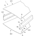
- FIG. 1 It is a disassembled perspective view which shows schematic structure of the main wing which concerns on embodiment of this invention. It is the perspective view which showed the base end part of the main wing typically. It is sectional drawing which showed the front-end
- FIG. 1 is an exploded perspective view showing a schematic configuration of the main wing 1.
- the main wing 1 includes a pair of spars 2 (girder members) that form both sides along the longitudinal direction, a pair of panels 3 that form the upper surface and the lower surface thereof, and a plurality of ribs 4 provided in the interior. Prepare.
- the pair of spar 2 includes a front spar 21 that forms a side portion on the front side of the aircraft among both side portions of the main wing 1, and a rear spar 22 that forms a side portion on the rear side of the aircraft.
- FIG. 2 is a perspective view schematically showing the base end portion of the main wing 1, that is, the end portion on the aircraft fuselage side.
- the rib 4 is not shown.
- Each of the front spar 21 and the rear spar 22 is a longitudinal member having a substantially U-shaped cross section, and a pair of parallel pieces 22a that are substantially parallel to each other at a predetermined interval, and a connection piece 22b that connects one end of the parallel piece 22a. ,have.
- shooting holes 22 c are formed through the pair of parallel pieces 22 a vertically.
- the pair of spar 2 configured as described above is arranged at a predetermined interval so that the respective opening portions face each other.
- the pair of panels 3 includes an upper panel 31 that forms the upper surface of the main wing 1 and a lower panel 32 that forms the lower surface.
- the upper panel 31 and the lower panel 32 each have a panel main body 3a having a curved cross-sectional shape, and a plurality of stringers 3b provided on one surface of the panel main body 3a so as to extend in the longitudinal direction. ing.
- the panel body 3a of the upper panel 31 has a substantially trapezoidal shape in which the width gradually decreases from the base end side toward the front end side in a plan view, and at the base end portion thereof.
- a target hole 33 is formed at a position corresponding to the shooting hole 22c of the rear spar 22 through the panel body 3a vertically.
- the panel body 3a of the lower panel 32 has substantially the same shape as the panel body 3a of the upper panel 31 in a plan view, and at a position corresponding to the shooting hole 22c of the rear spar 22 at the base end portion thereof,
- a target hole 34 is formed through the panel body 3a vertically.
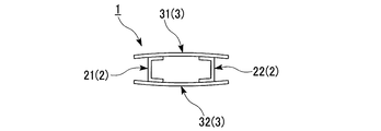
- the stringer 3b is for increasing the bending rigidity of the upper panel 31 and the lower panel 32, and has a substantially H-shaped cross section as shown in FIG.
- FIG. 3 is a cross-sectional view schematically showing the tip of the main wing 1, that is, the end opposite to the fuselage of the aircraft. At the tip of the main wing 1, both ends in the width direction of the upper panel 31 and the lower panel 32 protrude outward from the pair of spar 2 by a predetermined distance.
- the plurality of ribs 4 are members for structurally reinforcing the main wing 1. As shown in FIG. 1, the ribs 4 are provided at predetermined intervals in the longitudinal direction of the main wing 1, and one end of each rib 4 is connected to the front spar 21 and the other end is connected to the rear spar 22. As a result, the front spar 21 and the rear spar 22 are held at regular intervals.
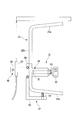
- FIG. 4 is a schematic front view showing the configuration of the main wing manufacturing apparatus 10.
- the main wing manufacturing apparatus 10 includes a first positioning device 11 that positions the rear spar 22 and the upper panel 31 that constitute the main wing 1, a second positioning device 12 that positions the rear spar 22 and the lower panel 32, and the main wing 1. And an assembling device 13 for assembling various members constituting the.
- the first positioning device 11 includes a proximal end camera unit 14 installed at the proximal end portion of the rear spar 22 constituting the main wing 1, a distal end camera unit 15 installed at the distal end portion of the rear spar 22, and a proximal end camera. And a monitor screen 16 (display means) electrically connected to the unit 14 and the front end camera unit 15 through wiring.
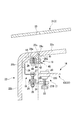
- FIG. 5 is a schematic cross-sectional view showing a state in which the proximal camera unit 14 is attached to the rear spar 22.
- the proximal end camera unit 14 and the distal end camera unit 15 are installed at the proximal end and the distal end of the rear spar 22, respectively, but instead, at the proximal end and the distal end of the front spar 21, respectively. Each may be installed.
- the base end camera unit 14 includes a clamp portion 17 that is fixed to the rear spar 22, a positioning portion 18 that is positioned with respect to the inner surface of the rear spar 22, and a camera holding portion 19 that holds the camera. And comprising.
- the clamp portion 17 includes a contact piece 20 that contacts the rear spar 22, a shaft 210 that is screwed to the contact piece 20, and a pressing member 220 that is provided at one end of the shaft 210. And a first operation knob 23 provided at the other end of the shaft 210, and a protruding piece 24 protruding from the contact piece 20 and extending laterally.
- the first operation knob 23 when the first operation knob 23 is picked and rotated, the shaft 210 moves forward and backward with respect to the contact piece 20, and the pressing member 220 and the contact piece 20 are thus moved. The interval between and changes. Accordingly, the camera unit can be attached to the rear spar 22 by sandwiching a predetermined portion of the rear spar 22 between the pressing member 220 and the contact piece 20.
- the positioning portion 18 includes a bolt 25 screwed to the projecting piece 24, a second operation knob 26 fixed to the shaft portion of the bolt 25, and a shaft portion of the bolt 25. And a reference block 29 fixed to the nut 27 via a support bracket 28. According to the positioning portion 18 configured as described above, when the bolt 25 is rotated by turning the second operation knob 26, the nut 27 screwed to the nut 25 moves along the shaft portion of the bolt 25. Thereby, the reference block 29 fixed to the nut 27 can be moved in the vertical direction.
- the reference block 29 includes a first reference surface 29 a that is in contact with the parallel piece 22 a of the rear spar 22, a second reference surface 29 b that is in contact with the connection piece 22 b of the rear spar 22, It has a convex portion 29c that protrudes from the reference surface 29a, and a camera insertion hole 29d for allowing the camera to pass therethrough.
- the angle formed by the first reference surface 29a and the second reference surface 29b is formed substantially equal to the angle formed by the parallel piece 22a and the connection piece 22b of the rear spar 22.
- the cross-sectional shape of the convex portion 29c is formed so as to substantially match the cross-sectional shape of the photographing hole 22c formed in the parallel piece 22a.
- the camera holding unit 19 has a camera holder 40 attached to the reference block 29 of the positioning unit 18 and a camera 41 (imaging means) held by the camera holder 40.
- the camera holder 40 is provided with a camera fixing hole 42 for fixing the camera 41, a fixing screw 43 for fixing to the reference block 29, and protruding on both sides with the fixing screw 43 interposed therebetween.
- the camera holder 40 configured as described above is positioned by inserting a pair of positioning pins 44 into the reference block 29, and then the fixing screw 43 is screwed into the reference block 29. It is fixed to the inner surface.
- the camera 41 has an elongated shape with a substantially circular cross section as shown in FIG.
- the camera 41 is inserted and fixed in the camera fixing hole 42 of the camera holder 40. Further, the camera 41 protrudes to the back side of the camera holder 40 and is inserted into the camera insertion hole 29d and the convex portion 29c of the reference block 29 and protrudes into the photographing hole 22c formed in the parallel piece 22a of the rear spar 22. Thus, it is in a state of facing vertically upward.
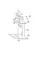
- FIG. 6 is a schematic perspective view for explaining the attachment of the camera 41 to the camera holder 40.
- the camera reference position confirmation device 45 includes a lower base 45a, a leg portion 45b extending upward from the lower base 45a, and an upper base 45c provided substantially parallel to the lower base 45a at the upper end of the leg portion 45b.
- the upper base 45 c is formed with a camera insertion hole 45 d through which the camera 41 can be inserted, and a fixing screw hole 45 e for fixing the fixing screw 43.
- a pair of pin holes 45g for inserting the pair of positioning pins 44 are formed on both sides of the fixing screw hole 45e.
- a cross-shaped reference line 45f is displayed on the lower base 45a, and the intersection of the reference lines 45f is separated from the center line of the camera insertion hole 45d by a predetermined distance in the horizontal direction.
- a target line indicating a position where the reference line 45f is to be displayed is displayed in advance on the monitor screen. Accordingly, if the camera 41 is appropriately rotated inside the camera fixing hole 42 and the camera insertion hole 45d to align the image of the reference line 45f with the target line and then the position of the camera 41 is fixed, the camera 41 is in an appropriate state. Can be attached to the camera holder 40.
- FIG. 7 is a schematic cross-sectional view showing a state in which the tip camera unit 15 is attached to the rear spar 22.
- the front end camera unit 15 includes a clamp portion 46 fixed to the rear spar 22, a positioning portion 47 positioned with respect to the outer surface of the rear spar 22, and a camera holding portion 48 that holds the camera 57.
- the clamp portion 46 includes an abutment piece 49 that abuts on the outer surface of the connection piece 22 b constituting the rear spar 22, a shaft 50 that is screwed to the abutment piece 49, and the shaft 50.
- a pressing member 51 provided at one end and a first operation knob 52 provided at the other end of the shaft 50 are provided.
- the shaft 50 moves forward and backward with respect to the contact piece 49, and the pressing member 51 and the contact piece 49. The interval between and changes.
- the front end camera unit 15 can be attached to the rear spar 22 by sandwiching a predetermined portion of the rear spar 22 between the pressing member 51 and the contact piece 49.
- the positioning portion 47 includes an L-shaped reference block 53 provided so as to be able to advance and retreat along the connection piece 22 b of the rear spar 22, and a positioning provided so as to protrude inward from the reference block 53. And a protrusion 54.
- the camera holding unit 48 includes a camera holder 56 attached to the reference block 53 of the positioning unit 47, and a camera 57 (imaging means) that is inserted and fixed in the camera holder 56 and faces vertically upward.
- a camera 57 imaging means
- the above-described camera reference position confirmation device 45 is used.
- the second positioning device 12 shown in FIG. 4 includes a proximal end camera unit 58 installed at the proximal end of the rear spar 22, a distal end camera unit 59 installed at the distal end of the rear spar 22, and a proximal end camera unit. 58 and a front end camera unit 59, and a monitor screen 16 (display means) electrically connected to each other via wiring.
- a proximal end camera unit 58 installed at the proximal end of the rear spar 22
- a distal end camera unit 59 installed at the distal end of the rear spar 22
- display means display means
- the assembly apparatus 13 shown in FIG. 4 includes an upper panel adsorbing part 131, an upper elevating stand 132, a lower panel supporting part 133, a lower elevating stand 134, a front spar holding part 135, a rear spar holding part 136, A transport unit 137 and an operation panel 138 are provided.
- the upper panel suction part 131 is a member that sucks and holds the upper panel 31 constituting the main wing 1.
- the upper lifting / lowering stand 132 controls the operation of the upper panel 31 held by the upper panel suction portion 131. More specifically, the upper lifting / lowering stand 132 has a biaxial direction, a vertical direction, and a vertical axis orthogonal to each other in a horizontal plane. The upper panel 31 can be arbitrarily moved in the direction of rotation around.
- the lower panel support part 133 is a member that supports the lower panel 32 constituting the main wing 1 from below.
- the lower elevating stand 134 controls the operation of the lower panel 32 supported by the lower panel support 133, and moves the upper panel 31 in the four-axis direction in the same manner as the upper elevating stand 132. be able to.
- the front spar holding part 135 and the rear spar holding part 136 are members that hold the front spar 21 and the rear spar 22 constituting the main wing 1 from the side so that their openings face each other.
- the front spar holding part 135 and the rear spar holding part 136 are provided so as to be able to advance and retreat in the horizontal direction.
- the conveyance unit 137 is a member that is provided so as to be able to travel in a direction substantially orthogonal to the paper surface of FIG. 4 and that carries in or out the lower panel support unit 133 in a state in which the lower panel 32 is supported.
- the operation panel 138 is a member for operating the operation of each part of the assembling apparatus 13.
- a monitor screen 16 constituting the first positioning device 11 and the second positioning device 12 is installed. Thereby, the operator can operate each part of the assembling apparatus 13 appropriately by operating the operation panel 138 while looking at the monitor screen 16.
- FIG. 8 is a block diagram showing a functional configuration of the main wing manufacturing apparatus 10.
- the main wing manufacturing apparatus 10 includes cameras 41 and 57 (imaging means), a storage means 60, a composite image generation means 61, and a monitor screen 16 (display means).
- the camera 41 is a member that acquires images of the target holes 33 and 34 formed in the upper panel 31 and the lower panel 32, respectively.
- the storage means 60 is a member that stores in advance target line information 62 (marking information) for positioning the upper panel 31 and the lower panel 32.
- the composite image generation unit 61 is a member that generates a composite image by combining the image input from the camera 41 and the target line information 62 input from the storage unit 60.
- the monitor screen 16 is a member that displays the composite image generated by the composite image generation means 61.
- information for displaying a line is used as marking information according to the present invention.
- the present invention is not limited to this, and information for displaying a point or information for displaying other figures may be used.
- the worker performs an imaging means installation process for installing the camera 41 on the rear spar 22. That is, the operator installs the proximal end camera unit 14 constituting the first positioning device 11 at the proximal end portion of the rear spar 22 and the distal end camera unit 15 at the distal end portion of the rear spar 22. More specifically, as shown in FIG. 5, the proximal end camera unit is formed by sandwiching a projecting piece 63 projecting from the inner surface of the rear spar 22 with a clamp portion 17 of the proximal end camera unit 14. 14 is temporarily fixed to the rear spar 22.
- the first reference surface 29a is set to the parallel piece 22a and the second reference surface 29b is set to the connection piece 22b. And contact each other.
- the projection 29c protruding from the first reference surface 29a is fitted into the shooting hole 22c formed in the parallel piece 22a.
- the second reference surface 29b is adjusted in advance so as to contact the connecting piece 22b by attaching a predetermined number of plate-like shims having a predetermined thickness. ing.
- the operator holds the connecting piece 22 b of the rear spar 22 by the clamp part 46 of the front end camera unit 15 and accurately positions the front end camera unit 15 with respect to the rear spar 22.
- the camera 57 held by the camera holding part 48 is in a state of facing vertically upward.
- proximal end camera unit 58 and the distal end camera unit 59 constituting the second positioning device 12 are also installed at the proximal end portion and the distal end portion of the rear spar 22 in the same manner as the first positioning device 11.
- the worker performs a spar installation process in which the rear spar 22 and the front spar 21 are installed. That is, as shown in FIG. 4, the worker holds the front spar 21 by the front spar holding part 135 and holds the rear spar 22 by the rear spar holding part 136. Then, with the front spar holding part 135 slightly retracted away from the rear spar holding part 136, one end of the rib 4 is fixed to the rear spar 22, and the front spar holding part 135 is advanced to move the other end of the rib 4 to the front. Fix to the spar 21. Thereby, the front spar 21 and the rear spar 22 are integrated via the rib 4. In the state where the rear spar 22 is held by the rear spar holding portion 136, the photographing hole 22c shown in FIG. 5 formed in the rear spar 22 is in a state where the axis thereof is inclined with respect to the vertical direction.
- the operator performs a positioning step of positioning the upper panel 31 and the lower panel 32 with respect to the rear spar 22 and the front spar 21 respectively. That is, as shown in FIG. 4, the operator operates the operation panel 138 and drives the upper lifting stand 132 with the upper panel 31 held by the upper panel suction unit 131, thereby moving the upper panel 31 substantially vertically. Lower downward.
- the target hole 34 shown in FIG. 5 formed in the upper panel 31 is in a state where the axis thereof is inclined with respect to the vertical direction.
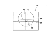
- FIG. 9A is a diagram showing a composite image displayed on the monitor screen 16.
- an image acquired by the camera 41 of the proximal end camera unit 14 constituting the first positioning device 11, that is, an image of the target hole 34 formed in the upper panel 31 is displayed, and a storage unit 60.
- a total of four target lines 64 of 2 in the vertical direction and 2 in the horizontal direction stored in advance are displayed.
- the other image acquired by the camera 41 that is, the opening edge 65 of the shooting hole 22c formed in the rear spar 22 is also displayed.
- the monitor screen 16 can switch modes, and the interval between the two target lines 64 in the vertical direction and the interval between the two target lines 64 in the horizontal direction increase each time the mode is switched. .
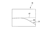
- FIG. 9B is a diagram showing a composite image displayed on the monitor screen 16.
- an image acquired by the camera 57 of the front end camera unit 15, that is, the edge 66 of the upper panel 31 is displayed, and one horizontal target line 67 stored in advance by the storage unit 60 is displayed.
- the camera 41 takes an image. Since it is held in a state of being directed vertically upward through the use hole 22c, an image of the target hole 34 of the upper panel 31 can be reliably acquired until the upper panel 31 and the rear spar 22 come into contact with each other. As a result, the upper panel 31 and the rear spar 22 can be accurately positioned.
- the operator operates the operation panel 138 and drives the lower lifting stand 134 with the lower panel 32 supported by the lower panel support portion 133, thereby lowering the lower side.
- the panel 32 is raised vertically upward.
- the target hole 34 formed in the lower panel 32 is in a state where the axis thereof is inclined with respect to the vertical direction.
- the composite image generated by the composite image generation means 61 is displayed on the monitor screen 16, the operator raises the lower panel 32 while looking at the composite image, and the target of the lower panel 32.
- the hole 34 and the rear spar 22 coincide with each other, the raising of the lower panel 32 is stopped, which is the same as the procedure of the upper panel 31.
- the lower panel 32 is rotated in the horizontal plane with the position fixed on the rear spar 22 as a fulcrum, and when the edge 66 of the lower panel 32 displayed on the monitor screen 16 coincides with the target line 67, the lower panel 32 A point for stopping rotation, a point for fixing the base end of the lower panel 32 and the base end of the rear spar 22 using a fastener, and a tip of the lower panel 32 and a tip of the rear spar 22 using a fastener
- the procedure for the lower panel 32 is the same as that for fixing the.
- the upper panel 31 in order to position the upper panel 31 and the lower panel 32 with respect to the rear spar 22, the upper panel 31 is lowered or the lower panel 32 is raised, but conversely, the rear spar 22 May be raised toward the upper panel 31 or lowered toward the lower panel 32.
- the operator operates the operation panel 138 to lower the upper panel 31 or raise the lower panel 32 while looking at the monitor screen 16.
- control (not shown) is performed.
- the lowering of the upper panel 31 and the raising of the lower panel 32 may be automated. That is, the positional relationship between the target hole 34 and the target line 64 on the monitor screen 16 or the positional relationship between the edge 66 and the target line 67 is detected, and the control unit detects the upper panel suction unit 131 or the lower side based on the detection result. You may make it control operation
- the present invention when manufacturing a structure by assembling a pair of members, it is possible to provide a structure manufacturing method capable of positioning the pair of members with high accuracy by a simple operation.
Landscapes
- Engineering & Computer Science (AREA)
- Mechanical Engineering (AREA)
- Aviation & Aerospace Engineering (AREA)
- Manufacturing & Machinery (AREA)
- Multimedia (AREA)
- Signal Processing (AREA)
- Transportation (AREA)
- Studio Devices (AREA)
- Automatic Assembly (AREA)
Abstract
この構造物製造方法は、上側パネル(31)に形成されたターゲット穴(33)の画像を取得するカメラ(41)をリアスパー(22)に設置する撮像手段設置工程と、カメラ(41)が取得してモニター画面上に表示するターゲット穴(33)の画像を、モニター画面上に予め設定したターゲットラインに位置合わせしながら、上側パネル(31)とリアスパー(22)とを相対移動させることで相対位置を位置決めする位置決め工程と、を含む。
Description
本発明は、一対の部材を組み付けることによって構造物を製造する構造物製造方法及び構造物製造装置に関する。本願は、2010年12月17日に日本に出願された特願2010-282369号について優先権を主張し、その内容をここに援用する。
一対の部材を組み付けることによって構造物を製造する場合、一方の部材と他方の部材とを正確に位置決めする作業が必要となる。この位置決めの方法としては、糸の一端に錘が取り付けられたいわゆる下げ振りを用いる方法が従来用いられてきた。この下げ振りを用いる場合、まず両方の部材の位置を合わせようとする箇所に、位置決め用の穴をそれぞれ形成する。次に、各部材を上下方向に離間させてそれぞれ配置し、上方に位置する部材の穴に下げ振りの糸を挿通させて、錘を鉛直下方に吊り下げた状態とする。そして、この錘を下方に位置する部材の穴の位置に合わせるように保ちながら、一方の部材を他方の部材に向かって下降させる、または他方の部材を一方の部材に向かって上昇させる。そして、一方の部材の穴と他方の部材の穴とを一致させることにより、一対の部材を正確に位置決めすることができる。
この下げ振りを用いた位置決めは、各部材の表面が湾曲面である場合に特に有効な位置決め手段として用いられる。これは、湾曲面に直交して位置決め用の穴をそれぞれ形成すると、一方の部材とその鉛直下方に位置する他方の部材とでは穴の軸線方向が一致せず、一方の部材の穴を通して他方の部材の穴を見ることができない状態だからである。
ところで、構造物の一例としては、航空機の主翼のような航空機構造物が挙げられる。
本出願人は、高い精度で一方の部材を他方の部材に向かって上昇または下降させることが可能な航空機構造物製造装置を従来提唱している(特許文献1を参照)。
本出願人は、高い精度で一方の部材を他方の部材に向かって上昇または下降させることが可能な航空機構造物製造装置を従来提唱している(特許文献1を参照)。
しかし、従来の構造物製造方法によれば、両部材が正確に位置決めされず、位置決め作業のやり直しが発生するという問題があった。より詳細には、下げ振りを用いる場合、一方の部材と他方の部材との間に錘が位置した状態で、いずれかの部材を下降または上昇させる。従って、錘が各部材に干渉するのを防止すべく、両部材が接触する直前に下げ振りを両部材の間から取り除く必要があり、その後は操作者の勘や目測に頼って部材を下降または上昇させることになる。これにより、操作者の技量等によっては両部材の位置決めに誤差が生じる場合があり、この場合、位置決め作業のやり直しが発生する。
本発明は、このような事情を考慮してなされたものであり、その目的は、一対の部材を組み付けて構造物を製造する際に、簡略な作業によって一対の部材を高い精度で位置決めすることが可能な構造物製造方法を提供することにある。
本発明の第一の態様に係る構造物製造方法は、穴がそれぞれ形成された部材同士を、相対移動させて前記穴同士を合わせるようにして組み付けて構造物を製造する構造物製造方法であって、一方の部材に形成された前記穴の画像を取得する撮像手段を他方の部材に設置する撮像手段設置工程と、前記撮像手段が取得してモニター画面上に表示する前記穴の画像を、前記モニター画面上に予め設定したマーキングに位置合わせしながら、部材同士を相対移動させることで部材同士の相対位置を位置決めする位置決め工程と、を含む。
本発明の第一の態様に係る製造方法によれば、撮像手段によって取得されモニター画面上に表示される穴の画像を、モニター画面上のマーキングに位置合わせしながら、部材同士を相対移動させるという簡略な作業により、部材同士を高い精度で位置決めすることができる。また、このような作業は1人の作業者で行うことが可能であるため、人件費の削減によるコストダウンを図ることができる。
また、各部材に形成された穴の軸線が、部材を相対移動させる方向に対して傾斜している場合でも、他方の部材に設置した撮像手段で一方の部材の穴の画像を確実に取得することができる。これにより、部材同士の正確な位置決めが可能となる。
また、各部材に形成された穴の軸線が、部材を相対移動させる方向に対して傾斜している場合でも、他方の部材に設置した撮像手段で一方の部材の穴の画像を確実に取得することができる。これにより、部材同士の正確な位置決めが可能となる。
また、本発明の第二の態様に係る構造物製造方法では、前記撮像手段が、他方の部材に形成された穴を通して一方の部材に形成された前記穴の画像を取得する。
本発明の第二の態様に係る製造方法によれば、位置決め用の穴を用いた簡略な構成により、一方の部材に形成された穴の画像を確実に取得することができる。
また、本発明の第三の態様に係る構造物製造方法では、前記構造物が航空機の翼体であって、前記一方の部材が、前記翼体の外面を形成するパネル部材であり、前記他方の部材が、前記翼体の長手方向に配設される桁部材である。
本発明の第三の態様に係る製造方法によれば、航空機の翼体のような巨大な構造物であっても、1人の作業者による簡略な作業によって、パネル部材と桁部材とを高い精度で位置決めすることができる。
また、本発明の第四の態様に係る構造物製造方法は、前記位置決め工程で前記翼体の基端を位置決めした後に、前記翼体の先端で部材同士の側面の相対位置を位置決めする他の位置決め工程を備える。
本発明の第四の態様に係る製造方法によれば、航空機の翼体のような巨大な構造物であっても、基端側を穴基準で位置合わせした後に、先端側を側面基準で位置合わせすることにより、構造体の全体に渡って、パネル部材と桁部材とを高い精度で位置決めすることができる。
また、本発明の第五の態様に係る構造物製造装置は、穴がそれぞれ形成された部材同士を、相対移動させて前記穴同士を合わせるようにして組み付けて構造物を製造する構造物製造装置であって、一方の部材に取り付けられ、他方の部材に形成された前記穴の画像を取得する撮像手段と、前記穴の画像に対し、予め設定された前記他方の部材を位置合わせすべきマーキング情報を合成することにより合成画像を生成する合成画像生成手段と、前記合成画像を表示する表示手段と、を備える。
本発明の第五の態様に係る構造物製造装置の構成によれば、合成画像生成手段が、撮像手段によって取得される穴の画像に対し、予め設定されたマーキング情報を合成することにより合成画像を生成する。そしてこの合成画像が、表示手段に表示される。これにより、穴の画像をマーキングに位置合わせしながら、部材同士を相対移動させるという簡略な作業により、部材同士を高い精度で位置決めすることができる。また、このような作業は1人の作業者で行うことが可能であるため、人件費の削減によるコストダウンを図ることができる。
また、各部材に形成された穴の軸線が、部材を相対移動させる方向に対して傾斜している場合でも、他方の部材に設置した撮像手段で一方の部材の穴の画像を確実に取得することができる。これにより、部材同士の正確な位置決めが可能となる。
また、各部材に形成された穴の軸線が、部材を相対移動させる方向に対して傾斜している場合でも、他方の部材に設置した撮像手段で一方の部材の穴の画像を確実に取得することができる。これにより、部材同士の正確な位置決めが可能となる。
本発明に係る構造物製造方法によれば、一対の部材を組み付けて構造物を製造する際に、簡略な作業によって一対の部材を高い精度で位置決めすることができる。
以下、図面を参照して本発明の実施の形態について説明する。まず、本発明の実施形態に係る構造物製造方法で製造する構造物について説明する。本実施形態では、構造物として航空機の主翼を製造する場合を例に説明する。
図1は、主翼1の概略構成を示す分解斜視図である。主翼1は、その長手方向に沿って両側部を形成する一対のスパー2(桁部材)と、その上面及び下面を形成する一対のパネル3と、その内部に設けられる複数のリブ4と、を備える。
一対のスパー2は、図1に示すように、主翼1の両側部のうち航空機前方側の側部を形成するフロントスパー21と、航空機後方側の側部を形成するリアスパー22と、を具備している。ここで、図2は、主翼1の基端部すなわち航空機の胴体側の端部を模式的に示した斜視図である。尚、図2ではリブ4の図示を省略している。フロントスパー21及びリアスパー22は、共に断面略U字形状を有する長手部材であって、所定間隔で互いに略平行する一対の平行片22aと、この平行片22aの一端部を接続する接続片22bと、を有している。そして、リアスパー22の基端部には、一対の平行片22aを垂直に貫通して撮影用穴22cがそれぞれ形成されている。
このように構成される一対のスパー2は、それぞれの開口部を互いに向かい合わせるようにして、所定間隔でそれぞれ配置される。
このように構成される一対のスパー2は、それぞれの開口部を互いに向かい合わせるようにして、所定間隔でそれぞれ配置される。
一対のパネル3は、図1に示すように、主翼1の上面を形成する上側パネル31と、下面を構成する下側パネル32と、具備している。上側パネル31及び下側パネル32は、湾曲した断面形状を有するパネル本体3aと、このパネル本体3aの一方の面に長手方向に延びるように設けられた複数本のストリンガー3bと、をそれぞれ有している。
ここで図2に示すように、上側パネル31のパネル本体3aは、平面視で基端側から先端側に向かって徐々に幅が狭くなるような略台形形状を有し、その基端部における前記リアスパー22の撮影用穴22cに対応する位置には、パネル本体3aを垂直に貫通してターゲット穴33が形成されている。また、下側パネル32のパネル本体3aも、上側パネル31のパネル本体3aと平面視で略同形状を有し、その基端部における前記リアスパー22の撮影用穴22cに対応する位置には、パネル本体3aを垂直に貫通してターゲット穴34が形成されている。
一方、ストリンガー3bは、上側パネル31及び下側パネル32の曲げ剛性を高めるためのものであって、図1に示すように、断面略H字形状を有している。
一方、ストリンガー3bは、上側パネル31及び下側パネル32の曲げ剛性を高めるためのものであって、図1に示すように、断面略H字形状を有している。
このように構成される上側パネル31及び下側パネル32は、ストリンガー3bを内側に向けた状態で、一対のスパー2の上方及び下方を覆うようにしてそれぞれ配置される。
ここで、図3は、主翼1の先端部すなわち航空機の胴体と逆側の端部を模式的に示した断面図である。主翼1の先端部では、上側パネル31及び下側パネル32の幅方向両端は、一対のスパー2より所定距離だけ外側へ突出している。
ここで、図3は、主翼1の先端部すなわち航空機の胴体と逆側の端部を模式的に示した断面図である。主翼1の先端部では、上側パネル31及び下側パネル32の幅方向両端は、一対のスパー2より所定距離だけ外側へ突出している。
複数のリブ4は、主翼1を構造的に補強するための部材である。このリブ4は、図1に示すように主翼1の長手方向に所定間隔で設けられ、各リブ4の一端はフロントスパー21に他端はリアスパー22にそれぞれ接続されている。これにより、フロントスパー21とリアスパー22は一定間隔で保持されている。
次に、本発明の実施形態に係る構造物製造方法で使用する構造物製造装置について説明する。ここで本実施形態では、構造物製造装置として、航空機の主翼1を製造する主翼製造装置を例に説明する。図4は、主翼製造装置10の構成を示す概略正面図である。主翼製造装置10は、主翼1を構成するリアスパー22と上側パネル31とを互いに位置決めする第1位置決め装置11と、リアスパー22と下側パネル32とを互いに位置決めする第2位置決め装置12と、主翼1を構成する各種部材を組み立てる組み立て装置13と、を備える。
第1位置決め装置11は、主翼1を構成するリアスパー22の基端部に設置される基端部カメラユニット14と、リアスパー22の先端部に設置される先端部カメラユニット15と、基端部カメラユニット14及び先端部カメラユニット15と配線を介してそれぞれ電気的に接続されるモニター画面16(表示手段)と、を具備している。ここで、図5は、基端部カメラユニット14のリアスパー22への取り付け状態を示す概略断面図である。尚、本実施形態では基端部カメラユニット14及び先端部カメラユニット15を、リアスパー22の基端部及び先端部にそれぞれ設置したが、これに代えてフロントスパー21の基端部及び先端部にそれぞれ設置してもよい。
基端部カメラユニット14は、図5に示すように、リアスパー22に固定されるクランプ部17と、リアスパー22の内側面に対して位置決めされる位置決め部18と、カメラを保持するカメラ保持部19と、を備える。
前記クランプ部17は、図5に示すように、リアスパー22に当接する当接片20と、この当接片20に螺合されたシャフト210と、このシャフト210の一端に設けられた押圧部材220と、シャフト210の他端に設けられた第1操作ノブ23と、当接片20から突出して側方へ延びる突出片24と、を有している。
このように構成されるクランプ部17によれば、第1操作ノブ23を摘んで回転させると、これに伴ってシャフト210が当接片20に対して進退し、押圧部材220と当接片20との間隔が変化する。これにより、この押圧部材220と当接片20との間にリアスパー22の所定箇所を挟持することによってカメラユニットをリアスパー22に取り付けることが可能となっている。
このように構成されるクランプ部17によれば、第1操作ノブ23を摘んで回転させると、これに伴ってシャフト210が当接片20に対して進退し、押圧部材220と当接片20との間隔が変化する。これにより、この押圧部材220と当接片20との間にリアスパー22の所定箇所を挟持することによってカメラユニットをリアスパー22に取り付けることが可能となっている。
前記位置決め部18は、図5に示すように、突出片24に螺合されたボルト25と、このボルト25の軸部に固定して設けられた第2操作ノブ26と、ボルト25の軸部に螺合されたナット27と、このナット27に対しサポートブラケット28を介して固定された基準ブロック29と、を有している。
このように構成される位置決め部18によれば、第2操作ノブ26を回してボルト25を回転させると、これに螺合されたナット27がボルト25の軸部に沿って移動する。これにより、ナット27に固定された基準ブロック29を上下方向に移動させることが可能となっている。
このように構成される位置決め部18によれば、第2操作ノブ26を回してボルト25を回転させると、これに螺合されたナット27がボルト25の軸部に沿って移動する。これにより、ナット27に固定された基準ブロック29を上下方向に移動させることが可能となっている。
基準ブロック29は、図5に示すように、リアスパー22の平行片22aに当接される第1基準面29aと、リアスパー22の接続片22bに当接される第2基準面29bと、第1基準面29aに突出して設けられた凸部29cと、カメラを挿通させるためのカメラ挿通穴29dと、を有している。ここで、第1基準面29a及び第2基準面29bのなす角度は、リアスパー22の平行片22a及び接続片22bのなす角度と略等しく形成されている。また、凸部29cの断面形状は、平行片22aに形成された撮影用穴22cの断面形状に略合致するよう形成されている。
前記カメラ保持部19は、位置決め部18の基準ブロック29に取り付けられるカメラホルダー40と、このカメラホルダー40によって保持されるカメラ41(撮像手段)と、を有している。
カメラホルダー40は、図5に示すように、カメラ41が固定されるカメラ固定穴42と、基準ブロック29に固定するための固定ネジ43と、この固定ネジ43を挟んで両側に突出して設けられた一対の位置決めピン44と、を具備している。このように構成されるカメラホルダー40は、一対の位置決めピン44が基準ブロック29に挿入されることで位置決めされた上で、固定ネジ43が基準ブロック29に螺合されることにより、基準ブロック29の内側面に固定される。
カメラ41は、図5に示すように、断面略円形の細長い形状を有している。このカメラ41は、カメラホルダー40のカメラ固定穴42に挿通固定される。更にカメラ41は、カメラホルダー40の裏側へ突出して基準ブロック29のカメラ挿通穴29d及び凸部29cを挿通されて、リアスパー22の平行片22aに形成された撮影用穴22cの内部に突出することにより、鉛直上方を向いた状態となっている。
ここで、図6は、カメラホルダー40へのカメラ41の取り付けを説明する概略斜視図である。カメラホルダー40にカメラ41を取り付ける際には、カメラ41をカメラ固定穴42の周方向に位置決めした上で、カメラ41を固定する必要がある。そこで、本実施形態では、図6に示すカメラ基準位置確認装置45を用いている。このカメラ基準位置確認装置45は、下台45aと、下台45aから上方へ延びる脚部45bと、脚部45bの上端に下台45aと略平行して設けられた上台45cと、を有している。ここで、上台45cには、カメラ41を挿通可能なカメラ挿通穴45dが貫通形成されるとともに、固定ネジ43を固定するための固定用ネジ穴45eが設けられている。そして、この固定用ネジ穴45eを挟んだ両側には、一対の位置決めピン44を挿入するための一対のピン穴45gがそれぞれ形成されている。また、下台45aには、十字形状の基準ライン45fが表示されており、この基準ライン45fの交点は、カメラ挿通穴45dの中心線から水平方向に所定距離だけ離間している。このような構成によれば、カメラ41が固定されず回転可能な状態で装着されたカメラホルダー40を、カメラ41をカメラ挿通穴45dに挿通させるとともに固定ネジ43を固定用ネジ穴45eに螺合させることにより、上台45cに固定する。そうすると、カメラ41が基準ライン45fの画像を取得し、この画像が不図示のモニター画面に表示される。ここで、このモニター画面上には、基準ライン45fの表示されるべき位置を示すターゲットラインが予め表示されている。従って、カメラ固定穴42及びカメラ挿通穴45dの内部でカメラ41を適宜回転させて、基準ライン45fの画像をターゲットラインに合わせた後、カメラ41の位置を固定すれば、カメラ41を適切な状態でカメラホルダー40に取り付けることができる。
一方、図7は、先端部カメラユニット15のリアスパー22への取り付け状態を示す概略断面図である。先端部カメラユニット15は、リアスパー22に固定されるクランプ部46と、リアスパー22の外側面に対して位置決めされる位置決め部47と、カメラ57を保持するカメラ保持部48と、を備える。
前記クランプ部46は、図7に示すように、リアスパー22を構成する接続片22bの外側面に当接する当接片49と、この当接片49に螺合されたシャフト50と、シャフト50の一端に設けられた押圧部材51と、シャフト50の他端に設けられた第1操作ノブ52と、を有している。このように構成されるクランプ部46によれば、第1操作ノブ52を摘んで回転させると、これに伴ってシャフト50が当接片49に対して進退し、押圧部材51と当接片49との間隔が変化する。これにより、この押圧部材51と当接片49との間にリアスパー22の所定箇所を挟持することによって先端部カメラユニット15をリアスパー22に取り付けることが可能となっている。
前記位置決め部47は、図7に示すように、リアスパー22の接続片22bに沿って進退可能に設けられたL字型の基準ブロック53と、この基準ブロック53から内側へ突出して設けられた位置決め突部54と、を有している。
前記カメラ保持部48は、位置決め部47の基準ブロック53に取り付けられるカメラホルダー56と、このカメラホルダー56に挿通固定されて鉛直上方を向いたカメラ57(撮像手段)と、を有している。尚、カメラホルダー56へのカメラ57の取り付け時には、前述のカメラ基準位置確認装置45を用いる。
図4に示す第2位置決め装置12は、リアスパー22の基端部に設置される基端部カメラユニット58と、リアスパー22の先端部に設置される先端部カメラユニット59と、基端部カメラユニット58及び先端部カメラユニット59と配線を介してそれぞれ電気的に接続されるモニター画面16(表示手段)と、を具備している。尚、これら各部の構成は第1位置決め装置11と同様であるため、ここでは説明を省略する。
図4に示す組み立て装置13は、上側パネル吸着部131と、上側昇降スタンド132と、下側パネル支持部133と、下側昇降スタンド134と、フロントスパー保持部135と、リアスパー保持部136と、搬送部137と、操作盤138と、を備える。
上側パネル吸着部131は、主翼1を構成する上側パネル31を吸着して保持する部材である。また、上側昇降スタンド132は、上側パネル吸着部131に保持された上側パネル31の動作を制御するものであって、より詳細には水平面内における相直交する2軸方向、鉛直方向、及び鉛直軸回りへの回転方向に、上側パネル31を任意に移動させることができる。
下側パネル支持部133は、主翼1を構成する下側パネル32を下方から支持する部材である。また、下側昇降スタンド134は、下側パネル支持部133に支持された下側パネル32の動作を制御するものであって、上側昇降スタンド132と同様に4軸方向に上側パネル31を移動させることができる。
フロントスパー保持部135及びリアスパー保持部136は、主翼1を構成するフロントスパー21及びリアスパー22を、その開口部を相対向させるようにして側方から保持する部材である。これらフロントスパー保持部135及びリアスパー保持部136は、水平方向に進退可能に設けられている。
搬送部137は、図4の紙面に略直交する方向へ走行可能に設けられ、下側パネル32を支持した状態の下側パネル支持部133を搬入しまたは搬出する部材である。
操作盤138は、組み立て装置13の各部の動作を操作するための部材である。この操作盤138の上には、第1位置決め装置11及び第2位置決め装置12を構成するモニター画面16が設置されている。これにより作業者は、モニター画面16を見ながら、操作盤138を操作して組み立て装置13の各部を適宜動作させることができる。
次に、主翼製造装置10の機能構成について説明する。図8は、主翼製造装置10の機能構成を示すブロック図である。主翼製造装置10は、カメラ41及び57(撮像手段)と、記憶手段60と、合成画像生成手段61と、モニター画面16(表示手段)と、を備える。
カメラ41は、上側パネル31及び下側パネル32にそれぞれ形成されたターゲット穴33,34の画像を取得する部材である。また、記憶手段60は、上側パネル31及び下側パネル32を位置合わせすべきターゲットライン情報62(マーキング情報)を予め記憶する部材である。また、合成画像生成手段61は、カメラ41から入力された画像と記憶手段60から入力されたターゲットライン情報62とを合成することにより合成画像を生成する部材である。また、モニター画面16は、合成画像生成手段61が生成した合成画像を表示する部材である。尚、本実施形態では、本発明に係るマーキング情報として線を表示する情報を用いたが、これに限られず点を表示する情報やその他の図形を表示する情報であってもよい。
次に、本発明の実施形態に係る構造物製造方法の工程、及びその作用効果について説明する。
まず作業者は、リアスパー22にカメラ41を設置する撮像手段設置工程を行う。すなわち作業者は、第1位置決め装置11を構成する基端部カメラユニット14をリアスパー22の基端部に、先端部カメラユニット15をリアスパー22の先端部にそれぞれ設置する。より詳細に説明すると、図5に示すように、リアスパー22の内側面に突出して設けられた突片63を、基端部カメラユニット14のクランプ部17で挟持することにより、基端部カメラユニット14をリアスパー22に仮固定する。そして、位置決め部18の第2操作ノブ26を操作して、基準ブロック29を上方へ移動させることにより、その第1基準面29aを平行片22aに、第2基準面29bを接続片22bに対してそれぞれ当接させる。この時、第1基準面29aに突出した凸部29cを、平行片22aに形成された撮影用穴22cに嵌合させる。このように、基端部カメラユニット14をリアスパー22に対して正確に位置決めすることにより、カメラ保持部19に保持されたカメラ41は鉛直上方を向いた状態となる。尚、図に詳細は示さないが、第2基準面29bについては、所定厚みを有する板状のシムが所定の枚数だけ重ねた状態で取り付けることにより、接続片22bに当接するように予め調節している。
また作業者は、図7に示すように、リアスパー22の接続片22bを、先端部カメラユニット15のクランプ部46で挟持し、先端部カメラユニット15をリアスパー22に対して正確に位置決めすることにより、カメラ保持部48に保持されたカメラ57は鉛直上方を向いた状態となる。
尚、第2位置決め装置12を構成する基端部カメラユニット58及び先端部カメラユニット59も、第1位置決め装置11と同様に、リアスパー22の基端部及び先端部にそれぞれ設置する。
次に作業者は、リアスパー22及びフロントスパー21を設置するスパー設置工程を行う。すなわち作業者は、図4に示すように、フロントスパー保持部135によってフロントスパー21を保持するとともに、リアスパー保持部136によってリアスパー22を保持する。そして、フロントスパー保持部135をリアスパー保持部136から遠ざかる方向へ若干後退させた状態で、リアスパー22にリブ4の一端を固定し、フロントスパー保持部135を前進させてリブ4の他端をフロントスパー21に固定する。これにより、リブ4を介してフロントスパー21とリアスパー22とが一体化される。尚、リアスパー22をリアスパー保持部136で保持した状態では、リアスパー22に形成された図5に示す撮影用穴22cは、その軸線が鉛直方向に対して傾斜した状態となっている。
次に作業者は、リアスパー22及びフロントスパー21に対して上側パネル31及び下側パネル32をそれぞれ位置決めする位置決め工程を行う。すなわち作業者は、図4に示すように、上側パネル吸着部131で上側パネル31を保持した状態で、操作盤138を操作して上側昇降スタンド132を駆動することにより、上側パネル31を略鉛直下方に下降させる。尚、上側パネル31を上側パネル吸着部131で吸着した状態では、上側パネル31に形成された図5に示すターゲット穴34は、その軸線が鉛直方向に対して傾斜した状態となっている。
この時、操作盤138の上に設置されたモニター画面16には、前記合成画像生成手段61が生成した合成画像が表示される。ここで、図9Aは、モニター画面16に表示される合成画像を示す図である。モニター画面16には、第1位置決め装置11を構成する基端部カメラユニット14のカメラ41が取得した画像、すなわち上側パネル31に形成されたターゲット穴34の画像が表示されるとともに、記憶手段60が予め記憶した縦方向2本×横方向2本の合計4本のターゲットライン64が表示される。尚、図9Aには、カメラ41が取得したそれ以外の画像、すなわちリアスパー22に形成された撮影用穴22cの開口縁65も表示されている。
作業者は、図9Aに示すように、ターゲット穴34の略円形の画像が、4本のターゲットライン64に内接する状態を保持するようにして、上側パネル31を鉛直下方に徐々に下降させる。尚、ターゲット穴34の画像は、上側パネル31がリアスパー22に近付くに連れて徐々に大きくなる。従って、これに対応してモニター画面16はモード切り替えが可能となっており、縦方向2本のターゲットライン64の間隔、及び横方向2本のターゲットライン64の間隔が、モード切り替えごとにそれぞれ広がる。
そして作業者は、ターゲット穴34の画像と撮影用穴22cの画像とが一致する位置を支点として、上側パネル31を水平面内で回転させることにより、上側パネル31の先端部をリアスパー22の先端部に対して位置決めする。この時、作業者は、モニター画面16の表示を切り替えて、第1位置決め装置11を構成する先端部カメラユニット15のカメラ57が取得した画像を表示させる。ここで、図9Bは、モニター画面16に表示される合成画像を示す図である。モニター画面16には、先端部カメラユニット15のカメラ57が取得した画像、すなわち上側パネル31のエッジ66が表示されるとともに、記憶手段60が予め記憶した横方向1本のターゲットライン67が表示される。
このように、軸線が鉛直方向に対して傾斜した上側パネル31を、同じく軸線が鉛直方向に対して傾斜した撮影用穴22cを有するリアスパー22に対して鉛直方向に組み付ける場合でも、カメラ41が撮影用穴22cを通して鉛直上方を向いた状態で保持されるため、上側パネル31とリアスパー22とが当接するまで、上側パネル31のターゲット穴34の画像を確実に取得することができる。これにより、上側パネル31とリアスパー22との正確な位置決めが可能となる。
そして、作業者は、図9Bに示すように、上側パネル31のエッジ66の画像がターゲットライン67に一致すると、上側パネル31の水平面内での回転を停止させる。これにより、上側パネル31の先端部とリアスパー22の先端部とが互いに位置決めされる。その後、作業者は、上側パネル31とリアスパー22とが当接すると、上側パネル31の下降を停止させる。これにより、ターゲット穴34と撮影用穴22cとが位置合わせされることにより、上側パネル31の基端部とリアスパー22の基端部とが互いに位置決めされる。その後、作業者は、ボルト等の締結具(不図示)を用いることにより、上側パネル31の先端部とリアスパー22の先端部とを固定する。
次に作業者は、図4に示すように、下側パネル支持部133で下側パネル32を支持した状態で、操作盤138を操作して下側昇降スタンド134を駆動することにより、下側パネル32を鉛直上方に上昇させる。尚、下側パネル32を下側パネル支持部133で下方から支持した状態では、下側パネル32に形成されたターゲット穴34は、その軸線が鉛直方向に対して傾斜した状態となっている。
この時、モニター画面16に合成画像生成手段61が生成した合成画像が表示される点、作業者はこの合成画像を見ながら下側パネル32を鉛直上方に上昇させる点、下側パネル32のターゲット穴34とリアスパー22とが一致すると下側パネル32の上昇を停止させる点、については上側パネル31の手順と同様である。
更にその後、リアスパー22に固定した位置を支点として下側パネル32を水平面内で回転させる点、モニター画面16に表示される下側パネル32のエッジ66がターゲットライン67に一致すると下側パネル32の回転を停止させる点、締結具を用いて下側パネル32の基端部とリアスパー22の基端部とを固定する点、締結具を用いて下側パネル32の先端部とリアスパー22の先端部とを固定する点、についても下側パネル32の手順と同様である。
尚、本実施形態では上側パネル31及び下側パネル32をリアスパー22に対して位置決めするために、上側パネル31を下降させまたは下側パネル32を上昇させたが、これとは逆に、リアスパー22を上側パネル31に向かって上昇させ、または下側パネル32に向かって下降させてもよい。
また、本実施形態では、作業者がモニター画面16を見ながら、操作盤138を操作して上側パネル31を下降させまたは下側パネル32を上昇させたが、これに限られず、不図示の制御部による制御の下、上側パネル31の下降や下側パネル32の上昇を自動化してもよい。すなわち、モニター画面16におけるターゲット穴34とターゲットライン64との位置関係、またはエッジ66とターゲットライン67との位置関係を検知し、その検知結果に基づいて制御部が上側パネル吸着部131や下側パネル支持部133等の動作を制御するようにしてもよい。
尚、上述した実施形態において示した各構成部材の諸形状や組み合わせ、或いは動作手順等は一例であって、本発明の主旨から逸脱しない範囲において設計要求等に基づき種々変更可能である。
本発明によれば、一対の部材を組み付けて構造物を製造する際に、簡略な作業によって一対の部材を高い精度で位置決めすることが可能な構造物製造方法を提供できる。
1 主翼
2 スパー
3 パネル
4 リブ
10 主翼製造装置
11 第1位置決め装置
12 第2位置決め装置
13 組み立て装置
14 基端部カメラユニット
15 先端部カメラユニット
16 モニター画面
17 クランプ部
18 位置決め部
19 カメラ保持部
20 当接片
21 フロントスパー
22 リアスパー
23 第1操作ノブ
24 突出片
25 ボルト
26 第2操作ノブ
27 ナット
28 サポートブラケット
29 基準ブロック
31 上側パネル
32 下側パネル
33 ターゲット穴
34 ターゲット穴
40 カメラホルダー
41 カメラ
42 カメラ固定穴
43 固定ネジ
44 位置決めピン
45 カメラ基準位置確認装置
46 クランプ部
47 位置決め部
48 カメラ保持部
49 当接片
50 シャフト
51 押圧部材
52 第1操作ノブ
53 基準ブロック
54 位置決め突部
56 カメラホルダー
57 カメラ
58 基端部カメラユニット
59 先端部カメラユニット
60 記憶手段
61 合成画像生成手段
62 ターゲットライン情報
63 突片
64 ターゲットライン
65 開口縁
66 エッジ
67 ターゲットライン
131 上側パネル吸着部
132 上側昇降スタンド
133 下側パネル支持部
134 下側昇降スタンド
135 フロントスパー保持部
136 リアスパー保持部
137 搬送部
138 操作盤
210 シャフト
220 押圧部材
22a 平行片
22b 接続片
22c 撮影用穴
29a 第1基準面
29b 第2基準面
29c 凸部
29d カメラ挿通穴
3a パネル本体
3b ストリンガー
45a 下台
45b 脚部
45c 上台
45d カメラ挿通穴
45e 固定用ネジ穴
45f 基準ライン
2 スパー
3 パネル
4 リブ
10 主翼製造装置
11 第1位置決め装置
12 第2位置決め装置
13 組み立て装置
14 基端部カメラユニット
15 先端部カメラユニット
16 モニター画面
17 クランプ部
18 位置決め部
19 カメラ保持部
20 当接片
21 フロントスパー
22 リアスパー
23 第1操作ノブ
24 突出片
25 ボルト
26 第2操作ノブ
27 ナット
28 サポートブラケット
29 基準ブロック
31 上側パネル
32 下側パネル
33 ターゲット穴
34 ターゲット穴
40 カメラホルダー
41 カメラ
42 カメラ固定穴
43 固定ネジ
44 位置決めピン
45 カメラ基準位置確認装置
46 クランプ部
47 位置決め部
48 カメラ保持部
49 当接片
50 シャフト
51 押圧部材
52 第1操作ノブ
53 基準ブロック
54 位置決め突部
56 カメラホルダー
57 カメラ
58 基端部カメラユニット
59 先端部カメラユニット
60 記憶手段
61 合成画像生成手段
62 ターゲットライン情報
63 突片
64 ターゲットライン
65 開口縁
66 エッジ
67 ターゲットライン
131 上側パネル吸着部
132 上側昇降スタンド
133 下側パネル支持部
134 下側昇降スタンド
135 フロントスパー保持部
136 リアスパー保持部
137 搬送部
138 操作盤
210 シャフト
220 押圧部材
22a 平行片
22b 接続片
22c 撮影用穴
29a 第1基準面
29b 第2基準面
29c 凸部
29d カメラ挿通穴
3a パネル本体
3b ストリンガー
45a 下台
45b 脚部
45c 上台
45d カメラ挿通穴
45e 固定用ネジ穴
45f 基準ライン
Claims (5)
- 穴がそれぞれ形成された部材同士を、相対移動させて前記穴同士を合わせるようにして組み付けて構造物を製造する構造物製造方法であって、
一方の部材に形成された前記穴の画像を取得する撮像手段を他方の部材に設置する撮像手段設置工程と、
前記撮像手段が取得してモニター画面上に表示する前記穴の画像を、前記モニター画面上に予め設定したマーキングに位置合わせしながら、部材同士を相対移動させることで部材同士の相対位置を位置決めする位置決め工程と、
を含む構造物製造方法。 - 前記撮像手段が、他方の部材に形成された穴を通して一方の部材に形成された前記穴の画像を取得する請求項1に記載の構造物製造方法。
- 前記構造物が航空機の翼体であって、
前記一方の部材が、前記翼体の外面を形成するパネル部材であり、前記他方の部材が、前記翼体の長手方向に配設される桁部材である請求項1または2に記載の構造物製造方法。 - 前記位置決め工程で前記翼体の基端を位置決めした後に、前記翼体の先端で部材同士の側面の相対位置を位置決めする他の位置決め工程を備える請求項3に記載の構造物製造方法。
- 穴がそれぞれ形成された部材同士を、相対移動させて前記穴同士を合わせるようにして組み付けて構造物を製造する構造物製造装置であって、
一方の部材に取り付けられ、他方の部材に形成された前記穴の画像を取得する撮像手段と、
前記穴の画像に対し、予め設定された前記他方の部材を位置合わせすべきマーキング情報を合成することにより合成画像を生成する合成画像生成手段と、
前記合成画像を表示する表示手段と、
を備える構造物製造装置。
Priority Applications (2)
| Application Number | Priority Date | Filing Date | Title |
|---|---|---|---|
| US13/877,488 US9296465B2 (en) | 2010-12-17 | 2011-12-16 | Method for manufacturing a wing body |
| US15/046,196 US9725191B2 (en) | 2010-12-17 | 2016-02-17 | Apparatus for manufacturing a wing body |
Applications Claiming Priority (2)
| Application Number | Priority Date | Filing Date | Title |
|---|---|---|---|
| JP2010-282369 | 2010-12-17 | ||
| JP2010282369A JP5769412B2 (ja) | 2010-12-17 | 2010-12-17 | 構造物製造方法 |
Related Child Applications (2)
| Application Number | Title | Priority Date | Filing Date |
|---|---|---|---|
| US13/877,488 A-371-Of-International US9296465B2 (en) | 2010-12-17 | 2011-12-16 | Method for manufacturing a wing body |
| US15/046,196 Division US9725191B2 (en) | 2010-12-17 | 2016-02-17 | Apparatus for manufacturing a wing body |
Publications (1)
| Publication Number | Publication Date |
|---|---|
| WO2012081700A1 true WO2012081700A1 (ja) | 2012-06-21 |
Family
ID=46244792
Family Applications (1)
| Application Number | Title | Priority Date | Filing Date |
|---|---|---|---|
| PCT/JP2011/079210 Ceased WO2012081700A1 (ja) | 2010-12-17 | 2011-12-16 | 構造物製造方法及び構造物製造装置 |
Country Status (3)
| Country | Link |
|---|---|
| US (2) | US9296465B2 (ja) |
| JP (1) | JP5769412B2 (ja) |
| WO (1) | WO2012081700A1 (ja) |
Cited By (1)
| Publication number | Priority date | Publication date | Assignee | Title |
|---|---|---|---|---|
| WO2018229969A1 (ja) * | 2017-06-16 | 2018-12-20 | 三菱重工業株式会社 | 航空機構造体製造装置 |
Families Citing this family (16)
| Publication number | Priority date | Publication date | Assignee | Title |
|---|---|---|---|---|
| JP5773679B2 (ja) | 2011-02-16 | 2015-09-02 | 三菱重工業株式会社 | 炭素繊維強化プラスチック構造体及びその製造方法 |
| US9943937B2 (en) | 2012-09-28 | 2018-04-17 | The Boeing Company | System and method for manufacturing a wing panel |
| US9925629B2 (en) * | 2013-05-29 | 2018-03-27 | The Boeing Company | Modular and reconfigurable support system |
| ES2755765T3 (es) * | 2013-12-23 | 2020-04-23 | Airbus Operations Sl | Superficie de control de aeronave |
| FR3018267B1 (fr) | 2014-03-07 | 2017-12-22 | Airbus Operations Sas | Dispositif de positionnement relatif de deux pieces telles qu'une traverse et un cadre de fuselage |
| WO2017021722A1 (en) * | 2015-08-05 | 2017-02-09 | Bae Systems Plc | Aircraft part assembly |
| CN105865493A (zh) * | 2016-06-16 | 2016-08-17 | 沈阳飞机工业(集团)有限公司 | 一种用于惯导组件校准的夹具及校准方法 |
| JP6246282B1 (ja) * | 2016-08-01 | 2017-12-13 | 東芝エレベータ株式会社 | パネル加工制御装置及びパネル加工方法 |
| US10179640B2 (en) * | 2016-08-24 | 2019-01-15 | The Boeing Company | Wing and method of manufacturing |
| JP7820126B2 (ja) * | 2020-11-18 | 2026-02-25 | ザ・ボーイング・カンパニー | 組み立てライン製造及び航空機の翼の組み立て |
| JP2022081433A (ja) | 2020-11-18 | 2022-05-31 | ザ・ボーイング・カンパニー | 組み立てライン製造及び航空機の翼の組み立て |
| NL2027418B1 (en) * | 2021-01-26 | 2022-08-26 | Boeing Co | Assembly line fabrication and assembly of aircraft wings |
| EP4001097A1 (en) | 2020-11-18 | 2022-05-25 | The Boeing Company | Assembly line fabrication and assembly of aircraft wings |
| JP7822750B2 (ja) * | 2020-11-18 | 2026-03-03 | ザ・ボーイング・カンパニー | 組み立てライン製造及び航空機の翼の組み立て |
| EP4001098A1 (en) * | 2020-11-18 | 2022-05-25 | The Boeing Company | Assembly line fabrication and assembly of aircraft wings |
| CN114882103B (zh) * | 2022-04-20 | 2024-11-26 | 南昌龙旗信息技术有限公司 | 手写笔螺母对位方法、装置、设备及存储介质 |
Citations (5)
| Publication number | Priority date | Publication date | Assignee | Title |
|---|---|---|---|---|
| JPS6339745A (ja) * | 1986-07-30 | 1988-02-20 | Nissan Motor Co Ltd | 部品組付方法 |
| JPH0523600U (ja) * | 1991-04-30 | 1993-03-26 | 太陽誘電株式会社 | チツプ状部品のマウント装置 |
| JPH09148791A (ja) * | 1995-11-21 | 1997-06-06 | Sony Corp | 部品位置決め装置 |
| JP2003149299A (ja) * | 2001-11-16 | 2003-05-21 | Oht Inc | 位置決め装置及び位置決め方法 |
| JP2010201986A (ja) * | 2009-02-27 | 2010-09-16 | Mitsubishi Heavy Ind Ltd | 航空機構造体製造装置 |
Family Cites Families (9)
| Publication number | Priority date | Publication date | Assignee | Title |
|---|---|---|---|---|
| US6317953B1 (en) * | 1981-05-11 | 2001-11-20 | Lmi-Diffracto | Vision target based assembly |
| JPS59154251A (ja) | 1983-02-22 | 1984-09-03 | 株式会社 東京タツノ | キヤノピイ |
| JPH0523600A (ja) | 1991-07-25 | 1993-02-02 | Iseki & Co Ltd | 穀物乾燥調製システムにおける運転制御装置 |
| JP3143700B2 (ja) | 1995-06-27 | 2001-03-07 | 東京エレクトロン株式会社 | 位置合せ装置 |
| CN1089049C (zh) | 1996-03-22 | 2002-08-14 | 波音公司 | 飞机翼梁,装配飞机翼梁的方法和翼弦定位工具 |
| US6941645B2 (en) | 2000-03-15 | 2005-09-13 | Kazuhiro Kosuge | Automatic piston inserting equipment using a vision system |
| JP2004237535A (ja) | 2003-02-05 | 2004-08-26 | Toray Ind Inc | プリフォームの製造方法および製造装置 |
| US8051547B2 (en) * | 2006-12-29 | 2011-11-08 | The Boeing Company | Robot-deployed assembly tool |
| US9302785B2 (en) * | 2007-11-29 | 2016-04-05 | The Boeing Company | Engine installation using machine vision for alignment |
-
2010
- 2010-12-17 JP JP2010282369A patent/JP5769412B2/ja not_active Expired - Fee Related
-
2011
- 2011-12-16 WO PCT/JP2011/079210 patent/WO2012081700A1/ja not_active Ceased
- 2011-12-16 US US13/877,488 patent/US9296465B2/en active Active
-
2016
- 2016-02-17 US US15/046,196 patent/US9725191B2/en not_active Expired - Fee Related
Patent Citations (5)
| Publication number | Priority date | Publication date | Assignee | Title |
|---|---|---|---|---|
| JPS6339745A (ja) * | 1986-07-30 | 1988-02-20 | Nissan Motor Co Ltd | 部品組付方法 |
| JPH0523600U (ja) * | 1991-04-30 | 1993-03-26 | 太陽誘電株式会社 | チツプ状部品のマウント装置 |
| JPH09148791A (ja) * | 1995-11-21 | 1997-06-06 | Sony Corp | 部品位置決め装置 |
| JP2003149299A (ja) * | 2001-11-16 | 2003-05-21 | Oht Inc | 位置決め装置及び位置決め方法 |
| JP2010201986A (ja) * | 2009-02-27 | 2010-09-16 | Mitsubishi Heavy Ind Ltd | 航空機構造体製造装置 |
Cited By (2)
| Publication number | Priority date | Publication date | Assignee | Title |
|---|---|---|---|---|
| WO2018229969A1 (ja) * | 2017-06-16 | 2018-12-20 | 三菱重工業株式会社 | 航空機構造体製造装置 |
| US11267586B2 (en) | 2017-06-16 | 2022-03-08 | Mitsubishi Heavy Industries, Ltd. | Aircraft structure manufacturing device |
Also Published As
| Publication number | Publication date |
|---|---|
| US20160159499A1 (en) | 2016-06-09 |
| US9296465B2 (en) | 2016-03-29 |
| US20130185918A1 (en) | 2013-07-25 |
| JP2012131239A (ja) | 2012-07-12 |
| US9725191B2 (en) | 2017-08-08 |
| JP5769412B2 (ja) | 2015-08-26 |
Similar Documents
| Publication | Publication Date | Title |
|---|---|---|
| JP5769412B2 (ja) | 構造物製造方法 | |
| US11267586B2 (en) | Aircraft structure manufacturing device | |
| KR101242285B1 (ko) | 홀더 조인트 | |
| US10770857B2 (en) | Electronic equipment assembly method | |
| CN105171374B (zh) | 用于将车辆部件相对于彼此定位的系统和方法 | |
| US10826262B2 (en) | Electronic equipment assembly apparatus and electronic equipment assembly method | |
| US20180368296A1 (en) | Component mounting apparatus | |
| JP5792588B2 (ja) | 電子部品実装装置 | |
| JP6998503B2 (ja) | 電子機器組立装置及び電子機器組立方法 | |
| US20180243909A1 (en) | Electronic device manufacturing apparatus and electronic device manufacturing method | |
| WO2016009744A1 (ja) | 車両整備用リフトのリフトポイント合せ装置 | |
| JP6767625B2 (ja) | 部品搭載装置 | |
| JP6004973B2 (ja) | 電子部品装着装置及び電子部品装着方法 | |
| US10602649B2 (en) | Work head unit, mounting device, and work head unit control method | |
| CN108462020B (zh) | 作业装置 | |
| JP6016940B2 (ja) | 部品実装機 | |
| JP6688971B2 (ja) | 電子機器組立装置および電子機器組立方法 | |
| KR101266714B1 (ko) | 부품 장착 장치의 부품 실장 방법 및 부품 장착 장치 | |
| JP2008171873A (ja) | 位置決め装置、位置決め方法、加工装置及び加工方法 | |
| CN214056834U (zh) | 基板玻璃分离装置以及基板玻璃分离机 | |
| JP5974302B2 (ja) | 電子部品の圧着装置及び電子部品の圧着方法 | |
| JP3606196B2 (ja) | ボール搭載装置およびボール搭載装置における搭載ヘッドの位置調整方法 | |
| JP6603890B2 (ja) | 作業装置および電子機器組立方法 | |
| KR20130137268A (ko) | 이송 및 고정시 플렉시블 디스플레이 판넬의 휨 방지가 가능한 플렉시블 디스플레이 판넬 정렬 및 본딩용 장치 | |
| JP2014210415A (ja) | ヘッドモジュール交換補助具 |
Legal Events
| Date | Code | Title | Description |
|---|---|---|---|
| 121 | Ep: the epo has been informed by wipo that ep was designated in this application |
Ref document number: 11847946 Country of ref document: EP Kind code of ref document: A1 |
|
| WWE | Wipo information: entry into national phase |
Ref document number: 13877488 Country of ref document: US |
|
| NENP | Non-entry into the national phase |
Ref country code: DE |
|
| 122 | Ep: pct application non-entry in european phase |
Ref document number: 11847946 Country of ref document: EP Kind code of ref document: A1 |