WO2012081579A1 - 物品保管装置及び物品移載方法 - Google Patents
物品保管装置及び物品移載方法 Download PDFInfo
- Publication number
- WO2012081579A1 WO2012081579A1 PCT/JP2011/078804 JP2011078804W WO2012081579A1 WO 2012081579 A1 WO2012081579 A1 WO 2012081579A1 JP 2011078804 W JP2011078804 W JP 2011078804W WO 2012081579 A1 WO2012081579 A1 WO 2012081579A1
- Authority
- WO
- WIPO (PCT)
- Prior art keywords
- outrigger
- cage
- locking portion
- rack
- article
- Prior art date
- Legal status (The legal status is an assumption and is not a legal conclusion. Google has not performed a legal analysis and makes no representation as to the accuracy of the status listed.)
- Ceased
Links
Images














Classifications
-
- B—PERFORMING OPERATIONS; TRANSPORTING
- B65—CONVEYING; PACKING; STORING; HANDLING THIN OR FILAMENTARY MATERIAL
- B65G—TRANSPORT OR STORAGE DEVICES, e.g. CONVEYORS FOR LOADING OR TIPPING, SHOP CONVEYOR SYSTEMS OR PNEUMATIC TUBE CONVEYORS
- B65G1/00—Storing articles, individually or in orderly arrangement, in warehouses or magazines
- B65G1/02—Storage devices
- B65G1/04—Storage devices mechanical
- B65G1/0407—Storage devices mechanical using stacker cranes
-
- B—PERFORMING OPERATIONS; TRANSPORTING
- B65—CONVEYING; PACKING; STORING; HANDLING THIN OR FILAMENTARY MATERIAL
- B65G—TRANSPORT OR STORAGE DEVICES, e.g. CONVEYORS FOR LOADING OR TIPPING, SHOP CONVEYOR SYSTEMS OR PNEUMATIC TUBE CONVEYORS
- B65G1/00—Storing articles, individually or in orderly arrangement, in warehouses or magazines
- B65G1/02—Storage devices
- B65G1/04—Storage devices mechanical
- B65G1/0407—Storage devices mechanical using stacker cranes
- B65G1/0414—Storage devices mechanical using stacker cranes provided with satellite cars adapted to travel in storage racks
Definitions
- the present invention relates to an article storage apparatus and an article transfer method that automate the loading and unloading of articles, and more particularly to an article storage apparatus and an article transfer method suitable for storing or transferring heavy objects.
- This application claims priority based on Japanese Patent Application No. 2010-280341 for which it applied to Japan on December 16, 2010, and uses the content here.
- a transfer device described in Patent Document 1 has already been proposed.
- the transfer device described in Patent Document 1 is provided on a lifting table of a stacker crane so that a carriage can be moved via rails, and the carriage is moved to each storage section on a warehouse side by communicating with the rails.
- the rail to obtain is provided, and the support body of the load is provided on the carriage through a plurality of lifting cylinders so as to be lifted and lowered.
- the transfer device has a rack or chain fixed along the side of the carriage, and a plurality of pinion or sprocket wheels to be engaged with the rack or chain at least at the front and rear positions of the carriage and the lift table.
- a driving device is provided on a lifting table of a stacker crane so that a carriage can be moved via rails, and the carriage is moved to each storage section on a warehouse side by communicating with the rails.
- the rail to obtain is provided, and the support body of the load is provided on the carriage through a plurality of lifting cylinders so as to
- positioning pins for accurately positioning the lifting table on the warehouse side are provided at the front, rear, left and right positions of the lifting table so as to be able to appear and retract in the warehouse direction by the cylinder device.
- Such positioning pins position the lift table by engaging with the upper surface of the bottom of the storage unit on the warehouse side.
- Patent Document 1 also describes that an engaging portion for engaging the positioning pin may be separately provided on the storage portion side.
- a transport system having a positioning mechanism for positioning a handling mechanism (transfer device) with respect to a shelf when an article is transferred has been proposed (for example, see Patent Document 2).
- the positioning mechanism described in Patent Document 2 is disposed at the four corners of the frame of the handling mechanism, and can be displaced between a side projecting state and a non-projecting state, and an operation for operating the leg member. Means. When the leg member is in the non-projecting state, the lifting and lowering of the handling mechanism is allowed, and when the leg member is in the projecting state, it can be locked to the rack shelves on both sides.
- the leg member has a triangular cross-section (V-shaped) positioning surface formed with a taper
- the shelf has a concave portion that can be fitted to the positioning surface
- the positioning of the handling mechanism is disclosed in which the positioning surface of the leg member is guided by the concave portion of the shelf.
- positioning is performed between the leg members disposed at the four corners of the frame and the shelves disposed on both sides of the handling mechanism (transfer device). Further, the mounting accuracy of the leg member and the recess is required. In particular, since the shelves themselves are not necessarily arranged so as to face each other, different mounting positions must be individually adjusted for each shelf. Therefore, it may take a great deal of time and labor to arrange the positioning mechanism.
- the present invention was devised in view of the above-described problems, and provides an article storage device and an article transfer method that can easily position a rail and are suitable for storing or transferring heavy objects. With the goal.
- an article storage device includes a hangar having a plurality of racks for storing articles, a crane configured to be movable along the hangar, and suspended up and down on the crane. And a carriage disposed on the cage so as to be able to run between the cage and the rack.
- the cage includes a plurality of outriggers configured to be extendable and retractable toward the rack and to be locked to the rack, and the rack is disposed at a portion where the outrigger is locked.
- a first locking portion, and a second locking portion disposed adjacent to the first locking portion and the extending / contracting direction of the outrigger.
- the second locking portion is configured to be able to position the outrigger.
- One of the outriggers is locked to the second locking portion arranged in a direction in which the carriage travels, and the remaining outriggers are The first locking portion is locked.
- the cage includes a plurality of guide rollers configured to be movable up and down between a plurality of masts constituting the pillar member of the crane, and configured to be able to contact and be separated from the mast. May be spaced apart from the mast when positioning the outrigger to the second locking portion.
- the guide roller is a roller that can roll in contact with the mast, an arm that rotatably supports the roller, and a support member that rotatably supports an end of the arm opposite to the roller.
- Drive means for rotating the arm between a contact position and a separation position of the roller may be included.
- the outrigger may be configured such that a wheel is disposed at a tip and is locked to the first locking portion or the second locking portion by the wheel.
- the second locking portion may have a V-shaped groove capable of positioning the outrigger.
- the first locking portion may be configured such that the outrigger positioned on the second locking portion and the outrigger placed on the first locking portion have the same height.
- the article transfer method includes a hangar having a plurality of racks for storing articles, a crane configured to be movable along the hangar, and capable of moving up and down the crane.
- An article transfer method in an article storage device comprising: a cage suspended on the cage; and a carriage disposed on the cage so as to be able to travel between the cage and the rack.
- the cage includes a plurality of outriggers configured to extend and retract toward the rack and to be locked to the rack, and the rack is a first locking portion disposed at a portion where the outrigger is locked. And a first locking portion and a second locking portion disposed adjacent to the outrigger extending and contracting direction.
- the second locking portion is configured to be able to position the outrigger.
- a cage stop step for stopping the cage at a position above a rack on which the article is to be transferred and an outrigger in the direction in which the carriage is driven is mounted on the second locking portion.
- An outrigger locking step for placing on the rack and locking to the rack; and a carriage moving step for causing the carriage to travel and move to the rack. Transfer between racks.
- the cage includes a plurality of guide rollers configured to be movable up and down between a plurality of masts constituting the pillar member of the crane, and configured to be able to contact and be separated from the mast, and the outrigger extension
- a guide roller retracting step for separating the guide roller from the mast may be provided before or after the step.
- positioning is performed by one of the outriggers extending in the traveling direction of the carriage, and the remaining outriggers are not restrained at the time of positioning.
- the outrigger By positioning the outrigger, the entire cage is positioned relative to the rack. Therefore, the rail of the cage and the rail of the rack can be easily positioned. Therefore, even if the article to be stored is a heavy article, it can be smoothly transferred, and an article storage apparatus and article transfer method suitable for storing or transferring a heavy article can be provided.
- the guide roller can be retracted away from the mast when the cage is positioned. Therefore, when positioning the outrigger, the cage is not restrained by the mast or the guide roller, and the cage can be positioned easily.
- FIG. 1 is a schematic overall configuration diagram of an automatic warehouse including an article storage device according to a first embodiment of the present invention. It is a top view of the article storage apparatus shown in FIG. It is a side view which shows the contact state of the guide roller shown in FIG. It is a front view which shows the contact state of the guide roller shown in FIG.
- FIG. 3 is a side view showing a retracted state of the guide roller shown in FIG. 2.
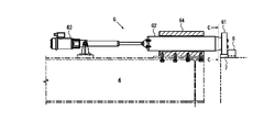
- FIG. 3 is a partial cross-sectional side view illustrating a state in which the outrigger illustrated in FIG. 2 is contracted.
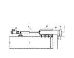
- FIG. 3 is a partial cross-sectional side view showing a state in which the outrigger shown in FIG. 2 is extended to a first locking portion.
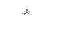
- FIG. 4C is a cross-sectional view taken along the line CC in FIG. 4B. It is a partial cross section side view which shows the state which the outrigger shown in FIG. 2 extended to the 2nd latching
- FIG. 1 is a schematic overall configuration diagram of an automatic warehouse including an article storage device according to a first embodiment of the present invention.
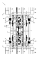
- FIG. 2 is a plan view of the article storage device shown in FIG. 3A is a side view showing a contact state of the guide roller shown in FIG.
- FIG. 3B is a front view showing a contact state of the guide roller shown in FIG. 2.
- 3C is a side view showing a retracted state of the guide roller shown in FIG. 4A is a partial cross-sectional side view illustrating a state in which the outrigger illustrated in FIG. 2 is contracted.
- FIG. 1 is a schematic overall configuration diagram of an automatic warehouse including an article storage device according to a first embodiment of the present invention.
- FIG. 2 is a plan view of the article storage device shown in FIG. 3A is a side view showing a contact state of the guide roller shown in FIG.
- FIG. 3B is a front view showing a contact state of the guide roller shown in FIG. 2.
- 3C is a side view
- FIG. 4B is a partial cross-sectional side view showing a state in which the outrigger shown in FIG. 2 is extended to the first locking portion.
- 4C is a cross-sectional view taken along the line CC in FIG. 4B.
- FIG. 4D is a partial cross-sectional side view showing a state where the outrigger shown in FIG. 2 extends to the second locking portion.
- 4E is a view on arrow E in FIG. 4D.
- the article storage device 1 is configured to have a hangar 2 having a plurality of racks 21 for storing articles A, and to be movable along the hangar 2.
- a crane 3 suspended from the crane 3 so as to be movable up and down, and a carriage 5 disposed on the cage 4 so as to be able to travel between the cage 4 and the rack 21.
- the cage 4 includes a plurality of outriggers 6 configured to be extendable and contractable toward the rack 21 and to be locked to the rack 21.
- the rack 21 includes a first locking portion 7 disposed at a portion where the outrigger 6 is locked, and a second locking portion 8 disposed adjacent to the first locking portion 7 and the expansion / contraction direction of the outrigger 6.
- the second locking portion 8 is configured so that the outrigger 6 can be positioned.
- One of the outriggers 6 is locked to the second locking portion 8 arranged in the direction in which the carriage 5 travels, and the remaining outrigger 6 Is locked to the first locking portion 7.
- the article storage apparatus 1 is applied to a so-called automatic warehouse.
- the article A is a mold that is a heavy article of about 5 to 10 tons or more (for example, about 40 to 50 tons).
- the mold removed by the press machine is transported to the loading / unloading port 22 of the article storage apparatus 1 by a mold exchanging device, a transport cart, a crane, and the like, and is transferred to the cart 5.
- the carriage 5 loaded with the article A is transported to the front of the desired rack 21 by the movement of the crane 3 and the cage 4, deposits the article A in the rack 21, and stores the article A.
- the empty carriage 5 is transported to the front of the rack 21 where the desired mold (article A) is stored, and the article A is transferred to the carriage 5. It is transferred to the loading / unloading port 22 and transferred to a die changer, a transfer carriage, a crane, etc., and a desired die is supplied to the press machine.
- the article A is not limited to a mold, and may be other heavy objects such as a steel material, a steel plate, various parts, and various products.
- the hangar 2 has, for example, racks 21 arranged in a multi-stage high layer as shown in FIGS. 1 and 2.
- the hangar 2 is configured by arranging a plurality of such multi-stage high-rise racks 21 in parallel along the traveling direction of the crane 3.
- the hangar 2 is a frame structure constituted by a plurality of support columns 23 and a plurality of side frames 24, for example.
- the rack 21 includes rails 25 that are arranged on the frame structure and support the carriage 5 so that the carriage 5 can travel, and support members 26 that can support both sides of the pallet P on which the article A is placed.
- Such racks 21 are arranged on both sides of the crane 3, and are often configured so that the article A can be transferred to both racks 21 with one crane 3.
- a rail 27 is laid on the portion of the crane 3 between the racks 21 where the crane 3 travels.
- the configurations of the hangar 2 and the rack 21 are merely examples, and are not limited to those illustrated, and various structures that have been used in the past can be used.
- the hangar 2 does not need to be configured in a multi-stage high layer, and may be configured in a single stage or a low layer.
- the crane 3 includes, for example, a traveling unit 31 that can travel on the rail 27, a mast 32 that is erected at four corners of the traveling unit 31, a lifting drive source 33 that is disposed above the mast 32, and a lifting drive source 33.
- the cage 4 is connected to the other end of the chain 34.
- the cage 4 is suspended by a chain 34 of the crane 3 so as to be lifted and lowered.
- the cage 4 is a frame structure composed of a plurality of frames, for example.
- the cage 4 includes a plurality of guide rollers 41 configured to be movable up and down between a plurality of masts 32 constituting a pillar member of the crane 3 and configured to be able to contact and be separated from the mast 32. ing.
- the plurality of guide rollers 41 are disposed between the plurality of masts 32 and can come into contact with the inner surfaces of the plurality of masts 32.
- the guide roller 41 includes a roller 41a that can roll while contacting the mast 32, an arm 41b that rotatably supports the roller 41a, and an arm 41b opposite to the roller 41a.
- a support member 41c that rotatably supports the end portion, and a drive unit 41d that rotates the arm 41b between a contact position and a separation position of the roller 41a with respect to the mast 32 are provided.
- the support member 41 c is configured by a pair of plate members erected on the cage 4.
- the arm 41b is composed of a pair of plate members that are pin-coupled to the support member 41c.
- a roller 41a is pin-coupled to the tip of the arm 41b. With this configuration, the roller 41a is rotatably supported by the arm 41b, and the arm 41b is rotatably supported by the support member 41c.
- the drive means 41d is, for example, an actuator that is swingably supported by a support frame 41e that is erected on the cage 4.
- an actuator such as a hydraulic cylinder, a pneumatic cylinder, and an electric cylinder can be arbitrarily selected and used as the driving unit 41d.
- the tip of the drive means 41d is connected to the arm 41b via a pin-coupled fixing member. Therefore, as shown in FIGS. 3A and 3C, the arm 41b can be rotated by extending and contracting the actuator, and the position of the roller 41a is separated from the contact position shown in FIG. 3A and the separation (retraction) shown in FIG. 3C. ) Can be changed to position.
- the driving means 41d above the arm 41b and the like, the limited plane of the cage 4 can be used effectively, and the position of the roller 41a can be changed with a small installation area. Further, when the roller 41a is brought into contact with the mast 32, the roller 41a can be pushed in from above even if there is no sufficient gap between the mast 32 and the roller 41a, and the position of the cage 4 is adjusted. However, the roller 41a can be reliably arranged at the contact position.
- the configuration of the guide roller 41 is not limited to the illustrated one.
- the roller 41a is disposed rotatably at the tip of the driving unit 41d, and the driving unit 41d can be expanded and contracted in a direction perpendicular to the mast 32.
- the roller 41a may be changed in the horizontal direction between the contact position and the separation (retraction) position by expanding and contracting the driving means 41d.
- the cage 4 has a pair of outriggers 6 that are arranged so as to extend and contract toward the opposite rack 21.
- the racks 21 are arranged on both sides of the cage 4, two pairs (four) of outriggers 6 are arranged on the cage 4.
- the outrigger 6 has a wheel 61 disposed at the tip, and is configured to be locked to the first locking portion 7 or the second locking portion 8 by the wheel 61. ing.
- the outrigger 6 includes a wheel 61, a support member 62 that rotatably supports the wheel 61, a drive unit 63 that slides the support member 62, a guide member 64 that guides the slide of the support member 62,
- the support member 62 is, for example, a prismatic or cylindrical steel material.
- the guide member 64 is a cylinder member which can insert the support member 62, for example.
- the drive means 63 is an actuator such as a hydraulic cylinder, a pneumatic cylinder, and an electric cylinder disposed on the cage 4, for example.
- the wheel 61 is provided on the support member 62 so as to be rotatable about an axis extending in the expansion / contraction direction of the outrigger 6.
- the first locking portion 7 and the second locking portion 8 are disposed on the upper surface of the rack 21.
- the first locking portion 7 and the second locking portion 8 are disposed at positions facing each outrigger 6 in a state where the guide roller 41 is in contact with the mast 32.
- the first locking portion 7 is a flat plate member whose upper surface is formed substantially flat, and is disposed so as to correspond to all the outriggers 6. That is, two first locking portions 7 are provided in each rack 21 and are arranged corresponding to the pair of outriggers 6 in the cage 4.
- the upper surface of the first locking portion 7 is formed to be substantially flat so as to allow the movement of the wheel 61 of the outrigger 6 in the horizontal direction (movement in the horizontal direction perpendicular to the expansion / contraction direction of the outrigger 6).
- the first locking portion 7 can lock the wheel 61 of the outrigger 6 in the vertical direction (the movement of the wheel 61 downward can be regulated), and the outrigger 6 can be positioned in the vertical direction. It has become.
- the second locking portion 8 is a flat plate member having a V-shaped groove capable of positioning the wheel 61 of the outrigger 6, and is provided at one location of the rack 21. It arrange
- the wheel 61 of the outrigger 6 is placed from above in the V-shaped groove of the second locking portion 8, thereby moving the wheel 61 in the horizontal direction (moving in the horizontal direction orthogonal to the expansion and contraction direction of the outrigger 6. ) And the downward movement in the vertical direction are both restricted.
- the second locking portion 8 can lock the wheel 61 in the horizontal direction and the vertical direction, and can position the outrigger 6 in the horizontal direction and the vertical direction.
- the V-shaped groove of the second locking portion 8 only needs to have a shape that can restrain the movement of the wheel 61.
- the V-shaped groove may be a U-shaped groove or a rectangular groove.
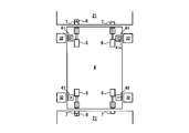
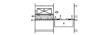
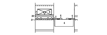
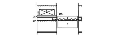
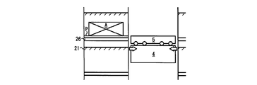
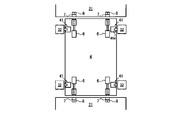
- FIG. 5A is a diagram showing a cage stop process in the cage positioning process.
- FIG. 5B is a diagram illustrating a guide roller retracting step in the cage positioning step.
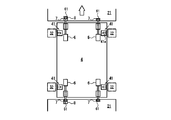
- FIG. 5C is a diagram illustrating an outrigger extension process in the cage positioning process.
- FIG. 5D is a diagram illustrating an outrigger extension step in the cage positioning step.
- bogie 5 is abbreviate
- the outrigger 6 is set so that the wheel 61 is placed on the second locking portion 8 arranged in the rack 21 in the arrow direction. Stretch. About the remaining three outriggers 6, the outriggers 6 are extended so that the wheels 61 are placed on the first locking portions 7 of the racks 21 on both sides. Thereafter, the outrigger 6 is locked to the rack 21 by lowering the cage 4.
- FIGS. 4B and 4C show a state where the wheel 61 of the outrigger 6 is placed on the first locking portion 7.
- 4D and 4E show a state in which the wheel 61 of the outrigger 6 is placed on the second locking portion 8.
- the first locking portion 7 is arranged so that the outrigger 6 positioned on the second locking portion 8 and the outrigger 6 placed on the first locking portion 7 have the same height.
- the height h is set.
- the cage 4 By the vertical positioning by the first locking portion 7 and the second locking portion 8 of the outrigger 6, the cage 4 is positioned in the vertical direction with respect to the rack 21, and the rail of the cage 4 and the rail 25 of the rack 21 are aligned. Properly positioned in the vertical direction. Further, since the movement of the wheel 61 placed on the first locking portion 7 in the horizontal position is not restricted, the cage 4 is mounted on the rack 21 by the horizontal positioning of the one outrigger 6 by the second locking portion 8. The rails of the cage 4 and the rails 25 of the rack 21 are appropriately positioned in the horizontal direction. The rails of the cage 4 are appropriately positioned with respect to the rails 25 of the rack 21 by the functions of the first locking portion 7 and the second locking portion 8. Further, since the guide roller 41 is separated from the mast 32 when positioning the outrigger 6 to the second locking portion 8, the movement of the cage 4 is restrained by the mast 32 when positioning the cage 4. And can be positioned freely.
- the outrigger 6 is extended so that the wheel 61 is placed on the second locking portion 8 disposed in the rack 21 in the arrow direction.
- the outriggers 6 are extended so that the wheels 61 are placed on the first locking portions 7 of the racks 21 on both sides.
- the outrigger 6 is locked to the rack 21 by lowering the cage 4.
- the positioning of the rail 25 of the rack 21 and the rail of the cage 4 can be accurately performed by locking the outrigger 6 to the second locking portion 8 arranged in the direction in which the carriage 5 is desired to travel. it can. That is, it is possible to prevent the occurrence of displacement in these rails.
- the carriage 5 is placed on a rail (indicated by a one-dot chain line in the figure) arranged on the cage 4. Similar to the cage 4, the carriage 5 is a frame structure configured by a plurality of frames, for example.
- the carriage 5 has a plurality of wheels 51, and some of the wheels 51 are configured to be able to run on the rails by the driving means 52.
- the wheel 51 placed on one rail of the pair of rails may have an annular protrusion or groove guided by a groove or protrusion formed on the rail (in the present embodiment, A protrusion or a groove is formed on the left wheel 51).
- the lifting / lowering means 53 includes, for example, a lifting / lowering base 53a that can be extended and contracted in a substantially vertical direction, and a driving means 53b that moves the lifting / lowering base 53a up and down.
- a hydraulic unit is illustrated as the driving means 53b.
- the driving means 53b may be an electric type, and the elevating means 53 may be a pantograph type.
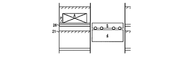
- FIG. 6 A is a figure which shows a cage stop process among the loading processes by the goods transfer method which concerns on 1st embodiment of this invention.
- FIG. 6B is a diagram showing a lift-up process in the load placing process.
- FIG. 6C is a diagram illustrating an outrigger extension step in the load placing step.
- FIG. 6D is a diagram illustrating an outrigger locking step in the load placing step.
- FIG. 6E is a diagram showing a cart moving process in the same loading process.
- FIG. 6F is a diagram illustrating a lift-down process in the load placing process.
- FIG. 6G is a diagram showing a cart pullback process in the same loading process.
- FIG. 6 A is a figure which shows a cage stop process among the loading processes by the goods transfer method which concerns on 1st embodiment of this invention.
- FIG. 6B is a diagram showing a lift-up process in the load placing process.
- FIG. 6C is a diagram illustrating an outrigger extension step in
- FIG. 6H is a diagram illustrating an outrigger contraction process in the same loading process.
- FIG. 7: A is a figure which shows a cage stop process among the loading processes by the goods transfer method which concerns on 1st embodiment of this invention.
- FIG. 7B is a diagram illustrating an outrigger extension process in the same cargo pickup process.
- FIG. 7C is a diagram illustrating an outrigger locking step in the same loading process.
- FIG. 7D is a diagram showing a cart moving process in the same loading process.
- FIG. 7E is a diagram showing a lift-up process in the load taking process.
- FIG. 7F is a diagram showing a cart pulling back step in the same loading process.
- FIG. 7G is a diagram showing a lift-down process in the same loading process.
- FIG. 7H is a diagram showing an outrigger contraction step in the same load pickup step.
- the article storage device 1 illustrated in FIGS. 6A to 6H and FIGS. 7A to 7H includes a hangar 2 having a plurality of racks 21 for storing the articles A, and a crane configured to be movable along the hangar 2 as described above. 3, a cage 4 suspended from the crane 3 so as to be movable up and down, and a carriage 5 disposed on the cage 4 so as to be able to travel between the cage 4 and the rack 21.
- the cage 4 includes a plurality of outriggers 6 configured to be extendable and contractable toward the rack 21 and to be locked to the rack 21.
- the rack 21 includes a first locking portion 7 disposed at a portion where the outrigger 6 is locked, and a second locking portion 8 disposed adjacent to the first locking portion 7 and the expansion / contraction direction of the outrigger 6.
- locking part 8 is comprised so that the outrigger 6 can be positioned.
- the article transfer method stops the cage 4 at a position above the rack 21 to which the article A is to be transferred.
- Outrigger extension in which one of the outriggers 6 in the direction in which the carriage 5 travels is placed on the second locking portion 8 and the outrigger 6 is extended so that the remaining outrigger 6 is placed on the first locking portion 7.
- a step a step of lowering the cage 4 to place the outrigger 6 on the first locking portion 7 and the second locking portion 8 and locking the outrigger 6 to the rack 21; And a carriage moving step for moving the article A between the cage 4 and the rack 21 by the movement of the carriage 5.
- the loading process is a process of storing the article A in a predetermined rack 21, and the loading process is a process of taking out the article A stored in the rack 21 and supplying it to the outside.
- the loading process by the article transfer method includes a cage stopping process illustrated in FIG. 6A, a lift-up process illustrated in FIG. 6B, an outrigger extending process illustrated in FIG. 6C, and FIG.
- the cage stopping process shown in FIG. 6A is a process of stopping the cage 4 in front of the desired rack 21.
- the stop position of the cage 4 is set at a position higher than the rack 21 to which the article A is to be transferred so that it does not interfere with the rack 21 when the outrigger 6 is extended.
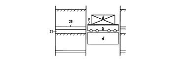
- the lift-up process shown in FIG. 6B is a process in which the pallet P on which the article A on the carriage 5 is placed is lifted by the lifting means 53 (see FIG. 2).
- the pallet P is lifted up so as to be arranged at a position above the support member 26 of the rack 21.
- the cage 4 is run with the pallet P lifted up in advance, it is in the state after the lift-up process shown in FIG. 6B at the stage of the cage stop process shown in FIG. 6A.
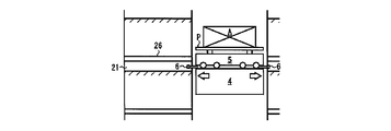
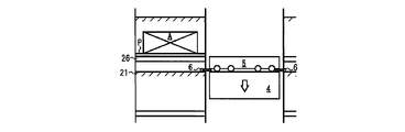
- the outrigger extension step shown in FIG. 6C is a step of extending the outrigger 6 to a position where it can be locked to the rack 21. Specifically, the outrigger 6 is extended so that one of the outriggers 6 in the direction in which the carriage 5 travels is placed on the second locking portion 8 and the remaining outrigger 6 is placed on the first locking portion 7. (See FIG. 5C or 5D).
- the cage 4 includes a plurality of guide rollers 41 configured to be movable up and down between the plurality of masts 32 constituting the pillar member of the crane 3 and configured to be able to contact and be separated from the mast 32.
- the outrigger locking step shown in FIG. 6D is a step of locking the outrigger 6 to the rack 21. Specifically, the cage 4 is lowered and the outrigger 6 is placed on the first locking portion 7 and the second locking portion 8 and locked to the rack 21. At this time, the outrigger 6 is locked to the second locking portion 8 disposed on the rack 21 in the direction in which the carriage 5 is desired to travel. The remaining outrigger 6 is locked to the first locking portion 7.
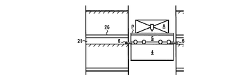
- the cart moving process shown in FIG. 6E is a process of moving the cart 5 from the cage 4 to the rack 21.
- the rails of the cage 4 and the rails 25 of the rack 21 can be accurately positioned, and the carriage 5 can run smoothly.
- the rail is accurately positioned, so that problems such as the inability to travel of the carriage 5 and the failure of the apparatus can be suppressed.
- the lift-down process shown in FIG. 6F is a process of lowering the pallet P on which the article A on the carriage 5 is placed. Specifically, the pallet P is lifted down so as to be transferred from the carriage 5 to the support member 26 of the rack 21. Through this process, the article A is transferred from the cart 5 to the rack 21 together with the pallet P.
- 6G is a step of pulling the empty cart 5 back onto the cage 4. Also in this case, since the rails of the cage 4 and the rails 25 of the rack 21 are accurately positioned, the carriage 5 can run smoothly.
- the outrigger contraction process shown in FIG. 6H is a process in which the outrigger 6 is contracted to release the cage 4 from the rack 21. Specifically, by raising the cage 4 to the stop position of the cage 4 shown in FIG. 6C, the outrigger 6 is separated from the first locking portion 7 and the second locking portion 8, and then shown in FIG. 6H. As described above, the outrigger 6 is contracted and retracted. In this way, by slightly raising the outrigger 6 before retracting it, it is possible to suppress the catch of the outrigger 6, minimize the load on the outrigger 6, and prevent failure and the like. In the outrigger contraction process at the time of loading, since the carriage 5 is empty, the weight is light. Therefore, the lifting process of the cage 4 is omitted, and the outrigger 6 is contracted and retracted as it is. May be.
- the loading process by the article transfer method includes a cage stopping process shown in FIG. 7A, an outrigger extending process shown in FIG. 7B, an outrigger locking process shown in FIG. 7C, and FIG.
- the cage stop process shown in FIG. 7A is a process of stopping the cage 4 in front of the rack 21 in which the article A to be taken out is stored.
- the stop position of the cage 4 is set at a position above the target rack 21 so as not to interfere with the rack 21 when the outrigger 6 is extended.
- the 7B is a process of extending the outrigger 6 to a position where it can be locked to the rack 21. Specifically, the outrigger 6 is extended so that one of the outriggers 6 in the direction in which the carriage 5 travels is placed on the second locking portion 8 and the remaining outrigger 6 is placed on the first locking portion 7. (See FIG. 5C or 5D).
- the cage 4 includes a plurality of guide rollers 41 configured to be movable up and down between the plurality of masts 32 constituting the pillar member of the crane 3 and configured to be able to contact and be separated from the mast 32.
- the outrigger locking step shown in FIG. 7C is a step of locking the outrigger 6 to the rack 21. Specifically, the cage 4 is lowered and the outrigger 6 is placed on the first locking portion 7 and the second locking portion 8 and locked to the rack 21. At this time, the outrigger 6 is locked to the second locking portion 8 disposed on the rack 21 in the direction in which the carriage 5 is desired to travel. The remaining outrigger 6 is locked to the first locking portion 7.
- 7D is a process of moving the carriage 5 from the cage 4 to the rack 21.
- the carriage movement process shown in FIG. As described above, by locking the outrigger 6 to the rack 21, the rails of the cage 4 and the rails 25 of the rack 21 can be accurately positioned, and the carriage 5 can run smoothly.
- FIG. 7E is a process of lifting the pallet P placed on the support member 26 of the rack 21 together with the article A.
- the lift-up process shown in FIG. Specifically, the pallet P on which the article A is placed is lifted by the lifting / lowering means 53 (see FIG. 2) of the carriage 5 moved on the rack 21, and the pallet P and the article A are lifted up from the rack 21. Through this process, the article A can be transferred from the rack 21 to the carriage 5.
- the lift-down process shown in FIG. 7G is a process of lowering the pallet P on which the article A on the carriage 5 is placed. Specifically, the pallet P is lifted down so as to be placed on the entire top surface of the carriage 5. Through this process, the article A is transferred from the rack 21 together with the pallet P to the carriage 5. In addition, when it is necessary to lift up the pallet P at the transport destination (for example, the entrance / exit 22 and the other rack 21) of the article A after unloading, the lift-down process is omitted, and the pallet P is removed. You may make it move to the next process, without lifting down.
- the transport destination for example, the entrance / exit 22 and the other rack 21
- the outrigger contraction process shown in FIG. 7H is a process in which the outrigger 6 is contracted to release the cage 4 from the rack 21. Specifically, by raising the cage 4 to the stop position of the cage 4 shown in FIG. 7B, the outrigger 6 is separated from the first locking portion 7 and the second locking portion 8, and then shown in FIG. 7H. As described above, the outrigger 6 is contracted and retracted. In this way, by slightly raising the cage 4 before retracting the outrigger 6, the catch of the outrigger 6 can be suppressed, the load on the outrigger 6 can be minimized, and failure or the like can be prevented. it can. In particular, during loading, since the heavy article A is placed, the load on the outrigger 6 is high. Therefore, it is preferable that the outrigger 6 is retracted after the cage 4 is lifted.
- positioning is performed by one of the outriggers 6 extending in the traveling direction of the carriage 5, and the remaining outriggers 6 are not restrained during positioning. Therefore, the entire cage 4 is positioned by positioning one outrigger 6, and the rail of the cage 4 and the rail 25 of the rack 21 can be easily positioned. Therefore, even if the article A to be stored is a heavy article, the article A can be smoothly transferred, and an article storage apparatus 1 and an article transfer method suitable for storing or transferring a heavy article can be provided. .
- the guide roller 41 When the cage 4 has the guide roller 41 that contacts the mast 32, the guide roller 41 is retracted so as to be separated from the mast 32 when the cage 4 is positioned. For this reason, the cage 4 is not restrained by the mast 32 or the guide roller 41 when the outrigger 6 is positioned, and the cage 4 can be positioned easily.
- FIG. 8A is a plan view showing an article storage device according to a second embodiment of the present invention.
- FIG. 8B is a plan view showing the article storage device according to the third embodiment of the present invention.
- FIG. 8C is a plan view showing the article storage device according to the fourth embodiment of the present invention.
- FIG. 8D is a plan view showing an article storage device according to a fifth embodiment of the present invention.
- the illustration of the carriage 5 is omitted.
- symbol is attached
- FIGS. 8A to 8D the arrangement of the first locking portion 7 and the second locking portion 8 is changed.
- the second locking portion 8 is arranged on a diagonal line while the arrangement of the first locking portion 7 of the first embodiment is left as it is.
- the third embodiment shown in FIG. 8B the positions of the first locking portion 7 and the second locking portion 8 adjacent to each other in the first embodiment are exchanged. Even in these arrangements, the cage 4 can be accurately positioned by the outrigger 6 as in the first embodiment.
- the second locking portions 8 are arranged at positions adjacent to all the first locking portions 7. In this way, by configuring the locking portions on the side of all the racks 21 by a combination of the first locking portion 7 and the second locking portion 8, any outrigger 6 on the side on which the carriage 5 travels can be arbitrarily selected. One selected outrigger 6 can be locked to the second locking portion 8. Therefore, the load applied to the outrigger 6 can be made equal by, for example, alternately replacing the outrigger 6 to be restrained by the second locking portion 8, and the consumption and failure of some outriggers 6 can be suppressed. it can.
- the wheel 51 placed on one rail 42 of the pair of rails 42 of the cage 4 is guided by the groove 42 a (or protrusion) formed on the rail 42.
- the rail 25 having the groove 25a or the protrusion is provided.
- the second locking portion 8 is adjacent to the first locking portion 7 on the side away from the right side (right side in the figure). According to this configuration, since the position where the outrigger 6 is locked to the second locking portion 8 and the position where the wheel 51 is locked are separated, the positioning accuracy of the carriage 5 is slightly lower than that of the first embodiment. However, the effect is substantially the same as in the first embodiment.
- the wheel 51 placed on one rail 42 of the pair of rails 42 of the cage 4 has a groove 42 a (or a protrusion) formed on the rail 42.
- a similar groove 25a (or protrusion) is formed on the rail 25 on the rack 21 side corresponding to the rail 42, and the groove 25a and the protrusion are provided.
- the second locking portion 8 is adjacent to the first locking portion 7 on the side close to the rail 25 (left side in the figure). According to such a configuration, the position where the outrigger 6 is locked to the second locking portion 8 and the position where the wheel 51 is locked are close to each other.
- the same groove 25a and the rail 25 of the rack 21 having the projection can be accurately positioned, and the carriage 5 including the wheel 51 having the annular projection and the groove can be smoothly run.
- the present invention can be used for an article storage apparatus and an article transfer method for loading and unloading articles.
Landscapes
- Engineering & Computer Science (AREA)
- Mechanical Engineering (AREA)
- Warehouses Or Storage Devices (AREA)
Abstract
Description
本願は、2010年12月16日に日本に出願された特願2010-280341号に基づき優先権を主張し、その内容をここに援用する。
さらに、ガイドローラ41は、アウトリガー6を第二係止部8に位置決めする際に、マスト32から離間されていることから、ケージ4の位置決め時において、マスト32によりケージ4の移動が拘束されることがなく、自由に位置決めすることができる。
2 格納庫
3 クレーン
4 ケージ
5 台車
6 アウトリガー
7 第一係止部
8 第二係止部
21 ラック
32 マスト
41 ガイドローラ
41a ローラ
41b アーム
41c 支持部材
41d 駆動手段
61 車輪
Claims (8)
- 物品を格納する複数のラックを有する格納庫と、該格納庫に沿って移動可能に構成されたクレーンと、該クレーンに昇降可能に吊下されたケージと、該ケージと前記ラックとの間を走行可能に前記ケージ上に配置された台車と、を有する物品保管装置において、
前記ケージは、前記ラックに向かって伸縮可能かつ前記ラックに係止可能に構成された複数のアウトリガーを有し、
前記ラックは、前記アウトリガーが係止される部分に配置された第一係止部と、該第一係止部と前記アウトリガーの伸縮方向に隣接して配置された第二係止部と、を有し、該第二係止部は、前記アウトリガーを位置決め可能に構成されており、前記台車を走行させる方向に配置された前記第二係止部に前記アウトリガーの一つを係止させ、残りのアウトリガーを前記第一係止部に係止させるようにした物品保管装置。 - 前記ケージは、前記クレーンの柱部材を構成する複数のマストの間で昇降可能に構成されるとともに、前記マストに当接可能かつ離間可能に構成された複数のガイドローラを有し、該ガイドローラは、前記アウトリガーを前記第二係止部に位置決めする際に、前記マストから離間されている請求項1に記載の物品保管装置。
- 前記ガイドローラは、前記マストに当接して転動可能なローラと、該ローラを回転可能に支持するアームと、該アームの前記ローラと反対側の端部を回動可能に支持する支持部材と、前記アームを前記ローラの当接位置と離間位置との間で回動させる駆動手段と、を有する請求項2に記載の物品保管装置。
- 前記アウトリガーは、先端に車輪が配置されており、該車輪により前記第一係止部又は前記第二係止部に係止されるように構成されている請求項1に記載の物品保管装置。
- 前記第二係止部は、前記アウトリガーを位置決め可能なV字状溝を有する請求項1に記載の物品保管装置。
- 前記第一係止部は、前記第二係止部に位置決めされた前記アウトリガーと前記第一係止部に載置された前記アウトリガーとが同じ高さとなるように構成されている請求項1に記載の物品保管装置。
- 物品を格納する複数のラックを有する格納庫と、該格納庫に沿って移動可能に構成されたクレーンと、該クレーンに昇降可能に吊下されたケージと、該ケージと前記ラックとの間を走行可能に前記ケージ上に配置された台車と、を有する物品保管装置における物品移載方法であって、
前記ケージは、前記ラックに向かって伸縮可能かつ前記ラックに係止可能に構成された複数のアウトリガーを有し、
前記ラックは、前記アウトリガーが係止される部分に配置された第一係止部と、該第一係止部と前記アウトリガーの伸縮方向に隣接して配置された第二係止部と、を有し、該第二係止部は、前記アウトリガーを位置決め可能に構成されており、
前記物品を移載したいラックよりも上方の位置で前記ケージを停止させるケージ停止工程と、
前記台車を走行させる方向のアウトリガーの一つを前記第二係止部に載置させるとともに残りのアウトリガーを前記第一係止部に載置させるように前記アウトリガーを延伸させるアウトリガー延伸工程と、
前記ケージを降下させて前記アウトリガーを前記第一係止部及び前記第二係止部に載置して前記ラックに係止させるアウトリガー係止工程と、
前記台車を走行させて前記ラックに移動させる台車移動工程と、を有し、
前記台車の移動によって前記物品を前記ケージと前記ラックとの間で移載する物品移載方法。 - 前記ケージは、前記クレーンの柱部材を構成する複数のマストの間で昇降可能に構成されるとともに、前記マストに当接可能かつ離間可能に構成された複数のガイドローラを有し、前記アウトリガー延伸工程の前又は後に、前記ガイドローラを前記マストから離間させるガイドローラ退避工程を有する請求項7に記載の物品移載方法。
Priority Applications (3)
| Application Number | Priority Date | Filing Date | Title |
|---|---|---|---|
| US13/988,874 US9415933B2 (en) | 2010-12-16 | 2011-12-13 | Article storage device and article transfer method |
| CA2819636A CA2819636C (en) | 2010-12-16 | 2011-12-13 | Article storage device and article transfer method |
| MX2013006269A MX339676B (es) | 2010-12-16 | 2011-12-13 | Dispositivo para almacenamiento de articulos y metodo para transferencia de articulos. |
Applications Claiming Priority (2)
| Application Number | Priority Date | Filing Date | Title |
|---|---|---|---|
| JP2010280341A JP5838549B2 (ja) | 2010-12-16 | 2010-12-16 | 物品保管装置及び物品移載方法 |
| JP2010-280341 | 2010-12-16 |
Publications (1)
| Publication Number | Publication Date |
|---|---|
| WO2012081579A1 true WO2012081579A1 (ja) | 2012-06-21 |
Family
ID=46244678
Family Applications (1)
| Application Number | Title | Priority Date | Filing Date |
|---|---|---|---|
| PCT/JP2011/078804 Ceased WO2012081579A1 (ja) | 2010-12-16 | 2011-12-13 | 物品保管装置及び物品移載方法 |
Country Status (5)
| Country | Link |
|---|---|
| US (1) | US9415933B2 (ja) |
| JP (1) | JP5838549B2 (ja) |
| CA (1) | CA2819636C (ja) |
| MX (1) | MX339676B (ja) |
| WO (1) | WO2012081579A1 (ja) |
Families Citing this family (3)
| Publication number | Priority date | Publication date | Assignee | Title |
|---|---|---|---|---|
| DE102016201962B4 (de) * | 2016-02-10 | 2025-04-24 | Bundesdruckerei Gmbh | Verfahren und Vorrichtung zur Förderung eines Regallager-Transportfahrzeugs |
| JP7075768B2 (ja) * | 2018-02-05 | 2022-05-26 | 住友重機械搬送システム株式会社 | 自動倉庫システム |
| WO2021209649A1 (es) | 2020-04-14 | 2021-10-21 | Imaz Arce Guillermo Pedro | Sistema automatico de almacenamiento y recuperacion de troqueles |
Citations (3)
| Publication number | Priority date | Publication date | Assignee | Title |
|---|---|---|---|---|
| JPS6324106U (ja) * | 1986-07-30 | 1988-02-17 | ||
| JPS63277106A (ja) * | 1987-05-08 | 1988-11-15 | Nkk Corp | 立体収納庫における昇降台の位置決め装置 |
| JPH0378325B2 (ja) * | 1984-04-26 | 1991-12-13 | Nippon Kokan Kk |
Family Cites Families (6)
| Publication number | Priority date | Publication date | Assignee | Title |
|---|---|---|---|---|
| JPS6324106A (ja) | 1987-07-09 | 1988-02-01 | Tokyo Optical Co Ltd | フレ−ム形状測定装置 |
| JPH0378325A (ja) | 1989-08-21 | 1991-04-03 | Matsushita Electric Ind Co Ltd | 信号検出装置 |
| JPH06321316A (ja) | 1993-03-19 | 1994-11-22 | Yamaha Motor Co Ltd | 搬送システム |
| FI108346B (fi) * | 1998-07-07 | 2002-01-15 | Sunds Defibrator Panelhandling | Laitteisto levynippujen kõsittelemiseksi |
| US6113336A (en) * | 1999-10-05 | 2000-09-05 | Chang; Tien-Sheng | Warehousing system having a conveying device for transferring articles between two levels of a multistory building |
| EP1638866B1 (de) * | 2003-06-30 | 2006-10-11 | Tgw-Transportgeräte Gmbh | Verfahren und vorrichtung zur manipulation von ladehilfsmitteln |
-
2010
- 2010-12-16 JP JP2010280341A patent/JP5838549B2/ja active Active
-
2011
- 2011-12-13 CA CA2819636A patent/CA2819636C/en active Active
- 2011-12-13 WO PCT/JP2011/078804 patent/WO2012081579A1/ja not_active Ceased
- 2011-12-13 MX MX2013006269A patent/MX339676B/es active IP Right Grant
- 2011-12-13 US US13/988,874 patent/US9415933B2/en active Active
Patent Citations (3)
| Publication number | Priority date | Publication date | Assignee | Title |
|---|---|---|---|---|
| JPH0378325B2 (ja) * | 1984-04-26 | 1991-12-13 | Nippon Kokan Kk | |
| JPS6324106U (ja) * | 1986-07-30 | 1988-02-17 | ||
| JPS63277106A (ja) * | 1987-05-08 | 1988-11-15 | Nkk Corp | 立体収納庫における昇降台の位置決め装置 |
Also Published As
| Publication number | Publication date |
|---|---|
| US9415933B2 (en) | 2016-08-16 |
| JP5838549B2 (ja) | 2016-01-06 |
| MX2013006269A (es) | 2013-12-02 |
| CA2819636A1 (en) | 2012-06-21 |
| JP2012126526A (ja) | 2012-07-05 |
| US20130243551A1 (en) | 2013-09-19 |
| CA2819636C (en) | 2016-01-19 |
| MX339676B (es) | 2016-06-03 |
Similar Documents
| Publication | Publication Date | Title |
|---|---|---|
| US7575407B2 (en) | Article storage facility | |
| JP5834558B2 (ja) | 自動倉庫、自動倉庫の可搬情報提示方法 | |
| JP2017509561A (ja) | 高層ラック倉庫におけるコンテナの積付け及び取降ろし又は積替え方法及び装置 | |
| TW201637967A (zh) | 自動倉庫 | |
| TW201940396A (zh) | 倉儲系統 | |
| TWI491543B (zh) | 物品移載裝置及具有該裝置之堆高式起重機 | |
| US20230192425A1 (en) | Apparatus and method for unloading and loading a transport unit | |
| JP5838549B2 (ja) | 物品保管装置及び物品移載方法 | |
| US20240017920A1 (en) | Dynamic storage system and methods thereof | |
| JP5966588B2 (ja) | カゴ台車用移載装置 | |
| JP7331445B2 (ja) | スタッカクレーン | |
| US4194864A (en) | Three-dimensional automatic warehouse equipment | |
| JP6593270B2 (ja) | 物品搬送設備 | |
| US12466646B2 (en) | Article storage facility | |
| JP2016020260A (ja) | 搬送車 | |
| JPH09156714A (ja) | 自動倉庫 | |
| JP5821823B2 (ja) | 物品収納設備 | |
| JP3595644B2 (ja) | 物品格納装置 | |
| JPH10218311A (ja) | 自動倉庫 | |
| JP2015009952A (ja) | 自動倉庫及びその運転方法 | |
| JP6006100B2 (ja) | 機械式駐車装置 | |
| JP3912785B2 (ja) | 立体自動倉庫の入出庫装置 | |
| JPS63272704A (ja) | 立体収納庫 | |
| JP6671981B2 (ja) | 自動倉庫システム | |
| JPH03177205A (ja) | トンネルセグメントの一時保管・搬入設備 |
Legal Events
| Date | Code | Title | Description |
|---|---|---|---|
| 121 | Ep: the epo has been informed by wipo that ep was designated in this application |
Ref document number: 11848017 Country of ref document: EP Kind code of ref document: A1 |
|
| WWE | Wipo information: entry into national phase |
Ref document number: 13988874 Country of ref document: US |
|
| ENP | Entry into the national phase |
Ref document number: 2819636 Country of ref document: CA |
|
| WWE | Wipo information: entry into national phase |
Ref document number: MX/A/2013/006269 Country of ref document: MX |
|
| NENP | Non-entry into the national phase |
Ref country code: DE |
|
| 122 | Ep: pct application non-entry in european phase |
Ref document number: 11848017 Country of ref document: EP Kind code of ref document: A1 |