WO2012074045A1 - エアゾール噴射装置 - Google Patents
エアゾール噴射装置 Download PDFInfo
- Publication number
- WO2012074045A1 WO2012074045A1 PCT/JP2011/077788 JP2011077788W WO2012074045A1 WO 2012074045 A1 WO2012074045 A1 WO 2012074045A1 JP 2011077788 W JP2011077788 W JP 2011077788W WO 2012074045 A1 WO2012074045 A1 WO 2012074045A1
- Authority
- WO
- WIPO (PCT)
- Prior art keywords
- injection
- liquid
- flow path
- aerosol
- sound
- Prior art date
- Legal status (The legal status is an assumption and is not a legal conclusion. Google has not performed a legal analysis and makes no representation as to the accuracy of the status listed.)
- Ceased
Links
Images


Classifications
-
- B—PERFORMING OPERATIONS; TRANSPORTING
- B65—CONVEYING; PACKING; STORING; HANDLING THIN OR FILAMENTARY MATERIAL
- B65D—CONTAINERS FOR STORAGE OR TRANSPORT OF ARTICLES OR MATERIALS, e.g. BAGS, BARRELS, BOTTLES, BOXES, CANS, CARTONS, CRATES, DRUMS, JARS, TANKS, HOPPERS, FORWARDING CONTAINERS; ACCESSORIES, CLOSURES, OR FITTINGS THEREFOR; PACKAGING ELEMENTS; PACKAGES
- B65D83/00—Containers or packages with special means for dispensing contents
- B65D83/14—Containers for dispensing liquid or semi-liquid contents by internal gaseous pressure, i.e. aerosol containers comprising propellant
- B65D83/28—Nozzles, nozzle fittings or accessories specially adapted therefor
-
- B—PERFORMING OPERATIONS; TRANSPORTING
- B05—SPRAYING OR ATOMISING IN GENERAL; APPLYING FLUENT MATERIALS TO SURFACES, IN GENERAL
- B05B—SPRAYING APPARATUS; ATOMISING APPARATUS; NOZZLES
- B05B1/00—Nozzles, spray heads or other outlets, with or without auxiliary devices such as valves, heating means
- B05B1/002—Nozzles, spray heads or other outlets, with or without auxiliary devices such as valves, heating means designed to reduce the generation or the transmission of noise or to produce a particular sound; associated with noise monitoring means
-
- B—PERFORMING OPERATIONS; TRANSPORTING
- B05—SPRAYING OR ATOMISING IN GENERAL; APPLYING FLUENT MATERIALS TO SURFACES, IN GENERAL
- B05B—SPRAYING APPARATUS; ATOMISING APPARATUS; NOZZLES
- B05B1/00—Nozzles, spray heads or other outlets, with or without auxiliary devices such as valves, heating means
- B05B1/34—Nozzles, spray heads or other outlets, with or without auxiliary devices such as valves, heating means designed to influence the nature of flow of the liquid or other fluent material, e.g. to produce swirl
-
- B—PERFORMING OPERATIONS; TRANSPORTING
- B05—SPRAYING OR ATOMISING IN GENERAL; APPLYING FLUENT MATERIALS TO SURFACES, IN GENERAL
- B05B—SPRAYING APPARATUS; ATOMISING APPARATUS; NOZZLES
- B05B15/00—Details of spraying plant or spraying apparatus not otherwise provided for; Accessories
Definitions
- the present invention relates to an aerosol injection device.
- Patent Document 1 There is a product that provides comfort by cooling articles covering the body such as clothing and shoes (Patent Document 1).
- the shoe swell improvement spray of Patent Document 1 sprays a liquid that lowers the temperature by vaporization heat on the inside of the shoe. Thereby, when this liquid is sprayed on the inside of the shoe, the temperature in the shoe can be instantaneously lowered, and the shoe stuffiness is improved.
- a cooling sensation material such as menthol or lactate menthyl is used rather than injecting the liquid described in Patent Document 1 onto the injection target. It is thought that it is more effective to spray the contained liquid onto the object to be ejected, but these cooling sensations give a burning sensation or irritation to the skin when the concentration exceeds a certain level, so there is an upper limit to the concentration that can be used. is there. Accordingly, in order to maximize the cooling effect felt by humans, it is necessary to set the concentration of the cooling sensation material to a maximum usable concentration. However, in recent years, a higher cooling effect is desired by consumers.
- the concentration of the cooling sensation material cannot be increased any more, so a factor different from the adjustment of the concentration of the cooling sensation material is added to enhance the cooling effect actually felt by consumers, or psychological cooling. It is necessary to make the effect feel high, that is, to increase the “cooling effect”.
- An object of the present invention is to solve these problems of the prior art, and to provide an aerosol injection device that is easy to inject with a simple configuration and can obtain a higher “cooling effect”.
- the present invention provides an aerosol injection apparatus for injecting a liquid containing a propellant enclosed therein via an injection flow path, and a background of 35 dB is provided at an injection port of the injection flow path.
- the present invention provides an aerosol injection device including a fine particle generation unit that makes the injection sound at that time 90 dB or more and injects a liquid in a mist form.
- the injection port includes the fine particle generation unit, and the fine particle generation unit has a function of setting the injection sound when the background is 35 dB to 90 dB or more and the liquid in a mist shape. It has the function to inject. That is, at the injection port, an explosion occurs when the liquid propellant constituting a part of the liquid is instantly vaporized. By this explosion, the liquid is turned into particles and becomes a mist, and the vibration of the mist resonates in the injection flow path to generate an injection sound.
- the fine particle generation unit sets the ejection sound generated at this time to 90 dB or more when the background is 35 dB.
- the fine particle generation unit can eject the liquid as a mist
- the mist form is a general term for fine liquid particles, which means a state in which the liquid is evaporated and condensed, and a state in which the injected liquid can be visually recognized as white smoke.
- the injection sound can be set to 90 dB or more by the fine particle generation unit, and a psychologically high cooling effect feeling can be obtained due to the influence of the sound, and the injection area can be widened and the liquid can be used. The effect is easily obtained.
- the fine particle generating section is preferably configured by setting the inner diameter of the injection flow path to 1.0 mm to 2.0 mm, and further, the inner diameter of the injection flow path is set to 1.2 mm to 1.8 mm. More preferred.
- the fine particle generation unit has such a configuration, the propellant is effectively vaporized at the injection port, and the liquid can be injected in a mist-like manner, and a sufficient space in which the injection sound generated by the explosion resonates is sufficient. And the injection sound can be effectively 90 dB or more.
- the fine particle generation unit can be configured only by setting the inner diameter size of the injection flow path within the above-described range, the configuration can be simplified and injection can be easily performed.
- the injection flow path is a straight type.
- the straight type means that the injection port and the injection flow path are linearly connected.
- the said structure WHEREIN The said liquid can be injected with respect to the inner side of shoes.
- a relatively hard material is used for shoes, and a closed space is formed.
- the sound generated from the ejection port reflects and resonates in the closed space formed on the inner side of the shoe, effectively generating a sound of 90 dB or more.
- the mist-like liquid can be blown back inside the shoe to enlarge the spray area.
- the propellant is preferably liquefied petroleum gas or dimethyl ether.
- Liquefied petroleum gas (LPG) or dimethyl ether (DME) is instantly vaporized by contact with air, and can effectively generate an explosion. Thereby, the injection sound can be set to 90 dB or more, and the effect of making the liquid mist can be easily obtained.
- FIG. 1st embodiment of an aerosol injection device It is a fragmentary sectional view showing a 1st embodiment of an aerosol injection device concerning the present invention. It is sectional drawing of the modification of the injection button of the aerosol injection apparatus shown in FIG. It is sectional drawing of the injection button which shows 2nd Embodiment of the aerosol injection apparatus which concerns on this invention. It is an injection button which shows 3rd Embodiment of the aerosol injection apparatus which concerns on this invention, (a) is sectional drawing, (b) is a front view of a microparticle generation
- This aerosol ejecting apparatus ejects liquid onto a body wearing tool as an ejected object.
- the liquid is composed of a liquid agent to be ejected onto an object to be ejected and a liquid propellant.
- the liquid agent is a mixture of a solvent such as ethanol and a refreshing agent such as menthol or menthol lactate.
- the body wearing device has a cooling effect for a predetermined time.
- the propellant liquefied petroleum gas (LPG) or dimethyl ether (DME) is preferably used.
- liquefied petroleum gas is used.
- the aerosol injection device includes an aerosol container 2 that stores a liquid and an injection button 1.
- the injection button 1 has a so-called straight-type injection flow path, forms an upper surface, and has a corrugated pressing portion 3 to be a pressing portion of the injection button 1 and an upper end of the aerosol container 2 provided on the inner diameter side.
- a stem connection portion 4 that is externally fitted to a stem 5 of a protruding valve mechanism (not shown), an outer peripheral wall 14 that forms an outer peripheral surface, and an injection nozzle 15 that has a liquid injection port 11 are provided.
- the injection nozzle 15 has a tapered portion and a cylindrical portion whose outer diameter side is reduced in diameter toward the opposite outer peripheral wall side, and the cylindrical portion is fitted in the horizontal hole 10 that opens in the outer peripheral wall.
- a hole portion is formed which has a constant inner diameter D and forms a linear injection flow path. The tip of the injection nozzle 15 protrudes from the outer peripheral wall 14 to the outer peripheral side.
- the injection button 1 is provided with a first injection flow path 6 that is continuous with a hole 13 formed on the inner diameter side of the stem connection portion 4 and extends in the axial direction (vertical direction) of the stem 5. And a second injection flow path 7 extending in a direction (horizontal direction) substantially orthogonal to the first injection flow path 6 is provided.
- the second injection channel 7 has a constant inner diameter D and is circular in cross section.
- the valve mechanism is opened by pressing the pressing portion 3 and pushing down the stem 5 to the aerosol container 2 side via the stem connecting portion 4, and the liquid in the aerosol container 2 is introduced into the injection button 1. .
- the liquid introduced from the stem 5 into the first injection flow path 6 is introduced into the second injection flow path 7, can flow through the second injection flow path 7, and can be injected from the tip thereof.
- the tip of the second ejection flow path 7 becomes the ejection port 11 that ejects the liquid.
- the injection port 11 refers to, for example, a region indicated by a range A in FIG. That is, the ejection port 11 in the present invention refers not only to the distal end edge of the second ejection flow path 7 but also the distal end region including the distal end edge.
- the injection port 11 of the second injection flow path 7 includes a fine particle generation unit 12.
- the fine particle generation unit 12 has both a function of making the injection sound 90 dB or more when the background is 35 dB and a function of ejecting the liquid in a mist form. That is, an explosion occurs when the liquid propellant that constitutes a part of the liquid is instantaneously vaporized at the injection port 11. By this explosion, the liquid is turned into particles and becomes a mist, and the vibration of the mist resonates in the injection flow path to generate an injection sound.
- the fine particle generation unit 12 sets the ejection sound generated at this time to 90 dB or more when the background is 35 dB.
- the spray area can be wide.
- the mist form is a general term for fine liquid particles, which means a state in which the liquid is evaporated and condensed, and a state in which the injected liquid can be visually recognized as white smoke.
- the fine liquid particles to be ejected in the aerosol ejecting apparatus of the present invention are those having a particle size of, for example, 10 ⁇ m to 50 ⁇ m.
- the fine particle generation unit 12 has an inner diameter D (a diameter when the cross section of the injection flow path is circular, a short axis when the cross section of the injection flow path is circular) of 1.0 mm to 2.0 mm. More preferably, the thickness is 1.2 mm to 1.8 mm. In the present embodiment, the fine particle generation unit 12 is configured with the inner diameter D of the second injection flow path 7 being 1.2 mm.
- the fine particle generation unit 12 has such a configuration, the propellant is effectively vaporized at the injection port 11 and the liquid can be injected in the form of a mist, and the space in which the injection sound generated by the explosion resonates. Can be sufficiently secured, and the injection sound can be effectively 90 dB or more.
- the fine particle generation unit 12 can be configured only by setting the inner diameter size of the second injection flow path 7 within the above-described range, the configuration can be simplified and injection can be easily performed.
- the inner diameter D is smaller than 1.0 mm (usually the inner diameter size is 0.5 mm to 0.7 mm), a sufficient resonance space cannot be secured and the injection sound becomes smaller than 90 dB. Further, liquid is clogged in the ejection flow path 7 and vaporization is hindered, and generation of fine particles is not promoted, making it difficult to eject in the form of a mist, resulting in a narrow ejection area.
- the inner diameter D exceeds 2.0 mm, the resonance space becomes too wide and resonance is not promoted, and the injection sound becomes smaller than 90 dB.
- the liquid propellant comes into contact with air at the injection port 11, the pressure drop is insufficient and vaporization is hindered. It becomes.
- the liquid ejection amount is preferably 1.5 g to 3.0 g per second, and more preferably 2.0 g to 2.5 g. Is more preferable.
- the liquid in the present embodiment has a cooling effect for a predetermined time by being sprayed on an article covering the body.
- the injection sound can be 90 dB or more, and a psychologically high cooling effect can be obtained due to the influence of the sound.
- the spray area can be widened, and the cooling effect by the liquid can be easily obtained. In this way, the user can obtain a high cooling effect feeling by adding a cooling effect feeling felt from the jetting sound at the time of liquid jetting to the actual cooling effect felt from the liquid component.
- the article covering the body is used as a shoe and the liquid is ejected to the inside of the shoe, a higher cooling effect can be obtained.
- a relatively hard material is used for shoes, and a closed space is formed.
- the sound generated from the ejection port 11 reflects and resonates in the closed space formed on the inside of the shoe, effectively generating a sound of 90 dB or more. be able to.
- the mist-like liquid can be blown back inside the shoe to enlarge the spray area.
- FIG. 2 shows a modification of the aerosol injection device of the first embodiment.
- the aerosol injection device in FIG. 2 is different from the aerosol injection device according to the first embodiment in the form of the injection port.
- this aerosol spray device is one in which the spray nozzle 15 is omitted and has a mounting body 16 attached to the horizontal hole 10.
- the mounting body 16 includes a flange portion 18 and a cylindrical portion 20, and the mounting body 16 is mounted by fitting the cylindrical portion 20 into the horizontal hole 10.
- An axial hole 26 is formed on the inner diameter surfaces of the flange 18 and the cylindrical part 20, and this axial hole 26 becomes the second injection flow path 7.
- the injection port 11 refers to a region indicated by a range A in FIG.
- the injection port 11 is located on the inner diameter side of the outer peripheral wall 14.
- the injection port 11 includes a fine particle generation unit 12.
- the fine particle generation unit 12 is provided at the tip of the second injection flow path 7. That is, the fine particle generation unit 12 is configured by setting the inner diameter of the axial hole portion 26 to, for example, 1.8 mm.
- FIG. 3 shows an aerosol injection device according to a second embodiment of the present invention. This aerosol injection device is different from the aerosol injection device according to the first embodiment in the form of the second injection flow path 17 and the fine particle generation unit 22.
- the 2nd injection channel 17 of a 2nd embodiment extends in the direction (horizontal direction) substantially orthogonal to injection channel 6, and the tip is an opening shape.
- the second injection flow path 17 has a constant inner diameter (for example, 0.9 mm), a first part 20 that forms a linear flow path, and a smaller diameter (for example, 0.8 mm) than the first part 20. It has the 2nd part 24 which comprises a linear flow path, and the 3rd part 25 which expands from the front-end
- the aerosol injection device also includes the fine particle generation unit 22 at the injection port 21 (for example, the range A in FIG. 3) of the second injection flow path 17.
- the fine particle generation unit 22 includes the second part 24 and the third part 25 of the second injection flow path 17. That is, the pressure of the liquid introduced into the second injection flow path 17 is increased in the second part 24, and the amount of the propellant coming into contact with the air in the third part 25 can be increased. For this reason, vaporization can be accelerated
- resonance can be promoted by the third portion 25, and the fluid can be diffused in all directions, and sprayed in the form of a mist to increase the spray area.
- FIG. 4 shows an aerosol injection device according to a third embodiment of the present invention. This aerosol injection device is different from the aerosol injection device according to the first embodiment in the form of the second injection flow path 27 and the fine particle generation unit 32.
- the second injection flow path 27 of the third embodiment has a constant inner diameter and is a linear flow path.
- the inner diameter of the second injection flow path 27 is, for example, 2.1 mm.
- the aerosol injection device also includes a fine particle generation unit 32 at the injection port 31 of the second injection flow path 27.
- the fine particle generation unit 32 is configured by a film member that is stretched around the distal end edge of the second injection flow path 27.
- the film member has a large number of holes 40 formed throughout. Thereby, when the liquid introduced into the ejection port 31 is ejected, the liquid passes through the hole 40 and becomes fine particles, and is ejected in the form of a mist, so that the ejection area can be enlarged.
- the injection sound generated by the explosion at the injection port 31 is resonated by the film member, so that the injection sound can be 90 dB or more.
- Samples A to I are manufactured as aerosol injection devices. Samples A to G have straight type injection flow paths, and the inner diameters of the injection ports are 0.7 mm, 1.0 mm, and 1 as shown in FIG. 2 mm, 1.6 mm, 1.8 mm, 2.4 mm, and 2.6 mm. Samples H and I have a so-called mechanical breakup type injection channel, and the inner diameter of the injection channel is 0.5 mm and 0.6 mm. Samples B, C, D and E are examples, and samples A and F to I are comparative examples.
- the configuration other than the injection button is common to all samples.
- the liquid ejected by the ejection device is 100 ml with a ratio of the liquid agent (Table 1) to be ejected to the ejected object and the liquid propellant (liquefied petroleum gas (LPG)) being 3: 7.
- the tin can was filled.
- a stem hole (not shown) that opens when the spray button is pressed down has a hole diameter of 0.6 mm ⁇ 1, and the amount of liquid sprayed per second is 2.0 to 2.5 g.
- Samples A to F, H, and I the injection sound when injecting toward the inside of the shoe and the injection sound when injecting without an injection object were measured.
- sample G only the injection sound was measured when it was injected toward the inside of the shoe.
- a microphone of a sound level meter (manufactured by Sansho Co., Ltd .: Model STM-102) was set on the shoe mouth, and each injection device was arranged so that the distance between the injection port and the microphone was about 10 cm.
- the liquid was jetted for 2 seconds inside the shoe, and the maximum value of the jetting sound was measured.
- the liquid was ejected for 2 seconds so that the distance between the ejection port and the microphone was about 10 cm, and the maximum value of the ejection sound was measured.
- the background volume was measured under a condition of 35 dB or less.
- FIG. 6 shows the result of measuring each sample 6 times and averaging them.
- “without hatching” indicates a case of spraying toward the inside of the shoe, and “with hatching” indicates a case of spraying without an injection target.
- the sample D (inner diameter 1.6 mm) is the peak and the inner diameter is the same regardless of whether it is injected toward the inside of the shoe or there is no injection target.
- the inner side of the shoe than the injection sound injected without the injection target object It can be seen that the injection sound injected toward is loud.
- the samples B, C, D, and E have an injection sound of 90 dB or more. This is considered to be because the sound generated from the injection port reflects and resonates in the closed space formed on the inner side of the shoe.
- sample B inner diameter 1.0 mm
- the injection sound in the state where there is no injection target is 74.7 dB
- the injection sound injected into the shoe reaches 95.5 dB.
- the injection sound in a state where there is no injection target is 72.5 dB, and the injection sound injected into the shoe reaches 95.9 dB. That is, it was found that in the aerosol injection device configured as in the present invention, in order to effectively obtain an injection sound of 90 dB or more, it is particularly effective to inject inside the shoe.
- an aerosol spray device for samples A to G a device for rotating a roll to a site to be coated and applying a liquid directly to the site to be coated (hereinafter referred to as a roll), and a device for spraying a liquid in a mist form using a pump mechanism
- a roll a device for rotating a roll to a site to be coated and applying a liquid directly to the site to be coated
- a pump mechanism a device for spraying a liquid in a mist form using a pump mechanism
- samples B, C, D and E have a score of 80 or more.
- the cooling effect feeling becomes smaller as the inner diameter becomes smaller than 1.6 mm, and the cooling effect feeling becomes smaller as the inner diameter becomes larger than 1.6 mm. .
- This tendency is consistent with the relationship between the magnitude of the injection sound and the inner diameter in FIG. Thereby, it turned out that a higher cooling effect feeling can be acquired, so that an injection sound is large.
- the samples B, C, D, and E with a large injection sound can obtain the greatest cooling effect, and a larger injection sound can be obtained when the injection is performed on the inside of the shoe.
- E is sprayed on the inside of the shoe, the highest cooling effect can be obtained.
- the liquids ejected from Samples A to E were clean particles, and the area on which the Kim Towel was wet was moderately wide and almost uniform throughout.
- Samples F and G are clean particles, but the particles are slightly large and the area on which the kim towel gets wet is moderately large but slightly concentrated in the center.
- Sample J did not become clean particles, the wetted area was narrow, and the liquid concentrated in the center.
- Sample K did not become clean particles, and the particle diameter of the mist was large. Therefore, the spray marks became a vertically long ellipse, and the liquid was concentrated in part. Accordingly, if the inner diameter size is too small (0.3 mm in this embodiment) or too large (4.0 mm in this embodiment), the particles are not clean and the injection area becomes narrow. As a result, clean particles were obtained, and it was found that the inner diameter range of the injection port with a wide injection area was 0.7 mm to 2.4 mm.
- the inner diameter range of the injection port should be 1.0 mm to 2.0 mm. I understood.
- the injection flow path may be a so-called mechanical breakup type instead of a straight type.
- the aerosol injection device of the second embodiment or the third embodiment can be a type of injection button that does not have an injection nozzle as in the modification of the first embodiment.
- the component of the liquid is not limited and may be one that does not contain a refreshing agent.
- the cross-sectional shape of the second injection channel is not limited to a circle, but may be various shapes such as an ellipse and a polygon, and the length may be various.
Landscapes
- Chemical & Material Sciences (AREA)
- Dispersion Chemistry (AREA)
- Engineering & Computer Science (AREA)
- Mechanical Engineering (AREA)
- Containers And Packaging Bodies Having A Special Means To Remove Contents (AREA)
- Nozzles (AREA)
Abstract
【課題】簡単な構成で噴射しやすく、より高い「冷却効果感」を得ることができるエアゾール噴射装置を提供することを目的とする。 【解決手段】内部に封入された噴射剤を含む液体を、噴射流路7を介して噴射するエアゾール噴射装置である。噴射流路7の噴射口11に、バックグラウンドが35dBのときの噴射音を90dB以上とし、かつ液体を霧状に噴射する微粒子発生部12を備えた。
Description
本発明は、エアゾール噴射装置に関する。
衣類、靴等の身体を覆う物品を冷却することで快適性を付与する製品がある(特許文献1)。特許文献1の靴ムレ改善スプレーは、靴の内側に、気化熱にて温度を低下させる液体を噴射する。これにより、この液体を靴の内側に噴射すると、靴内の温度を瞬時に低下させることができて、靴ムレを改善する。
前記のような液体を噴射するための装置として、特許文献1及び特許文献2に示すようなエアゾール噴射装置がある。特許文献2に記載のエアゾール噴射装置は、ボタンの外周面の反噴射口側に、噴射流路に連通する共鳴室が設けられている。これにより、噴射口及びその近傍にて発生する噴射音が共鳴室にて増大されて、バックグランドの音量が40dBのときに噴射音を100dBとすることができる。このため、噴射音は人に聞こえ易い音量となって、噴射中であることをより認識し易くすることができる。
ところで、被噴射物(例えば身体を覆う物品)の冷却効果を向上させるためには、特許文献1に記載された液体を被噴射物に噴射するよりも、メントールや乳酸メンチルなどの冷感素材が含まれた液体を被噴射物に噴射する方がより効果が高いと考えられるが、これらの冷感素材は一定濃度を超えると皮膚に灼熱感や刺激を与える為、使用できる濃度には上限がある。これにより、人が感じる冷却効果を最大限としたい場合は、冷感素材の濃度を、使用可能な上限の濃度に設定する必要があった。しかしながら、近年では、消費者からより高い冷却効果が望まれている。この場合、冷感素材の濃度をそれ以上高くすることができないため、冷感素材の濃度調節とは異なる要因を追加して、消費者が実際に感じる冷却効果を高めるか、若しくは心理的に冷却効果が高いように感じさせる、すなわち「冷却効果感」を高める必要がある。
また、身体を覆う物品、特に靴の内部のように狭い閉鎖空間に対して液体を噴射する場合は、ボタンの小型化を図る必要がある。しかも、前記したように、冷却効果を高めるために冷感素材を含む液体を噴射する場合は、靴の内部において、できる限り広範囲に液体を噴射して、液体による効果が及ぶ範囲を広くする必要がある。しかしながら、前記特許文献2のようなエアゾール装置ではボタンが大型化するため、作業者が靴の内部に噴射しようとする場合、噴射しにくく、噴射エリアに偏りが生じる等して噴射エリアが狭くなるおそれがある。
本発明は、これら従来技術の問題を解決し、簡単な構成で噴射しやすく、より高い「冷却効果感」を得ることができるエアゾール噴射装置を提供することを目的とする。
本発明は、前記目的を達成するため、内部に封入された噴射剤を含む液体を、噴射流路を介して噴射するエアゾール噴射装置において、前記噴射流路の噴射口に、バックグラウンドが35dBのときの噴射音を90dB以上とし、かつ液体を霧状に噴射する微粒子発生部を備えたことを特徴とするエアゾール噴射装置を提供するものである。
本発明に係るエアゾール噴射装置によれば、噴射口に微粒子発生部を備えており、この微粒子発生部は、バックグラウンドが35dBのときの噴射音を90dB以上とする機能と、液体を霧状に噴射する機能とを併せ持つものである。すなわち、噴射口では、液体の一部を構成する液状の噴射剤が瞬時に気化することにより爆発が発生する。この爆発によって、液体が粒子化して霧となり、この霧の振動が噴射流路で共鳴して噴射音を発生する。微粒子発生部は、このときに生じる噴射音をバックグラウンドが35dBのときに90dB以上とする。その際に、微粒子発生部は、液体を霧状として噴射することができるため、噴射エリアを広範囲なものとできる。ここで、霧状とは、微小な液体粒子の総称であって、液体が蒸発凝縮した状態であり、噴射される液体が、白煙のような状態となって視認することができる状態をいう。このように、本発明では微粒子発生部により噴射音を90dB以上とできて、音の影響により心理的に高い冷却効果感を得ることができるとともに、噴射エリアを広範囲なものとできて、液体による効果が得られやすいものとなる。
前記微粒子発生部は、前記噴射流路の内径を1.0mm~2.0mmとすることにより構成するのが好ましく、さらに、前記噴射流路の内径を1.2mm~1.8mmとするのがより好ましい。微粒子発生部をこのような構成とすると、噴射口において噴射剤の気化が効果的に行われて、液体を霧状に噴射することができるとともに、爆発により発生する噴射音が共鳴する空間を十分に確保できて、噴射音を効果的に90dB以上とできる。しかも、噴射流路の内径サイズを前記した範囲とするだけで微粒子発生部を構成できるため、簡単な構成とすることができて、噴射しやすいものとなる。
前記噴射流路をストレートタイプとするのが好ましい。ここで、ストレートタイプとは、噴射口と噴射流路とが直線的に繋がっていることを意味する。
前記構成において、靴の内部側に対して前記液体を噴射するものとできる。靴は比較的硬い素材が使用され、閉鎖空間が形成されている。これにより、靴の内部側に対して液体を噴射すると、噴射口から発生する音が靴の内部側に形成された閉鎖空間を反射して共鳴し、効果的に90dB以上の音を発生させることができる。しかも、霧状となった液体は靴の内部で吹き返されて、噴射エリアを拡大することができる。
前記噴射剤は、液化石油ガス又はジメチルエーテルとするのが好ましい。液化石油ガス(LPG)又はジメチルエーテル(DME)は、空気に触れることで瞬時に気化するものであり、爆発を効果的に発生させることができる。これにより、噴射音を90dB以上とでき、かつ、液体を霧状とする効果が得られやすいものとなる。
上に述べたように、本発明によれば、簡単な構成で噴射しやすく、より高い冷却効果感を得ることができる。
以下、図面を参照し、本発明の実施の形態に係るエアゾール噴射装置を具体的に説明する。図面中の同一又は同種の部分については、同じ番号を付して説明を一部省略する。
このエアゾール噴射装置は、液体を被噴射物としての身体装着具に噴射するものである。以下の各実施形態において、液体は、被噴射物に噴射すべき液剤と、液状の噴射剤とから構成されるものである。液剤は、エタノール等の溶剤に、メントール、乳酸メンチル等の清涼剤を配合したものであり、この液体を身体装着具に噴射することにより、身体装着具は、冷却効果を所定の時間有するものとなる。噴射剤は、液化石油ガス(LPG)又はジメチルエーテル(DME)を用いるのが好ましく、本実施形態では液化石油ガスを使用している。本実施形態では液体中の噴射剤の割合を高くしている(例えば液剤:噴射剤=3:7)。
第1実施形態のエアゾール噴射装置は、図1に示すように、液体を収容するエアゾール容器2と、噴射ボタン1とを備える。噴射ボタン1は、いわゆるストレートタイプの噴射流路を有するものであって、上面を構成し、噴射ボタン1の押圧箇所となる波形の押圧部3と、内径側に設けられてエアゾール容器2の上端から突出するバルブ機構(図示省略)のステム5に外嵌されるステム接続部4と、外周面を構成する外周壁14と、液体の噴射口11を有する噴射ノズル15とを備えている。噴射ノズル15は、外径側が反外周壁側に向かって縮径するテーパ部と円筒部とを有しており、円筒部が外周壁に開口する水平方向孔部10に内嵌されている。噴射ノズル15の内径側は、内径Dが一定であり直線状の噴射流路となる孔部が構成されている。噴射ノズル15の先端部は、外周壁14から外周側に突出している。
噴射ボタン1には、ステム接続部4の内径側に形成される孔部13に連続し、ステム5の軸方向(鉛直方向)に延びる第1噴射流路6が設けられるとともに、噴射ノズル15内に設けられ、第1噴射流路6と略直交する方向(水平方向)に延びる第2噴射流路7とが設けられる。第2噴射流路7は、その内径Dが一定となっており、断面円形としている。
これにより、押圧部3を押圧して、ステム接続部4を介してステム5をエアゾール容器2側に押し下げることによりバルブ機構が開放し、エアゾール容器2内の液体は噴射ボタン1内に導入される。ステム5から第1噴射流路6に導入した液体は第2噴射流路7に導入され、第2噴射流路7を流通して、その先端から噴射させることができる。このように、第2噴射流路7の先端部は、液体を噴射させる噴射口11となる。ここで噴射口11とは、第2噴射流路7において例えば図1の範囲Aで示す領域をいう。すなわち、本発明における噴射口11は、第2噴射流路7の先端縁だけではなく、この先端縁を含む先端領域をいう。
第2噴射流路7の噴射口11には微粒子発生部12を備える。微粒子発生部12は、バックグラウンドが35dBのときに噴射音を90dB以上とする機能と、液体を霧状に噴射する機能とを併せ持つものである。すなわち、噴射口11では液体の一部を構成する液状の噴射剤が瞬時に気化することにより爆発が発生する。この爆発によって、液体が粒子化して霧となり、この霧の振動が噴射流路で共鳴して噴射音を発生する。微粒子発生部12は、このときに生じる噴射音をバックグラウンドが35dBのときに90dB以上とする。その際に、微粒子発生部12は、液体を霧状として噴射することができるため、噴射エリアを広範囲なものとできる。ここで、霧状とは、微小な液体粒子の総称であって、液体が蒸発凝縮した状態であり、噴射される液体が、白煙のような状態となって視認することができる状態をいう。本発明のエアゾール噴射装置において噴射する微小な液体粒子とは、粒径が例えば10μm~50μmの大きさを有するものをいう。
微粒子発生部12は、第2噴射流路7の内径D(噴射流路の断面が円形である場合は直径であり、楕円である場合は短軸)を1.0mm~2.0mmとすることにより構成され、さらに1.2mm~1.8mmとするのがより好ましい。本実施形態では、第2噴射流路7の内径Dを1.2mmとして微粒子発生部12を構成している。微粒子発生部12をこのような構成とすると、噴射口11において噴射剤の気化が効果的に行われて、液体を霧状に噴射することができるとともに、爆発により発生する噴射音が共鳴する空間を十分に確保できて、噴射音を効果的に90dB以上とできる。しかも、第2噴射流路7の内径サイズを前記した範囲とするだけで微粒子発生部12を構成できるため、簡単な構成とすることができて、噴射しやすいものとなる。
内径Dが1.0mmより小さいと(通常、内径サイズは0.5mm~0.7mmである。)、十分な共鳴空間が確保できずに噴射音は90dBよりも小さくなる。また、噴射流路7で液体が詰まって気化が妨げられ、微粒子の発生が促進されずに霧状に噴射しにくくなって、噴射エリアは狭いものとなる。内径Dが2.0mmを超えると、共鳴空間が広くなりすぎて共鳴が促進されず、噴射音は90dBよりも小さくなる。また、噴射口11で液状の噴射剤が空気に触れる際に、圧力低下が不十分となり気化が妨げられ、微粒子の発生が促進されずに霧状に噴射しにくくなって、噴射エリアは狭いものとなる。
また、効果的に噴射音を90dB以上とするためには、液体の噴射量は、1秒間に1.5g~3.0gとするのが好ましく、さらに、2.0g~2.5gとするのがより好ましい。
ところで、本実施形態における液体は、身体を覆う物品に噴射されることにより、冷却効果を所定の時間有するものとなる。本発明のエアゾール噴射装置では微粒子発生部12を備えることにより、噴射音を90dB以上とすることができ、音の影響により心理的に高い冷却効果感を得ることができる。しかも、噴射エリアを広範囲なものとできて、液体による冷却効果が得られやすいものとなる。このように、使用者は、液体の成分から感じる実際の冷却効果に、液体の噴射時の噴射音から感じる冷却効果感が加わって、高い冷却効果感を得ることができる。
さらに、身体を覆う物品を靴として、靴の内部側に対して前記液体を噴射すると、一層高い冷却効果感を得ることができる。靴は、比較的硬い素材が使用され、閉鎖空間が形成されている。これにより、靴の内部側に対して液体を噴射すると、噴射口11から発生する音が靴の内部側に形成された閉鎖空間を反射して共鳴し、効果的に90dB以上の音を発生させることができる。しかも、霧状となった液体は靴の内部で吹き返されて、噴射エリアを拡大することができる。
このように、本発明に係るエアゾール噴射装置によれば、簡単な構成で噴射しやすく、より高い冷却効果感を得ることができる。
図2は、前記第1実施形態のエアゾール噴射装置の変形例を示す。図2のエアゾール噴射装置は、噴射口の形態が前記第1実施形態に係るエアゾール噴射装置と異なる。このエアゾール噴射装置は、図2に示すように、噴射ノズル15を省略したものであり、水平方向孔部10に取り付けられる装着体16を有するものである。装着体16は、鍔部18と、円筒部20とから構成されており、円筒部20が水平方向孔部10に内嵌されることにより、装着体16が装着されている。鍔部18及び円筒部20の内径面にて軸方向孔部26が形成され、この軸方向孔部26が第2噴射流路7となる。
この変形例では噴射口11は、例えば図2の範囲Aで示す領域をいう。このように、変形例では、噴射口11が外周壁14よりも内径側に位置する。そして、この噴射口11に微粒子発生部12を備える。本変形例では、微粒子発生部12は、第2噴射流路7の先端部に設けられる。すなわち、軸方向孔部26の内径を例えば1.8mmとすることにより、微粒子発生部12が構成される。
図3は、本発明の第2実施形態に係るエアゾール噴射装置を示す。このエアゾール噴射装置は、第2噴射流路17の形態及び微粒子発生部22が前記第1実施形態に係るエアゾール噴射装置と異なる。
第2実施形態の第2噴射流路17は、噴射流路6と略直交する方向(水平方向)に延びて、その先端が開口状となっている。第2噴射流路17は、内径が一定(例えば、0.9mm)であり直線状の流路を構成する第1部20と、第1部20よりも小径(例えば、0.8mm)であり直線状の流路を構成する第2部24と、第2部24の先端部から拡径してベル状となる第3部25とを有する。
第2実施形態のエアゾール噴射装置も、第2噴射流路17の噴射口21(例えば、図3の範囲A)に、微粒子発生部22を備えている。本実施形態では、微粒子発生部22は、第2噴射流路17の第2部24と第3部25とで構成されている。すなわち、第2噴射流路17に導入された液体は、第2部24にて圧力が高められ、第3部25にて噴射剤が空気に触れる量を多くすることができる。このため、第2部24と第3部25とで気化を促進することができ、その際に生じる爆発による噴射音を90dB以上とすることができる。しかも、第3部25にて共鳴を促進させることができるとともに、流体を四方に拡散させることができて、霧状に噴射させて、噴射エリアを大きくすることができる。
図4は、本発明の第3実施形態に係るエアゾール噴射装置を示す。このエアゾール噴射装置は、第2噴射流路27の形態及び微粒子発生部32が前記第1実施形態に係るエアゾール噴射装置と異なる。
第3実施形態の第2噴射流路27は、その内径が一定であり直線状の流路となっている。この第2噴射流路27流路の内径は、例えば、2.1mmである。
第3実施形態のエアゾール噴射装置も、図4(a)に示すように、第2噴射流路27の噴射口31に微粒子発生部32を備えている。本実施形態では、微粒子発生部32は、第2噴射流路27の先端縁に張設されたフィルム部材にて構成されている。フィルム部材は、図4(b)に示すように、全体にわたって多数の孔部40が形成されている。これにより、噴射口31に導入された液体が噴射される際、液体は孔部40を通過して微小な粒子となって、霧状に噴射されて、噴射エリアを大きくすることができる。それとともに、噴射口31において、爆発によって発生する噴射音がフィルム部材にて共鳴され、噴射音を90dB以上とすることができる。
本発明のエアゾール噴射装置を実際に製造して、噴射時に発生する噴射音の大きさを測定する実験を行った。噴射ボタンの実際の長さ寸法は、図5に示すようなサイズとした。エアゾール噴射装置として、サンプルA~Iを製造し、サンプルA~Gは、ストレートタイプの噴射流路を有しており、図6に示すように噴射口の内径を0.7mm、1.0mm、1.2mm、1.6mm、1.8mm、2.4mm、2.6mmとした。サンプルH、Iは、いわゆるメカニカルブレークアップタイプの噴射流路を有しており、噴射流路の内径が0.5mm、0.6mmとした。サンプルB、C、D、Eが実施例、サンプルA、F~Iが比較例である。なお、噴射ボタン以外の構成については全てのサンプルにおいて共通とした。具体的には、噴射装置にて噴射される液体は、被噴射物に噴射すべき液剤(表1)と、液状の噴射剤(液化石油ガス(LPG))の比率を3:7とし、100mlのブリキ缶に充填した。噴射ボタンを押し下げたときに開孔するステム孔(図示せず)は、孔径0.6mm×1とし、液体の1秒間の噴射量は、2.0~2.5gであった。サンプルA~F、H、Iについては、靴の内側に向けて噴射した場合の噴射音と、噴射対象物がない状態で噴射した場合の噴射音とを測定した。サンプルGについては、靴の内側に向けて噴射した場合の噴射音のみを測定した。

次に実験方法について説明する。靴の履き口に騒音計(株式会社三商製:Model STM-102)のマイクをセットし、噴射口とマイクとの距離が約10cmとなるようにして各噴射装置を配置した。この状態で、靴の内側に2秒間液体を噴射して、噴射音の最大値を測定した。噴射対象物がない場合も、噴射口とマイクとの距離が約10cmとなるようにして2秒間液体を噴射して、噴射音の最大値を測定した。なお、バックグラウンドの音量が35dB以下の条件で測定した。各サンプル6回測定し、それらを平均した結果を図6に示す。図6のグラフにおいてハッチングなしは、靴の内側に向けて噴射した場合を示し、ハッチングありは噴射対象物がない状態で噴射した場合を示す。
図6に示すように、ストレートタイプの噴射流路を有するものでは、靴の内側に向けて噴射した場合も、噴射対象物がない場合も、サンプルD(内径1.6mm)をピークとして、内径が1.6mmよりも小さくなるほど噴射音が小さくなり、内径が1.6mmよりも大きくなるほど噴射音が小さくなる山形の傾向を示している。これにより、内径が1.0mm~2.0mmである場合に最も大きな噴射音となるものと考えられる。
サンプルH、Iにおいてメカニカルブレークアップタイプの噴射流路を有するものでも、ストレートタイプと同様の傾向が見られるものと考えられる。すなわち、サンプルH(内径0.5mm)よりもサンプルI(内径0.6mm)の方で噴射音が大きくなっている。これにより、メカニカルブレークアップタイプでもストレートタイプと同様の傾向がみられると考えられ、内径を1.0mm~2.0mmとしたときに噴射音の大きさが最も大きくなるものと考えられる。
次に、靴の内側に向けて噴射した場合と、噴射対象物がない状態で噴射した場合とを比較すると、全てのサンプルにおいて、噴射対象物がない状態で噴射した噴射音よりも靴の内側に向けて噴射した噴射音が大きいことがわかる。特に、サンプルB、C、D、Eで90dB以上の噴射音となっている。これは、噴射口から発生する音が靴の内部側に形成された閉鎖空間を反射して共鳴するからであると考えられる。特に、サンプルB(内径1.0mm)では噴射対象物がない状態での噴射音は74.7dBであり、靴の内側に噴射した噴射音は95.5dBに達している。サンプルC(内径1.2mm)では噴射対象物がない状態での噴射音は72.5dBであり、靴の内側に噴射した噴射音は95.9dBに達している。つまり、本発明のように構成されたエアゾール噴射装置において、効果的に90dB以上の噴射音を得るためには、靴の内側に噴射することが特に効果的であることがわかった。
次に、サンプルA~Gのエアゾール噴射装置、ロールを被塗布部位に回転させて液体を直接被塗布部位に塗布する装置(以下、ロールという)、ポンプ機構によりミスト状に液体を噴霧する装置(以下、ポンプミストという)を用いて、7人の被験者が、被噴射物(靴・衣類)に液体を噴射する行為によって冷却効果の感じ方に違いがあるか官能評価を行った。夫々の被験者は、各サンプルA~G、ロール、及びポンプミストを用いて流体を実際に被噴射物に噴射又は塗布した後被噴射物を装着して、その際に感じられる冷却効果感を評価し、100点までの点数をつけた。点が高いほど冷却効果感が高いものとする。
図7に示すように、ロールとポンプミストは冷却効果感が低かった。一方、サンプルB、C、D、Eで80点以上の点数が得られている。サンプルD(内径1.6mm)をピークとして、内径が1.6mmよりも小さくなるほど冷却効果感が小さくなり、内径が1.6mmよりも大きくなるほど冷却効果感が小さくなる山形の傾向を示している。この傾向は、図6の噴射音の大きさ及び内径の関係と一致している。これにより、噴射音が大きいほど高い冷却効果感を得ることができることがわかった。すなわち、噴射音が大きいサンプルB、C、D、Eが、最も大きな冷却効果感を得ることができ、しかも靴の内側に噴射するとさらに大きな噴射音が得られることから、サンプルB、C、D、Eを靴の内側に噴射した場合に最も高い冷却効果感を得られる。
次に、本発明のエアゾール噴射装置にて噴射した液体の分散状態を確認する実験を行った。本実験は、サンプルA~Gに加えて、噴射口の内径0.3mmを有するサンプルJ、噴射口の内径4.0mmを有するサンプルKについても行った。実験方法は、図8に示すように、噴射口から約30cm離れた位置にキムタオルを配置し、キムタオルに0.5秒間液体を噴射して、キムタオルにおける噴射エリア(液体の広がり度合い)、液体の集中度合い(粒子の大きさ)を観察した。その結果を表2に示す。
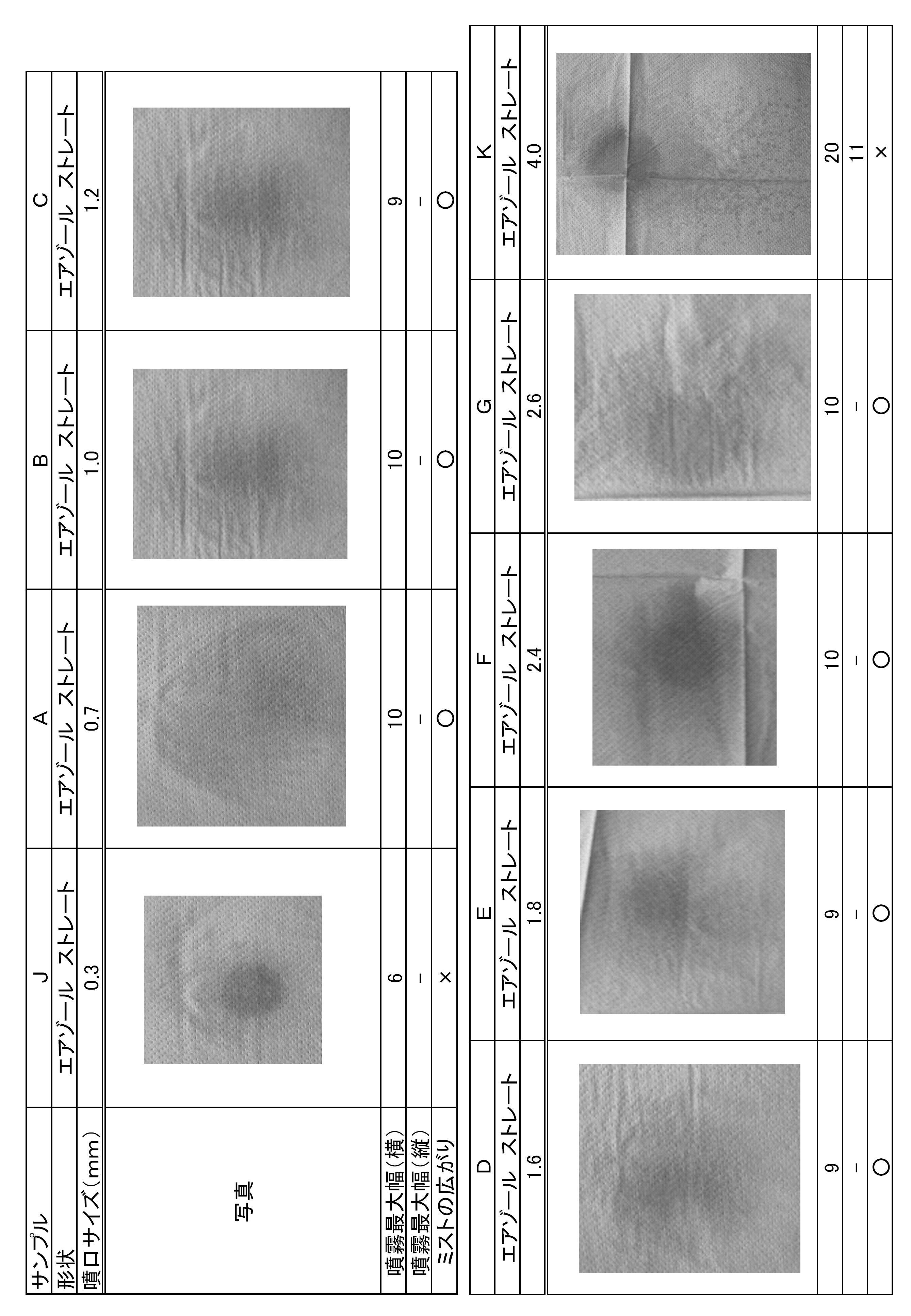
サンプルA~Eにて噴射した液体は、きれいな粒子になり、キムタオルが濡れる面積は適度に広く、全体的に均一に近いものであった。サンプルF、Gは、きれいな粒子になるが、粒がやや大きく、キムタオルが濡れる面積は、適度に広いものの、中央部にやや集中している。サンプルJは、きれいな粒子にならず、濡れる面積も狭く、中央に液体が集中した。サンプルKは、きれいな粒子にならず、ミストの粒径が大きいため、噴射の痕は縦に長い楕円状になり、かつ一部に液が集中した。これにより、内径サイズが小さすぎたり(本実施例では0.3mm)、大きすぎたり(本実施例では4.0mm)すると、きれいな粒子にならず、しかも噴射エリアは狭くなってしまう。これにより、きれいな粒子となり、噴射エリアが広範囲に及ぶ噴射口の内径範囲は、0.7mm~2.4mmであることがわかった。
以上の各実験から、バックグラウンドが35dBのときに噴射音を90dB以上とし、かつ液体を霧状に噴射するためには、噴射口の内径範囲を1.0mm~2.0mmとすればよいことがわかった。
以上、本発明の実施形態について説明したが、本発明はこれに限定されるものではなく種々の変更が可能である。噴射流路は、ストレートタイプではなく、いわゆるメカニカルブレークアップタイプでもよい。第2実施形態や第3実施形態のエアゾール噴射装置でも、第1実施形態の変形例のように噴射ノズルを有さないタイプの噴射ボタンとすることができる。液体の成分は問わず、清涼剤が含まれていないものであってもよい。第2噴射流路の断面形状は円形に限らず、楕円、多角形等種々の形状とすることができ、長さ寸法は種々のものとできる。
6、7、17、27 噴射流路
11、21、31 噴射口
12、22、32 微粒子発生部
D 内径
Claims (6)
-
内部に封入された噴射剤を含む液体を、噴射流路を介して噴射するエアゾール噴射装置において、
前記噴射流路の噴射口に、バックグラウンドが35dBのときの噴射音を90dB以上とし、かつ液体を霧状に噴射する微粒子発生部を備えたことを特徴とするエアゾール噴射装置。
-
前記微粒子発生部は、前記噴射流路の内径を1.0mm~2.0mmとして構成したことを特徴とする請求項1のエアゾール噴射装置。
-
前記微粒子発生部は、前記噴射流路の内径を1.2mm~1.8mmとして構成したことを特徴とする請求項1のエアゾール噴射装置。
-
前記噴射流路をストレートタイプとしたことを特徴とする請求項1~請求項3のいずれか1項のエアゾール噴射装置。
-
靴の内部側に対して前記液体を噴射するものであることを特徴とする請求項1~請求項4のいずれか1項のエアゾール噴射装置。
-
前記噴射剤は、液化石油ガス又はジメチルエーテルであることを特徴とする請求項1~請求項5のいずれか1項のエアゾール噴射装置。
Applications Claiming Priority (2)
| Application Number | Priority Date | Filing Date | Title |
|---|---|---|---|
| JP2010-269713 | 2010-12-02 | ||
| JP2010269713A JP5972528B2 (ja) | 2010-12-02 | 2010-12-02 | エアゾール噴射装置 |
Publications (1)
| Publication Number | Publication Date |
|---|---|
| WO2012074045A1 true WO2012074045A1 (ja) | 2012-06-07 |
Family
ID=46171970
Family Applications (1)
| Application Number | Title | Priority Date | Filing Date |
|---|---|---|---|
| PCT/JP2011/077788 Ceased WO2012074045A1 (ja) | 2010-12-02 | 2011-12-01 | エアゾール噴射装置 |
Country Status (2)
| Country | Link |
|---|---|
| JP (1) | JP5972528B2 (ja) |
| WO (1) | WO2012074045A1 (ja) |
Cited By (1)
| Publication number | Priority date | Publication date | Assignee | Title |
|---|---|---|---|---|
| EP2767346A3 (de) * | 2013-02-16 | 2014-11-19 | Aptar Radolfzell GmbH | Spender mit einer Lochplattendüse zum Austrag von Flüssigkeiten |
Families Citing this family (4)
| Publication number | Priority date | Publication date | Assignee | Title |
|---|---|---|---|---|
| JP3323812B2 (ja) * | 1998-07-16 | 2002-09-09 | 日本碍子株式会社 | 膜面に形成されたファウリング層の除去方法 |
| JP6222735B2 (ja) * | 2013-03-25 | 2017-11-01 | 株式会社マンダム | 冷却用エアゾール製品 |
| JP6505633B2 (ja) * | 2016-05-23 | 2019-04-24 | 小林製薬株式会社 | エアゾール噴射装置 |
| WO2019117216A1 (ja) * | 2017-12-13 | 2019-06-20 | アース製薬株式会社 | 定量噴射型エアゾール製品および定量噴射型エアゾール製品の使用方法 |
Citations (4)
| Publication number | Priority date | Publication date | Assignee | Title |
|---|---|---|---|---|
| JP2000025860A (ja) * | 1998-07-03 | 2000-01-25 | Osaka Ship Building Co Ltd | ノズル構造およびそれを用いたエアゾール製品 |
| JP2001293402A (ja) * | 2000-04-13 | 2001-10-23 | Daizo:Kk | エアゾール製品 |
| JP2003106724A (ja) * | 2001-09-28 | 2003-04-09 | Lion Corp | 靴ムレ改善スプレー |
| JP2009000353A (ja) * | 2007-06-22 | 2009-01-08 | Lion Corp | 液状エアゾール型制汗剤製品及びエアゾール用押釦 |
Family Cites Families (3)
| Publication number | Priority date | Publication date | Assignee | Title |
|---|---|---|---|---|
| JPH11128776A (ja) * | 1997-10-29 | 1999-05-18 | Yoshino Kogyosho Co Ltd | エアゾール用噴出ノズル |
| JP2007031479A (ja) * | 2005-07-22 | 2007-02-08 | Toyo Aerosol Ind Co Ltd | 噴霧用エアゾール組成物およびエアゾール製品 |
| JP4879099B2 (ja) * | 2007-06-22 | 2012-02-15 | 株式会社安部日鋼工業 | シースの支持構造 |
-
2010
- 2010-12-02 JP JP2010269713A patent/JP5972528B2/ja active Active
-
2011
- 2011-12-01 WO PCT/JP2011/077788 patent/WO2012074045A1/ja not_active Ceased
Patent Citations (4)
| Publication number | Priority date | Publication date | Assignee | Title |
|---|---|---|---|---|
| JP2000025860A (ja) * | 1998-07-03 | 2000-01-25 | Osaka Ship Building Co Ltd | ノズル構造およびそれを用いたエアゾール製品 |
| JP2001293402A (ja) * | 2000-04-13 | 2001-10-23 | Daizo:Kk | エアゾール製品 |
| JP2003106724A (ja) * | 2001-09-28 | 2003-04-09 | Lion Corp | 靴ムレ改善スプレー |
| JP2009000353A (ja) * | 2007-06-22 | 2009-01-08 | Lion Corp | 液状エアゾール型制汗剤製品及びエアゾール用押釦 |
Cited By (3)
| Publication number | Priority date | Publication date | Assignee | Title |
|---|---|---|---|---|
| EP2767346A3 (de) * | 2013-02-16 | 2014-11-19 | Aptar Radolfzell GmbH | Spender mit einer Lochplattendüse zum Austrag von Flüssigkeiten |
| US9463476B2 (en) | 2013-02-16 | 2016-10-11 | Aptar Radolfzell Gmbh | Dispenser for dispensing liquids |
| US10099229B2 (en) | 2013-02-16 | 2018-10-16 | Aptar Radolfzell Gmbh | Dispenser for dispensing liquids |
Also Published As
| Publication number | Publication date |
|---|---|
| JP5972528B2 (ja) | 2016-08-17 |
| JP2012115792A (ja) | 2012-06-21 |
Similar Documents
| Publication | Publication Date | Title |
|---|---|---|
| Liu et al. | The effects of the spraying pressure and nozzle orifice diameter on the atomizing rules and dust suppression performances of an external spraying system in a fully-mechanized excavation face | |
| JP5972528B2 (ja) | エアゾール噴射装置 | |
| KR20200065011A (ko) | 장치 및 유닛 | |
| BR112019010499A2 (pt) | cabeça para dispensação de material fluido | |
| CN212728792U (zh) | 一种电子雾化组件及其装置 | |
| KR101661575B1 (ko) | 스프레이 오리피스 구조 | |
| JP6505633B2 (ja) | エアゾール噴射装置 | |
| JP4166766B2 (ja) | エアゾール製品 | |
| JP2011177677A (ja) | エアゾールボタンおよびエアゾールキャップ | |
| JP5342848B2 (ja) | エアゾール容器用噴射ノズル | |
| JP2008168266A (ja) | 混相ミスト噴霧システム | |
| JPH01256975A (ja) | 活性物質噴霧装置 | |
| JP7351045B2 (ja) | 内容物噴射操作ボタンおよびこの内容物噴射操作ボタンを備えたエアゾール式製品 | |
| JP4960769B2 (ja) | エアゾール用押釦 | |
| JP2007031479A (ja) | 噴霧用エアゾール組成物およびエアゾール製品 | |
| JP2014136686A (ja) | 害虫駆除用エアゾール | |
| JP6144066B2 (ja) | エアゾール容器用噴射ボタン | |
| JP5596315B2 (ja) | エアゾール装置のノズル | |
| JP2017214137A (ja) | 発泡性内容物用の吐出部材 | |
| JP2010069421A (ja) | 噴射釦 | |
| JP2019209414A (ja) | ノズル、及びドライアイス噴射装置 | |
| JP3749927B2 (ja) | エアゾール装置のノズル | |
| JP3976476B2 (ja) | 泡吐出容器 | |
| JP2010274949A (ja) | エアゾール内容物噴射装置 | |
| JP2024064173A (ja) | エアゾール容器およびエアゾール製品 |
Legal Events
| Date | Code | Title | Description |
|---|---|---|---|
| 121 | Ep: the epo has been informed by wipo that ep was designated in this application |
Ref document number: 11845040 Country of ref document: EP Kind code of ref document: A1 |
|
| NENP | Non-entry into the national phase |
Ref country code: DE |
|
| 122 | Ep: pct application non-entry in european phase |
Ref document number: 11845040 Country of ref document: EP Kind code of ref document: A1 |