WO2012073772A1 - 珪素含有鋼スラブの熱間圧延方法 - Google Patents
珪素含有鋼スラブの熱間圧延方法 Download PDFInfo
- Publication number
- WO2012073772A1 WO2012073772A1 PCT/JP2011/076982 JP2011076982W WO2012073772A1 WO 2012073772 A1 WO2012073772 A1 WO 2012073772A1 JP 2011076982 W JP2011076982 W JP 2011076982W WO 2012073772 A1 WO2012073772 A1 WO 2012073772A1
- Authority
- WO
- WIPO (PCT)
- Prior art keywords
- mass
- slab
- steel
- temperature
- rate
- Prior art date
- Legal status (The legal status is an assumption and is not a legal conclusion. Google has not performed a legal analysis and makes no representation as to the accuracy of the status listed.)
- Ceased
Links
Images

Classifications
-
- C—CHEMISTRY; METALLURGY
- C22—METALLURGY; FERROUS OR NON-FERROUS ALLOYS; TREATMENT OF ALLOYS OR NON-FERROUS METALS
- C22C—ALLOYS
- C22C38/00—Ferrous alloys, e.g. steel alloys
- C22C38/04—Ferrous alloys, e.g. steel alloys containing manganese
-
- C—CHEMISTRY; METALLURGY
- C21—METALLURGY OF IRON
- C21D—MODIFYING THE PHYSICAL STRUCTURE OF FERROUS METALS; GENERAL DEVICES FOR HEAT TREATMENT OF FERROUS OR NON-FERROUS METALS OR ALLOYS; MAKING METAL MALLEABLE, e.g. BY DECARBURISATION OR TEMPERING
- C21D6/00—Heat treatment of ferrous alloys
- C21D6/008—Heat treatment of ferrous alloys containing Si
-
- C—CHEMISTRY; METALLURGY
- C21—METALLURGY OF IRON
- C21D—MODIFYING THE PHYSICAL STRUCTURE OF FERROUS METALS; GENERAL DEVICES FOR HEAT TREATMENT OF FERROUS OR NON-FERROUS METALS OR ALLOYS; MAKING METAL MALLEABLE, e.g. BY DECARBURISATION OR TEMPERING
- C21D8/00—Modifying the physical properties of ferrous metals or ferrous alloys by deformation combined with, or followed by, heat treatment
- C21D8/12—Modifying the physical properties of ferrous metals or ferrous alloys by deformation combined with, or followed by, heat treatment during manufacturing of articles with special electromagnetic properties
-
- C—CHEMISTRY; METALLURGY
- C21—METALLURGY OF IRON
- C21D—MODIFYING THE PHYSICAL STRUCTURE OF FERROUS METALS; GENERAL DEVICES FOR HEAT TREATMENT OF FERROUS OR NON-FERROUS METALS OR ALLOYS; MAKING METAL MALLEABLE, e.g. BY DECARBURISATION OR TEMPERING
- C21D8/00—Modifying the physical properties of ferrous metals or ferrous alloys by deformation combined with, or followed by, heat treatment
- C21D8/12—Modifying the physical properties of ferrous metals or ferrous alloys by deformation combined with, or followed by, heat treatment during manufacturing of articles with special electromagnetic properties
- C21D8/1216—Modifying the physical properties of ferrous metals or ferrous alloys by deformation combined with, or followed by, heat treatment during manufacturing of articles with special electromagnetic properties characterised by the working steps
- C21D8/1222—Hot rolling
-
- C—CHEMISTRY; METALLURGY
- C21—METALLURGY OF IRON
- C21D—MODIFYING THE PHYSICAL STRUCTURE OF FERROUS METALS; GENERAL DEVICES FOR HEAT TREATMENT OF FERROUS OR NON-FERROUS METALS OR ALLOYS; MAKING METAL MALLEABLE, e.g. BY DECARBURISATION OR TEMPERING
- C21D9/00—Heat treatment, e.g. annealing, hardening, quenching or tempering, adapted for particular articles; Furnaces therefor
- C21D9/46—Heat treatment, e.g. annealing, hardening, quenching or tempering, adapted for particular articles; Furnaces therefor for sheet metals
-
- C—CHEMISTRY; METALLURGY
- C22—METALLURGY; FERROUS OR NON-FERROUS ALLOYS; TREATMENT OF ALLOYS OR NON-FERROUS METALS
- C22C—ALLOYS
- C22C38/00—Ferrous alloys, e.g. steel alloys
- C22C38/001—Ferrous alloys, e.g. steel alloys containing N
-
- C—CHEMISTRY; METALLURGY
- C22—METALLURGY; FERROUS OR NON-FERROUS ALLOYS; TREATMENT OF ALLOYS OR NON-FERROUS METALS
- C22C—ALLOYS
- C22C38/00—Ferrous alloys, e.g. steel alloys
- C22C38/02—Ferrous alloys, e.g. steel alloys containing silicon
Definitions
- the present invention relates to a method for hot rolling silicon-containing steel slabs used for materials such as electromagnetic steel sheets, and more specifically, a method for heating silicon-containing steel slabs effective for preventing the occurrence of surface defects in hot rolling. It is about.
- Electrical steel sheets that are widely used as core materials for electrical equipment such as transformers and motors are broadly classified into directional electrical steel sheets and non-oriented electrical steel sheets.
- These electromagnetic steel sheets are manufactured from steel slabs containing silicon (Si) at a maximum of about 5.0 mass% for the purpose of reducing iron loss.
- the steel slab contains components such as C, Mn, Al, N, S, and Se as inhibitor components for causing secondary recrystallization, or improvement of metal structure and strength. Therefore, it is added for various purposes.
- a typical manufacturing process for the electrical steel sheet is to reheat a steel slab having the above-mentioned various components, hot-roll it into a hot-rolled sheet, and heat it as necessary.
- After performing the sheet annealing after making a cold rolled sheet of the final thickness by one or more cold rolling or two or more cold rolling sandwiching the intermediate annealing, and then recrystallizing the cold rolled sheet
- a product is formed by coating an insulating film.
- the steel slab having the above-mentioned various components is reheated, hot-rolled to form a hot-rolled sheet, and subjected to hot-rolled sheet annealing as necessary, and then cooled once.
- a cold rolled sheet with a final thickness is obtained by cold rolling or intermediate rolling with two or more cold rollings, followed by primary recrystallization annealing that also serves to decarburize the cold rolled sheet, and then the annealing separator is applied to the steel sheet surface.
- the product is applied to the substrate, subjected to finish annealing that serves as secondary recrystallization and purification, and is subjected to planarization treatment that serves also as an insulating coating.
- the surface defects generated in the hot rolling stage There is a problem that the steel plate is broken or other surface flaws are generated due to this, and the manufacturability is significantly impaired.
- the minute surface flaws do not lead to the fracture of the steel sheet, but are manifested by cold rolling, causing irregularities on the steel sheet surface, non-uniform thickness of the insulation coating, or even product Not only the surface quality of the steel sheet but also the magnetic properties are degraded. Therefore, it is preferable to reduce surface defects generated during hot rolling as much as possible.
- the hot rolling end temperature is caused by S by controlling it within a specific temperature range obtained from the ratio of the amount of Mn contained and the amount of S.
- a technique for avoiding hot brittleness and preventing surface flaws after hot rolling is disclosed.
- a steel slab is heated to a temperature range in which at least a part of the grain boundary segregation is melted in a protective gas atmosphere, and then heated and held in a specific temperature range for hot rolling.
- a technique for preventing surface flaws caused by grain coarsening is disclosed.
- Patent Document 3 discloses that the surface of the slab surface caused by precipitation of AlN by performing slab heating in an atmosphere having a nitrogen partial pressure P N2 of 0.5 atm or less, with heating by heating or induction heating. Techniques for preventing wrinkles are disclosed. Further, Patent Document 4 discloses that a transfer table and a transfer table are controlled by limiting the transfer distance to the first pass of hot rough rolling after extraction from the slab heating furnace and controlling the reduction amount of the first pass to 20 to 40 mm. A technique for preventing surface flaws by reducing the starting point of cracks due to contact and reducing the surface crystal grains is disclosed.
- the present invention has been made in view of the above problems, and its purpose is to provide advantageous hot rolling that reduces surface flaws generated in a hot-rolled sheet made of a silicon-containing steel slab having a specific component system. To propose a method.
- the inventors have conducted intensive studies on the elucidation of the generation mechanism and the prevention measures.
- the surface defects generated during the above hot rolling are completely different from the conventionally considered mechanism, and are caused by slab surface cracks caused by the difference in the heating rate between the slab surface layer and the inside, and
- the present invention relates to C: 0.03 mass% or less, Si: 2.0 to 5.0 mass%, Mn: 0.005 to 1.0 mass%, sol.
- the temperature increase rate of the steel slab in the above reheating is defined as R 1 (° C./min) from the start of reheating to 750 ° C. and R 2 (° C./min) from 750 ° C. to 1050 ° C.
- R 1 and R 2 are This is a hot rolling method for a silicon-containing steel slab that is reheated so as to satisfy the relationship of 20 ° C./min ⁇ R 2 ⁇ R 1 ⁇ 2 ° C./min.
- the steel slab in the hot rolling method of the present invention further includes Ni: 0.005 to 1.5 mass%, Sn: 0.005 to 0.50 mass%, Sb: 0.005 to Contains one or more selected from 0.50 mass%, Cu: 0.005 to 1.5 mass%, P: 0.005 to 0.50 mass%, and Cr: 0.005 to 1.5 mass% May be.
- the inventors first investigated a component system in which surface defects are likely to occur during hot rolling, among silicon-containing steel slabs having various component systems. As a result, a specific component system, that is, C: 0.03 mass% or less, Si: 2.0 to 5.0 mass%, Mn: 0.005 to 1.0 mass%, sol. In steel slabs containing Al: 0.040 mass% or less, N: 0.0005 to 0.0150 mass%, and S + Se: 0.030 mass% or less, it was revealed that the occurrence rate of surface defects was high.
- Table 1 shows the surface flaw occurrence rate of a hot-rolled sheet rolled from a steel slab having three component compositions of X, Y, and Z.
- Steel X satisfying the above conditions is the other steel Y or Compared with Z, it can be seen that the surface flaw occurrence rate is remarkably high.
- the surface flaw occurrence rate of the steel sheet was determined by inspecting the surface of the steel sheet for the entire length of the hot rolled coil with a CCD camera (Charge-Coupled device camera) and determining whether or not surface flaws occurred in units of 10 cm ⁇ 10 cm. This is the area ratio of the part that is determined to have surface defects.
- CCD camera Charge-Coupled device camera
- the inventors collected tensile test pieces from the slab surface layers of the steels X, Y and Z and used them for the high-temperature tensile test. did.
- the tensile test applied strains up to 1% at two levels of strain rates of 2 ⁇ 10 ⁇ 6 / s and 2 ⁇ 10 ⁇ 3 / s at various temperatures from 700 ° C. to 1100 ° C. The elongation strain of was measured.
- the steel X having a small C content and a large amount of N exhibits remarkable brittleness at a low strain rate (2 ⁇ 10 ⁇ 6 / s) in the temperature range near 900 ° C., and the elongation strain amount is only 0. It became clear that grain boundary cracking occurred at 2%. Note that no cracks occurred at a strain rate of 2 ⁇ 10 ⁇ 3 / s. On the other hand, the steel Y with a low N content and the steel Z with a high C content did not crack at any temperature and strain rate.
- the inventors investigated the cross-sectional structure of the specimen after the tensile test of the steels X, Y, and Z, and found that a large amount of AlN and Si 3 N 4 were precipitated at the grain boundaries of the steel X. On the other hand, no grain boundary precipitates were observed in the steel Y. Further, since a pearlite phase was confirmed in the vicinity of the grain boundary of the steel Z, it was considered that an austenite phase was generated in the vicinity of the grain boundary during high-temperature heating. From these facts, the remarkable embrittlement at 900 ° C. in the steel X is caused by a decrease in grain boundary strength due to precipitation of AlN or Si 3 N 4 at the ferrite grain boundaries, It was inferred that the formation of the austenite phase in the vicinity had the effect of increasing the grain boundary strength.
- the temperature of the slab surface layer when the slab is reheated is higher than that inside the slab, and the temperature difference is usually larger as the heating rate is higher.
- the slab heating rate decreases as the temperature increases, and as a result, the temperature difference between the surface layer and the inside also decreases.
- tensile strain is generated in the slab surface due to thermal expansion in the slab.
- the tensile strain at this time is estimated to be about 0.2% and a strain rate of about 2 ⁇ 10 ⁇ 6 / s at a slab temperature of 700 to 1000 ° C., which is consistent with the above-described embrittlement conditions. I know you will.
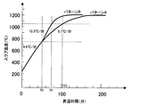
- the inventors increased the temperature rising rate near 900 ° C. when reheating the slab, that is, increased the temperature rising rate near 900 ° C., and increased the temperature rising rate of the slab surface layer from the inside of the slab. If it raises, it thinks that the crack by the tensile strain of a slab surface layer can be prevented, and the temperature rise rate in 900 degreeC vicinity of the steel slab of the steel X mentioned above is 2 of the pattern A and the pattern B shown in FIG. Reheating was performed under one condition, and hot rolling was performed, and the occurrence rate of surface defects generated on the hot-rolled sheet was investigated.
- the heating rate of 750 ° C. or less in FIG. 1 is 9.6 ° C./min for both pattern A and pattern B, and the heating rate from 750 to 1050 ° C. is 5.7 ° C./min for pattern A
- Pattern B was 12.3 ° C./min.
- C 0.03 mass% or less C is added to the grain oriented electrical steel sheet with an upper limit of about 0.1 mass% for the purpose of improving the metal structure.
- the austenite phase in the vicinity of the grain boundary increases, so that brittleness at a high temperature and a low strain rate is suppressed, so that it is not necessary to apply the present invention. That is, the present invention is an effective technique in a component system in which brittleness at a high temperature and a low strain rate is a problem. Therefore, in this invention, content of C is limited to 0.03 mass% or less from which the said brittleness becomes a problem. In principle, C may be 0 mass%.
- Si 2.0 to 5.0 mass% Si is an element effective for increasing the electric resistance of steel and reducing iron loss. However, when the Si content exceeds 5.0 mass%, the cold rolling property is remarkably lowered, so 5.0 mass% is set as the upper limit. On the other hand, when Si is less than 2.0 mass%, the austenite phase near the grain boundary increases, and as described above, brittleness at high temperature and low strain rate is suppressed. That is, such a slab surface crack does not become a problem in a steel slab containing no Si. Therefore, in the present invention, Si is in the range of 2.0 to 5.0 mass%.
- Mn 0.005 to 1.0 mass%
- Mn is usually contained in an amount of 0.005 mass% or more as an impurity.
- Mn exceeds 1.0 mass%, the austenite phase near the grain boundary increases, and brittleness at high temperature and low strain rate is suppressed. Therefore, in the present invention, Mn is in the range of 0.005 to 1.0 mass%.
- Al is 0.040 mass% or less as Al.
- Al is sol. Al may be added up to 0.040 mass% as an upper limit.
- Al is an element effective for increasing the electric resistance of steel and reducing iron loss, similarly to Si. Therefore, in non-oriented electrical steel sheets, it may be added up to 2.0 mass%. is there.
- sol. When Al exceeds 0.040 mass%, AlN precipitates in the grains and does not precipitate at the grain boundaries, so that brittleness is not a problem. Therefore, in the present invention, sol. Al is limited to 0.040 mass% or less.
- Al added as a deoxidizer may be contained as an impurity in less than 0.010 mass% (over 0 mass%).
- N 0.0005 to 0.0150 mass%
- N is an element that forms Al and AlN, Si and Si 3 N 4 and precipitates at grain boundaries, and promotes brittleness at high temperature and low strain rate as described above. 0.015 mass% may be added to the upper limit. However, when N is less than 0.0005 mass%, the amount of precipitation at the grain boundary is small, and brittleness at high temperature and low strain rate is not a problem. Therefore, in the present invention, N is in the range of 0.0005 to 0.0150 mass%. In the grain-oriented electrical steel sheet or non-oriented electrical steel sheet, N of less than 0.010 mass% (more than 0 mass%) may be contained as an impurity.
- S and Se 0.030 mass% or less in total S and Se are impurities in non-oriented electrical steel sheets, S is less than 0.010 mass% (greater than 0 mass%), and Se is less than 0.0010 mass% (greater than 0 mass%) May be contained.
- the total of S and Se may be added as an inhibitor with an upper limit of 0.030 mass%. Therefore, in the present invention, S and Se are set to 0.030 mass% or less in total.
- the steel slab of this invention may contain the 1 type (s) or 2 or more types chosen from Ni, Sn, Sb, Cu, P, and Cr other than the said component in the following range.
- Ni 0.005 to 1.5 mass%
- Ni is an element that improves the magnetic properties by improving the structure of the hot-rolled sheet. However, if the content is less than 0.005 mass%, the effect of improving the magnetic properties is small. On the other hand, if the content exceeds 1.5 mass%, the secondary recrystallization in the grain-oriented electrical steel sheet becomes unstable and the magnetic properties deteriorate. . Therefore, Ni is preferably added in the range of 0.005 to 1.5 mass%.
- Sn 0.005 to 0.50 mass%
- Sb 0.005 to 0.50 mass%
- Cu 0.005 to 1.5 mass%
- P 0.005 to 0.50 mass%
- Cr 0.005 to 1.5 mass%
- Sn, Sb, Cu, P, and Cr are elements useful for improving iron loss, respectively, but if any of them is less than the lower limit of the above range, the effect of improving iron loss is small. Since the development of secondary recrystallized grains in the grain-oriented electrical steel sheet is inhibited, it is preferable to contain each in the above range. In the steel slab in the present invention, the balance other than the above components is Fe and inevitable impurities.
- the hot rolling method for the silicon-containing steel slab of the present invention will be described.
- the above-described steel adjusted to the component composition suitable for the present invention is melted by a process through a converter, an electric furnace, or further vacuum degassing, and the continuous casting method or the ingot-bundling rolling method.
- It is related to a hot rolling method in which a steel material (steel slab) is used and then the steel slab is reheated to a predetermined temperature and then hot rolled to obtain a hot rolled sheet having a predetermined thickness.
- the melting method, the method for forming the steel slab and the hot rolling conditions may be carried out in accordance with conventional methods and are not particularly limited.
- the reheating of the steel slab must be performed while satisfying the following conditions. That is, according to the present invention, the reheating of the steel slab is performed by setting the heating rate from the start of reheating of the slab to the slab temperature of 750 ° C. by R 1 (° C./min), and increasing the heating rate from the slab temperature of 750 ° C. to 1050 ° C. by R. 2 (° C./min), R 1 and R 2 are represented by the following formula: It is necessary to reheat the steel slab to satisfy 20 ° C./min ⁇ R 2 ⁇ R 1 ⁇ 2 ° C./min.
- the slab temperature is the average temperature in the slab thickness direction
- the rate of temperature increase is the rate of temperature increase in the average temperature in the slab thickness direction.
- the heating rate R 2 from 750 to 1050 ° C. is heated so as to be equal to or higher than the heating rate R 1 up to 750 ° C.
- R 2 is less than R 1
- the slab surface layer and the interior increase near 900 ° C. This is because a tensile strain is generated in the slab surface layer due to the temperature speed difference, a grain boundary crack is generated in the slab surface layer due to the tensile strain, and surface flaws are generated after hot rolling.
- R 1 and R 2 are set to 2 ° C./min or more is that if it is less than 2 ° C./min, it takes a very long time to reheat the slab, which is not practical.
- the relationship between the heating rate R 1 from re-start of heating the slab to 750 ° C., a heating rate of 750 to 1050 ° C. and R 2 is a R 2 ⁇ R 1 It was. This is because the greater the difference between the furnace temperature of the heating furnace and the slab temperature, the greater the heat input to the slab surface, and the greater the rate of slab heating, that is, the lower the slab temperature, the greater the rate of temperature increase. Because it becomes. In other words, the higher the slab temperature, the lower the rate of temperature increase, and the rate of temperature increase inside the slab surface and the inside are reversed, and cracks are likely to occur in the slab surface layer. Therefore, in the present invention, contrary to the conventional heating, the temperature rising rate at a high temperature is made larger than when the slab temperature is low.
- the furnace temperature is controlled so as to meet the above conditions while monitoring the temperature history of each slab by measurement or calculation. Slab temperature control management is required.
- the hot-rolled sheet of the present invention thus obtained is excellent in surface quality, after that, if it is a grain-oriented electrical steel sheet or non-oriented electrical steel sheet in the manufacturing process described above, without impairing productivity, High quality products can be obtained.
- the rate of temperature increase up to 0 ° C. is R 1
- the rate of temperature increase from 750 ° C. to 1050 ° C. is R 2
- these R 1 and R 2 are variously changed and reheated to 1100 ° C., and then hot rolled.
- a hot-rolled sheet with a thickness of 2.5 mm was used, and the occurrence rate of surface defects generated on the hot-rolled sheet was investigated.
- the surface flaw occurrence rate is determined by observing the entire length of the front and back surfaces of the hot-rolled coil with a CCD camera, determining the presence or absence of surface flaws in units of 10 cm ⁇ 10 cm, and determining the area ratio of the surface of the steel sheet determined to have surface flaws. It was.
- FIG. 2 shows the result of the above measurement.
- the steel slabs having various composition shown in Table 2 were subjected to the two slab reheating patterns shown in FIG. 1, that is, the heating rate of 750 ° C. or less was set to 9.6 ° C./min for both patterns A and B.
- the heating rate from 750 to 1050 ° C. was reheated to 1200 ° C. at 5.7 ° C./min for pattern A and 12.3 ° C./min for pattern B.
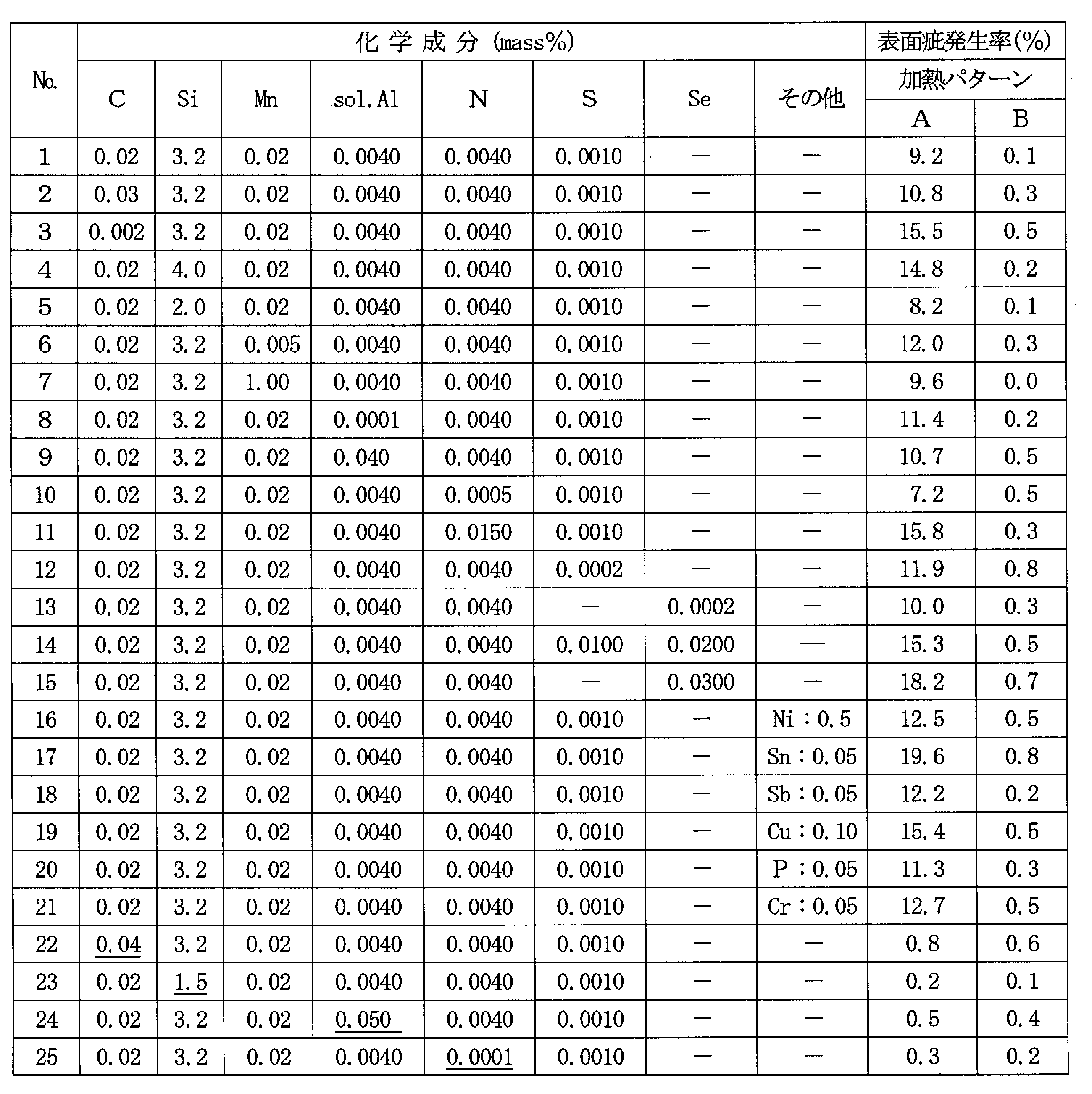
- the rate of occurrence of surface defects generated on the hot-rolled sheet was measured in the same manner as in Example 1, and the results are also shown in Table 2. From Table 2, No. out of the component composition range of the present invention where surface flaws hardly occur.
- the occurrence rate of surface defects is low regardless of the heating pattern.
- the reheating pattern A that does not meet the conditions of the present invention has a high incidence of surface flaws, It can be seen that the occurrence rate of surface flaws can be remarkably reduced by employing the reheating pattern B suitable for the present invention.
- the technique of the present invention can be applied not only to hot rolling of silicon-containing steel slabs but also to hot rolling of steel slabs of other steel types in which cracks occur by the same mechanism.
Landscapes
- Chemical & Material Sciences (AREA)
- Engineering & Computer Science (AREA)
- Mechanical Engineering (AREA)
- Organic Chemistry (AREA)
- Metallurgy (AREA)
- Materials Engineering (AREA)
- Physics & Mathematics (AREA)
- Crystallography & Structural Chemistry (AREA)
- Thermal Sciences (AREA)
- Manufacturing & Machinery (AREA)
- Electromagnetism (AREA)
- Manufacturing Of Steel Electrode Plates (AREA)
- Metal Rolling (AREA)
Abstract
C:0.03mass%以下、Si:2.0~5.0mass%、Mn:0.005~1.0mass%、sol.Al:0.040mass%以下、N:0.0005~0.0150mass%、S+Se:0.030mass%以下を含有し、残部がFeおよび不可避的不純物からなる成分組成を有する鋼スラブを再加熱し、熱間圧延するに当たり、上記再加熱における鋼スラブの昇温速度を、再加熱開始から750℃までをR1(℃/分)、750℃~1050℃までをR2(℃/分)とするとき、R1およびR2が、20℃/分≧R2≧R1≧2℃/分、の関係を満たすように再加熱した後、熱間圧延することにより、熱延板において発生する表面疵を低減する。
Description
本発明は、電磁鋼板などの素材に用いられる珪素含有鋼スラブの熱間圧延方法に関し、具体的には、熱間圧延における表面疵の発生を防止するのに有効な珪素含有鋼スラブの加熱方法に関するものである。
変圧器やモーターなどの電気機器の鉄心材料として広く使用されている電磁鋼板は、方向性電磁鋼板と無方向性電磁鋼板に大別される。これらの電磁鋼板は、鉄損の低減を目的として、最大で5.0mass%程度の珪素(Si)を含有する鋼スラブを素材として製造されている。さらに、上記鋼スラブには、Siの他に、C,Mn,Al,N,S,Seなどの成分が、二次再結晶を起こさせるためのインヒビター成分として、あるいは金属組織の改善や強度向上のため等、種々の目的をもって添加されている。
上記電磁鋼板の代表的な製造プロセスは、例えば、無方向性電磁鋼板の場合には、上記各種成分を有する鋼スラブを再加熱し、熱間圧延して熱延板とし、必要に応じて熱延板焼鈍を施した後、1回の冷間圧延または中間焼鈍を挟む2回以上の冷間圧延により最終板厚の冷延板とし、その後、この冷延板に再結晶焼鈍を施した後、絶縁被膜を被成して製品とするのが一般的である。
また、方向性電磁鋼板の場合には、上記各種成分を有する鋼スラブを再加熱し、熱間圧延して熱延板とし、必要に応じて熱延板焼鈍を施した後、1回の冷間圧延または中間焼鈍を挟む2回以上の冷間圧延により最終板厚の冷延板とし、その後、この冷延板に脱炭を兼ねた一次再結晶焼鈍を施してから焼鈍分離剤を鋼板表面に塗布し、二次再結晶と純化を兼ねた仕上焼鈍を施し、絶縁被膜の被成を兼ねた平坦化焼鈍を施して製品とするのが一般的である。
上記電磁鋼板の製造プロセスでは、特に、冷間圧延や連続焼鈍のように、コイルではなく、コイルを巻き戻した鋼板の状態で処理する製造プロセスにおいては、熱間圧延段階で発生した表面疵によって、鋼板が破断したり、それが原因で他の表面疵を発生させたりして、製造性が著しく害されるという問題がある。また、微小な表面疵は、鋼板の破断にまで至らぬものの、冷間圧延することによって顕在化し、鋼板表面に凹凸欠陥を生じたり、絶縁被膜の膜厚を不均一化したり、あるいはさらに、製品鋼板の表面品質だけでなく磁気特性の低下をも招いたりする。したがって、熱間圧延時に発生する表面疵は、できるだけ低減しておくことが好ましい。
この問題に対しては、例えば、特許文献1には、熱間圧延終了温度を、含有するMn量とS量との比から求められる特定の温度範囲内に制御することにより、Sに起因する熱間脆性を回避して熱間圧延後の表面疵を防止する技術が開示されている。また、特許文献2には、鋼スラブを保護ガス雰囲気中で粒界偏析の少なくとも一部が溶融する温度域まで加熱し、その後、特定温度域に加熱保持して熱間圧延することにより、結晶粒の粗大化に起因する表面疵を防止する技術が開示されている。また、特許文献3には、スラブの加熱を通電加熱または誘導加熱とし、窒素分圧PN2が0.5気圧以下の雰囲気中にて行うことにより、スラブ表面でのAlNの析出に起因する表面疵を防止する技術が開示されている。また、特許文献4には、スラブ加熱炉から抽出後、熱間粗圧延1パス目までの搬送距離を制限し、同1パス目の圧下量を20~40mmに制御することにより、搬送テーブルとの接触による割れの起点を低減させるとともに、表層の結晶粒を微細化させて表面疵を防止する技術が開示されている。
上記技術を適用することによって、熱延板の表面疵は大幅に低減されてきた。しかしながら、発明者らの最近の調査によれば、上記従来技術の適用によっては未だ十分に解消できていない熱間圧延時に発生する表面疵があること、特に、種々の鋼成分を有する珪素含有鋼スラブの中でも、ある特定の成分系の鋼スラブを素材とした熱延板において、その表面疵の発生率が高いということが明らかとなってきた。
本発明は、上記問題点に鑑みてなされたものであり、その目的は、ある特定の成分系の珪素含有鋼スラブを素材とした熱延板において発生する表面疵を低減する有利な熱間圧延方法を提案することにある。
発明者らは、上記課題を解決するべく、その発生メカニズムの解明とその防止策について、鋭意検討を重ねた。その結果、上記熱間圧延時に発生する表面疵は、従来、考えられていたメカニズムとはまったく異なる、スラブ表層と内部の昇温速度差に起因したスラブ表面割れに起因するものであること、そして、上記スラブ表面割れを防止するためには、割れが発生する900℃近辺における昇温速度を、それより低温域の昇温速度より高めてやることが有効であること見出し、本発明を開発するに至った。
すなわち、本発明は、C:0.03mass%以下、Si:2.0~5.0mass%、Mn:0.005~1.0mass%、sol.Al:0.040mass%以下、N:0.0005~0.0150mass%、S+Se:0.030mass%以下を含有し、残部がFeおよび不可避的不純物からなる成分組成を有する鋼スラブを再加熱し、熱間圧延するに当たり、上記再加熱における鋼スラブの昇温速度を、再加熱開始から750℃までをR1(℃/分)、750℃~1050℃までをR2(℃/分)とするとき、R1およびR2が下記式;
20℃/分≧R2≧R1≧2℃/分
の関係を満たすように再加熱する珪素含有鋼スラブの熱間圧延方法である。
20℃/分≧R2≧R1≧2℃/分
の関係を満たすように再加熱する珪素含有鋼スラブの熱間圧延方法である。
また、本発明の熱間圧延方法における鋼スラブは、上記成分組成に加えてさらに、Ni:0.005~1.5mass%、Sn:0.005~0.50mass%、Sb:0.005~0.50mass%、Cu:0.005~1.5mass%、P:0.005~0.50mass%およびCr:0.005~1.5mass%のうちから選ばれる1種または2種以上を含有してもよい。
本発明によれば、熱間圧延時に発生する表面疵を大幅に低減することができるので、後工程での生産トラブルを大幅に低減することができるとともに、表面品質だけでなく、磁気特性にも優れる高品質の電磁鋼板を安定して提供することが可能となる。
発明者らは、まず、種々の成分系を有する珪素含有鋼スラブの中で、特に熱間圧延時に表面疵が発生しやすい成分系について調査した。その結果、ある特定の成分系、すなわち、C:0.03mass%以下、Si:2.0~5.0mass%、Mn:0.005~1.0mass%、sol.Al:0.040mass%以下、N:0.0005~0.0150mass%、S+Se:0.030mass%以下を含有する鋼スラブにおいて、表面疵の発生率が高いということが明らかとなった。
表1は、X,YおよびZの3つの成分組成を有する鋼スラブから圧延された熱延板の表面疵発生率を示したものであり、上記条件を満たす鋼Xは、他の鋼YやZと比較し、著しく高い表面疵発生率を示していることがわかる。ここで、上記鋼板の表面疵発生率とは、熱延コイルの表裏全長の鋼板表面をCCDカメラ(Charge-Coupled device camera)で検査し、10cm×10cmを単位として表面疵の発生有無を判別したときの、表面疵ありと判別した部分の面積率のことをいう。

そこで、発明者らは、上記鋼スラブを素材とした熱延板の表面疵発生メカニズムを解明するため、鋼X,YおよびZのスラブ表層から、引張試験片を採取し、高温引張試験に供した。引張試験は、700℃から1100℃の種々の温度において、歪速度2×10⁻⁶/sと2×10-3/sの2水準で1%まで歪を付与し、引張開始から割れ発生までの伸び歪を測定した。その結果、C含有量が小さくかつNを多く含む鋼Xは、900℃付近の温度域では、低歪速度(2×10-6/s)で著しい脆性を示し、伸び歪量がわずか0.2%で粒界割れが発生することが明らかとなった。なお、2×10-3/sの歪速度では割れが生じなかった。一方、N含有量が低い鋼YおよびC含有量が高い鋼Zでは、いずれの温度、歪速度においても割れを生じなかった。
さらに、発明者らは、鋼X,YおよびZの引張試験後の試験片断面組織を調査したところ、鋼Xの粒界には、AlNやSi3N4が多量に析出していたのに対して、鋼Yには粒界析出物は確認されなかった。また、鋼Zの粒界付近にはパーライト相が確認されたことから、高温加熱時には粒界付近にオーステナイト相が生成していたものと考えられた。これらのことから、鋼Xにおける900℃での著しい脆化は、AlNやSi3N4がフェライト粒界に析出したことによって、粒界強度が低下したことが原因であること、また、粒界近傍におけるオーステナイト相の生成は、粒界強度を高める効果があることが推察された。
鋼が900℃付近の温度でかつ低歪速度で脆性を示すことは、従来から知られていた。しかし、脆性を示すとはいえ、いずれも割れ発生までの伸びは5%以上であり、上述したような0.2%という極めて小さな伸びで割れが発生する、しかも、ある特定の成分組成、温度および歪速度の条件下で発生するということは、今までまったく知られていなかったことである。
そこで、発明者らは、上記鋼Xにおいて表面疵が多く発生する原因は、上述した低歪速度での高温脆性にあると考え、その脆性を引き起こす原因について調査したところ、鋼スラブを再加熱する際の加熱条件、特に、900℃近傍における加熱速度が大きく関与していることがわかってきた。
すなわち、一般に、スラブを再加熱するときのスラブ表層の温度は、スラブ内部に比べて高く、その温度差は、昇温速度が大きいほど大きいのが普通である。一方、スラブ加熱速度は、通常の加熱方法では、高温になるほど低下し、その結果、表層と内部の温度差も小さくなる。この際、スラブ表層における昇温速度がスラブ内部より小さくなるような条件が生じたときには、スラブ内部の熱膨張によってスラブ表層に引張歪が発生することになる。そして、このときの引張歪は、スラブ温度700~1000℃では、歪量が0.2%程度で歪速度が2×10⁻⁶/s程度となると見積もられ、上述の脆化条件と一致することがわかってきた。
そこで、発明者らは、スラブを再加熱する際の900℃付近の昇温速度を高めてやれば、すなわち、900℃付近の昇温速度を高めて、スラブ表層の昇温速度をスラブ内部より高めてやれば、スラブ表層の引張歪による割れを防止できるのではと考え、上述した鋼Xの鋼スラブを、900℃付近における昇温速度を、図1に示したパターンAおよびパターンBの2つの条件で再加熱し、熱間圧延して、熱延板に生じた表面疵の発生率を調査した。ここで、図1における750℃以下の昇温速度は、パターンA、パターンBともに9.6℃/分とし、750から1050℃までの昇温速度は、パターンAは5.7℃/分、パターンBは12.3℃/分とした。
上記昇温速度を変えた実験の結果、表面疵の発生率は、パターンAでは9.8%、パターンBでは0.1%であった。この結果から、スラブ再加熱開始からスラブ温度750℃までの昇温速度に対して、750から1050℃までの昇温速度を大きくしてやることで、熱延板の表面疵発生率を大幅に低減できることが確認された。
本発明は、上記新規な知見に、さらに検討を加えてなされたものである。
本発明は、上記新規な知見に、さらに検討を加えてなされたものである。
次に、本発明の鋼スラブの成分組成を限定する理由について説明する。
C:0.03mass%以下
Cは、方向性電磁鋼板においては、金属組織の改善を目的として、0.1mass%程度を上限として添加される。しかし、C含有量が0.03mass%を超えると、粒界近傍のオーステナイト相が増加するため、高温、低歪速度での脆性は抑制されるので、本発明を適用する必要がなくなる。すなわち、本発明は、高温、低歪速度での脆性が問題となる成分系において有効な技術である。よって、本発明では、Cの含有量を、上記脆性が問題となる0.03mass%以下に限定する。なお、原理上、Cは0mass%であってもよい。
C:0.03mass%以下
Cは、方向性電磁鋼板においては、金属組織の改善を目的として、0.1mass%程度を上限として添加される。しかし、C含有量が0.03mass%を超えると、粒界近傍のオーステナイト相が増加するため、高温、低歪速度での脆性は抑制されるので、本発明を適用する必要がなくなる。すなわち、本発明は、高温、低歪速度での脆性が問題となる成分系において有効な技術である。よって、本発明では、Cの含有量を、上記脆性が問題となる0.03mass%以下に限定する。なお、原理上、Cは0mass%であってもよい。
Si:2.0~5.0mass%
Siは、鋼の電気抵抗を高めて鉄損を低減するのに有効な元素である。しかし、Si含有量が5.0mass%を超えると、冷間圧延性が著しく低下するので、5.0mass%を上限とする。一方、Siが2.0mass%未満では、粒界近傍のオーステナイト相が増加し、前述したように、高温、低歪速度での脆性は抑制される。すなわち、Siを含有しない鋼スラブでは、このようなスラブ表面割れが問題となることはない。よって、本発明では、Siは2.0~5.0mass%の範囲とする。
Siは、鋼の電気抵抗を高めて鉄損を低減するのに有効な元素である。しかし、Si含有量が5.0mass%を超えると、冷間圧延性が著しく低下するので、5.0mass%を上限とする。一方、Siが2.0mass%未満では、粒界近傍のオーステナイト相が増加し、前述したように、高温、低歪速度での脆性は抑制される。すなわち、Siを含有しない鋼スラブでは、このようなスラブ表面割れが問題となることはない。よって、本発明では、Siは2.0~5.0mass%の範囲とする。
Mn:0.005~1.0mass%
Mnは、通常、不純物として0.005mass%以上含有される。一方、Mnが1.0mass%を超えると、粒界近傍のオーステナイト相が増加し、高温、低歪速度での脆性は抑制される。よって、本発明では、Mnは0.005~1.0mass%の範囲とする。
Mnは、通常、不純物として0.005mass%以上含有される。一方、Mnが1.0mass%を超えると、粒界近傍のオーステナイト相が増加し、高温、低歪速度での脆性は抑制される。よって、本発明では、Mnは0.005~1.0mass%の範囲とする。
Al:sol.Alとして0.040mass%以下
Alは、方向性電磁鋼板においては、インヒビターとしてsol.Alで0.040mass%を上限として添加されることがある。また、Alは、Siと同様、鋼の電気抵抗を高めて鉄損を低減するのに有効な元素であるため、無方向性電磁鋼板においては、2.0mass%を上限として添加されることがある。しかし、sol.Alが0.040mass%超では、AlNは粒内に析出して粒界に析出しないため、脆性は問題とならない。そのため、本発明ではsol.Alを0.040mass%以下に制限する。なお、方向性電磁鋼板あるいは無方向性電磁鋼板では、脱酸剤として添加されたAlが、不純物として0.010mass%未満(0mass%超)含有されることがある。
Alは、方向性電磁鋼板においては、インヒビターとしてsol.Alで0.040mass%を上限として添加されることがある。また、Alは、Siと同様、鋼の電気抵抗を高めて鉄損を低減するのに有効な元素であるため、無方向性電磁鋼板においては、2.0mass%を上限として添加されることがある。しかし、sol.Alが0.040mass%超では、AlNは粒内に析出して粒界に析出しないため、脆性は問題とならない。そのため、本発明ではsol.Alを0.040mass%以下に制限する。なお、方向性電磁鋼板あるいは無方向性電磁鋼板では、脱酸剤として添加されたAlが、不純物として0.010mass%未満(0mass%超)含有されることがある。
N:0.0005~0.0150mass%
Nは、AlとAlN、SiとSi3N4を形成して粒界に析出し、前述した高温、低歪速度での脆性を促進する元素であるが、方向性電磁鋼板においては、インヒビターとして0.015mass%を上限に添加されることがある。しかし、Nが0.0005mass%未満では、粒界への析出量が少なく高温、低歪速度での脆性は問題とならない。よって、本発明では、Nは0.0005~0.0150mass%の範囲とする。なお、方向性電磁鋼板あるいは無方向性電磁鋼板では、不純物として0.010mass%未満(0mass%超)のNが含有されることがある。
Nは、AlとAlN、SiとSi3N4を形成して粒界に析出し、前述した高温、低歪速度での脆性を促進する元素であるが、方向性電磁鋼板においては、インヒビターとして0.015mass%を上限に添加されることがある。しかし、Nが0.0005mass%未満では、粒界への析出量が少なく高温、低歪速度での脆性は問題とならない。よって、本発明では、Nは0.0005~0.0150mass%の範囲とする。なお、方向性電磁鋼板あるいは無方向性電磁鋼板では、不純物として0.010mass%未満(0mass%超)のNが含有されることがある。
SおよびSe:合計で0.030mass%以下
SおよびSeは、無方向性電磁鋼板では不純物として、Sは0.010mass%未満(0mass%超)、Seは0.0010mass%未満(0mass%超)含有されることがある。また、方向性電磁鋼板においては、インヒビターとしてSとSeの合計で0.030mass%を上限に添加されることがある。そこで、本発明では、SとSeは合計で0.030mass%以下とする。
SおよびSeは、無方向性電磁鋼板では不純物として、Sは0.010mass%未満(0mass%超)、Seは0.0010mass%未満(0mass%超)含有されることがある。また、方向性電磁鋼板においては、インヒビターとしてSとSeの合計で0.030mass%を上限に添加されることがある。そこで、本発明では、SとSeは合計で0.030mass%以下とする。
なお、本発明の鋼スラブは、上記成分以外に、Ni,Sn,Sb,Cu,PおよびCrのうちから選ばれる1種または2種以上を、下記の範囲で含有していてもよい。
Ni:0.005~1.5mass%
Niは、熱延板の組織を改善して磁気特性を向上させる元素である。しかし、含有量が0.005mass%未満では、磁気特性の向上効果が小さく、一方、1.5mass%を超えると、方向性電磁鋼板における二次再結晶が不安定になり、磁気特性が劣化する。よって、Niは0.005~1.5mass%の範囲で添加するのが好ましい。
Ni:0.005~1.5mass%
Niは、熱延板の組織を改善して磁気特性を向上させる元素である。しかし、含有量が0.005mass%未満では、磁気特性の向上効果が小さく、一方、1.5mass%を超えると、方向性電磁鋼板における二次再結晶が不安定になり、磁気特性が劣化する。よって、Niは0.005~1.5mass%の範囲で添加するのが好ましい。
Sn:0.005~0.50mass%、Sb:0.005~0.50mass%、Cu:0.005~1.5mass%、P:0.005~0.50mass%およびCr:0.005~1.5mass%
Sn,Sb,Cu,PおよびCrは、それぞれ鉄損の向上に有用な元素であるが、いずれも上記範囲の下限値に満たないと鉄損改善効果が小さく、一方、上限値を超えると、方向性電磁鋼板における二次再結晶粒の発達を阻害するようになるので、それぞれ上記範囲で含有させるのが好ましい。
なお、本発明における鋼スラブは、上記成分以外の残部はFeおよび不可避的不純物である。
Sn,Sb,Cu,PおよびCrは、それぞれ鉄損の向上に有用な元素であるが、いずれも上記範囲の下限値に満たないと鉄損改善効果が小さく、一方、上限値を超えると、方向性電磁鋼板における二次再結晶粒の発達を阻害するようになるので、それぞれ上記範囲で含有させるのが好ましい。
なお、本発明における鋼スラブは、上記成分以外の残部はFeおよび不可避的不純物である。
次に、本発明の珪素含有鋼スラブの熱間圧延方法について説明する。
本発明は、上述した本発明に適合する成分組成に調整した鋼を、転炉や電気炉あるいはさらに真空脱ガス処理などを経るプロセスで溶製し、連続鋳造法あるいは造塊-分塊圧延法等で鋼素材(鋼スラブ)とし、その後、上記鋼スラブを所定の温度に再加熱してから熱間圧延し、所定の板厚の熱延板とする熱間圧延方法に関するものであり、鋼の溶製方法、鋼スラブとする方法および熱間圧延条件については常法に従って行えばよく、特に制限はない。
本発明は、上述した本発明に適合する成分組成に調整した鋼を、転炉や電気炉あるいはさらに真空脱ガス処理などを経るプロセスで溶製し、連続鋳造法あるいは造塊-分塊圧延法等で鋼素材(鋼スラブ)とし、その後、上記鋼スラブを所定の温度に再加熱してから熱間圧延し、所定の板厚の熱延板とする熱間圧延方法に関するものであり、鋼の溶製方法、鋼スラブとする方法および熱間圧延条件については常法に従って行えばよく、特に制限はない。
ただし、上記鋼スラブの再加熱については、以下の条件を満たして行うことが必要である。すなわち、本発明は、鋼スラブの再加熱を、スラブの再加熱開始からスラブ温度750℃までの昇温速度をR1(℃/分)、スラブ温度750℃から1050℃の昇温速度をR2(℃/分)としたとき、R1およびR2が下記式;
20℃/分≧R2≧R1≧2℃/分
を満たすよう鋼スラブを再加熱する必要がある。ここで、上記スラブ温度とは、スラブ厚さ方向の平均温度、また、昇温速度とは、スラブ厚み方向の平均温度の昇温速度のことである。
20℃/分≧R2≧R1≧2℃/分
を満たすよう鋼スラブを再加熱する必要がある。ここで、上記スラブ温度とは、スラブ厚さ方向の平均温度、また、昇温速度とは、スラブ厚み方向の平均温度の昇温速度のことである。
750から1050℃の昇温速度R2を、750℃までの昇温速度R1以上となるよう加熱するのは、R2がR1未満では、900℃付近でのスラブ表層と内部との昇温速度差によりスラブ表層に引張歪が発生し、その引張歪に起因してスラブ表層に粒界割れが発生して、熱間圧延後、表面疵が発生するからである。また、R1およびR2を2℃/分以上とするのは、2℃/分未満では、スラブ再加熱に非常に長時間を要することになり、現実的ではないからであり、一方、R1およびR2を20℃/分以下とするのは、20℃/分を超える加熱は、極めて大きなエネルギーを必要とし、やはり経済的でないからである。 なお、操業安定性を確保する上では、R2≧R1+2℃/分とすることが好ましい。
なお、従来のスラブの再加熱では、スラブの再加熱開始から750℃までの昇温速度R1と、750から1050℃の昇温速度をR2との関係は、R2<R1となっていた。というのは、加熱炉の炉温とスラブ温度の差が大きいほど、スラブ表面への入熱が大きくなり、スラブの昇温速度は大きくなる、すなわち、スラブ温度が低いほど、昇温速度が大きくなるからである。逆に言えば、スラブ温度が高いほど、昇温速度が小さくなり、スラブ表層と内部の昇温速度が逆転し、スラブ表層に割れが発生しやすくなる。したがって、本発明では、従来の加熱とは逆に、スラブ温度が低温のときよりも高温の昇温速度を大きくしているのである。
本発明のスラブ再加熱条件、すなわち、R2≧R1を実現するには、スラブ1本毎の温度履歴を測定あるいは計算によりモニターしながら、上記条件に適合するように炉温を制御するなどのスラブ温度制御管理が必要である。
斯くして得られた本発明の熱延板は、表面品質に優れるので、その後、先述した製造プロセスで方向性電磁鋼板あるいは無方向性電磁鋼板とした場合には、生産性を害することなく、高品質の製品を得ることができる。
C:0.003mass%、Si:3.8mass%、Mn:0.05mass%、sol.Al:0.0040mass%、N:0.0030mass%、S:0.0015mass%およびSe:0.0015mass%を含有し、残部がFeおよび不可避的不純物からなる鋼スラブを、スラブ再加熱開始から750℃までの昇温速度をR1、750℃から1050℃までの昇温速度をR2とし、これらR1およびR2を種々に変化させて1100℃に再加熱した後、熱間圧延して板厚2.5mmの熱延板とし、この熱延板に発生した表面疵の発生率を調査した。なお、上記表面疵の発生率は、熱延コイルの表裏面全長をCCDカメラで観察し、10cm×10cmを単位として表面疵の発生有無を判別し、表面疵ありと判別した鋼板表面の面積率とした。
図2は、上記測定の結果を示したものであり、昇温速度R1およびR2を、R2≧R1の条件を満たすように制御してやることで、表面疵の発生を1%以下に低減できることがわかる。
図2は、上記測定の結果を示したものであり、昇温速度R1およびR2を、R2≧R1の条件を満たすように制御してやることで、表面疵の発生を1%以下に低減できることがわかる。
表2に示した種々の成分組成を有する鋼スラブを、図1に示す2つのスラブ再加熱パターン、すなわち、750℃以下の昇温速度を、パターンA、パターンBともに9.6℃/分とし750から1050℃までの昇温速度を、パターンAは5.7℃/分、パターンBは12.3℃/分として1200℃に再加熱し、熱間圧延して板厚2.0mmの熱延板とし、実施例1と同様にして熱延板に発生した表面疵の発生率を測定し、その結果を表2に併記した。
表2から、表面疵が発生し難い本発明の成分組成範囲外のNo.22~25の鋼スラブは、加熱パターンにかかわらず表面疵の発生率は低い値を示している。これに対して、表面疵が発生し易い本発明の成分組成を有する鋼スラブ(No.1~21)では、本発明条件に適合していない再加熱パターンAでは表面疵の発生率が高く、本発明に適合する再加熱パターンBを採用することで、表面疵の発生率を著しく低減できていることがわかる。
表2から、表面疵が発生し難い本発明の成分組成範囲外のNo.22~25の鋼スラブは、加熱パターンにかかわらず表面疵の発生率は低い値を示している。これに対して、表面疵が発生し易い本発明の成分組成を有する鋼スラブ(No.1~21)では、本発明条件に適合していない再加熱パターンAでは表面疵の発生率が高く、本発明に適合する再加熱パターンBを採用することで、表面疵の発生率を著しく低減できていることがわかる。
本発明の技術は、珪素含有鋼スラブの熱間圧延だけでなく、同様のメカニズムで割れが発生する他の鋼種の鋼スラブの熱間圧延にも適用することができる。
Claims (2)
- C:0.03mass%以下、Si:2.0~5.0mass%、Mn:0.005~1.0mass%、sol.Al:0.040mass%以下、N:0.0005~0.0150mass%、S+Se:0.030mass%以下を含有し、残部がFeおよび不可避的不純物からなる成分組成を有する鋼スラブを再加熱し、熱間圧延するに当たり、上記再加熱における鋼スラブの昇温速度を、再加熱開始から750℃までをR1(℃/分)、750℃~1050℃までをR2(℃/分)とするとき、R1およびR2が下記式の関係を満たすように再加熱する珪素含有鋼スラブの熱間圧延方法。
記
20℃/分≧R2≧R1≧2℃/分 - 上記鋼スラブは、上記成分組成に加えてさらに、Ni:0.005~1.5mass%、Sn:0.005~0.50mass%、Sb:0.005~0.50mass%、Cu:0.005~1.5mass%、P:0.005~0.50mass%およびCr:0.005~1.5mass%のうちから選ばれる1種または2種以上を含有する請求項1に記載の珪素含有鋼スラブの熱間圧延方法。
Priority Applications (1)
| Application Number | Priority Date | Filing Date | Title |
|---|---|---|---|
| CN201180057876.4A CN103237907B (zh) | 2010-12-03 | 2011-11-24 | 含硅钢坯料的热轧方法 |
Applications Claiming Priority (2)
| Application Number | Priority Date | Filing Date | Title |
|---|---|---|---|
| JP2010270549A JP5668440B2 (ja) | 2010-12-03 | 2010-12-03 | 珪素含有鋼スラブの熱間圧延方法 |
| JP2010-270549 | 2010-12-03 |
Publications (1)
| Publication Number | Publication Date |
|---|---|
| WO2012073772A1 true WO2012073772A1 (ja) | 2012-06-07 |
Family
ID=46171714
Family Applications (1)
| Application Number | Title | Priority Date | Filing Date |
|---|---|---|---|
| PCT/JP2011/076982 Ceased WO2012073772A1 (ja) | 2010-12-03 | 2011-11-24 | 珪素含有鋼スラブの熱間圧延方法 |
Country Status (3)
| Country | Link |
|---|---|
| JP (1) | JP5668440B2 (ja) |
| CN (1) | CN103237907B (ja) |
| WO (1) | WO2012073772A1 (ja) |
Cited By (2)
| Publication number | Priority date | Publication date | Assignee | Title |
|---|---|---|---|---|
| JP2014091850A (ja) * | 2012-11-02 | 2014-05-19 | Jfe Steel Corp | 電磁鋼板 |
| US20240287659A1 (en) * | 2021-06-30 | 2024-08-29 | Jfe Steel Corporation | Method of producing grain-oriented electrical steel sheet and rolling mill for producing grain-oriented electrical steel sheet |
Families Citing this family (1)
| Publication number | Priority date | Publication date | Assignee | Title |
|---|---|---|---|---|
| CN117467888A (zh) * | 2022-07-20 | 2024-01-30 | 宝山钢铁股份有限公司 | 一种无取向电工钢板及其制造方法 |
Citations (5)
| Publication number | Priority date | Publication date | Assignee | Title |
|---|---|---|---|---|
| JPS589930A (ja) * | 1981-07-10 | 1983-01-20 | Nippon Steel Corp | 高Si鋼材の脱炭防止方法 |
| JPH0361324A (ja) * | 1989-07-31 | 1991-03-18 | Nkk Corp | 電磁鋼板の製造方法 |
| JPH11293339A (ja) * | 1998-04-10 | 1999-10-26 | Nippon Steel Corp | 一方向性電磁鋼板の製造方法 |
| JP2005200713A (ja) * | 2004-01-16 | 2005-07-28 | Nippon Steel Corp | コイル内の磁気特性の均一性に優れ製造歩留まりが高い無方向性電磁鋼板およびその製造方法 |
| JP2006213993A (ja) * | 2005-02-07 | 2006-08-17 | Jfe Steel Kk | 方向性電磁鋼板の製造方法 |
Family Cites Families (2)
| Publication number | Priority date | Publication date | Assignee | Title |
|---|---|---|---|---|
| CN101210297B (zh) * | 2006-12-27 | 2010-12-08 | 鞍钢股份有限公司 | 一种取向硅钢的制造方法 |
| CN101368246B (zh) * | 2007-08-17 | 2010-05-19 | 鞍钢股份有限公司 | 一种中薄板坯生产取向硅钢的方法 |
-
2010
- 2010-12-03 JP JP2010270549A patent/JP5668440B2/ja active Active
-
2011
- 2011-11-24 CN CN201180057876.4A patent/CN103237907B/zh active Active
- 2011-11-24 WO PCT/JP2011/076982 patent/WO2012073772A1/ja not_active Ceased
Patent Citations (5)
| Publication number | Priority date | Publication date | Assignee | Title |
|---|---|---|---|---|
| JPS589930A (ja) * | 1981-07-10 | 1983-01-20 | Nippon Steel Corp | 高Si鋼材の脱炭防止方法 |
| JPH0361324A (ja) * | 1989-07-31 | 1991-03-18 | Nkk Corp | 電磁鋼板の製造方法 |
| JPH11293339A (ja) * | 1998-04-10 | 1999-10-26 | Nippon Steel Corp | 一方向性電磁鋼板の製造方法 |
| JP2005200713A (ja) * | 2004-01-16 | 2005-07-28 | Nippon Steel Corp | コイル内の磁気特性の均一性に優れ製造歩留まりが高い無方向性電磁鋼板およびその製造方法 |
| JP2006213993A (ja) * | 2005-02-07 | 2006-08-17 | Jfe Steel Kk | 方向性電磁鋼板の製造方法 |
Cited By (2)
| Publication number | Priority date | Publication date | Assignee | Title |
|---|---|---|---|---|
| JP2014091850A (ja) * | 2012-11-02 | 2014-05-19 | Jfe Steel Corp | 電磁鋼板 |
| US20240287659A1 (en) * | 2021-06-30 | 2024-08-29 | Jfe Steel Corporation | Method of producing grain-oriented electrical steel sheet and rolling mill for producing grain-oriented electrical steel sheet |
Also Published As
| Publication number | Publication date |
|---|---|
| JP2012117136A (ja) | 2012-06-21 |
| CN103237907B (zh) | 2014-12-10 |
| CN103237907A (zh) | 2013-08-07 |
| JP5668440B2 (ja) | 2015-02-12 |
Similar Documents
| Publication | Publication Date | Title |
|---|---|---|
| CA3006620C (en) | Method for producing non-oriented electrical steel sheet | |
| TWI580794B (zh) | Non - directional electrical steel sheet and manufacturing method thereof | |
| RU2593243C1 (ru) | Способ для изготовления листа неориентированной электромагнитной стали | |
| EP2878687A1 (en) | Method for producing oriented electromagnetic steel sheet | |
| JP6610789B2 (ja) | 方向性電磁鋼板用熱延鋼板、および方向性電磁鋼板の製造方法 | |
| KR102254944B1 (ko) | 방향성 전자 강판의 제조 방법 | |
| KR102295735B1 (ko) | 방향성 전기 강판의 제조 방법 | |
| CN102762751B (zh) | 方向性电磁钢板的制造方法 | |
| JP6132103B2 (ja) | 方向性電磁鋼板の製造方法 | |
| KR102251592B1 (ko) | 방향성 전자 강판의 제조 방법 | |
| CN102762752B (zh) | 方向性电磁钢板的制造方法 | |
| JP7052391B2 (ja) | 方向性電磁鋼板、および方向性電磁鋼板の製造方法 | |
| KR20240035910A (ko) | 방향성 전자 강판의 제조 방법 | |
| CN107429307A (zh) | 单向性电磁钢板的制造方法 | |
| JP5668440B2 (ja) | 珪素含有鋼スラブの熱間圧延方法 | |
| JP6866901B2 (ja) | 方向性電磁鋼板の製造方法 | |
| JP5920387B2 (ja) | 方向性電磁鋼板の製造方法 | |
| JP4276612B2 (ja) | 無方向性電磁鋼板およびその製造方法 | |
| JP6607176B2 (ja) | 方向性電磁鋼板の製造方法 | |
| JP7081725B1 (ja) | 方向性電磁鋼板の製造方法 | |
| JP2011111653A (ja) | 方向性電磁鋼板の製造方法 | |
| KR20240098917A (ko) | 무방향성 전기강판 제조방법 | |
| WO2025110133A1 (ja) | 熱間圧延方法、方向性電磁鋼板の製造方法および方向性電磁鋼板用熱間圧延コイル |
Legal Events
| Date | Code | Title | Description |
|---|---|---|---|
| 121 | Ep: the epo has been informed by wipo that ep was designated in this application |
Ref document number: 11844553 Country of ref document: EP Kind code of ref document: A1 |
|
| NENP | Non-entry into the national phase |
Ref country code: DE |
|
| 122 | Ep: pct application non-entry in european phase |
Ref document number: 11844553 Country of ref document: EP Kind code of ref document: A1 |