WO2012063721A1 - 鉄道車両の台枠構造 - Google Patents
鉄道車両の台枠構造 Download PDFInfo
- Publication number
- WO2012063721A1 WO2012063721A1 PCT/JP2011/075378 JP2011075378W WO2012063721A1 WO 2012063721 A1 WO2012063721 A1 WO 2012063721A1 JP 2011075378 W JP2011075378 W JP 2011075378W WO 2012063721 A1 WO2012063721 A1 WO 2012063721A1
- Authority
- WO
- WIPO (PCT)
- Prior art keywords
- floor
- metal plate
- heat insulating
- insulating material
- structural floor
- Prior art date
- Legal status (The legal status is an assumption and is not a legal conclusion. Google has not performed a legal analysis and makes no representation as to the accuracy of the status listed.)
- Ceased
Links
Images


Classifications
-
- B—PERFORMING OPERATIONS; TRANSPORTING
- B61—RAILWAYS
- B61F—RAIL VEHICLE SUSPENSIONS, e.g. UNDERFRAMES, BOGIES OR ARRANGEMENTS OF WHEEL AXLES; RAIL VEHICLES FOR USE ON TRACKS OF DIFFERENT WIDTH; PREVENTING DERAILING OF RAIL VEHICLES; WHEEL GUARDS, OBSTRUCTION REMOVERS OR THE LIKE FOR RAIL VEHICLES
- B61F1/00—Underframes
- B61F1/08—Details
- B61F1/14—Attaching or supporting vehicle body-structure
-
- B—PERFORMING OPERATIONS; TRANSPORTING
- B61—RAILWAYS
- B61D—BODY DETAILS OR KINDS OF RAILWAY VEHICLES
- B61D17/00—Construction details of vehicle bodies
- B61D17/04—Construction details of vehicle bodies with bodies of metal; with composite, e.g. metal and wood body structures
- B61D17/10—Floors
-
- B—PERFORMING OPERATIONS; TRANSPORTING
- B61—RAILWAYS
- B61F—RAIL VEHICLE SUSPENSIONS, e.g. UNDERFRAMES, BOGIES OR ARRANGEMENTS OF WHEEL AXLES; RAIL VEHICLES FOR USE ON TRACKS OF DIFFERENT WIDTH; PREVENTING DERAILING OF RAIL VEHICLES; WHEEL GUARDS, OBSTRUCTION REMOVERS OR THE LIKE FOR RAIL VEHICLES
- B61F1/00—Underframes
- B61F1/08—Details
- B61F1/12—Cross bearers
Definitions
- the present invention relates to a railcar frame structure.
- Rail vehicles generally have a frame structure in which side beams are provided in the rail direction, that is, the longitudinal direction of the vehicle, and a plurality of cross beams that connect the side beams in the direction of sleepers, that is, in the vehicle width direction. ing. And as shown to patent document 1, the underfloor apparatus like a main transformer is suspended by the hanging bolt in the vehicle width direction center part of a cross beam.
- an object of the present invention is to provide a railcar frame structure that can reduce the amount of deformation of a transverse beam that supports underfloor equipment in an underfloor fire.
- the present invention includes a frame having a pair of side beams extending in the longitudinal direction of the vehicle, a lateral beam disposed between the side beams and extending in the vehicle width direction, a structural floor provided on the upper surface of the frame, A railcar frame structure comprising an underfloor device suspended in a vehicle width direction center portion of a transverse beam, the passenger cabin floor provided above the structural floor and constituting a lower surface of a passenger cabin, and the structural floor A floor receiving member that supports the passenger floor and extends in the longitudinal direction of the vehicle between the passenger floor and the floor provided in a substantially central portion of the floor receiving member in the vehicle width direction. The receiving member is attached to the structural floor so as to bear at least a part of the load of the underfloor equipment.
- the floor receiving member bears at least a part of the load of the underfloor equipment, the load received by the cross beam supporting the underfloor equipment is reduced. As a result, the amount of deformation of the cross beam can be reduced in the underfloor fire.
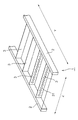
- FIG. 1 is a schematic cross-sectional view of a railway vehicle provided with a frame structure according to the present invention. It is a schematic perspective view which shows a side beam and a horizontal beam.
- FIG. 3 is a sectional view taken along line III-III in FIG. 1. It is an enlarged view of the structure floor part without a cross beam in FIG.
- FIG. 4 is an enlarged view of a cross beam portion in FIG. 3 where an underfloor device cannot be suspended.
- FIG. 4 is an enlarged view of a cross beam portion in FIG. 3 where an underfloor device is suspended.
- It is a front view of the cross beam of the state covered with the 2nd heat insulating material.
- FIG. 10 is a schematic front view of a cross beam showing the state before the underfloor fire in the underframe structure of FIG. 9.
- FIG. 9 is a schematic front view of the cross beam which shows the state after an underfloor fire. It is the figure which looked at the metal plate which covers the lower surface of a 1st heat insulating material from the downward direction.
- FIG. 13 is a sectional view taken along line XIII-XIII in FIG. 12.
- FIG. 14 is a partially enlarged view of FIG. 13.
- FIG. 13 is a sectional view taken along the line XV-XV in FIG. 12.
- FIG. 16 is a partially enlarged view of FIG. 15. It is the graph which showed the temperature ratio of the structure floor temperature and the furnace temperature with respect to the thickness of a 1st heat insulating material.
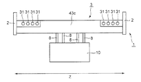
- FIG. 1 is a schematic sectional view of a railway vehicle provided with a frame structure according to the present invention.
- a frame 1 is provided at the lowermost part of the vehicle structure of the railway vehicle.
- the underframe 1 has a pair of side beams 2 arranged in the rail direction, that is, the vehicle longitudinal direction (Y direction), and the pair of side beams 2 in the sleeper direction, that is, the vehicle width direction (Z direction).
- FIG. 2 is a schematic perspective view showing the side beam 2 and the lateral beam 3.
- the horizontal beams 3 are provided at a pitch of 600 mm to 1000 mm in the Y direction.
- the horizontal beam 3 is provided with a plurality of pipe holes 31 arranged in parallel in the Z direction through which electric wires, air pipes, etc. (hereinafter, simply referred to as “electric pipes”) electric pipes and the like are inserted.
- a structural floor 4 as an airtight floor is provided on the underframe 1, and a plurality of floor receiving members 5 extending in the Y direction are erected on the structural floor 4 at intervals in the Z direction. .
- the floor receiving member 5 is configured to support the passenger compartment floor 6 constituting the floor of the passenger cabin S above the structural floor 4 at a predetermined interval.
- a seat 7 on which passengers sit is provided on the cabin floor 6.
- FIG. 3 is a cross-sectional view taken along the line III-III in FIG.
- the cross section of the cross beam 3 has a substantially I shape.
- a rectangular suspension groove 3a having a narrow lower end opening is formed integrally with the lower portion of the horizontal beam 3, and the heads of a plurality of suspension bolts 8 are inserted into the suspension groove 3a.
- the underfloor device 10 is supported by the suspension bolt 8 and the nut 8a via the bracket 9.
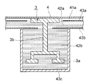
- FIG. 4 is an enlarged view of the structure floor 4 portion without the cross beam 3 in FIG. 3.
- a first heat insulating material 42a is provided below the structural floor 4 via a space (air layer 41a).
- the upper surface of the first heat insulating material 42a is covered with a second metal plate 43a, and the lower surface of the first heat insulating material 42a is covered with a first metal plate 43b.
- the first heat insulating material 42a is preferably made of glass fiber, ceramic fiber containing alumina fiber or the like.
- the second metal plate 43a and the first metal plate 43b are preferably stainless steel.
- the outer surfaces of the second metal plate 43a and the first metal plate 43b are preferably subjected to surface finishing such as polishing.
- the vertical thickness D1 of the air layer 41a is smaller than the vertical thickness D2 of the first heat insulating material 42a. Specifically, the thickness D1 is about 1/3 of the thickness D2.
- FIG. 5 is an enlarged view of the cross beam 3 portion in FIG. 3 where the underfloor device 10 is not suspended.
- a part below and at least the side of the cross beam 3, that is, the web 3b and the suspension groove 3a of the cross beam 3 are covered with the second heat insulating material 42b, and the outer surface of the second heat insulating material 42b has a U-shaped cross section.
- 3 metal plates 43c are covered.
- the upper surface of the horizontal beam 3 is attached to the structural floor 4, and the upper side of the horizontal beam 3 is covered with the air layer 41a or the first heat insulating material 42a.
- the third metal plate 43c is supported by the cross beam 3 via the second heat insulating material 42b, and the first metal plate 43b and the third metal plate 43c are not in contact with each other.
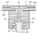
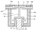
- FIG. 6 is an enlarged view of the horizontal beam 3 portion in FIG. 3 where the underfloor device 10 is suspended.
- the web 3b and the suspension groove 3a of the horizontal beam 3 are covered with a second heat insulating material 42b, and the outer surface of the second heat insulating material 42b is covered with a third metal plate 43c.
- the third metal plate 43c is supported by the suspension bolt 8, and the first metal plate 43b and the third metal plate 43c are not in contact with each other.
- a collar 32 is provided below the horizontal beam 3 and above the third metal plate 43 c, and the swing of the suspension bolt 8 is suppressed by the collar 32.
- FIG. 7 is a view showing a heat-resistant structure (modification) different from FIG. 6 of the horizontal beam 3 portion where the underfloor device 10 is suspended.
- the second heat insulating material 42b is formed in a U-shaped cross section, the outer side surface is covered with the third metal plate 43c, the inner side surface is covered with the fourth metal plate 43d, the inner fourth metal plate 43d and the cross beam 3
- An air layer 41b is provided therebetween.
- the third metal plate 43c and the fourth metal plate 43d covering the second heat insulating material 42b are supported by the suspension bolts 8, and the first metal plate 43b and the third metal plate 43c are not in contact with each other.
- the first metal plate 43b and the fourth metal plate 43d are not in contact with each other.
- FIG. 8 is a front view in the Y direction of the cross beam 3 in a state covered with the second heat insulating material 42b.
- the actual wire piping or the like is inserted at, for example, both ends in the Z direction except for the substantially central portion in the Z direction. Therefore, the horizontal beam 3 is covered with the second heat insulating material 42b covered with the third metal plate 43c except for several piping hole 31 portions at both ends in the Z direction.
- the second heat insulating material 42b is preferably the same as the first heat insulating material 42a.
- the third metal plate 43c and the fourth metal plate 43d are preferably the same as the second metal plate 43a and the first metal plate 43b.
- the underfloor device 10 is usually suspended at the center in the Z direction of the cross beam 3.
- the actual wire pipes or the like are inserted through, for example, both ends of the Z direction except the substantially central portion in the Z direction.
- the several piping holes 31 at both ends cannot be covered with the heat insulating material 42b because the wire piping or the like is inserted therethrough. Therefore, in the underfloor fire, the temperature of the pipe hole 31 portions at both ends of the cross beam 3 rises, and the cross beam 3 is easily deformed (flexed) downward. Therefore, in order to prevent the large deformation of the cross beam 3 that supports the underfloor device 10, it is necessary to reduce the load on the cross beam 3.
- FIG. 9 is a schematic perspective view of a frame structure that reduces the load burden on the cross beam 3.
- floor receiving members 5 extending in the Y direction are provided with an interval in the Z direction.
- the floor receiving member 5a provided at the substantially central portion in the Z direction excluding both ends in the Z direction is welded and fixed to the structural floor 4 over the entire length in the Y direction of the floor receiving member 5a.
- FIG. 10 and FIG. 11 are schematic front views of the cross beam 3 showing the state before the under-floor fire and after the under-floor fire in the frame structure of FIG. 9, respectively.
- the 3rd metal plate 43c which covers the 2nd heat insulating material 42b is deleted.
- the underfloor device 10 is suspended by a suspension bolt 8 at the center in the Z direction of the cross beam 3.
- the horizontal beam 3 is covered with the second heat insulating material 42 b except for the pipe hole 31 portions at both ends in the Z direction of the horizontal beam 3.
- the upper part of the horizontal beam 3 is attached to the structural floor 4, and the floor receiving member 5 is attached to the upper part of the structural floor 4 so as to connect the horizontal beams 3.
- the floor receiving member 5a at the substantially central portion in the Z direction on which the underfloor device 10 is suspended is fixed to the structural floor 4 over the entire length in the Y direction of the floor receiving member 5a.
- the floor receiving member 5a may be fixed to the structural floor 4 by welding, or the floor receiving member 5a and the structural floor 4 may be integrally formed. Therefore, as shown in FIG. 9, the floor receiving member 5 a can bear a part of the load G of the underfloor equipment 10. That is, a part of the load G of the underfloor device 10 is transmitted through the floor receiving member 5a in the F1 direction and the F2 direction parallel to the Y direction.
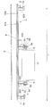
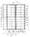
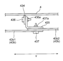
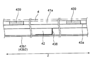
- FIG. 12 is a view of the first metal plate 43b covering the lower surface of the first heat insulating material 42a as viewed from below.
- 13 is a sectional view taken along the line XIII-XIII in FIG. 12
- FIG. 14 is a partially enlarged view of FIG. 13
- FIG. 15 is a sectional view taken along the line XV-XV in FIG. is there.
- the first metal plate 43b has two first metal plates 43b1 and 43b2 at the approximate center in the Y direction between the transverse beams 3 in the Y direction. It is constituted by combining.
- a plate-shaped first plate member 432 is attached to the upper portion of the cross beam 3 by welding, and a first support having a Z shape as viewed in the Z direction is provided at the end of the first metal plate 43b1 and the first metal plate 43b2 on the side of the horizontal beam 3.
- a member 433 is attached by welding.
- the end of the first support member 433 is inserted into the gap between the cross beam 3 and the first plate member 432 and placed on the first plate member 432, whereby the first metal plate 43 b 1 and the first metal plate 43 b 1 Each end of one metal plate 43b2 is supported by the cross beam 3.
- the first metal plate 43b1 and the first metal plate 43b2 are in direct contact with the flame. Attached to.
- the first metal plate 43 b 1 and the first metal plate 43 b 2 extend toward the cross beam 3 below the first plate member 432. With such a configuration, the first plate member 432 can be prevented from coming into direct contact with the flame.
- a plurality of first plate members 432 are provided at intervals in the Z direction.
- the contact area between the first plate member 432 and the cross beam 3 is reduced.
- the first metal plate 43b1 The amount of heat transfer from 43b2 to the cross beam 3 is reduced. Therefore, the temperature rise of the cross beam 3 can be reduced.
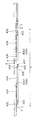
- FIG. 14 shows details of the connecting portion between the first metal plate 43b1 and the first metal plate 43b2.
- a second plate member 434 extending in a substantially vertical direction from the structural floor 4 is attached by welding to a substantially central portion in the Y direction between the cross beams 3 below the structural floor 4.
- the second plate member 434 and the second support member 435 that is L-shaped when viewed in the Z direction are fastened by a bolt 436 and a nut 436a.
- the second support member 435, the first metal plate 43b1, and the first metal plate 43b2 are fastened by bolts 437 and nuts 437a.
- a portion of the second support member 435 that is fastened together with the second plate member by the bolt 436 and the nut 436a is referred to as a first fastened portion
- the first metal plate 43b1 and the first metal are fastened by the bolt 437 and the nut 437a.
- the portion fastened together with the plate 43b2 is referred to as a second fastened portion.
- the second plate member 434 is substantially L-shaped, but the shape is not limited thereto, and may be fastened to the second plate member 434 and the first metal plates 43b1 and 43b2.
- each of the divided first metal plates 43b1 and 43b2 is inserted between the cross beam 3 and the first plate member 432, and the other end is bolt 436 via the second support member 435. And bolts 437 to the structural floor 4. Therefore, for example, even if the structural floor 4 is an aluminum alloy and the first metal plate 43b is stainless steel, that is, even if the structural floor 4 and the first metal plate 43b are made of different materials, the above mounting structure is adopted. Thus, the first metal plate 43b can be supported on the structural floor 4.
- the first metal plate 43b is divided into two parts, a first metal plate 43b1 and a first metal plate 43b2. Further, the first metal plates 43b1, 43b2 are further divided.
- a stiffener 438 having an L-shaped cross section to the upper surface of the first metal plates 43b1 and 43b2 by welding as shown in FIG.
- the stiffener 438 extends in the Y direction, and a plurality of stiffeners 438 are provided at intervals in the Z direction.
- a third support member 439 that supports the structural floor 4 is provided on the upper surface of the second metal plate 43a that is below the structural floor 4 and covers the upper surface of the first heat insulating material 42a.
- a plurality of third support members 439 are provided at intervals in the Z direction and the Y direction.
- the floor receiving member 5a Since the floor receiving member 5a is welded and fixed to the structural floor 4 over the entire length in the Y direction of the floor receiving member 5a, the floor receiving member 5a is a part of the load G of the underfloor device 10. Can be received. Therefore, even when the temperature at both ends of the horizontal beam 3 rises due to the underfloor fire and the horizontal beam 3 is likely to be deformed downward, a part of the load G of the underfloor device 10 is distributed to the floor receiving member 5a. Since the load which 3 receives becomes small, the deformation amount to the downward direction of the cross beam 3 can be reduced. Further, by reducing the amount of deformation of the horizontal beam 3 downward, it is possible to reduce the amount of deformation of the structural floor 4 and the cabin floor 6 downward.
- the vertical thickness (D1 + D2) that combines the air layer 41a and the first heat insulating material 42a while maintaining the heat insulating effect. ) can be shortened. As a result, the heat insulating structure below the structural floor 4 can be reduced, and the large underfloor device 10 can be attached.
- heat transfer forms are classified into heat conduction, heat transfer, and heat radiation (radiation), and heat conduction and radiation are main in a vehicle under-floor fire.
- radiation heat conduction and radiation
- the relationship between heat conduction and radiation differs depending on the temperature. At high temperatures (500 ° C. or higher), radiation is more dominant than heat conduction, and at low temperatures (500 ° C. or lower), heat conduction is more dominant than radiation. It becomes.
- the air layer 41a and the first heat insulating material 42a the heat conductivity of the air layer 41a is lower than that of the first heat insulating material 42a.
- the performance of blocking radiation is higher in the first heat insulating material 42a than in the air layer 41a.
- the lower temperature is higher and the upper temperature is lower. Therefore, the first heat insulating material 42a having high performance for blocking radiation is disposed below, and the air layer 41a having low thermal conductivity is disposed above.
- the vertical thickness (hereinafter referred to as “thickness”) of the air layer 41a and the first heat insulating material 42a can be made the thinnest. If the temperature of the flame is about 1000 ° C., the temperature of the lower surface of the first heat insulating material 42a is about 800 ° C. Here, the temperature of the lower surface of the air layer 41a is set to about 500 ° C.
- the thickness D1 of the layer 41a is preferably smaller than the thickness D2 of the first heat insulating material 42a. Furthermore, the thickness D1 of the air layer 41a is preferably about 1/3 of the thickness D2 of the first heat insulating material 42a.
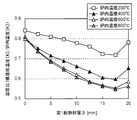
- the thickness D1 of the air layer 41a and the thickness D2 of the first heat insulating material 42a shows the structure floor 4 temperature and the furnace temperature (with respect to the thickness of the first heat insulating material 42a) when the sum of the thickness D1 of the air layer 41a and the thickness D2 of the first heat insulating material 42a is 20 mm. It is the graph which showed temperature ratio with (corresponding to the temperature of underfloor fire). From FIG. 17, for example, if the sum of the thickness D1 of the air layer 41a and the thickness D2 of the first heat insulating material 42a is about 20 mm, the thickness D1 of the air layer 41a is about 2.5 to 5 mm.
- the thickness D2 of the heat insulating material 42a is preferably about 17.5 to 15 mm.
- the first metal plate 43b is provided on the lower surface of the first heat insulating material 42a, the first heat insulating material 42a can be protected from a flame in an underfloor fire. Moreover, since the 1st heat insulating material 42a can be supported by the 1st metal plate 43b, it is not necessary to provide the special member for supporting the 1st heat insulating material 42a.
- the 2nd heat insulating material 42b Since the 2nd heat insulating material 42b is covered with the 3rd metal plate 43c, the 2nd heat insulating material 42b can be protected from the flame in an underfloor fire. Further, since the second heat insulating material can be supported by the third metal plate 43c and the fourth metal plate 43d, it is not necessary to provide a special member for supporting the second heat insulating material 42b.
- the amount of downward bending of the first metal plate 43b can be reduced.
- the first metal plate 43b is inserted into the gap between the cross beam 3 and the first plate member 432, and is placed on and supported by the first plate member 432. 4 is fastened with bolts 436 and 437 through a second support member 435. Therefore, different materials can be used for the cross beam 3, the structural floor 4, and the first metal plate 43b.
- the horizontal beam 3 and the structural floor 4 can be made of a light aluminum alloy
- the first metal plate 43b can be made of stainless steel having high fire resistance.
- the third support member 439 Since the third support member 439 is provided on the upper surface of the second metal plate 43a, the third support member 439 supports the structural floor 4 and reduces the amount of bending downward of the structural floor 4. be able to.
- the side beam 2 is preferably covered with a heat insulating material, and further preferably covered with a heat insulating material via an air layer.
- the floor receiving member 5a at the substantially central portion in the Z direction in which the underfloor device 10 is suspended is welded and fixed to the structural floor 4 over the entire length in the Y direction of the floor receiving member 5a.
- all the floor receiving members 5 may be fixed to the structural floor 4 by welding over the entire length of the floor receiving member 5 in the Y direction.
- the floor receiving member 5a is welded and fixed to the structural floor 4.
- the fixing method is not limited to welding, and the floor 4 is attached to the structural floor 4 so as to be able to bear a part of the load of the underfloor device 10. It only has to be attached.
- the floor receiving member 5a may be integrally formed with the structural floor 4, the floor receiving member 5a may be fastened to the structural floor 4 with bolts and nuts, or separately from the floor receiving member 5a.
- the floor receiving member 5a may be attached to the structural floor 4 via the connecting member.
- the pipe holes 31 are provided at both ends in the Z direction of the cross beam 3. However, the pipe holes 31 are located in the horizontal beam 3 and the floor receiving member 5a at the substantially central part in the Z direction where the underfloor device 10 is suspended. It suffices if it is provided in a range that does not correspond to a position immediately below.
- a railcar frame structure that can reduce the amount of deformation of a transverse beam that supports the underfloor equipment can be provided, and thus has high industrial utility value.
Landscapes
- Engineering & Computer Science (AREA)
- Mechanical Engineering (AREA)
- Life Sciences & Earth Sciences (AREA)
- Wood Science & Technology (AREA)
- Building Environments (AREA)
Priority Applications (3)
| Application Number | Priority Date | Filing Date | Title |
|---|---|---|---|
| EP11839630.8A EP2639133A4 (en) | 2010-11-08 | 2011-11-04 | Underframe structure of railroad vehicle |
| US13/882,887 US9108649B2 (en) | 2010-11-08 | 2011-11-04 | Underframe structure of railcar |
| CN201180053578.8A CN103201156B (zh) | 2010-11-08 | 2011-11-04 | 铁路车辆的底架结构 |
Applications Claiming Priority (2)
| Application Number | Priority Date | Filing Date | Title |
|---|---|---|---|
| JP2010249904A JP5583553B2 (ja) | 2010-11-08 | 2010-11-08 | 鉄道車両の台枠構造 |
| JP2010-249904 | 2010-11-08 |
Publications (1)
| Publication Number | Publication Date |
|---|---|
| WO2012063721A1 true WO2012063721A1 (ja) | 2012-05-18 |
Family
ID=46050869
Family Applications (1)
| Application Number | Title | Priority Date | Filing Date |
|---|---|---|---|
| PCT/JP2011/075378 Ceased WO2012063721A1 (ja) | 2010-11-08 | 2011-11-04 | 鉄道車両の台枠構造 |
Country Status (5)
| Country | Link |
|---|---|
| US (1) | US9108649B2 (enExample) |
| EP (1) | EP2639133A4 (enExample) |
| JP (1) | JP5583553B2 (enExample) |
| CN (1) | CN103201156B (enExample) |
| WO (1) | WO2012063721A1 (enExample) |
Cited By (3)
| Publication number | Priority date | Publication date | Assignee | Title |
|---|---|---|---|---|
| WO2015071926A1 (ja) | 2013-11-12 | 2015-05-21 | 川崎重工業株式会社 | 鉄道車両 |
| CN107406085A (zh) * | 2015-03-20 | 2017-11-28 | 川崎重工业株式会社 | 铁道车辆 |
| US11161528B2 (en) | 2017-12-15 | 2021-11-02 | Alstom Transport Technologies | Railway vehicle coach |
Families Citing this family (12)
| Publication number | Priority date | Publication date | Assignee | Title |
|---|---|---|---|---|
| US9067606B2 (en) * | 2011-02-17 | 2015-06-30 | East Japan Railway Company | Railcar |
| DE102011011633A1 (de) * | 2011-02-17 | 2012-08-23 | Siemens Aktiengesellschaft | Abstützvorrichtung für einen Schienenfahrzeug-Fußboden |
| CA2806886C (en) * | 2013-02-20 | 2015-04-28 | Bombardier Transportation Gmbh | Heat resistant floor assembly for a rail vehicle |
| JP6157731B2 (ja) * | 2014-05-22 | 2017-07-05 | 三菱電機株式会社 | Atcアンテナ装置、atc信号伝送装置及び車両 |
| US10549764B2 (en) * | 2015-02-27 | 2020-02-04 | Kawasaki Jukogyo Kabushiki Kaisha | Attaching metal fitting, attaching unit, and railcar |
| JP6510449B2 (ja) * | 2015-04-24 | 2019-05-08 | 株式会社日立製作所 | 鉄道車両の製造方法 |
| CN104787062B (zh) * | 2015-05-06 | 2018-02-02 | 中车青岛四方机车车辆股份有限公司 | 一种铁路车辆用高压设备箱 |
| JP6359170B2 (ja) | 2015-08-31 | 2018-07-18 | 日本車輌製造株式会社 | 鉄道車両 |
| WO2017037852A1 (ja) | 2015-08-31 | 2017-03-09 | 日本車輌製造株式会社 | 鉄道車両 |
| CN106365022A (zh) * | 2016-08-31 | 2017-02-01 | 中车青岛四方机车车辆股份有限公司 | 吊挂装置及具有其的列车 |
| CN113306587B (zh) * | 2021-06-21 | 2022-12-09 | 中车株洲电力机车有限公司 | 一种轨道车辆底架结构 |
| CN114454906B (zh) * | 2022-02-25 | 2023-09-19 | 中车青岛四方机车车辆股份有限公司 | 一种轨道车辆车下管路布置结构、底架及轨道车辆 |
Citations (13)
| Publication number | Priority date | Publication date | Assignee | Title |
|---|---|---|---|---|
| JPS55132363A (en) * | 1979-03-28 | 1980-10-15 | Hitachi Ltd | Structure of floor of railway rolling stock |
| JPS59153654A (ja) * | 1983-02-23 | 1984-09-01 | 株式会社日立製作所 | 車両の床構造 |
| JPS59164262A (ja) * | 1983-03-04 | 1984-09-17 | 株式会社日立製作所 | 鉄道車両の床下断熱材押え |
| JPS60234065A (ja) * | 1984-05-04 | 1985-11-20 | 株式会社日立製作所 | 鉄道車両の床構造 |
| JPS6264667A (ja) * | 1985-09-18 | 1987-03-23 | 株式会社日立製作所 | 鉄道車両用台枠構造 |
| JPS636970U (enExample) * | 1986-06-27 | 1988-01-18 | ||
| JPS6478970A (en) * | 1987-09-18 | 1989-03-24 | Railway Technical Res Inst | Base frame for rolling stock |
| JPH0275373U (enExample) * | 1988-11-30 | 1990-06-08 | ||
| JPH0874346A (ja) * | 1994-09-05 | 1996-03-19 | Asahi Chem Ind Co Ltd | 断熱性複合パネル |
| JP2000203423A (ja) * | 1999-01-13 | 2000-07-25 | Hitachi Ltd | 高速鉄道車両用構体 |
| JP2007191016A (ja) * | 2006-01-18 | 2007-08-02 | Hitachi Ltd | 軌条車両の床構造 |
| JP2007308042A (ja) | 2006-05-19 | 2007-11-29 | West Japan Railway Co | 鉄道車両の防振ゴム支持構造およびその防振ゴムのばね定数の設定方法 |
| JP2008247228A (ja) * | 2007-03-30 | 2008-10-16 | Hitachi Ltd | 軌条車両 |
Family Cites Families (9)
| Publication number | Priority date | Publication date | Assignee | Title |
|---|---|---|---|---|
| US730251A (en) * | 1902-12-01 | 1903-06-09 | George Gibbs | Electric-motor car and system of mounting and wiring electrical apparatus thereon. |
| US1244826A (en) * | 1916-09-13 | 1917-10-30 | Charles H Anderson | Underframe for cars. |
| US2294357A (en) * | 1940-05-18 | 1942-08-25 | Budd Edward G Mfg Co | Vehicle body construction |
| US2801597A (en) * | 1953-05-13 | 1957-08-06 | Acf Ind Inc | Underframe for railway cars |
| US4645258A (en) * | 1984-10-03 | 1987-02-24 | Hitachi, Ltd. | Underframe construction for railway vehicle |
| JPS62189251A (ja) * | 1986-02-13 | 1987-08-19 | 川崎重工業株式会社 | 床構造 |
| US4966082A (en) * | 1987-10-21 | 1990-10-30 | Hitachi, Ltd. | Construction and a manufacturing method of underframe for a rolling stock |
| US6722288B2 (en) * | 2001-05-02 | 2004-04-20 | Trn Business Trust | Railway box car with lower center of gravity |
| FR2928330B1 (fr) * | 2008-03-10 | 2012-05-11 | Alstom Transport Sa | Chassis de vehicule ferroviaire pourvu de panneaux d'isolation thermique |
-
2010
- 2010-11-08 JP JP2010249904A patent/JP5583553B2/ja not_active Expired - Fee Related
-
2011
- 2011-11-04 WO PCT/JP2011/075378 patent/WO2012063721A1/ja not_active Ceased
- 2011-11-04 US US13/882,887 patent/US9108649B2/en not_active Expired - Fee Related
- 2011-11-04 CN CN201180053578.8A patent/CN103201156B/zh not_active Expired - Fee Related
- 2011-11-04 EP EP11839630.8A patent/EP2639133A4/en not_active Withdrawn
Patent Citations (13)
| Publication number | Priority date | Publication date | Assignee | Title |
|---|---|---|---|---|
| JPS55132363A (en) * | 1979-03-28 | 1980-10-15 | Hitachi Ltd | Structure of floor of railway rolling stock |
| JPS59153654A (ja) * | 1983-02-23 | 1984-09-01 | 株式会社日立製作所 | 車両の床構造 |
| JPS59164262A (ja) * | 1983-03-04 | 1984-09-17 | 株式会社日立製作所 | 鉄道車両の床下断熱材押え |
| JPS60234065A (ja) * | 1984-05-04 | 1985-11-20 | 株式会社日立製作所 | 鉄道車両の床構造 |
| JPS6264667A (ja) * | 1985-09-18 | 1987-03-23 | 株式会社日立製作所 | 鉄道車両用台枠構造 |
| JPS636970U (enExample) * | 1986-06-27 | 1988-01-18 | ||
| JPS6478970A (en) * | 1987-09-18 | 1989-03-24 | Railway Technical Res Inst | Base frame for rolling stock |
| JPH0275373U (enExample) * | 1988-11-30 | 1990-06-08 | ||
| JPH0874346A (ja) * | 1994-09-05 | 1996-03-19 | Asahi Chem Ind Co Ltd | 断熱性複合パネル |
| JP2000203423A (ja) * | 1999-01-13 | 2000-07-25 | Hitachi Ltd | 高速鉄道車両用構体 |
| JP2007191016A (ja) * | 2006-01-18 | 2007-08-02 | Hitachi Ltd | 軌条車両の床構造 |
| JP2007308042A (ja) | 2006-05-19 | 2007-11-29 | West Japan Railway Co | 鉄道車両の防振ゴム支持構造およびその防振ゴムのばね定数の設定方法 |
| JP2008247228A (ja) * | 2007-03-30 | 2008-10-16 | Hitachi Ltd | 軌条車両 |
Non-Patent Citations (1)
| Title |
|---|
| See also references of EP2639133A4 |
Cited By (6)
| Publication number | Priority date | Publication date | Assignee | Title |
|---|---|---|---|---|
| WO2015071926A1 (ja) | 2013-11-12 | 2015-05-21 | 川崎重工業株式会社 | 鉄道車両 |
| KR20160074636A (ko) | 2013-11-12 | 2016-06-28 | 카와사키 주코교 카부시키 카이샤 | 철도 차량 |
| US10029709B2 (en) | 2013-11-12 | 2018-07-24 | Kawasaki Jukogyo Kabushiki Kaisha | Railcar |
| CN107406085A (zh) * | 2015-03-20 | 2017-11-28 | 川崎重工业株式会社 | 铁道车辆 |
| CN107406085B (zh) * | 2015-03-20 | 2019-04-16 | 川崎重工业株式会社 | 铁道车辆 |
| US11161528B2 (en) | 2017-12-15 | 2021-11-02 | Alstom Transport Technologies | Railway vehicle coach |
Also Published As
| Publication number | Publication date |
|---|---|
| CN103201156B (zh) | 2015-10-14 |
| EP2639133A1 (en) | 2013-09-18 |
| JP5583553B2 (ja) | 2014-09-03 |
| US9108649B2 (en) | 2015-08-18 |
| EP2639133A4 (en) | 2017-12-06 |
| US20130220169A1 (en) | 2013-08-29 |
| JP2012101597A (ja) | 2012-05-31 |
| CN103201156A (zh) | 2013-07-10 |
Similar Documents
| Publication | Publication Date | Title |
|---|---|---|
| JP5583553B2 (ja) | 鉄道車両の台枠構造 | |
| JP5697953B2 (ja) | 鉄道車両の床構造 | |
| US10029709B2 (en) | Railcar | |
| JP6522111B2 (ja) | 鉄道車両 | |
| JP2012101597A5 (enExample) | ||
| JP2012101596A5 (enExample) | ||
| WO2013157464A1 (ja) | 軌条車両構体 | |
| JP2010173628A (ja) | 車体構造 | |
| WO2012172925A1 (ja) | 配線・配管モジュールを備える鉄道車両の車体構造及びその製作方法 | |
| JP2009255641A (ja) | 車体構造 | |
| WO2013145660A1 (ja) | 鉄道車両の床構造及びそれを備えた鉄道車両 | |
| CN109109892B (zh) | 轨道车辆的底架组件及轨道车辆 | |
| HK1186713A (en) | Floor structure of railroad vehicle | |
| HK1186712A (en) | Underframe structure of railroad vehicle | |
| US20150210297A1 (en) | Multifunctional fastening profile | |
| JP2009196531A (ja) | リニアモータ車両の床構造 | |
| JP4640959B2 (ja) | 軌条車両の床構造 | |
| KR101234106B1 (ko) | 철도차량용 언더 프레임 | |
| JP2013071648A (ja) | 鉄道車両構体 | |
| JP2012051495A (ja) | 鉄道車両構体 | |
| JPH057221B2 (enExample) |
Legal Events
| Date | Code | Title | Description |
|---|---|---|---|
| 121 | Ep: the epo has been informed by wipo that ep was designated in this application |
Ref document number: 11839630 Country of ref document: EP Kind code of ref document: A1 |
|
| WWE | Wipo information: entry into national phase |
Ref document number: 13882887 Country of ref document: US |
|
| NENP | Non-entry into the national phase |
Ref country code: DE |
|
| WWE | Wipo information: entry into national phase |
Ref document number: 2011839630 Country of ref document: EP |