WO2012063684A1 - Machine dynamoélectrique - Google Patents
Machine dynamoélectrique Download PDFInfo
- Publication number
- WO2012063684A1 WO2012063684A1 PCT/JP2011/075194 JP2011075194W WO2012063684A1 WO 2012063684 A1 WO2012063684 A1 WO 2012063684A1 JP 2011075194 W JP2011075194 W JP 2011075194W WO 2012063684 A1 WO2012063684 A1 WO 2012063684A1
- Authority
- WO
- WIPO (PCT)
- Prior art keywords
- stator core
- rotating electrical
- electrical machine
- stator
- housing
- Prior art date
Links
Images


Classifications
-
- H—ELECTRICITY
- H02—GENERATION; CONVERSION OR DISTRIBUTION OF ELECTRIC POWER
- H02K—DYNAMO-ELECTRIC MACHINES
- H02K1/00—Details of the magnetic circuit
- H02K1/06—Details of the magnetic circuit characterised by the shape, form or construction
- H02K1/12—Stationary parts of the magnetic circuit
- H02K1/18—Means for mounting or fastening magnetic stationary parts on to, or to, the stator structures
- H02K1/185—Means for mounting or fastening magnetic stationary parts on to, or to, the stator structures to outer stators
-
- H—ELECTRICITY
- H02—GENERATION; CONVERSION OR DISTRIBUTION OF ELECTRIC POWER
- H02K—DYNAMO-ELECTRIC MACHINES
- H02K5/00—Casings; Enclosures; Supports
- H02K5/04—Casings or enclosures characterised by the shape, form or construction thereof
-
- H—ELECTRICITY
- H02—GENERATION; CONVERSION OR DISTRIBUTION OF ELECTRIC POWER
- H02K—DYNAMO-ELECTRIC MACHINES
- H02K1/00—Details of the magnetic circuit
- H02K1/06—Details of the magnetic circuit characterised by the shape, form or construction
- H02K1/12—Stationary parts of the magnetic circuit
- H02K1/16—Stator cores with slots for windings
-
- H—ELECTRICITY
- H02—GENERATION; CONVERSION OR DISTRIBUTION OF ELECTRIC POWER
- H02K—DYNAMO-ELECTRIC MACHINES
- H02K2201/00—Specific aspects not provided for in the other groups of this subclass relating to the magnetic circuits
- H02K2201/09—Magnetic cores comprising laminations characterised by being fastened by caulking
Definitions
- the present invention relates to a rotating electrical machine, and more particularly to a rotating electrical machine that generates torque for driving a vehicle or generates electric power during braking.
- the rotating electrical machine includes a stator and a rotor, and the stator has a stator core in which a large number of slots are formed.
- the stator core is usually integrated by welding a predetermined number of electromagnetic steel sheets of about 0.05 to 1.0 mm and welding a predetermined position on the outer periphery of the electromagnetic steel sheet. (See Patent Document 1).
- a coil is wound around the stator core produced in this way.
- the rotating electrical machine generates a rotating magnetic field by supplying AC power to the coil, and rotates the rotor by the rotating magnetic field.
- the rotating electrical machine converts mechanical energy applied to the rotor into electrical energy and outputs AC power from the coil.
- the rotating electrical machine operates as an electric motor or a generator.
- a rotating electrical machine that includes a stator, a rotor that is rotatably provided inside the stator, and a housing that holds the stator by shrink fitting or press fitting.
- the rotating electrical machine may be fixed at an appropriate position of the automobile by a flange provided on one end surface of the housing.
- compressive stress is concentrated on the portion of the stator core corresponding to the flange of the housing, and the magnetic steel sheet of the portion where the stress is concentrated is deformed so as to wave (extend in the axial direction).
- a rotating electrical machine includes a cylindrical housing having a plurality of flanges attached to a case, and a stator having a cylindrical stator core fixed to the housing by shrink fitting or press fitting. And a rotor disposed rotatably in the stator, and the stator iron core is formed by laminating a plurality of steel plates, and a reinforcing portion for suppressing deformation of the steel plates is provided in the stator iron core.
- the reinforcing portion is preferably a welded portion provided in parallel to the axial direction of the stator core.
- the reinforcing portion is preferably a caulking portion for laminating and fixing the steel plates.
- the welded portion is provided on the outer peripheral portion and / or the inner peripheral portion of the stator core.
- the reinforcing portion is preferably disposed on the central axis of the teeth of the stator core.
- the welding groove is provided on the outer peripheral portion on the central axis of all teeth of the stator core, and the flange of the housing It is preferable that a welded portion is provided in the weld groove arranged corresponding to the above.
- the stator core is an integral core, and the stator core includes a stator core.
- a plurality of slots parallel to the axial direction are formed, and in the slots, a segment type coil in which a plurality of segment conductors are connected to each other, and insulation for insulating between the segment conductors and between the slot and the segment conductors. It is preferable that paper is disposed.
- the plurality of flanges project radially outward at the peripheral edge of the one end surface of the cylindrical housing. It is preferable.
- FIG. 1 It is a mimetic diagram showing the whole rotary electric machine composition concerning an embodiment of the present invention. It is a perspective view which shows the stator and housing of a rotary electric machine which concern on the 1st Embodiment of this invention. It is a perspective view which shows the stator core of the rotary electric machine which concerns on the 1st Embodiment of this invention. It is a perspective view which shows the electromagnetic steel plate which comprises the stator core which concerns on the 1st Embodiment of this invention. It is a perspective view which shows the stator coil for three phases wound around a stator core. It is a perspective view which shows the U-phase stator coil wound around a stator core.
- FIG.9 (a) is a schematic diagram which shows the cross section of a rotor and a stator
- FIG.9 (b) is the A section enlarged schematic diagram of Fig.9 (a).
- FIG. 1 It is a schematic diagram which shows the cross section of the crimping part which carries out the lamination
- the rotating electrical machine according to the present embodiment is a rotating electrical machine that is suitable for use in driving an automobile.
- the so-called electric vehicles using a rotating electric machine include a hybrid type electric vehicle (HEV) having both an engine and a rotating electric machine, and a pure electric vehicle (EV) that runs only by the rotating electric machine without using an engine.
- HEV hybrid type electric vehicle
- EV pure electric vehicle
- the rotating electrical machine described below can be used for both types, the description will be made based on the rotating electrical machine typically used for a hybrid type electric vehicle.
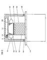
- FIG. 1 is a schematic diagram showing an overall configuration of a rotating electrical machine 100 according to an embodiment of the present invention.
- the inside of the rotating electrical machine 100 is shown by making a part of the rotating electrical machine 100 into a cross section.
- the rotating electrical machine 100 is disposed inside the case 10 as shown in FIG.
- the rotating electrical machine 100 includes a housing 112, a stator 130 having a stator core 132 fixed to the housing 112, and a rotor 150 that is rotatably disposed in the stator 130.
- the case 10 includes an engine case and a transmission case.
- Rotating electric machine 100 is a three-phase synchronous motor with a built-in permanent magnet.
- the rotating electrical machine 100 operates as an electric motor that rotates the rotor 150 when a three-phase alternating current is supplied to the stator coil 138 wound around the stator core 132.
- the rotating electrical machine 100 When the rotating electrical machine 100 is driven by an engine, the rotating electrical machine 100 operates as a generator and outputs three-phase AC generated power. That is, the rotating electrical machine 100 has both a function as an electric motor that generates rotational torque based on electric energy and a function as a generator that generates electric power based on mechanical energy. Functions can be used selectively.
- the stator 130 fixed to the housing 112 is fixedly held in the case 10 by fastening a flange 115 provided on the housing 112 to the case 10 with a bolt 12.
- the rotor 150 is fixed to the shaft 118 supported by the bearings 14A and 14B of the case 10, and is rotatably held inside the stator core 132.
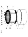
- FIG. 2 is a perspective view showing the housing 112 and the stator 130 of the rotating electrical machine 100 according to the first embodiment of the present invention.
- the housing 112 is formed into a cylindrical shape by drawing a steel plate (such as a high-tensile steel plate) having a thickness of about 2 to 5 mm.
- the housing 112 is provided with a plurality of flanges 115 attached to the case 10.
- the plurality of flanges 115 project outward in the radial direction at the periphery of one end surface of the cylindrical housing 112.
- the flange 115 is formed by cutting away portions other than the flange 115 at the end portion formed during drawing, and is integrated with the housing 112.
- the stator 130 has a cylindrical stator core 132 and a stator coil 138 attached to the stator core 132.
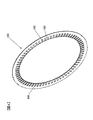
- FIG. 3 is a perspective view showing the stator core 132
- FIG. 4 is a perspective view showing the electromagnetic steel sheet 133 constituting the stator core 132.
- the stator core 132 is formed such that a plurality of slots 420 parallel to the axial direction of the stator core 132 are equally spaced in the circumferential direction.
- the number of slots 420 is, for example, 72 in the present embodiment, and the stator coils 138 described above are accommodated in the slots 420.
- the inner circumferential side of each slot 420 is an opening, and the circumferential width of this opening is substantially equal to or slightly smaller than the coil mounting portion of each slot 420 in which the stator coil 138 is mounted.
- Teeth 430 are formed between the slots 420, and each tooth 430 is integrated with an annular core back 440. That is, the stator core 132 is an integrated core in which the teeth 430 and the core back 440 are integrally formed.
- the teeth 430 serve to guide the rotating magnetic field generated by the stator coil 138 to the rotor 150 and generate a rotating torque in the rotor 150.
- the stator core 132 is formed by punching or etching a magnetic steel sheet 133 (see FIG. 4) having a thickness of about 0.05 to 1.0 mm, and laminating a plurality of formed annular magnetic steel sheets 133. It becomes.
- the stator core 132 is fitted and fixed to the inside of the cylindrical housing 112 by shrink fitting.
- the stator core 132 is arranged, and the housing 112 that has been heated in advance and expanded in inner diameter by thermal expansion is fitted into the stator core 132.
- the housing 112 is cooled to shrink the inner diameter, whereby the outer peripheral portion of the stator core 132 is tightened by the heat shrinkage.
- the inner diameter dimension of the housing 112 is set smaller than the outer diameter dimension of the stator core 132 by a predetermined value so that the stator core 132 does not idle with respect to the housing 112 due to a reaction caused by the torque of the rotor 150 during operation.
- the stator core 132 is firmly fixed in the housing 112 by shrink fitting.
- the difference between the outer diameter of the stator core 132 at normal temperature and the inner diameter of the housing 112 is referred to as a tightening allowance.
- the tightening allowance assuming the maximum torque of the rotating electrical machine 100, the housing 112 can have a predetermined tightening force.
- the stator core 132 is held.
- stator core 132 is not limited to being fitted and fixed by shrink fitting, but may be fixed to the housing 112 by press fitting.
- the stator core 132 in the present embodiment is provided with a welded portion 200 as a reinforcing portion as shown in FIG.
- the reinforcing portion connects the laminated electromagnetic steel plates 133 and suppresses deformation of the electromagnetic steel plates 133 due to the tightening force of the housing 112.
- the reinforcing part will be described later.
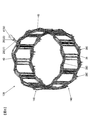
- FIG. 5 is a perspective view showing a stator coil 138 for three phases.
- FIGS. 6, 7 and 8 are perspective views showing a U-phase stator coil 138, a U1-phase stator coil 138 and a U2-phase stator coil 138 wound around the stator core 132, respectively.
- the stator coil 138 is wound in a distributed winding manner and connected in a star connection configuration.
- the distributed winding is a winding method in which the phase windings are wound around the stator core 132 so that the phase windings are housed in two slots 420 that are spaced apart from each other across the plurality of slots 420.
- distributed winding is adopted as the winding method, so that the formed magnetic flux distribution is closer to a sine wave than concentrated winding, and has a feature that reluctance torque is likely to be generated.
- this rotating electrical machine 100 has improved controllability using field-weakening control and reluctance torque, and can be used over a wide rotational speed range from a low rotational speed to a high rotational speed, and is suitable for an electric vehicle. Excellent motor characteristics can be obtained.
- the upper / lower coil may be shifted by one slot at a time, and short-pitch winding may be performed so that harmonic components can be suppressed.
- the stator coil 138 constitutes a three-phase star-connected phase coil, and the cross section may be round or rectangular. Since the cross-section of the stator coil 138 tends to improve efficiency by using the cross-section inside the slot 420 as effectively as possible and reducing the space in the slot, the quadrilateral cross-section of the stator coil 138 tends to increase. It is desirable in terms of efficiency improvement.
- the square shape of the cross section of the stator coil 138 may be a shape in which the circumferential direction of the stator core 132 is short and the radial direction is long, or conversely, the circumferential direction is long and the radial direction is short. It may be.
- the stator coil 138 has a rectangular wire in which the rectangular cross section of the stator coil 138 is long in the circumferential direction of the stator core 132 and short in the radial direction of the stator core 138 in each slot 420. It is used (see FIG. 9B).
- the rectangular wire has an outer periphery covered with an insulating film.
- the stator coil 138 is a segment type coil formed by connecting a plurality of U-shaped segment conductors 28 to each other.
- the segment conductor 28 has a central portion 28 ⁇ / b> C disposed at one coil end 140, and both end portions 28 ⁇ / b> E and 28 ⁇ / b> E are welded at the other coil end 140.
- the stator coil 138 includes six coils (U 1, U 2, V 1, V 2, W 1, W 2) as a whole (see FIG. 5) that are closely attached to the stator core 132. .
- the six coils constituting the stator coil 138 are arranged at appropriate intervals by the slot 420.
- one coil end 140 of the stator coil 138 has AC terminals 41 (U), 42 (V), which are coil conductors for input / output of the stator coils 138 of each of the UVW three phases. 43 (W) and the neutral point connection conductor 40 are drawn out.
- the AC terminals 41 (U), 42 (V), and 43 (W) for receiving the three-phase AC power are arranged in the axial direction of the stator core 132 from the coil end 140. It is arranged so as to protrude outward.
- the stator 130 is connected to a power converter (not shown) via AC terminals 41 (U), 42 (V), and 43 (W), so that AC power is supplied.
- Two neutral point connection conductors 40 arranged on both sides of the coil conductor for input / output are a U1 phase neutral wire that is the end of winding of the U1 phase, a V1 phase neutral wire that is the end of winding of the V1 phase, and W1. It consists of a W1 phase neutral wire that is the end of winding of the phase.
- Each neutral point connection conductor 40 has a structure in which three neutral wires are welded in advance, are epoxy-coated, and are directly wound around the top surface of the coil on the crown side.
- a jumper wire is arranged at the coil end 140, which is a portion of the stator coil 138 that protrudes outward in the axial direction from the stator core 132.
- This has the effect of reducing the overall size of the rotating electrical machine.
- the coil end 140 is orderly from the viewpoint of improving the reliability of the insulation characteristics. Since it is a direct oil cooling system in which cooling oil is directly applied to the coil end 140, when the coil end 140 is in order, the cooling oil is applied to the coil surface, so that the cooling performance is good.
- U, V, and W terminals are connected by resistance brazing using terminal parts for rectangular wires.
- the terminal parts are formed by punching a copper plate and extruding a plurality of projections with a diameter of 1 to 3 with punches from the back side of the copper plate so that the height is 0.1 mm to 0.2 mm. It is a projection system in which a copper plate and a brazing material are sandwiched between electrodes and energized while being pressurized.
- the contact portion between the copper plate and the brazing material generates heat locally, and the brazing material is melted and joined to the copper plate to be temporarily fixed. Since the brazing material is temporarily fixed by a plurality of projections, the brazing material is hardly affected by the tensile stress at the time of bending, and cracking and peeling of the brazing material can be prevented. In addition, you may use the clad material to which the brazing material has been attached beforehand. Alternatively, the terminal may be a terminal only with heat caulking. A temperature measuring sensor is enclosed by a tube such as a heat shrinkable tube and is brought into contact with a rectangular coil.
- the stator coil 138 has a structure in which the outer periphery of the conductor is covered with an insulating film, and the electrical insulation is maintained. In addition to the insulating film, the insulation voltage is maintained by the insulating paper 300 (see FIG. 2). This is preferable because the reliability can be further improved.
- the insulating paper 300 is disposed in the slot 420 and the coil end 140.
- the insulating paper 300 (so-called slot liner) disposed in the slot 420 is disposed between the segment conductors 28 inserted into the slot 420 and between the segment conductor 28 and the inner surface of the slot 420 (FIG. 9 ( b)), the dielectric strength between the segment conductors and between the segment conductor 28 and the inner surface of the slot 420 is improved.
- the slot liner shape is B-shaped for the purpose of reinforcing the insulation between the ground and the different phases as well as between the ground and different phases, and each coil is covered with a slot liner.
- the insulating paper 300 disposed at the coil end 140 is used by being annularly disposed between the segment conductors for interphase insulation and interconductor insulation at the coil end 140.
- the insulating paper 300 is an insulating sheet of heat-resistant polyamide paper, for example, and has a thickness of about 0.1 to 0.5 mm.
- the rectangular wire has a relatively wide coil interval, and high fluidity such as an insulating varnish flows down without adhering to the coil surface, so an insulator is used to positively adhere the varnish to the coil surface. Yes.
- the varnish can be permeated widely. Since cooling oil flows along the insulator, the coil end 140 can be effectively cooled.
- FIG. 9A is a schematic diagram showing cross sections of the rotor 150 and the stator 130.
- FIG. 9A the illustration of the stator coil 138 and the insulating paper 300 housed in the shaft 118 and the slot 420 is omitted to avoid complexity.
- FIG. 9B is an enlarged schematic diagram of a part A in FIG. 9A, and illustrates the stator coil 138 and the insulating paper 300 disposed in the slot 420.
- the rotor 150 includes a rotor core 152 and permanent magnets 154 held in magnet insertion holes formed in the rotor core 152.
- the rotor core 152 has a skew structure divided in the axial direction, and the magnet is divided in the axial direction. For example, the magnet is divided into two parts per pole and has a 12-pole V-shaped structure.
- the width of the magnet insertion hole in the circumferential direction is larger than the width of the permanent magnet 154 in the circumferential direction, and magnetic gaps 156 are formed on both sides of the permanent magnet 154.
- the magnetic gap 156 may be embedded with an adhesive, or may be solidified integrally with the permanent magnet 154 with a resin.
- -permanent magnet- Permanent magnet 154 forms a field pole of rotor 150.
- one magnetic pole is formed by one permanent magnet 154, but one magnetic pole may be formed by a plurality of permanent magnets. By increasing the number of permanent magnets for forming each magnetic pole, the magnetic flux density of each magnetic pole emitted from the permanent magnet is increased, and the magnet torque can be increased.
- the magnetization direction of the permanent magnet 154 is directed in the radial direction, and the direction of the magnetization direction is reversed for each field pole. That is, if the surface on the stator side of the permanent magnet 154 for forming a certain magnetic pole is magnetized to the N pole and the surface on the shaft side is magnetized to the S pole, the stator side of the permanent magnet 154 that forms the adjacent magnetic pole is assumed. The surface is magnetized so as to be the south pole and the shaft side surface is the north pole.
- the 12 permanent magnets 154 are magnetized so as to change the magnetization direction alternately for each magnetic pole at equal intervals in the circumferential direction, so that the rotor 150 forms 12 magnetic poles. ing.
- the permanent magnet 154 may be magnetized and then embedded in the magnet insertion hole of the rotor core 152, or the permanent magnet 154 may be inserted into the magnet insertion hole of the rotor core 152 before being magnetized, and then a strong magnetic field is applied to magnetize the permanent magnet 154. You may make it do.
- the magnetized permanent magnet 154 has a strong magnetic force. If the magnet is magnetized before the permanent magnet 154 is fixed to the rotor 150, a strong attractive force is generated between the permanent magnet 154 and the rotor core 152. This suction force prevents the work. There is a possibility that dust such as iron powder adheres to the permanent magnet 154 due to the strong attractive force. Therefore, in order to improve the productivity of the rotating electrical machine 100, it is desirable that the permanent magnet 154 is magnetized after being inserted into the magnet insertion hole of the rotor core 152.
- the permanent magnet 154 a neodymium-based or samarium-based sintered magnet, a ferrite magnet, a neodymium-based bonded magnet, or the like can be used.
- the residual magnetic flux density of the permanent magnet 154 is preferably about 0.4 to 1.3 T, and a neodymium magnet is more suitable.
- the auxiliary magnetic pole 160 is formed between the permanent magnets 154 forming the magnetic pole.
- the auxiliary magnetic pole 160 acts to reduce the magnetic resistance of the q-axis magnetic flux generated by the stator coil 138.
- the auxiliary magnetic pole 160 causes the reluctance torque to be generated because the magnetic resistance of the q-axis magnetic flux is much smaller than the magnetic resistance of the d-axis magnetic flux.
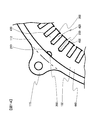
- FIG. 10 is a schematic plan view showing a state where the stator core 132 of the rotating electrical machine 100 according to the first embodiment of the present invention is fixed to the housing 112 by shrink fitting or press fitting.
- illustration of the stator coil 138 and the insulating paper 300 disposed inside the slot 420 is omitted.
- stator core 132 is fitted and fixed to the housing 112 by shrink fitting or press fitting.
- a compression stress is generated in the stator core 132 after the shrink-fitting or press-fitting due to the fastening force of the housing 112. This compressive stress is concentrated particularly on the portion of the housing 112 where the flange 115 abuts.
- the electromagnetic steel sheet 133 constituting the stator core 132 is deformed to have a shape corrugated in the axial direction.
- the insulating paper 300 disposed in the slot 420 and the insulating coating of the stator coil 138 are damaged, and the coil conductors and the coil conductors and the stator core 132 are separated. There is a risk of short-circuiting and reducing insulation.
- the stator core surface is deformed, the creeping distance between the stator core 132 and the coil conductor at the coil end 140 is shortened, and the coil conductor and the stator core 132 may be short-circuited.
- the tendency for the insulation properties to decrease becomes more prominent as the space factor of the electric conductor is improved due to downsizing and higher output of the rotating electrical machine 100.
- the tendency for the insulating properties to decrease becomes more prominent as the density of the coil ends 140 is increased.
- the tendency for the insulation to decrease becomes more prominent as the maximum tightening torque of the housing 112 increases.
- the welded portion is located at a position corresponding to the flange 115 of the housing 112 in the stator core 132, that is, a portion where stress is concentrated.
- Reference numeral 200 is provided as a reinforcing portion.
- the welded portion 200 is provided in parallel to the axial direction of the stator core 132 at the outer peripheral portion of the cylindrical stator core 132 by TIG welding or laser welding. As shown in FIG. 10, the welded portion 200 is formed in a semicircular weld groove 210 provided in advance on the outer peripheral portion of the stator core 132, and the welded portion 200 is radially outward of the stator core 132. It does not protrude.
- the weld groove 210 is disposed on the central axis X of the tooth 430 so as not to block the flow of magnetic flux in a portion where the magnetic flux density is high. That is, the welding groove 210 is provided on the central axis X of the part constituting the teeth 430 of each electromagnetic steel sheet 133. In addition, by providing the core back 440 with a sufficient width, it is possible to form the welding groove 210 other than on the central axis X of the teeth 430.
- the rigidity of the portion where stress is concentrated is improved, so that deformation of the electromagnetic steel sheet 133 (that is, deformation of the core back 440 and the teeth 430) can be suppressed.
- the insulating paper 300 and the insulating coating of the coil conductor from being damaged due to deformation of the core back 440 and the teeth 430.
- the creeping distance between the coil conductor and the stator core surface from being shortened due to deformation of the core back 440 and the teeth 430.
- the rotating electrical machine 100 having the stator 130 with excellent insulation characteristics can be provided.
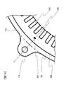
- FIG. 11 is a perspective view showing the stator 130 and the housing 112 of the rotating electrical machine 100 according to the second embodiment of the present invention
- FIG. 12 shows the fixing of the rotating electrical machine 100 according to the second embodiment of the present invention
- FIG. 6 is a schematic plan view showing a state in which the core iron core 132 is fixed to the housing 112 by shrink fitting or press fitting.
- the same or corresponding parts as those in the first embodiment are denoted by the same reference numerals and description thereof is omitted.
- FIG. 12 the illustration of the stator coil 138 and the insulating paper 300 disposed inside the slot 420 is omitted.
- a plurality of welding portions 200 as reinforcing portions are provided at positions corresponding to the flanges 115 on the outer peripheral portion of the stator core 132. According to the second embodiment, the same effects as (1) to (4) described in the first embodiment can be obtained. According to the second embodiment, the rigidity can be further improved by providing a plurality of welded portions 200, so that it is possible to cope with a case where a shrinkage allowance for press fitting or press fitting is large.
- the welded portions 200 may be provided at a total of three locations near the center of the flange 115 and near both ends of the flange 115 so as to correspond to the flange 115, or near both ends of the flange 115. You may install in two places.
- the welded portion 200 can be appropriately provided in the vicinity of the portion where the flange 115 abuts on the outer peripheral portion of the stator core 132.
- FIG. 13 is a schematic plan view showing a state where the stator core 132 of the rotating electrical machine 100 according to the third embodiment of the present invention is fixed to the housing 112 by shrink fitting or press fitting.
- the same or corresponding parts as those in the first embodiment are denoted by the same reference numerals and description thereof is omitted.
- illustration of the stator coil 138 and the insulating paper 300 is omitted.
- the welded portion 200 is provided on the bottom surface of the slot 420 at a position corresponding to the flange 115. That is, the welded portion 200 as a reinforcing portion is provided at a position corresponding to the flange 115 in the inner peripheral portion of the stator core 132.
- the same effects as (1) to (4) described in the first embodiment can be obtained.
- the rigidity can be further improved. It is also possible to cope with a case where the margin for tightening is large.
- FIG. 14 is a schematic plan view showing a state where the stator core 132 of the rotating electrical machine 100 according to the fourth embodiment of the present invention is fixed to the housing 112 by shrink fitting or press fitting.
- the same or corresponding parts as those in the first embodiment are denoted by the same reference numerals and description thereof is omitted.
- illustration of the stator coil 138 and the insulating paper 300 is omitted.
- the welded portion 200 is provided on the outer peripheral portion of the stator core 132 and the bottom surface of the slot 420. That is, the welded portion 200 as the reinforcing portion is provided at a position corresponding to the flange 115 in the outer peripheral portion and the inner peripheral portion of the stator core 132. According to the fourth embodiment, the rigidity of the stator core 132 is further improved by providing the welded portions 200 not only on one of the outer peripheral portion and the inner peripheral portion, but also on the first portion described above. The same effects as those of the third embodiment can be obtained.
- FIG. 15 is a schematic plan view showing a state where the stator core 132 of the rotating electrical machine 100 according to the fifth embodiment of the present invention is fixed to the housing 112 by shrink fitting or press fitting
- FIG. It is a schematic diagram which shows the cross section.
- the same or corresponding parts as those in the first embodiment are denoted by the same reference numerals and description thereof is omitted.
- illustration of the stator coil 138 and the insulating paper 300 is omitted.
- the caulking portion 201 for laminating and fixing the electromagnetic steel plates 133 constituting the stator core 132 is formed as a reinforcing portion that increases the rigidity of the portion corresponding to the flange 115. Since the caulking portion 201 is provided on the central axis X of the tooth 430, a sufficient flow of magnetic flux can be ensured.
- the caulking part 201 has a trapezoidal convex part and a concave part formed in the laminating direction of the electromagnetic steel sheet 133 using a punch or the like.
- the caulking portion 201 is not limited to the case where V caulking is adopted, and round caulking may be adopted.
- the caulking portion 201 since the caulking portion 201 has a function as a reinforcing portion, the cases (1) to (4) described in the first embodiment when the tightening allowance is relatively small. ) Has the same effect.
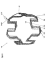
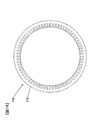
- FIG. 17 is a perspective view showing a stator core 132 of the rotating electrical machine 100 according to the sixth embodiment of the present invention.
- the stator core 132 can be manufactured by so-called rolling, so that the shape accuracy can be improved.
- Spinning is a method for manufacturing a stator core 132 in which a plurality of laminates 134 each made up of a predetermined number of electromagnetic steel sheets 133 are sequentially shifted by a predetermined angle in the circumferential direction, thereby leveling the thickness deviation. .
- the six cores 134 are rotated by 60 degrees to form the stator core 132.
- the stator core 132 When the stator core 132 is formed by rolling and stacking, it is necessary to previously form the welding grooves 210 at a predetermined interval, and to match the welding grooves 210 of the stacked body 134 that are arranged with a predetermined angle shift.
- the welding groove 210 is provided every 30 degrees.
- the position where the welding groove 210 is formed may be determined in advance in consideration of turning and stacking.
- the position and shape of the flange 115 depend on the shape of the engine case or transmission case to which the rotating electrical machine 100 is attached. Because of the difference, as shown in FIG. 18, it is preferable to provide weld grooves 210 in the outer peripheral portion on the central axis of all the teeth 430 of the stator core 132 in advance. Thereby, whatever position the flange 115 is, it is preferable because the welding groove 210 of each laminated body 134 can be made to coincide at a position corresponding to the flange 115 at the time of rolling. Since the welding groove 210 is formed on the central axis of the teeth 430, the flow of magnetic flux is not hindered in a portion where the magnetic flux density is high.
- the weld core 200 is not formed in all the weld grooves 210 but the stator core 132 is sintered.
- the housing 112 is fitted or fixed by fitting or press-fitting, the welded portion 200 is provided in the welding groove 210 disposed corresponding to the flange 115 of the housing 112. According to the sixth embodiment, the same effects as (1) to (4) described in the first embodiment can be obtained.
- the reinforcing part is not limited to the case where either one of the welded part 200 or the caulking part 201 is adopted, and the welding part 200 and the caulking part 201 may be combined to form a reinforcing part.
- the caulking portion 201 may be formed as a reinforcing portion in a portion where the small flange 115 is located
- the welded portion 200 may be formed as a reinforcing portion in a portion where the large flange 115 is located. You may form both the welding part 200 and the crimping part 201 in the part in which the big flange 115 is located.
- the welded portion 200 for laminating and fixing the stator core 132 and the caulking portion 201 have a function as a reinforcing portion
- the welded portion 200 for connecting the electromagnetic steel sheet 133 It is good also as providing a reinforcement part separately from the crimping part 201.
- the welded part 200 may be provided not only for connecting the electromagnetic steel sheets 133 but to serve as a reinforcing part. That is, the reinforcing portion can be provided only in the vicinity of the flange 115 provided at one end of the housing 112. In other words, the reinforcing portion can be provided only around one end side of the stator core 132.
- a member such as a bar is attached to the outer peripheral portion of the stator core 132 instead of the welded portion 200 and the caulking portion 201.
- the reinforcing portion may be provided by being fitted in a groove provided and parallel to the axial direction of the stator core 132 and fixed by welding or the like.
- stator core 132 has been described only with respect to the integral core in which the plurality of teeth 430 are integrated with the core back 440, the stator core 132 to which the present invention is applicable is not limited to this.
- the present invention can also be applied to a case where a stator core 132 made of a plurality of divided cores is fitted and fixed to the housing 112 by shrink fitting or press fitting.
- the present invention is not limited to the case where it is applied to the stator core 132 to which the segment type coil is attached. Thereby, the stress applied to the stator coil 138 due to the deformation of the stator core 132 can be suppressed, and damage to the insulating film of the coil conductor can be prevented.
Abstract
Une machine dynamoélectrique comprend un logement cylindrique ayant des rebords montés sur un carter ; un stator ayant un noyau de stator cylindrique fixé au logement par un assemblage par contraction ou un assemblage par pression ; et un rotor disposé en rotation dans le stator. Le noyau de stator est formé en empilant des plaques d'acier, et des sections de soudure pour empêcher la déformation des plaques d'acier sont prévues sur le noyau de stator à des positions correspondant aux rebords du logement.
Priority Applications (3)
| Application Number | Priority Date | Filing Date | Title |
|---|---|---|---|
| US13/881,239 US20130221781A1 (en) | 2010-11-08 | 2011-11-01 | Rotating Electrical Machine |
| CN201180053827.3A CN103201931B (zh) | 2010-11-08 | 2011-11-01 | 旋转电机 |
| EP11840112.4A EP2639933B1 (fr) | 2010-11-08 | 2011-11-01 | Machine dynamoélectrique |
Applications Claiming Priority (2)
| Application Number | Priority Date | Filing Date | Title |
|---|---|---|---|
| JP2010-249513 | 2010-11-08 | ||
| JP2010249513A JP5480106B2 (ja) | 2010-11-08 | 2010-11-08 | 回転電機 |
Publications (1)
| Publication Number | Publication Date |
|---|---|
| WO2012063684A1 true WO2012063684A1 (fr) | 2012-05-18 |
Family
ID=46050834
Family Applications (1)
| Application Number | Title | Priority Date | Filing Date |
|---|---|---|---|
| PCT/JP2011/075194 WO2012063684A1 (fr) | 2010-11-08 | 2011-11-01 | Machine dynamoélectrique |
Country Status (5)
| Country | Link |
|---|---|
| US (1) | US20130221781A1 (fr) |
| EP (1) | EP2639933B1 (fr) |
| JP (1) | JP5480106B2 (fr) |
| CN (1) | CN103201931B (fr) |
| WO (1) | WO2012063684A1 (fr) |
Families Citing this family (17)
| Publication number | Priority date | Publication date | Assignee | Title |
|---|---|---|---|---|
| CN103545994A (zh) * | 2013-10-24 | 2014-01-29 | 山东华力电机集团股份有限公司 | 一种低损耗鼠笼式电机转子的制备方法 |
| CN104052173A (zh) * | 2014-07-01 | 2014-09-17 | 柏科(常熟)电机有限公司 | 一种用于汽车发电机的定子 |
| CN106605355B (zh) * | 2014-09-29 | 2019-03-08 | 日立汽车系统株式会社 | 旋转电机的定子以及具备该旋转电机的定子的旋转电机 |
| JP2016140172A (ja) * | 2015-01-27 | 2016-08-04 | サンデンホールディングス株式会社 | 電動圧縮機 |
| JP5987940B2 (ja) * | 2015-03-05 | 2016-09-07 | ソニー株式会社 | モータ、アクチュエータ及び医療用支持アーム装置 |
| JPWO2017038326A1 (ja) * | 2015-09-02 | 2018-02-22 | 日立オートモティブシステムズ株式会社 | 回転子、これを備えた回転電機、及び回転子の製造方法 |
| EP3468014B1 (fr) * | 2016-06-01 | 2021-07-21 | Mitsubishi Electric Corporation | Machine électrique tournante |
| DE112016007430T5 (de) * | 2016-11-11 | 2019-07-25 | Mitsubishi Electric Corporation | Stator einer elektrischen Drehmaschine und Herstellungsverfahren dafür |
| FR3059847B1 (fr) * | 2016-12-06 | 2020-10-16 | Valeo Equip Electr Moteur | Machine electrique tournante ayant un faible bruit acoustique d'origine electromagnetique |
| FR3059848B1 (fr) * | 2016-12-06 | 2021-03-19 | Valeo Equip Electr Moteur | Machine electrique tournante ayant un faible bruit acoustique d'origine electromagnetique |
| GB2563613B (en) * | 2017-06-20 | 2021-10-20 | Dyson Technology Ltd | A brushless motor and stator therefor |
| JP7229659B2 (ja) * | 2017-11-02 | 2023-02-28 | 住友重機械工業株式会社 | 動力伝達装置 |
| NL2023483B1 (en) * | 2019-07-11 | 2021-02-03 | Tecnotion Assets B V | Permanent Magnet Synchronous Torque Motor |
| US11462981B2 (en) | 2019-08-28 | 2022-10-04 | Hossam Abdou | Electric motor |
| JP7278398B2 (ja) * | 2019-10-02 | 2023-05-19 | 三菱電機株式会社 | 回転電機 |
| US11025107B2 (en) * | 2019-10-30 | 2021-06-01 | Maxxwell Motors, Inc. | Fan impeller to cool an axial flux rotating machine, and applications thereof |
| JP2022089509A (ja) * | 2020-12-04 | 2022-06-16 | 日立Astemo株式会社 | 制御装置 |
Citations (6)
| Publication number | Priority date | Publication date | Assignee | Title |
|---|---|---|---|---|
| JPH10174327A (ja) * | 1996-12-16 | 1998-06-26 | Hitachi Ltd | 永久磁石回転子とその製造方法 |
| JP2000224787A (ja) * | 1999-01-27 | 2000-08-11 | Denso Corp | 密閉型電動圧縮機 |
| JP2002291184A (ja) | 2001-03-28 | 2002-10-04 | Mitsubishi Electric Corp | 回転電機の固定子および固定子鉄心並びにその製造方法 |
| JP2009072035A (ja) * | 2007-09-18 | 2009-04-02 | Meidensha Corp | 回転電機の回転子コア |
| JP2010226790A (ja) * | 2009-03-19 | 2010-10-07 | Toyota Motor Corp | ステータコアの支持構造およびその構造を有する車両駆動装置 |
| JP2010249513A (ja) | 2009-04-10 | 2010-11-04 | Tdk Corp | 外観検査装置 |
Family Cites Families (8)
| Publication number | Priority date | Publication date | Assignee | Title |
|---|---|---|---|---|
| FR2093227A5 (fr) * | 1970-06-05 | 1972-01-28 | Wagner Electric Corp | |
| ZA77644B (en) * | 1976-02-21 | 1977-12-28 | Lucas Industries Ltd | Dynamo electric machine stator body |
| JPS5843150A (ja) * | 1981-09-08 | 1983-03-12 | Fanuc Ltd | 固定子 |
| CA2860515C (fr) * | 2005-10-03 | 2017-05-30 | Letourneau Technologies Drilling Systems, Inc. | Systeme de forage a transmission superieure a entrainement direct |
| ITMI20070508A1 (it) * | 2007-03-14 | 2008-09-15 | Corrada Spa | Articolo laminare per uso elettrico procedimento e macchine per realizzare detto articolo laminare |
| DE112008002326T5 (de) * | 2007-12-27 | 2010-07-22 | Aisin Aw Co., Ltd. | Stator und diesen verwendende rotierende elektrische Maschine |
| JP2010068569A (ja) * | 2008-09-09 | 2010-03-25 | Aisin Seiki Co Ltd | ステータ |
| JP5260399B2 (ja) * | 2009-04-24 | 2013-08-14 | 日立オートモティブシステムズ株式会社 | 車両駆動用回転電機およびそれを用いた車両 |
-
2010
- 2010-11-08 JP JP2010249513A patent/JP5480106B2/ja active Active
-
2011
- 2011-11-01 EP EP11840112.4A patent/EP2639933B1/fr active Active
- 2011-11-01 US US13/881,239 patent/US20130221781A1/en not_active Abandoned
- 2011-11-01 CN CN201180053827.3A patent/CN103201931B/zh active Active
- 2011-11-01 WO PCT/JP2011/075194 patent/WO2012063684A1/fr active Application Filing
Patent Citations (6)
| Publication number | Priority date | Publication date | Assignee | Title |
|---|---|---|---|---|
| JPH10174327A (ja) * | 1996-12-16 | 1998-06-26 | Hitachi Ltd | 永久磁石回転子とその製造方法 |
| JP2000224787A (ja) * | 1999-01-27 | 2000-08-11 | Denso Corp | 密閉型電動圧縮機 |
| JP2002291184A (ja) | 2001-03-28 | 2002-10-04 | Mitsubishi Electric Corp | 回転電機の固定子および固定子鉄心並びにその製造方法 |
| JP2009072035A (ja) * | 2007-09-18 | 2009-04-02 | Meidensha Corp | 回転電機の回転子コア |
| JP2010226790A (ja) * | 2009-03-19 | 2010-10-07 | Toyota Motor Corp | ステータコアの支持構造およびその構造を有する車両駆動装置 |
| JP2010249513A (ja) | 2009-04-10 | 2010-11-04 | Tdk Corp | 外観検査装置 |
Non-Patent Citations (1)
| Title |
|---|
| See also references of EP2639933A4 |
Also Published As
| Publication number | Publication date |
|---|---|
| CN103201931A (zh) | 2013-07-10 |
| EP2639933B1 (fr) | 2020-08-05 |
| JP2012105388A (ja) | 2012-05-31 |
| EP2639933A4 (fr) | 2018-04-04 |
| EP2639933A1 (fr) | 2013-09-18 |
| CN103201931B (zh) | 2015-11-25 |
| JP5480106B2 (ja) | 2014-04-23 |
| US20130221781A1 (en) | 2013-08-29 |
Similar Documents
| Publication | Publication Date | Title |
|---|---|---|
| JP5480106B2 (ja) | 回転電機 | |
| JP5635470B2 (ja) | 回転電機および回転電機の製造方法 | |
| US8384263B2 (en) | Rotating electrical machine having a compact stator | |
| US9906086B2 (en) | Rotating electric machine including a stator with a connection portion having a corner portion and method for manufacturing same | |
| JP6563595B2 (ja) | 回転電機、及び回転電機の固定子 | |
| JP6402257B2 (ja) | 固定子コイル、これを備えた固定子、およびこれを備えた回転電機 | |
| US8653714B2 (en) | Stator for electric rotating machine | |
| WO2016035533A1 (fr) | Stator pour machine électrique rotative et machine électrique rotative équipée de celui-ci | |
| CN109478814B (zh) | 旋转电机的定子和旋转电机 | |
| JP6793257B2 (ja) | 回転電機の固定子、及び回転電機 | |
| WO2017038326A1 (fr) | Rotor, machine électrique tournante équipée de celui-ci et procédé de fabrication de rotor | |
| JP2013207946A (ja) | 回転電機 | |
| JP6009519B2 (ja) | 回転電機および回転電機の製造方法 | |
| JP2014082935A (ja) | 回転電機の固定子、およびこれを備えた回転電機 | |
| JP7150171B2 (ja) | 回転電機の固定子、端子台及び回転電機 | |
| CN112352368A (zh) | 旋转电机的定子、旋转电机以及旋转电机的定子的制造方法 | |
| WO2020013331A1 (fr) | Stator pour machine électrique rotative, machine électrique rotative, et procédé de production de stator pour machine électrique rotative | |
| JP6165828B2 (ja) | 固定子コイル、固定子鉄心、及び回転電機 | |
| JP2016163500A (ja) | 回転電機 |
Legal Events
| Date | Code | Title | Description |
|---|---|---|---|
| 121 | Ep: the epo has been informed by wipo that ep was designated in this application |
Ref document number: 11840112 Country of ref document: EP Kind code of ref document: A1 |
|
| WWE | Wipo information: entry into national phase |
Ref document number: 13881239 Country of ref document: US |
|
| WWE | Wipo information: entry into national phase |
Ref document number: 2011840112 Country of ref document: EP |
|
| NENP | Non-entry into the national phase |
Ref country code: DE |