WO2012057094A1 - Dispositif de communication - Google Patents
Dispositif de communication Download PDFInfo
- Publication number
- WO2012057094A1 WO2012057094A1 PCT/JP2011/074464 JP2011074464W WO2012057094A1 WO 2012057094 A1 WO2012057094 A1 WO 2012057094A1 JP 2011074464 W JP2011074464 W JP 2011074464W WO 2012057094 A1 WO2012057094 A1 WO 2012057094A1
- Authority
- WO
- WIPO (PCT)
- Prior art keywords
- transmission power
- reception
- wireless
- reception sensitivity
- control unit
- Prior art date
Links
Images


Classifications
-
- H—ELECTRICITY
- H04—ELECTRIC COMMUNICATION TECHNIQUE
- H04W—WIRELESS COMMUNICATION NETWORKS
- H04W52/00—Power management, e.g. TPC [Transmission Power Control], power saving or power classes
- H04W52/02—Power saving arrangements
- H04W52/0209—Power saving arrangements in terminal devices
-
- H—ELECTRICITY
- H04—ELECTRIC COMMUNICATION TECHNIQUE
- H04W—WIRELESS COMMUNICATION NETWORKS
- H04W52/00—Power management, e.g. TPC [Transmission Power Control], power saving or power classes
- H04W52/04—TPC
- H04W52/30—TPC using constraints in the total amount of available transmission power
- H04W52/36—TPC using constraints in the total amount of available transmission power with a discrete range or set of values, e.g. step size, ramping or offsets
- H04W52/367—Power values between minimum and maximum limits, e.g. dynamic range
-
- H—ELECTRICITY
- H04—ELECTRIC COMMUNICATION TECHNIQUE
- H04W—WIRELESS COMMUNICATION NETWORKS
- H04W52/00—Power management, e.g. TPC [Transmission Power Control], power saving or power classes
- H04W52/02—Power saving arrangements
- H04W52/0209—Power saving arrangements in terminal devices
- H04W52/0251—Power saving arrangements in terminal devices using monitoring of local events, e.g. events related to user activity
- H04W52/0254—Power saving arrangements in terminal devices using monitoring of local events, e.g. events related to user activity detecting a user operation or a tactile contact or a motion of the device
-
- Y—GENERAL TAGGING OF NEW TECHNOLOGICAL DEVELOPMENTS; GENERAL TAGGING OF CROSS-SECTIONAL TECHNOLOGIES SPANNING OVER SEVERAL SECTIONS OF THE IPC; TECHNICAL SUBJECTS COVERED BY FORMER USPC CROSS-REFERENCE ART COLLECTIONS [XRACs] AND DIGESTS
- Y02—TECHNOLOGIES OR APPLICATIONS FOR MITIGATION OR ADAPTATION AGAINST CLIMATE CHANGE
- Y02D—CLIMATE CHANGE MITIGATION TECHNOLOGIES IN INFORMATION AND COMMUNICATION TECHNOLOGIES [ICT], I.E. INFORMATION AND COMMUNICATION TECHNOLOGIES AIMING AT THE REDUCTION OF THEIR OWN ENERGY USE
- Y02D30/00—Reducing energy consumption in communication networks
- Y02D30/70—Reducing energy consumption in communication networks in wireless communication networks
Definitions
- the present invention relates to a wireless transceiver, and particularly relates to a transmission power control technique for the wireless transceiver.
- wireless terminals in mobile communication systems, such as mobile phones using batteries as power sources and mobile PCs with built-in communication devices, have become widespread, making full use of various power-saving technologies.
- Technology development is underway to extend the continuous operation time as much as possible.
- the transmission power is determined based on the signal strength and quality of a received signal received from a wireless base station (hereinafter referred to as a wireless base station) in a mobile communication system.
- Patent Document 1 is a technique for measuring transmission signal strength by measuring the strength of a received signal in wireless communication.
- the conventional wireless terminal cannot control transmission power as intended, the transmission power cannot be reduced by the user to suppress power consumption when the power is turned on. For this reason, in an environment where radio waves from radio base stations are difficult to reach, wireless terminals transmit at the maximum output, which is one of the causes of consuming power and shortening the continuous operation time against the user's expectation. It was.
- An object of the present invention is to provide a radio transceiver and its control means capable of suppressing unintentional power consumption and extending a continuous operation time by a user intentionally controlling transmission power. .
- the radio wave radiated from the radio base station with a predetermined transmission power is received by the radio terminal after receiving a propagation loss in the route up to reception.
- radio waves radiated from the wireless terminal are received by the wireless base station after receiving the same loss amount as the propagation loss on the route up to reception.
- the transmission loss is the same between the transmission side and the reception side, so communication is symmetrical.
- the maximum transmission power of a radio base station and a radio terminal is different. Even when the transmission output of the radio base station and the radio terminal is different, the system design is made so that “symmetry of communication” is maintained in consideration of the antenna characteristics and the noise figure of the receiver.
- An object of the present invention is to make it possible to vary transmission power according to a user's intention while ensuring “symmetry of communication”.
- the wireless transceiver of Invention 1 has transmission power control means and reception sensitivity control means, and the transmission power control means and reception sensitivity control means are controlled by a single operation. It is characterized by being.
- the control of the transmission power control means and the reception sensitivity control means by a single operation is performed in a state where the power of the wireless transceiver is turned on, for example, the power is turned on from off. This does not include the case where the upper limit value of transmission power and the reception sensitivity become 0 simultaneously.
- the wireless transceiver of the invention 2 has means for reducing the upper limit value of transmission power by a predetermined operation, and the upper limit value of transmission power reduced by the predetermined operation. And a means for reducing the reception performance accordingly.
- the wireless transceiver of Invention 3 is the above-described wireless transceiver, wherein the reception performance is reception sensitivity.
- the wireless transceiver of Invention 4 is the above-described wireless transceiver, wherein the reception performance is a reference value when it is determined that communication is established.
- the wireless transceiver according to Invention 5 is the above-described wireless transceiver, wherein the reception performance is an allowable value of an error rate of received data.
- the wireless transceiver according to Invention 6 has means for reducing the upper limit value of transmission power by a predetermined operation and the upper limit value of transmission power reduced by the predetermined operation. And a means for notifying the communication partner of the reception status when the reception performance is lowered or when the reception performance is lowered.
- the communication partner is provided with means for notifying the reception state when the reception performance is reduced or the reception performance is reduced according to the reduced upper limit of the transmission power, for example, the communication partner is a wireless transceiver If the configuration is such that the transmission power is controlled based on the reception status, the effect that the “symmetry of communication” is lost can be reduced.
- the wireless transceiver according to Invention 7 is the above-described wireless transceiver, wherein the reception performance is reception sensitivity.
- the wireless transceiver of Invention 8 is the above-described wireless transceiver, wherein the reception performance is a reference value when it is determined that communication is established.
- the wireless transceiver according to Invention 9 is the above-described wireless transceiver, wherein the reception performance is an allowable value of an error rate of received data.
- the wireless transceiver of the invention 10 is the above-described wireless transceiver, characterized by establishing communication with a counterpart in wireless transmission / reception stronger than a pre-registered radio wave intensity by the reduced reception sensitivity. To do.
- the wireless transceiver according to Invention 11 is the above-described wireless transmitter / receiver, which simultaneously reduces the upper limit value of transmission power and the reception sensitivity by a control signal generated by the predetermined operation of the user. It can be returned to normal.
- the wireless transmitter / receiver of the invention 12 is the above-described wireless transmitter / receiver, wherein an upper limit value of transmission power and a receiving sensitivity are set by a control signal generated by transmitting information from the outside and performing remote operation. At the same time, it can be lowered or returned to normal.
- the wireless transceiver according to Invention 13 is the above-described wireless transceiver, and transmits to the other party in information transmission registered in advance in a state where the upper limit value of transmission power and the reception sensitivity are lowered. In this case, the reduced upper limit of transmission power returns to normal.
- the wireless transmitter / receiver of the invention 14 is the above-described wireless transmitter / receiver, and has received an incoming call from the other party in information transmission registered in advance in a state where the upper limit value of transmission power and the reception sensitivity are lowered In this case, the reduced upper limit of transmission power returns to normal.
- the wireless transceiver of the invention 15 is the above-described wireless transceiver, and when a specific event set in advance is detected in a state where the upper limit value of transmission power and the reception sensitivity are reduced, The reduced upper limit value of transmission power returns to normal.
- the specific event refers to a state where the upper limit value of the reduced transmission power may be automatically returned to the normal state without any user operation.
- the reduced upper limit value of transmission power returns to normal.
- the wireless transceiver of the invention 16 has transmission power control means and reception sensitivity control means, and the transmission power control means and the reception sensitivity control means are common.
- the radio transmitter / receiver has a control signal, and by operating the control signal, the upper limit value of transmission power and the reception sensitivity can be reduced or returned to normal at the same time.
- a wireless transmitter / receiver that establishes communication with the other party in stronger wireless transmission / reception, has position detection means, and when it detects that it is a pre-registered area, it lowers the upper limit value of transmission power or returns to normal It can be returned.
- the wireless transceiver of the invention 17 is the above-described wireless transceiver, characterized in that the reception sensitivity is controlled in conjunction with the transmission output.
- the wireless transceiver according to Invention 18 is the above-described wireless transceiver, characterized in that the sensitivity is linked to the output.
- the user can determine the upper limit value of the transmission power of the wireless transceiver, and the user can control the transmission power, thereby reducing the power consumption and extending the continuous operation time.
- the effect of becoming is obtained.
- the effect that the influence on the human body of a radio frequency electromagnetic field can be weakened is also acquired.
- FIG. 6 is a diagram illustrating transmission power characteristics, reception sensitivity characteristics, and reception intensity characteristics of a conventional wireless terminal in a case where (A) to (c) are diagrams showing transmission power characteristics, reception sensitivity characteristics, and reception intensity characteristics of a conventional wireless terminal, and (d) to (f) are wireless communication according to the first embodiment. It is a figure which shows the transmission power characteristic, reception sensitivity characteristic, and reception intensity characteristic of a transmitter / receiver.
- the configuration of a mobile communication system that connects a mobile phone or a mobile PC with a built-in communication device includes at least a wireless terminal, a “wireless base station that is a counterpart in wireless transmission / reception” (hereinafter, a wireless base station), a public communication network, It consists of a “terminal device on the other side in information transmission”.
- the present invention is a technique that can be widely applied not only to wireless terminals in mobile communication systems and wireless base stations in mobile communication systems, but also to one-to-one wireless communication, etc.
- the wireless transceivers according to the first to fifth embodiments will be described as an example in which the present invention is applied to a wireless terminal in a mobile communication system.
- the transmission power of the wireless terminal in the conventional mobile communication system cannot be changed to a desired value intentionally by the user, and the intensity of the radio wave received from the wireless base station is measured.
- the wireless base station and the wireless terminal have determined the transmission power of the wireless terminal.
- transmission power that has not been changed by the user is referred to as “normal transmission power”, whereas transmission power that is intentionally changed by the user is referred to as “transmission power lower than normal”. Yes.
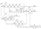
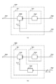
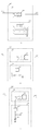
- FIG. 1 is a diagram showing a basic configuration of a radio transceiver according to the first embodiment.
- This wireless transceiver includes an “antenna” 111, a “receiver” 410, a “transmitter” 470, a “control signal generator” 450, and an “operation means” 114.
- the “receiver” 410 includes at least a “band limiter” 121, a “sensitivity controller” 122, an “automatic gain control amplifier” 123, a “channel selector” 126, and a “demodulator” 128.
- the “reception signal” 331 received by the “antenna” 111 is input to the “reception unit” 410.
- a “demodulation signal” 332 is output from the “reception unit” 410.
- the “demodulated signal” 332 includes “information transmitted by the base station”.
- the “sensitivity controller” 122 can change the reception sensitivity by the “correction control signal” 352 from the “control signal generator” 450.
- a circuit example of the “sensitivity controller” 122 is shown in FIG.
- the “sensitivity controller” 122 can be configured as shown in FIG.
- the “sensitivity controller” 122 has one end connected to the “band limiter” 121 and the anode terminal connected to the other end of the “first capacitor”.
- a “PIN diode” 564 having a cathode terminal grounded, a “resistance element” for inputting a “correction control signal” 352 from one end, and one end connected to the other end of the “resistance element” and the other end “PIN diode” 564 And a “second capacitor” having one end connected to the anode terminal of “PIN diode” 564 and the other end connected to “automatic gain control amplifier” 123. Has been.
- the “sensitivity controller” 122 may be configured as shown in FIG. 11B, for example.
- the “sensitivity controller” 122 includes a “first capacitor” whose one end is connected to the “band limiter” 121, a “second capacitor” whose one end is grounded, and one end that is The grounded “first resistance element”, the “second resistance element” for inputting the “correction control signal” 352 from one end, and the first gate terminal G1 connected to the other end of the “first capacitor” are connected to the second gate.
- a “dual gate field effect transistor” in which the terminal G2 is connected to the other ends of the “second capacitor”, “first resistance element”, and “second resistance element”, and a source terminal of the “dual gate field effect transistor” at one end A “third capacitor” connected to S and the other end grounded, a “third resistor element” having one end connected to the source terminal S of the “dual gate field effect transistor” and the other end grounded, and one end “ Dual gate electric field A “fourth resistor element” connected to the drain terminal D of the “effect transistor” and connected to the “power supply” VDD at the other end; and a “fourth capacitor” connected at one end to the “power supply” VDD and connected at the other end to the ground. , Having a “fifth capacitor” having one end connected to the drain terminal D of the “dual gate field effect transistor” and the other end connected to the “automatic gain control amplifier” 123.
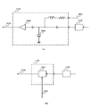
- the “transmitter” 470 includes at least a “carrier generator” 171, a “modulator” 172, and a “transmission power controller” 173.
- the modulation signal” 374 including “information to be transmitted to the other party” is input to the “transmission unit” 470.
- “Transmission unit” 470 generates “transmission signal” 375 and outputs it to “antenna” 111.
- the “transmission power controller” 173 can vary the transmission power by the “correction control signal” 352 from the “control signal generator” 450.
- a circuit example of the “transmission power controller” 173 is shown in FIG.
- the “transmission power controller” 173 can be configured as shown in FIG.
- the “transmission power controller” 122 has one end connected to the “modulator” 172 and the anode terminal connected to the other end of the “first capacitor”.
- a “PIN diode” 564 having a cathode terminal grounded, a “resistance element” for inputting a “correction control signal” 352 from one end, and one end connected to the other end of the “resistance element” and the other end “PIN diode” 564
- the “coil” connected to the anode terminal of the first terminal, the “second capacitor” connected to the anode terminal of the “PIN diode” 564 at one end, and the output terminal connected to the other end of the “second capacitor” from the output terminal
- a “power amplifier” 566 that outputs a “transmission signal” 375.
- the “transmission power controller” 173 can be configured as shown in FIG. In the example of FIG. 12B, the “transmission power controller” 122 inputs the output signal from the “modulator” 172 and the “correction control signal” 352 from the input terminal, and outputs the “transmission signal” 375 from the output terminal.
- the “variable gain power amplifier” 567 is configured.
- the “operation means” 114 generates an “operation signal” 315 based on an operation performed by the user or the like, and outputs it to the “control signal generation unit” 450.
- the “operation signal” 315 from the “operation means” 114 is input to the “control signal generator” 450.
- “Control signal generator” 450 outputs “correction control signal” 352 determined based on the state of “operation signal” 315.
- the “control signal generator” 450 outputs the generated “correction control signal” 352 to the “transmitter” 470 and the “receiver” 410 in common.
- the “transmission unit” 470 and the “reception unit” 410 are controlled by a single operation from the “operation means” 114.
- control signal generator 450 A circuit example of the “control signal generator” 450 is shown in FIG.
- the “control signal generator” 450 can be configured as shown in FIG.
- the “control signal generator” 450 includes a “first resistance element” having one end connected to the “power supply” VDD and a “second resistance” having one end connected to the “power supply” VDD.
- the “control signal generator” 450 can be configured as shown in FIG. In the example of FIG. 13B, the “control signal generator” 450 includes a “first resistance element” whose one end is connected to the “power supply” VDD and a “second resistor” whose one end is connected to the “power supply” VDD.
- a“ flip-flop ”577 in which the set terminal S is connected to the other end of the“ first resistance element ”and the reset terminal R is connected to the other end of the“ second resistance element ”, and an output enable terminal OE Is connected to the output terminal Q of the “flip-flop” 577 and outputs a “correction control signal” 352 from the output terminal, and one end is n + 1 pieces of the first “three-state buffer” 576.
- N + 1 “first switch elements” connected to the respective input terminals of the first and second terminals are grounded, and n of the first “three-state buffer” 576 having one end connected to the “power supply” VDD and the other end.
- n + 1 “third resistance element” connected to each of the one input terminal and the output enable terminal OE are connected to the inverting output terminal ⁇ Q of the “flip-flop” 577 and the “correction control signal” is output from the output terminal.
- Switch element” and n + 1 “fourth resistance elements” having one end connected to the “power supply” VDD and the other end connected to each of the n + 1 input terminals of the second “three-state buffer” 576. Configured.
- the “operation unit” 114 has a “first switch element” whose one end is connected to the set terminal S of the “flip-flop” 577 and the other end is grounded, and one end is The “flip-flop” 577 is connected to the reset terminal R and has the other end connected to the “second switch element”.
- control signal generation unit” 450 sets the “correction control signal” to a value that maintains “normal transmission power” and “normal reception sensitivity”. 352 is generated and output to the “transmission unit” 470 and the “reception unit” 410.
- the “transmission power controller” 173 that is a component of the “transmission unit” 470 is input with the “correction control signal” 352 that maintains the “normal transmission power”, the “transmission unit” 470 The “transmission signal” 375 is output by “normal transmission power”.
- the “sensitivity controller” 122 that is a component of the “reception unit” 410 is input with the “correction control signal” 352 that maintains the “normal reception sensitivity”, the “reception unit” 410 Generates “demodulated signal” 332 according to “normal reception sensitivity”.
- the wireless transceiver determines the transmission power according to the intensity of the radio wave received from the wireless base station.
- the wireless transceiver reduces the transmission power. Conversely, if the radio wave received from the radio base station is weak, the radio transceiver increases the transmission power.
- the wireless transceiver transmits with the minimum necessary transmission power. For example, when the radio transceiver is receiving radio waves from a radio base station, if the transmission power of the radio transceiver is simply reduced, it will not reach the radio base station and communication will not be possible. In addition, the “transmission symmetry” between the transmission output and the reception sensitivity of the wireless transceiver as viewed from the wireless base station is broken. For this reason, the radio base station and the base station network cannot operate normally for this radio transceiver.
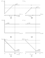
- FIGS. 21 (a) to 21 (c) are diagrams showing transmission power characteristics, reception sensitivity characteristics, and reception strength characteristics of a conventional wireless terminal.
- FIGS. 21 (d) to 21 (f) are upper limit values of transmission power.
- FIG. 6 is a diagram illustrating a transmission power characteristic, a reception sensitivity characteristic, and a reception intensity characteristic of a conventional wireless terminal when only the frequency is reduced.
- FIGS. 22 (d) to (f) are diagrams showing transmission power characteristics, reception sensitivity characteristics, and reception strength characteristics of a conventional wireless terminal, and FIGS. 22 (d) to (f) are shown in this embodiment. It is a figure which shows the transmission power characteristic of the radio
- the vertical axis 800 in FIGS. 21A, 21D, 22A, and 22D represents transmission power
- the vertical axes in FIGS. 21B, 21E, 22B, and 22E represents transmission power
- An axis 801 represents reception sensitivity
- a vertical axis 802 in FIGS. 21C and 21F and FIGS. 21C and 21F represents reception intensity
- the horizontal axis 803 of each graph in FIGS. 21 and 22 indicates the propagation loss ( ⁇ distance) between the conventional wireless terminal (or the wireless transceiver according to this embodiment) and the wireless base station. Yes.
- the transmission power increases as the propagation loss with the wireless base station increases (that is, as the radio wave received from the wireless base station becomes weaker).
- the transmission power is controlled.
- the maximum transmission power 804 that can be exhibited by the wireless terminal
- the maximum transmission power 804 remains constant, and a signal is transmitted to the radio base station at a point where the propagation loss is slightly higher than the point at which the maximum transmission power 804 is reached. Can no longer communicate.
- the reception sensitivity is set to the maximum reception sensitivity 805 that can be exhibited by the wireless terminal regardless of the propagation loss. Therefore, the reception intensity is shown in FIG.
- the maximum reception strength 815 decreases, and when the propagation loss decreases to an allowable value 806, it becomes impossible to receive a signal from the radio base station.
- the range 807 in which the wireless terminal can transmit a signal to the wireless base station and the range 808 in which the wireless terminal can receive a signal from the wireless base station are the same. Is maintained. This is because the system is designed so that “communication symmetry” is maintained in consideration of the characteristics of the antenna and the noise figure of the receiver. Therefore, when the propagation loss exceeds the ranges 807 and 808 and increases to the ranges 809 and 810, the wireless terminal cannot display communication with the wireless base station, so “out of range” is displayed.
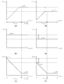
- the transmission power becomes constant at the constant value 811 when reaching the constant value 811 as shown in FIG.
- the signal cannot be transmitted to the radio base station at a point slightly higher than the point at which the value reaches a certain value 811. Therefore, the range 812 in which the radio terminal can transmit a signal to the radio base station is smaller than when the upper limit value of the transmission power is not lowered.
- the reception sensitivity is set to the maximum reception sensitivity 805 regardless of the propagation loss as shown in FIG. 21 (e), so the reception intensity is high in the propagation loss as shown in FIG. 21 (f).
- the maximum reception strength 815 decreases, and when it decreases to an allowable value 806, a signal from the radio base station cannot be received. Accordingly, the range 808 in which the wireless terminal can receive a signal from the wireless base station is the same as when the upper limit value of the transmission power is not reduced.
- the range 812 in which the wireless terminal can transmit signals to the wireless base station does not match the range 808 in which the wireless terminal can receive signals from the wireless base station. Collapses. That is, when the propagation loss exceeds the range 812 but does not exceed the range 808, a one-way communication state in which a signal cannot be transmitted to the radio base station but a signal can be received from the radio base station Therefore, the wireless terminal is in a state where it cannot make a call to the wireless base station even though “out of service area” is not displayed. This not only confuses the user, but also prevents the radio base station and the base station network from operating normally with respect to the radio terminal as described above.
- the reception sensitivity is reduced to a constant value 813 in accordance with the reduced upper limit value 811 of the transmission power.
- the reception sensitivity is increased to the maximum reception sensitivity 805 (for example, 0 [dB]) to a constant value 813 (for example, ⁇ 10 [dB]).
- the reception intensity When the reception sensitivity decreases, the reception intensity also becomes a predetermined value (corresponding to a difference between the maximum reception sensitivity 805 and a constant value 813) as the propagation loss increases as the propagation loss increases, as shown in FIG.
- a predetermined value corresponding to a difference between the maximum reception sensitivity 805 and a constant value 813
- the range 814 in which the radio transceiver can receive a signal from the radio base station is smaller than when the reception sensitivity is not lowered.
- the range 812 in which the radio transceiver can transmit signals to the radio base station and the range 814 in which the radio transceiver can receive signals from the radio base station coincide with each other, so that “communication symmetry” is maintained.
- the reception sensitivity may be reduced according to the upper limit value of the transmission power.
- the range in which the radio transceiver can receive signals from the radio base station (reception range) is It is preferable to lower the signal so as to coincide with a range (transmission range) in which a signal can be transmitted.
- the reception range and the transmission range do not necessarily need to be the same, and if the mismatch between the reception range and the transmission range can be reduced as compared with the case where the reception sensitivity is not lowered at all, the “symmetry of communication” is lost. Since the degree can be reduced, when the upper limit value of the transmission power is reduced, it is only necessary to reduce the reception sensitivity so that the reception range matches the transmission range or the mismatched portion becomes small. it can.
- the operation when the transmission power is changed to “transmission power lower than normal” and the operation for preventing the above-described problem are referred to as a “sensitivity controller” 122 in a variable attenuator ( An example using a variable (Attenuator) will be described below.
- the user tries to manually change the transmission power increasing or decreasing within a predetermined range to 1/10.
- the “correction control signal” 352 has a value of 1/10.
- the “transmission power controller” 173 sets the transmission power to 1/10 of the original maximum transmission power.
- “Sensitivity controller” 122 (variable attenuator) sets the attenuation rate to 1/10. Therefore, the radio transceiver according to the present embodiment can switch the transmission power to “transmission power lower than normal” or return to “normal transmission power” by the operation performed by the user. In conjunction with the switching of the transmission power, the reception sensitivity is switched to “reception sensitivity lower than normal” or returned to “normal reception sensitivity”.
- the “sensitivity controller” 122 that is a component of the “receiving unit” 410 can be implemented by a variable attenuator and a variable amplifier.
- the radio transceiver decreases the upper limit value of the transmission power by operating the “operation means” 114, and decreases the reception sensitivity according to the lower limit value of the transmission power.
- the user can determine the upper limit value of the transmission power of the wireless transceiver, and the user can control the transmission power to reduce power consumption and extend the continuous operation time. Further, the influence of the radio frequency electromagnetic field on the human body can be weakened. Furthermore, the degree of “communication symmetry” breaking can be reduced.
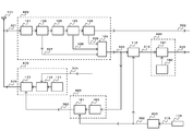
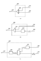
- FIG. 2 is a diagram illustrating a basic configuration of a radio transceiver according to the second embodiment.
- This wireless transceiver includes an “antenna” 111, a “reception unit” 420, a “communication establishment determination unit” 430, a “transmission power determination unit” 460, a “transmission unit” 470, a “control signal generation unit” 450, an “operation” Means "114.
- Receiveiver 420 includes at least “band limiter” 121, “automatic gain control amplifier A” 124, “automatic gain control amplifier B” 125, “channel selector” 126, “demodulator” 128, “reception level generation” Instrument “129.
- the “reception signal” 331 received by the “antenna” 111 is input to the “reception unit” 420.
- a “demodulated signal” 332 is output from the “receiving unit” 420.
- the “demodulated signal” 332 includes “information transmitted by the base station”.
- the “reception level generator” 129 converts the strength and quality of the “reception signal” 331 input to the “reception unit” 420 into a “reception level signal” 335 and outputs the result.
- the “reception level generator” 129 outputs the “reception level signal” 335 to the “communication establishment determination unit” 430 and the “transmission power determination unit” 460 simultaneously.
- the “communication establishment determination unit” 430 includes at least a “level comparator” 141.
- the “reception level signal” 335 from the “reception unit” 420 and the “correction control signal” 352 from the “control signal generation unit” 450 are input to the “communication establishment determination unit” 430.
- the “communication establishment determination unit” 430 compares the value of the “reception level signal” 335 with the value of the “correction control signal” 352 and determines the state of the “communication establishment determination signal” 343.
- the “communication establishment determination signal” 343 is output in a state of either “communication establishment is possible” or “communication establishment is not possible”.
- FIG. 15A A circuit example of the “communication establishment determination unit” 430 is shown in FIG.
- the “communication establishment determination unit” 430 can be configured as shown in FIG.
- the “communication establishment determination unit” 430 includes a “level comparator” 141.
- the “level comparator” 141 includes a “comparator” 553 that is an analog circuit.
- “Comparator” 553 inputs “reception level signal” 335 from the non-inverting input terminal, inputs “correction control signal” 352 from the inverting input terminal, and outputs “communication establishment judgment signal” 343 from the output terminal. .
- the “communication establishment determination unit” 430 can be configured as shown in FIG. In the example of FIG. 15B, the “communication establishment determination unit” 430 includes a “level comparator” 141.
- the “level comparator” 141 is configured to include an “A / D converter” 568 that inputs a “reception level signal” 335 and performs A / D conversion, and a weighted “comparator” 558 by a logic circuit. .
- the “comparator” 558 inputs the A / D converted “reception level signal” 335 from the first input terminal, and inputs the “correction control signal” 352 (digital signal) from the second input terminal.
- the determination signal 343 is output from the output terminal.
- the “transmission power determination unit” 460 includes at least a “level calculator” 163 and a “level limiter” 161.
- “Reception level signal” 335 from “reception unit” 420 and “correction control signal” 352 from “control signal generation unit” 450 are input to “transmission power determination unit” 460.
- the “level calculator” 163 of the “transmission power determination unit” 460 determines the transmission power from the value of the “reception level signal” 335.
- the “level limiter” 161 checks whether or not the transmission power determined by the “level calculator” 163 exceeds the upper limit value based on the value of the “correction control signal” 352. Change the power to the upper limit. This is output as “transmission power control signal” 362 to “transmission unit” 470.
- the upper limit value-limited “transmission power control signal” 362 is output, and the transmission power is suppressed to a desired value or less.
- the “transmission power determination unit” 460 can be configured as shown in FIG.
- the “transmission power determining unit” 460 includes a “level limiter” 161 and a “level calculator” 163.
- the “level calculator” 163 includes an “inverting amplifier” 533 that is an analog circuit.
- the “inverting amplifier” 533 receives the “reception level signal” 335, amplifies it, and outputs it.
- the “level limiter” 161 includes a “level limiter” 559 based on an analog circuit.
- the “level limiter” 559 inputs the amplified “reception level signal” 335 from the input terminal, inputs the “correction control signal” 352 as the “level limit reference voltage” 717, and outputs the “transmission power limit signal” 362. Output from the output terminal.
- the “transmission power determination unit” 460 can be configured as shown in FIG. In the example of FIG. 16B, the “transmission power determination unit” 460 includes a “level limiter” 161 and a “level calculator” 163.
- the “level calculator” 163 includes an “inverting amplifier” 533 that is an analog circuit.
- the “inverting amplifier” 533 receives the “reception level signal” 335, amplifies it, and outputs it.
- the “level limiter” 161 includes a “D / A converter” 569 that inputs a “correction control signal” 352 (digital signal) and performs D / A conversion, and a “level limiter” 559 using an analog circuit. Has been.
- the “level limiter” 559 inputs the amplified “reception level signal” 335 from the input terminal, inputs the D / A converted “correction control signal” 352 as the “level limit reference voltage” 717, and “transmits” “Power limit signal” 362 is output from the output terminal.
- the “transmission power determination unit” 460 can be configured as shown in FIG. In the example of FIG. 17A, the “transmission power determination unit” 460 is configured to include a “subtractor” 555 using an analog circuit.
- the “subtractor” 555 receives the “reception level signal” 335 and the “correction control signal” 352, subtracts the “correction control signal” 352 from the “reception level signal” 335, and obtains the “transmission power control” as the subtraction result.
- a signal “362” is output from the output terminal.
- the “transmission power determination unit” 460 can be configured as shown in FIG. In the example of FIG. 17B, the “transmission power determination unit” 460 receives the “correction control signal” 352 (digital signal) and performs “D / A conversion” 569 for D / A conversion, and “subtraction” by an analog circuit.
- Device "555. The “subtractor” 555 receives the “reception level signal” 335 and the D / A converted “correction control signal” 352, subtracts the “correction control signal” 352 from the “reception level signal” 335, and the subtraction result
- the “transmission power control signal” 362 is output from the output terminal.
- the “transmission power determination unit” 460 can be configured as shown in FIG. In the example of FIG. 17C, the “transmission power determination unit” 460 inputs an “reception level signal” 335 and performs A / D conversion, an “A / D converter” 568, and a “subtractor” 557 based on a logic circuit. , “D / A converter” 569 which D / A converts the output signal from “Subtractor” 557 and outputs “Transmission power control signal” 362. The “subtractor” 557 receives the A / D converted “reception level signal” 335 and “correction control signal” 352 (digital signal), and subtracts the “correction control signal” 352 from the “reception level signal” 335. The subtraction result is output from the output terminal.
- the “transmitter” 470 includes at least a “carrier generator” 171, a “modulator” 172, and a “transmission power controller” 173.
- the modulation signal” 374 including “information to be delivered to the other party” is input to the “transmission unit” 470.
- “Transmission unit” 470 generates “transmission signal” 375 and outputs it to “antenna” 111.
- the “transmission power controller” 173 can vary the transmission power by the “transmission power control signal” 362 from the “transmission power determination unit” 460.
- a circuit example of the “transmission power controller” 173 is as shown in FIG.
- the operation means” 114 generates an “operation signal” 315 based on the performed operation, and outputs it to the “control signal generator” 450.
- the “operation signal” 315 from the “operation means” 114 is input to the “control signal generator” 450.
- the “control signal generator” 450 determines the value of the “correction control signal” 352 to be generated based on the state of the “operation signal” 315.
- the “control signal generation unit” 450 outputs the generated “correction control signal” 352 to the “transmission power determination unit” 460 and the “communication establishment determination unit” 430.
- a circuit example of the “control signal generator” 450 is as shown in FIG.
- “Reception level generator” 129 includes “automatic gain control amplifier A” 124, “automatic gain control amplifier B” 125, “demodulator” 128, etc. that constitute “reception unit” 420.
- the “reception level signal” 335 is generated based on the result of evaluating the above information and evaluating the information.
- Information such as signal strength and signal error rate may be used alone.
- a plurality of information may be used. In that case, a plurality of pieces of information may be input in parallel or added together.
- the radio transmitter / receiver receives the radio wave transmitted by the radio base station, and a “reception level signal” 335 corresponding to the received signal strength is output.
- the “communication establishment determination unit” 430 determines whether the radio wave of the transmission output limited by the “correction control signal” 352 reaches the wireless base station by determining from the value of the “reception level signal” 335 and can establish communication. Make a judgment.
- the wireless transceiver can be configured not to start communication.
- determining that communication is established by the “reception level signal” 335 and restricting communication with a radio base station having a reception signal weaker than a pre-registered radio wave intensity does not reduce reception sensitivity. This is the same as not communicating with a radio base station having a weak received signal level.
- control signal generation unit” 450 sets the “correction control signal” to a value that maintains “normal transmission power” and “normal reception sensitivity”. 352 is generated and output to the “transmission power determination unit” 460 and the “communication establishment determination unit” 430.
- the “transmission power determination unit” 460 determines the value of the “transmission power control signal” 362 to be output to the “transmission unit” 470 based on the value of the “reception level signal” 335.
- the value of the “reception level signal” 335 increases, the value of the “transmission power control signal” 362 is decreased to determine that the radio base station exists in a short distance and suppress transmission power. Conversely, when the value of “reception level signal” 335 decreases, it is determined that the radio base station exists at a long distance, and the value of “transmission power control signal” 362 is increased.
- the “correction control signal” 352 input to the “transmission power determination unit” 460 is a value that maintains “normal transmission power”. Since this value is the value of “maximum transmission power”, the value of “transmission power control signal” 362 output from “transmission power determination unit” 460 to “transmission unit” 470 is controlled to the value of “maximum transmission power”. it can.
- the “communication establishment determination unit” 430 It is determined whether the “demodulation signal” 332 at that time is from a radio base station that can be reached when this radio transceiver emits radio waves with “maximum transmission power”. "343" is output as either "communication establishment is possible” or “communication establishment is impossible”. This is the same operation as a conventional wireless terminal.
- the conventional wireless terminal cannot change the transmission power to “transmission power lower than normal” by the user, and the user can reduce the power consumption by reducing the transmission power according to the situation. It was impossible to suppress.
- the radio wave radiated from this radio transceiver will be weaker, even though the radio wave arrives from the radio base station with the same strength as before, "Problems that cannot reach the radio base station" are expected.
- control signal generator 450 is set to a value in which “transmission power lower than normal” and “reception sensitivity lower than normal” are set.
- “Correction control signal” 352 is output in common to “transmission power determination unit” 460 and “communication establishment determination unit” 430.
- the “transmission power determination unit” 460 and the “communication establishment determination unit” 430 are controlled by a single operation.
- the “transmission power determination unit” 460 outputs the “transmission power control signal” 362 within the range of the upper limit value according to the value of the “correction control signal” 352 to the “transmission unit” 470.
- the “transmission unit” 470 outputs the “transmission signal” 375 with power within the range of the upper limit value.
- control signal generator” 450 outputs a “correction control signal” 352 to the “communication establishment determination unit” 430.
- Communication establishment determination unit 430 determines whether communication establishment is possible if the received signal level from the radio base station is higher than the value indicated by “correction control signal” 352. The state of 343 is set to “communication is possible”.
- the “reception unit” 420 When receiving a relatively weak radio wave arriving from a radio base station that is in a position where radio waves cannot reach when radiated from a radio transceiver with “transmission power lower than normal”, the “reception unit” 420 outputs. Since the value of the “reception level signal” 335 is weaker than the value indicated by the “correction control signal” 352, the “communication establishment determination unit” 430 sets the state of the “communication establishment determination signal” 343 to “communication establishment failure”. Set to.
- the “communication establishment determination signal” 343 may be output at the start of communication, or may be output when the “transmission signal” 375 reaches the upper limit of “transmission power lower than normal”.
- the “value indicated by the“ correction control signal ”352” is not a positive logic or a negative logic in the circuit, but a value obtained by relatively comparing “normal transmission power” and “transmission power lower than normal”.
- the “communication establishment judgment signal” 343 communication can be performed only for radio waves arriving from radio base stations in a range where radio waves of “transmission power lower than normal” radiated by the radio transceiver reach.
- FIG. 9 shows the transmission power characteristics.
- FIG. 9 is a diagram illustrating transmission power characteristics of a conventional wireless terminal
- (b) in FIG. 9 is a diagram illustrating transmission power characteristics of the wireless transceiver according to the present embodiment.
- 994 in FIG. 9 represents a transmission power characteristic without correction control.
- 995 represents the transmission power characteristic when -10 [dB] is corrected.
- 996 represents the transmission power characteristic when -20 [dB] is corrected.
- the radio transceiver is a radio transceiver that allows the user to change the upper limit value of the transmission power of the radio transceiver, and changes the reception sensitivity in conjunction with the radio transceiver.
- it is a wireless transceiver capable of suppressing problems that may occur due to the reduction in the maximum transmission power.
- a “communication establishment determination signal” 343 indicating that the “reception level signal” 335 has been artificially decreased is output to the subsequent stage.
- the user selects either “normal transmission power” or “lower transmission power” by using the changeover switch for changing the transmission power value of the wireless transceiver.
- 1 [W] (watt), 0.5 [W], 0.2 [W], 0.1 [W], 0.05 [W], A value such as 0.01 [W], 0.001 [W], etc. can be selected in a stepwise manner so that the user can select a “transmission power lower than normal” having a desired value. .
- the value may be continuously variable so that the user can select a “transmission power lower than normal” desired.
- This section describes the upper limit value of transmission power set by the wireless transceiver, current transmission power, status display regarding raw reception strength and reduced reception sensitivity, and warning messages.
- the upper limit value of the transmission power and changing the reception sensitivity in conjunction with it may be displayed.
- Lowering the upper limit value of transmission power and lowering the reception sensitivity in conjunction with it may indicate that the call cannot be made as “out of pseudo range” and display the state.
- the user may be notified by other expressions, lamps, sounds, or sounds. Thereby, the user knows whether communication is possible.
- radio wave intensity received from the “partner in wireless transmission / reception” becomes weak during a call, this may be indicated to the user by display, lamp, sound, or voice.
- the wireless transceiver transmits information for notifying that the transmission power is “transmission power lower than normal”. You may send it to “the other party”.
- the mobile phone When the power is turned on last time, the mobile phone is already set to “transmission power lower than normal”, and at the same time, the reception sensitivity is also set to “reception sensitivity lower than normal”.
- the maximum transmission output at this time is set to 0.1 [W] and reception sensitivity ⁇ 10 [dB].
- the normal maximum transmission output is 1 [W] and the reception sensitivity is 0 [dB].
- the mobile phone is in a campsite in a valley far from the base station. Even the strongest base station cannot communicate with a transmission power of 0.1 [W] and a reception sensitivity of -10 [dB]. If the transmission output is 1 [W] and the reception sensitivity is ⁇ 0 [dB] in the normal state, a call can be made.
- the mobile phone transmits a control signal to a receivable base station, and is registered in the base station and ready to communicate.
- the current setting of the mobile phone is a maximum transmission output of 0.1 [W] and a reception sensitivity of ⁇ 10 [dB], communication is impossible.
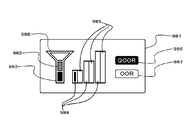
- the mobile phone is displayed on the display of FIG. 978 indicating transmission power indicates that the maximum transmission power is limited.
- 974 representing the signal intensity at the normal reception sensitivity indicates that the received signal is weak.
- 975 representing the signal strength at the lowered reception sensitivity indicates that reception is not possible. Since the user is set to “transmission power lower than normal” and communication is not possible, 976 indicating the out-of-pseudo range is highlighted.
- FIG. 8 is a variation of the icon design of FIG. 988 representing the transmission power indicates that the maximum transmission power is limited.
- 984 indicating the signal intensity at the normal reception sensitivity indicates that the received signal is weak.
- 985 representing the signal strength at the lowered reception sensitivity indicates that reception is not possible. Since the user is set to “transmission power lower than normal” and communication is not possible, 986 representing the out of pseudo range is highlighted.
- the transmission output of the mobile phone is 1 [W]
- the reception sensitivity is the maximum normal state. Thereby, a telephone call can be performed.
- the maximum transmission power is 0.1 [W] and the reception sensitivity is ⁇ 10 [dB].
- the wireless transceiver reduces the upper limit value of transmission power by operating the “operation means” 114, and determines that communication is established according to the lower limit value of transmission power. Decrease the reference value.
- the user can determine the upper limit value of the transmission power of the wireless transceiver, and the user can control the transmission power to reduce power consumption and extend the continuous operation time. Further, the influence of the radio frequency electromagnetic field on the human body can be weakened. Furthermore, the degree of “communication symmetry” breaking can be reduced.
- the “correction control signal” 352 input to the “communication establishment determination unit” 430 corresponds to the “reference value for determining communication establishment” in the invention 4.
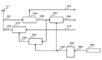
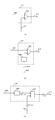
- FIG. 3 is a diagram illustrating a basic configuration of a radio transceiver according to the third embodiment.
- This wireless transmitter / receiver is a wireless transmitter / receiver having a different configuration while having the same effect as the wireless transmitter / receiver according to the second embodiment.
- the “correction control signal” 352 is simultaneously input to the “transmission power determination unit” 460 and the “communication establishment determination unit” 430, thereby transmitting power and reception sensitivity. Are linked and controlled.
- the “communication establishment determination unit” 430 compares the value of the “reception level signal” 335 with the value of the “correction control signal” 352. Yes.
- the radio transceiver according to the present embodiment is provided with a “sensitivity converter” 112 on the input side of the “communication establishment judgment unit” 440, as compared with the radio transceiver according to the second embodiment.
- the “communication establishment determination unit” 440 includes a “reference value generator” 142.
- the “sensitivity converter” 112 can be configured as shown in FIG.
- the “sensitivity converter” 112 includes an “adder” 554 that is an analog circuit.
- the “adder” 554 receives the “reception level signal” 335 and the “correction control signal” 352, adds the “reception level signal” 335 and the “correction control signal” 352, and the result of the addition is “converted” "Reception level signal” 313 is output from the output terminal.
- the “sensitivity converter” 112 can be configured as shown in FIG. In the example of FIG. 18B, the “sensitivity converter” 112 includes a “D / A converter” 569 that inputs a “correction control signal” 352 (digital signal) and performs D / A conversion, and an “adder” using an analog circuit. 554. ”.
- the “adder” 554 receives the “reception level signal” 335 and the D / A converted “correction control signal” 352, adds the “reception level signal” 335 and the “correction control signal” 352, and adds the result.
- the “converted reception level signal” 313 is output from the output terminal.
- the “sensitivity converter” 112 can be configured as shown in FIG. In the example of FIG. 18C, the “sensitivity converter” 112 includes an “A / D converter” 568 that inputs a “reception level signal” 335 and performs A / D conversion, and an “adder” 556 by a logic circuit. It is configured.
- the “adder” 556 receives the A / D converted “reception level signal” 335 and the “correction control signal” 352 (digital signal), and adds the “reception level signal” 335 and the “correction control signal” 352. Then, “the converted reception level signal” 313 (digital signal) which is the addition result is output from the output terminal.
- FIGS. 19 and 20 a circuit example of the “communication establishment determination unit” 440 is shown in FIGS. 19 and 20.
- the “communication establishment determination unit” 440 can be configured as shown in FIG.
- the “communication establishment determination unit” 440 includes a “level comparator” 141 and a “reference value generator” 142.
- the “level comparator” 141 includes a “comparator” 553 that is an analog circuit.
- “Comparator” 553 inputs “converted reception level signal” 313 from the non-inverting input terminal, inputs “reference voltage” 719 from the inverting input terminal, and outputs “communication establishment judgment signal” 343 to the output terminal. Output from.
- the “reference value generator” 142 has one end connected to the “power supply” VDD and the other end connected to the inverting input terminal of the “comparator” 553, and one end connected to the “comparator” 553. It has a “second resistance element” connected to the inverting input terminal and having the other end grounded.
- the “communication establishment determination unit” 440 can be configured as shown in FIG. In the example of FIG. 19B, the “communication establishment determination unit” 440 includes a “level comparator” 141 and a “reference value generator” 142.
- the “level comparator” 141 is the same as that in FIG.
- the “reference value generator” 142 outputs a data signal (digital signal) corresponding to the “reference voltage” 719, and D / A converts the data signal from the “CPU” 545 to obtain the “reference voltage”. And “D / A converter” 569 that outputs as 719.
- the “communication establishment determination unit” 440 can be configured as shown in FIG. In the example of FIG. 19C, the “communication establishment determination unit” 440 includes a “level comparator” 141 and a “reference value generator” 142.
- the “level comparator” 141 is the same as that in FIG.
- the “reference value generator” 142 has one end connected to the “power supply” VDD and the other end connected to the inverting input terminal of the “comparator” 553, and the cathode terminal inverted to the “comparator” 553.
- a “zener diode” 565 is connected to the input terminal and the anode terminal is grounded.
- the “communication establishment determination unit” 440 can be configured as shown in FIG.
- the “communication establishment determination unit” 440 includes a “level comparator” 141 and a “reference value generator” 142.
- the “level comparator” 141 includes a weighted “comparator” 558 by a logic circuit.
- “Comparator” 558 inputs “converted reception level signal” 313 (digital signal) from the first input terminal, “reference value” 718 from the second input terminal, and “communication establishment determination signal”. "343" is output from the output terminal.
- the “reference value generator” 142 has n + 1 “resistive elements” whose one ends are connected to the “power supply” VDD, and n + 1 pieces whose one ends are connected to the other ends of the respective “resistive elements” and whose other ends are grounded.
- the output signal from the other end of each “resistive element” corresponds to each bit of “reference value” 718 composed of n + 1 bits.
- the “communication establishment determination unit” 440 can be configured as shown in FIG.
- the “communication establishment determination unit” 440 includes a “level comparator” 141 and a “reference value generator” 142.
- the “level comparator” 141 is the same as that in FIG.
- the “reference value generator” 142 has a “first resistance element” whose one end is connected to the “power supply” VDD, a “second resistance element” whose one end is grounded, a “first resistance element”, and a “second resistance element”.
- An “A / D converter” 568 that performs A / D conversion on an output signal from the other end of the “resistive element” and outputs a “reference value” 718 is configured.
- the “communication establishment determination unit” 440 can be configured as shown in FIG.
- the “communication establishment determination unit” 440 includes a “level comparator” 141 and a “reference value generator” 142.
- the “level comparator” 141 is the same as that in FIG.
- the “reference value generator” 142 includes a “resistive element” whose one end is connected to the “power supply” VDD, a “zener diode” 565 whose anode terminal is grounded, the other end of the “resistive element”, and a “zener diode”.
- An “A / D converter” 568 that A / D-converts the output signal from the cathode terminal 565 and outputs a “reference value” 718 is configured.
- the “correction control signal” 352 output from the “control signal generation unit” 450 is input to the “transmission power determination unit” 460 and simultaneously to the “sensitivity converter” 112. Thereby, transmission power and reception sensitivity are controlled in conjunction.
- the “reception level signal” 335 output from the “reception unit” 420 is input to the “sensitivity converter” 112.
- the value of the “reception level signal” 335 is converted at a conversion rate that changes in accordance with the value of the “correction control signal” 352, and is output as a “reception level signal that has been converted” 313.
- the “converted reception level signal” 313 is input to the “communication establishment determination unit” 440 and is compared with the value generated by the “reference value generator” 142 by the “level comparator” 141.
- the “determination unit” 440 determines the state of the “communication establishment determination signal” 343.
- the “communication establishment determination signal” 343 is output in a state of either “communication establishment is possible” or “communication establishment is not possible”.
- the value generated by the “reference value generator” 142 is set by an appropriate value set by any one of the communication carrier, the device manufacturer, and the user. Alternatively, this wireless transceiver may calculate and register an optimum value. Moreover, the form which combined these two or more may be sufficient.
- the radio transceiver is a radio transceiver that allows the user to change the upper limit value of the transmission power of the radio transceiver, and changes the reception sensitivity in conjunction with it,
- the wireless transceiver can suppress problems that may occur due to a decrease in the maximum transmission power.
- the “correction control signal” 352 input to the “sensitivity converter” 112 corresponds to the “reference value for determining that communication is established” in the fourth aspect of the invention.
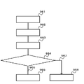
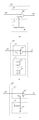
- FIG. 4 is a diagram illustrating a basic configuration of a radio transceiver according to the fourth embodiment.
- This wireless transceiver is a wireless transceiver in which “means for detecting and processing various events” 116 is added to the wireless transceiver according to the second embodiment.
- the “means for detecting and processing various events” 116 changes the transmission power and the reception sensitivity in a linked manner in a situation intended by the user or a situation registered in advance.
- Examples of the wireless transceiver according to the eleventh aspect are as follows. Only the additional part will be described.
- This wireless transceiver is equipped with the following means, and is a wireless transceiver that can change the upper limit value of transmission power by the operation performed by the user, and changes the reception sensitivity in conjunction with it.
- the wireless transceiver is capable of suppressing problems that may occur when only the maximum transmission power is reduced.
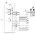
- the wireless transceiver according to the eleventh aspect of the present invention is a “control” capable of processing “operation means” 114, “operation command processing unit” 481, and “request information” 391 in the wireless transceiver according to the second embodiment.
- a signal generation unit ”480 is provided.
- control signal generator 480 stores a “CPU” 545 that performs calculation and control based on a control program, and stores a control program of the “CPU” 545 in a predetermined area in advance.
- ROM read from “ROM” 547
- RAM random access memory
- RAM random access memory
- RAM random access memory
- RAM random access memory
- data signals from “CPU” 545 are D / A It has a “D / A converter” 569 that converts and outputs a “correction control signal” 352, which can exchange data with each other via a “CPU bus” that is a signal line for transferring data. It is connected to the.
- An “operation command processing unit” 481 is connected to the “CPU bus” via an I / F (not shown), and “request information” 391 from the “operation command processing unit” 481 is a “control signal generation unit” 480. Is input.
- An “operation unit” 114 is connected to the “operation command processing unit” 481, and an “operation signal” 315 is input from the “operation unit” 114.
- a “remote operation command detection processing unit” 482 is connected to the “CPU bus” via an I / F (not shown), and “request information” 392 from the “remote operation command detection processing unit” 482 is “control signal”. Input to “Generator” 480.
- a “communication partner detection / comparison unit” 483 is connected to the “CPU bus” via an I / F (not shown), and “request information” 393 from the “communication partner detection / comparison unit” 483 is a “control signal generation unit”. ”480.
- a “wired earphone / microphone detection unit” 484 is connected to the “CPU bus” via an I / F (not shown), and “request information” 394 from the “wired earphone / microphone detection unit” 484 is “control signal”. Input to “Generator” 480.
- a “wireless earphone / microphone detector” 485 is connected to the “CPU bus” via an I / F (not shown), and “request information” 395 from the “wireless earphone / microphone detector” 485 is a “control signal”. Input to “Generator” 480.
- a “current position detection area comparison unit” 486 is connected to the “CPU bus” via an I / F (not shown), and “request information” 396 from the “current position detection area comparison unit” 486 is a “control signal”. Input to “Generator” 480.
- a “time information acquisition time zone comparison unit” 487 is connected to the “CPU bus” via an I / F (not shown), and “request information” 397 from the “time information acquisition time zone comparison unit” 487 is “ It is input to the “control signal generator” 480.
- An “emergency notification transmission detection unit” 488 is connected to the “CPU bus” via an I / F (not shown), and “request information” 398 from the “emergency notification transmission detection unit” 488 is “control signal”. Input to “Generator” 480.
- An “emergency warning reception detection unit” 489 is connected to the “CPU bus” via an I / F (not shown), and “request information” 399 from the “emergency alarm reception detection unit” 489 is “control signal generation unit”. ”480.
- “Operation command processing unit” 481 is provided on the input side of “control signal generation unit” 480.
- An “operation unit” 114 is provided on the input side of the “operation command processing unit” 481.
- “Operation signal” 315 is input from the “operation means” 114 to the “operation command processing unit” 481.
- “Request information” 391 is input from the “operation command processing unit” 481 to the “control signal generation unit” 480.
- the “operation means” 114 can be implemented by a changeover switch, a push button switch, a variable resistor, or the like.
- the “operation unit” 114 When the user performs an operation, the “operation unit” 114 generates an “operation signal” 315 and outputs it to the “operation command processing unit” 481.
- the “operation command processing unit” 481 performs processing based on the “operation signal” 315 output from the “operation means” 114 and outputs the result as “request information” 391 to the “control signal generation unit” 480.
- control signal generator 480 generates and outputs a “correction control signal” 352 based on the “request information” 391.
- reception sensitivity is also switched to “reception sensitivity lower than normal” or returned to “normal reception sensitivity”.
- the “operation command processing unit” 481 and “control signal generation unit” 480 when the user operates the “operation means” 114 of the main body so that the upper limit value of the transmission power is lower than usual.
- the operation is shown below.
- the “operation means” 114 When the user operates the “operation means” 114 of the main body, the “operation means” 114 outputs an “operation signal” 315 to the “operation command processing unit” 481.
- the “operation command processing unit” 481 processes the input “operation signal” 315 and outputs “request information” 391 for changing the upper limit value of the transmission power to the “control signal generation unit” 480.
- the “control signal generation unit” 480 outputs a “correction control signal” 352 for changing the upper limit value of transmission power and the reception sensitivity according to the input “request information” 391.
- Examples of the wireless transceiver according to the twelfth aspect are as follows. Only the additional part will be described. Since this wireless transceiver includes the following means, the upper limit value of transmission power can be changed by remote control using communication means from the outside, and the reception sensitivity can be changed in conjunction with it.
- An example of the wireless transceiver according to the twelfth aspect of the present invention is the “control signal generator” capable of processing the “remote operation command detection processor” 482 and the “request information” 392 in the wireless transceiver according to the second embodiment.
- 480 is provided.
- a circuit example of the “control signal generator” 480 is as shown in FIG.
- a “remote operation command detection processing unit” 482 is provided on the input side of the “control signal generation unit” 480.
- the “demodulation signal” 332 is input from the “reception unit” 420 to the “remote operation command detection processing unit” 482.
- “Request information” 392 is input from the “remote operation command detection processing unit” 482 to the “control signal generation unit” 480.
- the “remote operation command detection processing unit” 482 detects remote operation command information from information transmitted from the outside using communication means, creates “request information” 392 from the result, and creates a “control signal generation unit”. Output to 480.
- the “remote operation command detection processing unit” 482 compares the identification information such as the line number, IP address, URL, mail address, MAC address, etc. of the remote operation source with “pre-registered remote operation source identification information”. Then, it is determined whether remote operation is possible.
- Control signal generation unit” 480 outputs “correction control signal” 352 for changing the upper limit value of transmission power and reception sensitivity based on “request information” 392 output by “remote operation command detection processing unit” 482. .
- any one of the telecommunications carrier, the device manufacturer, and the user registers desired information as the “preliminarily registered remote operation source identification information”.
- the wireless transceiver may generate and register information.
- the form which combined these two or more may be sufficient.
- the content of “preliminarily registered remote operation source identification information” may be a line number, IP address, URL, mail address, MAC address, etc. for identifying a specific person in charge of management.
- communication including operation command information in some form can be used.
- a mail including an operation command code, a voice call signal including an operation command tone, a voice call signal including an operation command pulse, a call for calling the number of operation commands can be used.
- this wireless transceiver returns the upper limit value of the reduced transmission power to normal when making a call to a previously registered “partner in information transmission”.
- the wireless transceiver according to the thirteenth aspect of the present invention includes a “control signal generator” 480 capable of processing “communication partner detection comparator” 483 and “request information” 393 in the wireless transceiver according to the second embodiment. It is equipped with.
- a circuit example of the “control signal generator” 480 is as shown in FIG.
- a “communication partner detection / comparison unit” 483 is provided on the input side of the “control signal generation unit” 480.
- “Request information” 393 is input from “communication partner detection comparison unit” 483 to “control signal generation unit” 480.
- the “communication partner detection / comparison unit” 483 detects identification information such as a line number, an IP address, a URL, a mail address, and a MAC address of the “partner in information transmission” to start communication from now on.
- the important communication partner identification information registered in advance is compared, and “request information” 393 is output to the “control signal generator” 480 based on the result.
- the “control signal generation unit” 480 maximizes or increases the upper limit value of the transmission power based on the “request information” 393 output from the “communication partner detection / comparison unit” 483, and changes the reception sensitivity in conjunction therewith.
- a correction control signal "352 is generated and output.
- the transmission power is “transmission power lower than normal”
- the transmission power that was “low transmission power” can be returned to “normal transmission power”.
- the reception sensitivity the reception sensitivity that was “reception sensitivity lower than normal” returns to “normal reception sensitivity” in conjunction with the transmission power.
- any one of a telecommunications carrier, a device manufacturer, and a user registers the “important communication partner identification information registered in advance”.
- the wireless transmitter / receiver may register a partner who has repeatedly visited.
- the form which combined these two or more may be sufficient.
- the contents of the “pre-registered important communication partner identification information” include the police, firefighting and other public organizations that are generally highly urgent, family members that are considered to be highly important to users, specific friends, and workplaces.
- a line number, an IP address, a URL, a mail address, a MAC address, etc. for identifying a specific customer can be considered.
- Examples of the wireless transceiver according to the invention 14 are as follows. Only the additional part will be described.
- the wireless transmitter / receiver according to the fourteenth aspect of the present invention receives an incoming call from the “partner in information transmission” registered in the “pre-registered important communication partner identification information”
- the transmission power that is “transmission power lower than normal” is set to “normal transmission”. Return to "Power”.
- the reception sensitivity which is “reception sensitivity lower than normal”, returns to “normal reception sensitivity” in conjunction with the state of transmission power.
- the embodiment of the wireless transceiver of the invention 14 is implemented by the configuration provided in the embodiment of the wireless transceiver of the invention 13.
- the “communication partner detection / comparison unit” 483 detects identification information such as the line number, IP address, URL, mail address, MAC address, etc. of the incoming “partner in information transmission”.
- the "partner identification information” is compared, and "request information” 393 is output to the "control signal generator” 480 based on the result.
- the “control signal generation unit” 480 maximizes or increases the upper limit value of the transmission power based on the “request information” 393 output from the “communication partner detection / comparison unit” 483, and changes the reception sensitivity in conjunction therewith.
- a correction control signal "352 is generated and output.
- the transmission power is “transmission power lower than normal”
- the reception sensitivity that was “reception sensitivity lower than normal” returns to “normal reception sensitivity” in conjunction with the transmission power.
- the communication was terminated when the transmission power was returned to "normal transmission power” while communicating with the "partner in information transmission” registered in the "pre-registered important communication partner identification information”.
- it is about the timing of switching the transmission power to “transmission power lower than normal” again, but this may be immediately switched to “transmission power lower than normal”, or after a certain time has passed, It may be switched to “transmission power lower than normal”.
- the state of reception sensitivity at this time is switched in conjunction with the state of transmission power.
- Examples of the wireless transceiver according to the fifteenth aspect are as follows.
- the embodiment of the wireless transceiver according to the fifteenth aspect of the present invention is implemented by including the following means in the wireless transceiver according to the second embodiment, and the means detects and processes a specific event, thereby transmitting power.
- This wireless transceiver has the following means, so that when the wired earphone is connected or when the wired microphone is connected, the upper limit value of the reduced transmission power returns to normal.
- a “control signal generator” 480 capable of processing “wired earphone / microphone detector” 484 and “request information” 394 is added to the wireless transmitter according to the second embodiment. It is provided.
- a circuit example of the “control signal generator” 480 is as shown in FIG.
- a wired earphone / microphone detector” 484 is provided on the input side of the “control signal generator” 480.
- “Request information” 394 is input from the “wired earphone / microphone detection unit” 484 to the “control signal generation unit” 480.
- the “wired earphone / microphone detection unit” 484 detects that a wired earphone or a wired microphone is connected to the main body, and outputs “request information” 394 to the “control signal generation unit” 480.
- the “control signal generator” 480 maximizes or increases the upper limit value of transmission power.
- the reception sensitivity is changed in conjunction with it.
- the reception sensitivity is also “reception sensitivity lower than normal”, and the reception sensitivity returns to “normal reception sensitivity” in conjunction with the state of transmission power.
- This wireless transmitter / receiver includes the following means, so that when the wireless earphone is connected or the wireless microphone is connected, the upper limit value of the reduced transmission power returns to normal.
- the wireless transceiver according to the second embodiment is provided with a “control signal generator” 480 capable of processing “wireless earphone / microphone detector” 485 and “request information” 395. It is provided.
- a circuit example of the “control signal generator” 480 is as shown in FIG.
- a wireless earphone / microphone detector” 485 is provided on the input side of the “control signal generator” 480.
- “Request information” 395 is input from “wireless earphone / microphone detector” 485 to “control signal generator” 480.
- the “wireless earphone / microphone detection unit” 485 detects that the wireless earphone or the wireless microphone is connected to the main body, and outputs “request information” 395 to the “control signal generation unit” 480.
- the “control signal generator” 480 maximizes or increases the upper limit value of transmission power.
- the reception sensitivity is changed in conjunction with it.
- the reception sensitivity is also “reception sensitivity lower than normal”, and the reception sensitivity returns to “normal reception sensitivity” in conjunction with the state of transmission power.
- This wireless transceiver is equipped with the following means, so that when it is in a pre-registered area, the upper limit value of the reduced transmission power returns to normal.
- the wireless transceiver includes a “control signal generator” 480 capable of processing “current position detection area comparison unit” 486 and “request information” 396. It is provided.
- a circuit example of the “control signal generator” 480 is as shown in FIG.
- a “current position detection area comparison unit” 486 is provided on the input side of the “control signal generation unit” 480. “Request information” 396 is input from the “current position detection area comparison unit” 486 to the “control signal generation unit” 480.
- the “current position detection area comparison unit” 486 detects the current position information, compares it with “area information registered in advance”, and outputs “request information” 396 to the “control signal generation unit” 480.
- the “control signal generator” 480 maximizes or increases the upper limit value of transmission power.
- the reception sensitivity is changed in conjunction with it.
- the reception sensitivity is also “reception sensitivity lower than normal”, and the reception sensitivity returns to “normal reception sensitivity” in conjunction with the state of transmission power.
- the “area information registered in advance” registers any desired area information by any of the telecommunications carrier, device manufacturer, and user.
- this wireless transceiver may generate and register area information.
- the form which combined these two or more may be sufficient.
- the content of “area information registered in advance” may be the site of a medical facility.
- time information acquisition time zone comparison unit 487 will be described. Only the additional part will be described.
- This wireless transceiver is equipped with the following means, so that when it is in a pre-registered time zone, the reduced upper limit value of transmission power returns to normal.
- An example of this wireless transceiver includes a “control signal generator” 480 capable of processing “time information acquisition time zone comparison unit” 487 and “request information” 397 in the wireless transceiver according to the second embodiment. It is equipped with.
- a circuit example of the “control signal generator” 480 is as shown in FIG.
- a “time information acquisition time zone comparison unit” 487 is provided on the input side of the “control signal generation unit” 480. “Request information” 397 is input from the “time information acquisition time zone comparison unit” 487 to the “control signal generation unit” 480.
- the “time information acquisition time zone comparison unit” 487 acquires the current time information, compares it with the “previously registered time zone information”, and outputs “request information” 397 to the “control signal generation unit” 480.
- the “control signal generator” 480 maximizes or increases the upper limit value of transmission power.
- the reception sensitivity is changed in conjunction with it.
- the reception sensitivity is also “reception sensitivity lower than normal”, and the reception sensitivity returns to “normal reception sensitivity” in conjunction with the state of transmission power.
- any one of a communication carrier, a device manufacturer, and a user registers desired time zone information.
- the wireless transceiver may generate and register time zone information.
- the form which combined these two or more may be sufficient.
- the contents of “preliminarily registered time zone information” may include a commuting time zone, a commuting time zone, a time zone for attending a cram school.
- This wireless transceiver has the following means so that when the emergency alert transmission function is used, the upper limit value of the reduced transmission power returns to normal.
- the wireless transmitter / receiver includes a “control signal generator” 480 capable of processing “emergency notification transmission detector” 488 and “request information” 398. It is provided.
- a circuit example of the “control signal generator” 480 is as shown in FIG.
- An “emergency notification transmission detection unit” 488 is provided on the input side of the “control signal generation unit” 480.
- “Request information” 398 is input from the “emergency notification transmission detection unit” 488 to the “control signal generation unit” 480.
- the “emergency notification transmission detection unit” 488 detects information output from the emergency notification transmission function, and outputs “request information” 398 to the “control signal generation unit” 480.
- the “control signal generator” 480 maximizes or increases the upper limit value of transmission power.
- the reception sensitivity is changed in conjunction with it.
- the reception sensitivity is also “reception sensitivity lower than normal”, and the reception sensitivity returns to “normal reception sensitivity” in conjunction with the state of transmission power.
- the emergency notification transmission function is provided in the main body of this wireless transceiver, and inputs the line number to the emergency notification destination in the event of an emergency such as a fire or danger. It is a function that can be immediately and easily issued without any problem.
- the emergency notification destination may be a public organization such as the police or a fire department, a security company, a school-related staff member, a town association member, or a guardian.
- This wireless transceiver is equipped with the following means so that when an emergency alert signal is received, the lower limit of the transmission power that has been reduced returns to normal.
- the wireless transceiver includes a “control signal generator” 480 capable of processing “emergency warning reception detector” 489 and “request information” 399. It is a thing.
- a circuit example of the “control signal generator” 480 is as shown in FIG.
- An “emergency warning reception detection unit” 489 is provided on the input side of the “control signal generation unit” 480.
- the “demodulated signal” 332 is input from the “reception unit” 420 to the “emergency warning reception detection unit” 489.
- “Request information” 399 is input from the “emergency warning reception detection unit” 489 to the “control signal generation unit” 480.
- the “emergency warning reception detection unit” 489 detects the received emergency warning signal and outputs “request information” 399 to the “control signal generation unit” 480.
- the “control signal generator” 480 maximizes or increases the upper limit value of transmission power.
- the reception sensitivity is changed in conjunction with it.
- the reception sensitivity is also “reception sensitivity lower than normal”, and the reception sensitivity returns to “normal reception sensitivity” in conjunction with the state of transmission power.
- the emergency warning signal is a radio signal that is transmitted when the emergency notification transmission function is activated. Alternatively, it may be a radio signal transmitted based on earthquake information or tsunami information issued by an administrative organization.
- the “correction control signal” 352 input to the “communication establishment determination unit” 430 corresponds to the “reference value for determining communication establishment” in the invention 4.
- FIG. 5 is a diagram illustrating a basic configuration of a wireless transceiver according to the fifth embodiment.
- This wireless transmitter / receiver detects the current position of the wireless transmitter / receiver, and when it is in a pre-registered area, lowers the upper limit value of transmission power and lowers the reception sensitivity in conjunction with it. That is, transmission power and reception sensitivity are simultaneously reduced.
- the radio transceiver according to the present embodiment is a “control signal generator” capable of processing “current position detection area comparison unit” 486 and “request information” 396 in the radio transceiver according to the second embodiment.
- 480 is provided.
- a circuit example of the “control signal generator” 480 is as shown in FIG.
- a “current position detection area comparison unit” 486 is provided on the input side of the “control signal generation unit” 480. “Request information” 396 is input from the “current position detection area comparison unit” 486 to the “control signal generation unit” 480.
- the “current position detection area comparison unit” 486 detects the current position where the wireless transceiver is placed, and determines whether the position is inside or outside the area indicated by “area information registered in advance”. Thereafter, it is determined whether the transmission power state should be switched, and the result is output as “request information” 396 to the “control signal generator” 480.
- the “control signal generator” 480 generates and outputs a “correction control signal” 352 based on the “request information” 396.
- the “correction control signal” 352 is output to the “transmission power determination unit” 460 and simultaneously to the “communication establishment determination unit” 430.
- the “transmission power determination unit” 460 and the “communication establishment determination unit” 430 are controlled by a single operation.
- the transmission power can be switched to “transmission power lower than normal” or returned to “normal transmission power” according to the position of the radio transceiver, and linked to the switching of the transmission power. Accordingly, the reception sensitivity is switched to “reception sensitivity lower than normal” or returned to “normal reception sensitivity”.
- the “correction control signal” 352 input to the “communication establishment determination unit” 430 corresponds to the “reference value for determining communication establishment” in the invention 4.
- the wireless terminal In a hospital ward, if a pico cell is installed, it is possible to reduce the transmission power for the wireless terminal that the pico cell has designated as “the partner of wireless transmission / reception”. For example, the wireless terminal is near the window, If the radio wave received from a wireless base station outside the site is stronger, the wireless terminal communicates with high transmission power according to the radio wave received from the wireless base station, and as a result, it fails to suppress the transmission power. There is a fear.
- the transmission output is transmitted within the hospital site. It becomes possible to suppress it reliably.
- the picocell has the role of a radio base station in a mobile communication system, which is particularly small for indoor installation that has low transmission power and ensures radio transmission and reception in a very narrow limited area. It is a radio base station.
- radio transceiver according to the first to fifth embodiments. This is because when the user changes the transmission power, at the same time, the “reception system” is also changed in some way to suppress the harmful effects that may occur when the transmission power is changed. It can prevent confusion.
- the radio transceiver according to the first to fifth embodiments has been described as an example applied to a radio terminal in a mobile communication system, but the present invention is a one-to-one communication such as a transceiver. It can also be implemented in this relationship.
- the intensity of the received radio wave is measured, the transmission power is controlled based on this, and a state where good communication can be expected is determined.
- the error rate of the received data is measured, the reception sensitivity is controlled based on the error rate, and good communication is expected. You may judge the state which can be done.
- the reception sensitivity is reduced according to the upper limit value of the transmission power reduced by the operation of the “operation unit” 114.
- the present invention is not limited to this.
- the allowable value of the error rate of the received data can be reduced according to the upper limit value of the transmission power reduced by the operation of the “operation means” 114.
- the “normal transmission power” state when the error rate of the received data is equal to or lower than the first threshold (error rate allowable value), it is determined that communication is established, whereas “transmission lower than normal” In the “power” state, it is determined that communication is established when the error rate of the received data is equal to or lower than a second threshold value (allowable error rate) lower than the first threshold value.
- transmission control and reception control are performed by a single operation, but also (1) transmission control and reception control are performed by a plurality of operations.
- Configuration (2) Configuration in which transmission control is performed by the first operation (one or a plurality of operations) and then reception control is performed by the second operation (one or a plurality of operations), (3) First operation (1 Or a configuration in which transmission control is performed by a second operation (one or a plurality of operations) after performing reception control by a plurality of operations), or (4) only transmission control is performed by a predetermined operation (one or a plurality of operations).
- reception control is performed so that the reception range matches the transmission range or the mismatched portion becomes small regardless of the operation.
- the predetermined operation that triggers transmission control or reception control may be common to an operation that activates another function. For example, if the operation is common to the operation for increasing or decreasing the call volume, the upper limit value of the transmission power can be decreased along with the operation for decreasing the call volume.
- the wireless base station is notified of the reception status of the wireless transceiver, for example, the wireless base station performs wireless transmission / reception.
- the reception performance is reduced or the reception performance is reduced in accordance with the upper limit value of the transmission power reduced by the operation of the “operation means” 114. In this case, it is possible to notify the communication partner of the reception status in the case of failure.
- the reception performance of the wireless transceiver may or may not be lowered as in the first to fifth embodiments. If the reception performance is actually reduced by the wireless transceiver, the notification content will be the reception status when the reception performance is reduced according to the reduced upper limit of transmission power, and the wireless transceiver will not degrade the reception performance.
- the notification content is a reception state when the reception performance is lowered according to the upper limit value of the reduced transmission power.
- the reception status is, for example, “Current reception strength is ** [dB]” in analog communication, and “Current error rate is **” in digital communication. It becomes. However, it is sufficient to include only the information “**” in the transmission signal.
- the reception sensitivity is configured to be reduced to a constant value 813 regardless of the propagation loss.
- the present invention is not limited to this, and for example, it may be configured to gradually decrease from the maximum receiving sensitivity 805 to a constant value 813 as the propagation loss increases. The same applies to the second to fifth embodiments and the modifications thereof.
- the wireless transceiver decreases the upper limit value of the transmission power by operating the “operation unit” 114, and increases the reception sensitivity according to the lower limit value of the transmission power.
- the “operation means” 114 is operated when the current transmission power is the maximum transmission power 804 in FIG. 22, the transmission power required for communication with the radio base station (maximum transmission power 804) It can be said that a lower value (constant value 811) is set as the upper limit value to suppress transmission power.
- a lower value constant value 811
Abstract
Priority Applications (2)
| Application Number | Priority Date | Filing Date | Title |
|---|---|---|---|
| JP2011553221A JPWO2012057094A1 (ja) | 2010-10-25 | 2011-10-24 | 通信装置 |
| US13/881,404 US9198127B2 (en) | 2010-10-25 | 2011-10-24 | Communication device |
Applications Claiming Priority (2)
| Application Number | Priority Date | Filing Date | Title |
|---|---|---|---|
| JP2010238583 | 2010-10-25 | ||
| JP2010-238583 | 2010-10-25 |
Publications (1)
| Publication Number | Publication Date |
|---|---|
| WO2012057094A1 true WO2012057094A1 (fr) | 2012-05-03 |
Family
ID=45993802
Family Applications (1)
| Application Number | Title | Priority Date | Filing Date |
|---|---|---|---|
| PCT/JP2011/074464 WO2012057094A1 (fr) | 2010-10-25 | 2011-10-24 | Dispositif de communication |
Country Status (3)
| Country | Link |
|---|---|
| US (1) | US9198127B2 (fr) |
| JP (8) | JPWO2012057094A1 (fr) |
| WO (1) | WO2012057094A1 (fr) |
Cited By (1)
| Publication number | Priority date | Publication date | Assignee | Title |
|---|---|---|---|---|
| JP2017135540A (ja) * | 2016-01-27 | 2017-08-03 | 京セラ株式会社 | 電子機器、制御装置、制御プログラム及び電子機器の動作方法 |
Families Citing this family (184)
| Publication number | Priority date | Publication date | Assignee | Title |
|---|---|---|---|---|
| US9948135B2 (en) | 2015-09-22 | 2018-04-17 | Energous Corporation | Systems and methods for identifying sensitive objects in a wireless charging transmission field |
| US9923386B1 (en) | 2012-07-06 | 2018-03-20 | Energous Corporation | Systems and methods for wireless power transmission by modifying a number of antenna elements used to transmit power waves to a receiver |
| US10063064B1 (en) | 2014-05-23 | 2018-08-28 | Energous Corporation | System and method for generating a power receiver identifier in a wireless power network |
| US10206185B2 (en) | 2013-05-10 | 2019-02-12 | Energous Corporation | System and methods for wireless power transmission to an electronic device in accordance with user-defined restrictions |
| US9252628B2 (en) | 2013-05-10 | 2016-02-02 | Energous Corporation | Laptop computer as a transmitter for wireless charging |
| US9847677B1 (en) | 2013-10-10 | 2017-12-19 | Energous Corporation | Wireless charging and powering of healthcare gadgets and sensors |
| US10141768B2 (en) | 2013-06-03 | 2018-11-27 | Energous Corporation | Systems and methods for maximizing wireless power transfer efficiency by instructing a user to change a receiver device's position |
| US10186913B2 (en) | 2012-07-06 | 2019-01-22 | Energous Corporation | System and methods for pocket-forming based on constructive and destructive interferences to power one or more wireless power receivers using a wireless power transmitter including a plurality of antennas |
| US9939864B1 (en) | 2014-08-21 | 2018-04-10 | Energous Corporation | System and method to control a wireless power transmission system by configuration of wireless power transmission control parameters |
| US10211674B1 (en) | 2013-06-12 | 2019-02-19 | Energous Corporation | Wireless charging using selected reflectors |
| US9124125B2 (en) | 2013-05-10 | 2015-09-01 | Energous Corporation | Wireless power transmission with selective range |
| US10992185B2 (en) | 2012-07-06 | 2021-04-27 | Energous Corporation | Systems and methods of using electromagnetic waves to wirelessly deliver power to game controllers |
| US9941707B1 (en) | 2013-07-19 | 2018-04-10 | Energous Corporation | Home base station for multiple room coverage with multiple transmitters |
| US10211680B2 (en) | 2013-07-19 | 2019-02-19 | Energous Corporation | Method for 3 dimensional pocket-forming |
| US10270261B2 (en) | 2015-09-16 | 2019-04-23 | Energous Corporation | Systems and methods of object detection in wireless power charging systems |
| US9859797B1 (en) | 2014-05-07 | 2018-01-02 | Energous Corporation | Synchronous rectifier design for wireless power receiver |
| US9876379B1 (en) | 2013-07-11 | 2018-01-23 | Energous Corporation | Wireless charging and powering of electronic devices in a vehicle |
| US10230266B1 (en) | 2014-02-06 | 2019-03-12 | Energous Corporation | Wireless power receivers that communicate status data indicating wireless power transmission effectiveness with a transmitter using a built-in communications component of a mobile device, and methods of use thereof |
| US10243414B1 (en) | 2014-05-07 | 2019-03-26 | Energous Corporation | Wearable device with wireless power and payload receiver |
| US10263432B1 (en) | 2013-06-25 | 2019-04-16 | Energous Corporation | Multi-mode transmitter with an antenna array for delivering wireless power and providing Wi-Fi access |
| US9891669B2 (en) | 2014-08-21 | 2018-02-13 | Energous Corporation | Systems and methods for a configuration web service to provide configuration of a wireless power transmitter within a wireless power transmission system |
| US10224982B1 (en) | 2013-07-11 | 2019-03-05 | Energous Corporation | Wireless power transmitters for transmitting wireless power and tracking whether wireless power receivers are within authorized locations |
| US9843213B2 (en) | 2013-08-06 | 2017-12-12 | Energous Corporation | Social power sharing for mobile devices based on pocket-forming |
| US10103582B2 (en) | 2012-07-06 | 2018-10-16 | Energous Corporation | Transmitters for wireless power transmission |
| US9912199B2 (en) | 2012-07-06 | 2018-03-06 | Energous Corporation | Receivers for wireless power transmission |
| US10291066B1 (en) | 2014-05-07 | 2019-05-14 | Energous Corporation | Power transmission control systems and methods |
| US9847679B2 (en) | 2014-05-07 | 2017-12-19 | Energous Corporation | System and method for controlling communication between wireless power transmitter managers |
| US10128693B2 (en) | 2014-07-14 | 2018-11-13 | Energous Corporation | System and method for providing health safety in a wireless power transmission system |
| US9143000B2 (en) | 2012-07-06 | 2015-09-22 | Energous Corporation | Portable wireless charging pad |
| US10063105B2 (en) | 2013-07-11 | 2018-08-28 | Energous Corporation | Proximity transmitters for wireless power charging systems |
| US9893768B2 (en) | 2012-07-06 | 2018-02-13 | Energous Corporation | Methodology for multiple pocket-forming |
| US9831718B2 (en) | 2013-07-25 | 2017-11-28 | Energous Corporation | TV with integrated wireless power transmitter |
| US9876648B2 (en) | 2014-08-21 | 2018-01-23 | Energous Corporation | System and method to control a wireless power transmission system by configuration of wireless power transmission control parameters |
| US10141791B2 (en) | 2014-05-07 | 2018-11-27 | Energous Corporation | Systems and methods for controlling communications during wireless transmission of power using application programming interfaces |
| US9893554B2 (en) | 2014-07-14 | 2018-02-13 | Energous Corporation | System and method for providing health safety in a wireless power transmission system |
| US10211682B2 (en) | 2014-05-07 | 2019-02-19 | Energous Corporation | Systems and methods for controlling operation of a transmitter of a wireless power network based on user instructions received from an authenticated computing device powered or charged by a receiver of the wireless power network |
| US9882430B1 (en) | 2014-05-07 | 2018-01-30 | Energous Corporation | Cluster management of transmitters in a wireless power transmission system |
| US10124754B1 (en) | 2013-07-19 | 2018-11-13 | Energous Corporation | Wireless charging and powering of electronic sensors in a vehicle |
| US9867062B1 (en) | 2014-07-21 | 2018-01-09 | Energous Corporation | System and methods for using a remote server to authorize a receiving device that has requested wireless power and to determine whether another receiving device should request wireless power in a wireless power transmission system |
| US9966765B1 (en) | 2013-06-25 | 2018-05-08 | Energous Corporation | Multi-mode transmitter |
| US10090886B1 (en) | 2014-07-14 | 2018-10-02 | Energous Corporation | System and method for enabling automatic charging schedules in a wireless power network to one or more devices |
| US9893555B1 (en) | 2013-10-10 | 2018-02-13 | Energous Corporation | Wireless charging of tools using a toolbox transmitter |
| US9368020B1 (en) | 2013-05-10 | 2016-06-14 | Energous Corporation | Off-premises alert system and method for wireless power receivers in a wireless power network |
| US9838083B2 (en) | 2014-07-21 | 2017-12-05 | Energous Corporation | Systems and methods for communication with remote management systems |
| US10291055B1 (en) | 2014-12-29 | 2019-05-14 | Energous Corporation | Systems and methods for controlling far-field wireless power transmission based on battery power levels of a receiving device |
| US10223717B1 (en) | 2014-05-23 | 2019-03-05 | Energous Corporation | Systems and methods for payment-based authorization of wireless power transmission service |
| US9871398B1 (en) | 2013-07-01 | 2018-01-16 | Energous Corporation | Hybrid charging method for wireless power transmission based on pocket-forming |
| US10965164B2 (en) | 2012-07-06 | 2021-03-30 | Energous Corporation | Systems and methods of wirelessly delivering power to a receiver device |
| US20150326070A1 (en) | 2014-05-07 | 2015-11-12 | Energous Corporation | Methods and Systems for Maximum Power Point Transfer in Receivers |
| US9853458B1 (en) | 2014-05-07 | 2017-12-26 | Energous Corporation | Systems and methods for device and power receiver pairing |
| US9812890B1 (en) | 2013-07-11 | 2017-11-07 | Energous Corporation | Portable wireless charging pad |
| US10090699B1 (en) | 2013-11-01 | 2018-10-02 | Energous Corporation | Wireless powered house |
| US9906065B2 (en) | 2012-07-06 | 2018-02-27 | Energous Corporation | Systems and methods of transmitting power transmission waves based on signals received at first and second subsets of a transmitter's antenna array |
| US10205239B1 (en) | 2014-05-07 | 2019-02-12 | Energous Corporation | Compact PIFA antenna |
| US10128699B2 (en) | 2014-07-14 | 2018-11-13 | Energous Corporation | Systems and methods of providing wireless power using receiver device sensor inputs |
| US9973021B2 (en) | 2012-07-06 | 2018-05-15 | Energous Corporation | Receivers for wireless power transmission |
| US10148097B1 (en) | 2013-11-08 | 2018-12-04 | Energous Corporation | Systems and methods for using a predetermined number of communication channels of a wireless power transmitter to communicate with different wireless power receivers |
| US10381880B2 (en) | 2014-07-21 | 2019-08-13 | Energous Corporation | Integrated antenna structure arrays for wireless power transmission |
| US10063106B2 (en) | 2014-05-23 | 2018-08-28 | Energous Corporation | System and method for a self-system analysis in a wireless power transmission network |
| US9853692B1 (en) | 2014-05-23 | 2017-12-26 | Energous Corporation | Systems and methods for wireless power transmission |
| US9941747B2 (en) * | 2014-07-14 | 2018-04-10 | Energous Corporation | System and method for manually selecting and deselecting devices to charge in a wireless power network |
| US9899873B2 (en) | 2014-05-23 | 2018-02-20 | Energous Corporation | System and method for generating a power receiver identifier in a wireless power network |
| US9787103B1 (en) | 2013-08-06 | 2017-10-10 | Energous Corporation | Systems and methods for wirelessly delivering power to electronic devices that are unable to communicate with a transmitter |
| US10050462B1 (en) | 2013-08-06 | 2018-08-14 | Energous Corporation | Social power sharing for mobile devices based on pocket-forming |
| US9793758B2 (en) | 2014-05-23 | 2017-10-17 | Energous Corporation | Enhanced transmitter using frequency control for wireless power transmission |
| US9876394B1 (en) | 2014-05-07 | 2018-01-23 | Energous Corporation | Boost-charger-boost system for enhanced power delivery |
| US10439448B2 (en) | 2014-08-21 | 2019-10-08 | Energous Corporation | Systems and methods for automatically testing the communication between wireless power transmitter and wireless power receiver |
| US20140008993A1 (en) | 2012-07-06 | 2014-01-09 | DvineWave Inc. | Methodology for pocket-forming |
| US9991741B1 (en) | 2014-07-14 | 2018-06-05 | Energous Corporation | System for tracking and reporting status and usage information in a wireless power management system |
| US10075008B1 (en) | 2014-07-14 | 2018-09-11 | Energous Corporation | Systems and methods for manually adjusting when receiving electronic devices are scheduled to receive wirelessly delivered power from a wireless power transmitter in a wireless power network |
| US9438045B1 (en) | 2013-05-10 | 2016-09-06 | Energous Corporation | Methods and systems for maximum power point transfer in receivers |
| US9887584B1 (en) | 2014-08-21 | 2018-02-06 | Energous Corporation | Systems and methods for a configuration web service to provide configuration of a wireless power transmitter within a wireless power transmission system |
| US10992187B2 (en) | 2012-07-06 | 2021-04-27 | Energous Corporation | System and methods of using electromagnetic waves to wirelessly deliver power to electronic devices |
| US9882427B2 (en) | 2013-05-10 | 2018-01-30 | Energous Corporation | Wireless power delivery using a base station to control operations of a plurality of wireless power transmitters |
| US9825674B1 (en) | 2014-05-23 | 2017-11-21 | Energous Corporation | Enhanced transmitter that selects configurations of antenna elements for performing wireless power transmission and receiving functions |
| US9806564B2 (en) | 2014-05-07 | 2017-10-31 | Energous Corporation | Integrated rectifier and boost converter for wireless power transmission |
| US10199835B2 (en) | 2015-12-29 | 2019-02-05 | Energous Corporation | Radar motion detection using stepped frequency in wireless power transmission system |
| US10038337B1 (en) | 2013-09-16 | 2018-07-31 | Energous Corporation | Wireless power supply for rescue devices |
| US9859757B1 (en) | 2013-07-25 | 2018-01-02 | Energous Corporation | Antenna tile arrangements in electronic device enclosures |
| US10193396B1 (en) | 2014-05-07 | 2019-01-29 | Energous Corporation | Cluster management of transmitters in a wireless power transmission system |
| US9900057B2 (en) | 2012-07-06 | 2018-02-20 | Energous Corporation | Systems and methods for assigning groups of antenas of a wireless power transmitter to different wireless power receivers, and determining effective phases to use for wirelessly transmitting power using the assigned groups of antennas |
| US11502551B2 (en) | 2012-07-06 | 2022-11-15 | Energous Corporation | Wirelessly charging multiple wireless-power receivers using different subsets of an antenna array to focus energy at different locations |
| US10008889B2 (en) | 2014-08-21 | 2018-06-26 | Energous Corporation | Method for automatically testing the operational status of a wireless power receiver in a wireless power transmission system |
| US10199849B1 (en) | 2014-08-21 | 2019-02-05 | Energous Corporation | Method for automatically testing the operational status of a wireless power receiver in a wireless power transmission system |
| US10312715B2 (en) | 2015-09-16 | 2019-06-04 | Energous Corporation | Systems and methods for wireless power charging |
| US10224758B2 (en) | 2013-05-10 | 2019-03-05 | Energous Corporation | Wireless powering of electronic devices with selective delivery range |
| US9887739B2 (en) | 2012-07-06 | 2018-02-06 | Energous Corporation | Systems and methods for wireless power transmission by comparing voltage levels associated with power waves transmitted by antennas of a plurality of antennas of a transmitter to determine appropriate phase adjustments for the power waves |
| US9859756B2 (en) | 2012-07-06 | 2018-01-02 | Energous Corporation | Transmittersand methods for adjusting wireless power transmission based on information from receivers |
| US9954374B1 (en) | 2014-05-23 | 2018-04-24 | Energous Corporation | System and method for self-system analysis for detecting a fault in a wireless power transmission Network |
| US9824815B2 (en) | 2013-05-10 | 2017-11-21 | Energous Corporation | Wireless charging and powering of healthcare gadgets and sensors |
| US9843201B1 (en) | 2012-07-06 | 2017-12-12 | Energous Corporation | Wireless power transmitter that selects antenna sets for transmitting wireless power to a receiver based on location of the receiver, and methods of use thereof |
| US9899861B1 (en) | 2013-10-10 | 2018-02-20 | Energous Corporation | Wireless charging methods and systems for game controllers, based on pocket-forming |
| US10218227B2 (en) | 2014-05-07 | 2019-02-26 | Energous Corporation | Compact PIFA antenna |
| US9941754B2 (en) | 2012-07-06 | 2018-04-10 | Energous Corporation | Wireless power transmission with selective range |
| US10256657B2 (en) | 2015-12-24 | 2019-04-09 | Energous Corporation | Antenna having coaxial structure for near field wireless power charging |
| US9843763B2 (en) | 2013-05-10 | 2017-12-12 | Energous Corporation | TV system with wireless power transmitter |
| US9866279B2 (en) | 2013-05-10 | 2018-01-09 | Energous Corporation | Systems and methods for selecting which power transmitter should deliver wireless power to a receiving device in a wireless power delivery network |
| US9538382B2 (en) | 2013-05-10 | 2017-01-03 | Energous Corporation | System and method for smart registration of wireless power receivers in a wireless power network |
| US9537357B2 (en) | 2013-05-10 | 2017-01-03 | Energous Corporation | Wireless sound charging methods and systems for game controllers, based on pocket-forming |
| US9419443B2 (en) | 2013-05-10 | 2016-08-16 | Energous Corporation | Transducer sound arrangement for pocket-forming |
| US9819230B2 (en) | 2014-05-07 | 2017-11-14 | Energous Corporation | Enhanced receiver for wireless power transmission |
| US10103552B1 (en) | 2013-06-03 | 2018-10-16 | Energous Corporation | Protocols for authenticated wireless power transmission |
| US10003211B1 (en) | 2013-06-17 | 2018-06-19 | Energous Corporation | Battery life of portable electronic devices |
| US10021523B2 (en) | 2013-07-11 | 2018-07-10 | Energous Corporation | Proximity transmitters for wireless power charging systems |
| US9979440B1 (en) | 2013-07-25 | 2018-05-22 | Energous Corporation | Antenna tile arrangements configured to operate as one functional unit |
| US9935482B1 (en) | 2014-02-06 | 2018-04-03 | Energous Corporation | Wireless power transmitters that transmit at determined times based on power availability and consumption at a receiving mobile device |
| US10075017B2 (en) | 2014-02-06 | 2018-09-11 | Energous Corporation | External or internal wireless power receiver with spaced-apart antenna elements for charging or powering mobile devices using wirelessly delivered power |
| US10158257B2 (en) | 2014-05-01 | 2018-12-18 | Energous Corporation | System and methods for using sound waves to wirelessly deliver power to electronic devices |
| US9966784B2 (en) | 2014-06-03 | 2018-05-08 | Energous Corporation | Systems and methods for extending battery life of portable electronic devices charged by sound |
| US10153645B1 (en) | 2014-05-07 | 2018-12-11 | Energous Corporation | Systems and methods for designating a master power transmitter in a cluster of wireless power transmitters |
| US9800172B1 (en) | 2014-05-07 | 2017-10-24 | Energous Corporation | Integrated rectifier and boost converter for boosting voltage received from wireless power transmission waves |
| US10170917B1 (en) | 2014-05-07 | 2019-01-01 | Energous Corporation | Systems and methods for managing and controlling a wireless power network by establishing time intervals during which receivers communicate with a transmitter |
| US10153653B1 (en) | 2014-05-07 | 2018-12-11 | Energous Corporation | Systems and methods for using application programming interfaces to control communications between a transmitter and a receiver |
| US9973008B1 (en) | 2014-05-07 | 2018-05-15 | Energous Corporation | Wireless power receiver with boost converters directly coupled to a storage element |
| US9876536B1 (en) | 2014-05-23 | 2018-01-23 | Energous Corporation | Systems and methods for assigning groups of antennas to transmit wireless power to different wireless power receivers |
| US9871301B2 (en) | 2014-07-21 | 2018-01-16 | Energous Corporation | Integrated miniature PIFA with artificial magnetic conductor metamaterials |
| US10116143B1 (en) | 2014-07-21 | 2018-10-30 | Energous Corporation | Integrated antenna arrays for wireless power transmission |
| US10068703B1 (en) | 2014-07-21 | 2018-09-04 | Energous Corporation | Integrated miniature PIFA with artificial magnetic conductor metamaterials |
| US9917477B1 (en) | 2014-08-21 | 2018-03-13 | Energous Corporation | Systems and methods for automatically testing the communication between power transmitter and wireless receiver |
| US9965009B1 (en) | 2014-08-21 | 2018-05-08 | Energous Corporation | Systems and methods for assigning a power receiver to individual power transmitters based on location of the power receiver |
| FR3025966A1 (fr) * | 2014-09-11 | 2016-03-18 | Orange | Procede d'utilisation de valeurs seuils de signaux wifi et station wifi associee |
| US10122415B2 (en) | 2014-12-27 | 2018-11-06 | Energous Corporation | Systems and methods for assigning a set of antennas of a wireless power transmitter to a wireless power receiver based on a location of the wireless power receiver |
| US9893535B2 (en) | 2015-02-13 | 2018-02-13 | Energous Corporation | Systems and methods for determining optimal charging positions to maximize efficiency of power received from wirelessly delivered sound wave energy |
| US10523033B2 (en) | 2015-09-15 | 2019-12-31 | Energous Corporation | Receiver devices configured to determine location within a transmission field |
| US9906275B2 (en) | 2015-09-15 | 2018-02-27 | Energous Corporation | Identifying receivers in a wireless charging transmission field |
| US10008875B1 (en) | 2015-09-16 | 2018-06-26 | Energous Corporation | Wireless power transmitter configured to transmit power waves to a predicted location of a moving wireless power receiver |
| US11710321B2 (en) | 2015-09-16 | 2023-07-25 | Energous Corporation | Systems and methods of object detection in wireless power charging systems |
| US10211685B2 (en) | 2015-09-16 | 2019-02-19 | Energous Corporation | Systems and methods for real or near real time wireless communications between a wireless power transmitter and a wireless power receiver |
| US10778041B2 (en) | 2015-09-16 | 2020-09-15 | Energous Corporation | Systems and methods for generating power waves in a wireless power transmission system |
| US9893538B1 (en) | 2015-09-16 | 2018-02-13 | Energous Corporation | Systems and methods of object detection in wireless power charging systems |
| US10158259B1 (en) | 2015-09-16 | 2018-12-18 | Energous Corporation | Systems and methods for identifying receivers in a transmission field by transmitting exploratory power waves towards different segments of a transmission field |
| US10199850B2 (en) | 2015-09-16 | 2019-02-05 | Energous Corporation | Systems and methods for wirelessly transmitting power from a transmitter to a receiver by determining refined locations of the receiver in a segmented transmission field associated with the transmitter |
| US9941752B2 (en) | 2015-09-16 | 2018-04-10 | Energous Corporation | Systems and methods of object detection in wireless power charging systems |
| US10186893B2 (en) | 2015-09-16 | 2019-01-22 | Energous Corporation | Systems and methods for real time or near real time wireless communications between a wireless power transmitter and a wireless power receiver |
| US9871387B1 (en) | 2015-09-16 | 2018-01-16 | Energous Corporation | Systems and methods of object detection using one or more video cameras in wireless power charging systems |
| US10135295B2 (en) | 2015-09-22 | 2018-11-20 | Energous Corporation | Systems and methods for nullifying energy levels for wireless power transmission waves |
| US10153660B1 (en) | 2015-09-22 | 2018-12-11 | Energous Corporation | Systems and methods for preconfiguring sensor data for wireless charging systems |
| US10020678B1 (en) | 2015-09-22 | 2018-07-10 | Energous Corporation | Systems and methods for selecting antennas to generate and transmit power transmission waves |
| US10033222B1 (en) | 2015-09-22 | 2018-07-24 | Energous Corporation | Systems and methods for determining and generating a waveform for wireless power transmission waves |
| US10128686B1 (en) | 2015-09-22 | 2018-11-13 | Energous Corporation | Systems and methods for identifying receiver locations using sensor technologies |
| US10135294B1 (en) | 2015-09-22 | 2018-11-20 | Energous Corporation | Systems and methods for preconfiguring transmission devices for power wave transmissions based on location data of one or more receivers |
| US10027168B2 (en) | 2015-09-22 | 2018-07-17 | Energous Corporation | Systems and methods for generating and transmitting wireless power transmission waves using antennas having a spacing that is selected by the transmitter |
| US10050470B1 (en) | 2015-09-22 | 2018-08-14 | Energous Corporation | Wireless power transmission device having antennas oriented in three dimensions |
| US10333332B1 (en) | 2015-10-13 | 2019-06-25 | Energous Corporation | Cross-polarized dipole antenna |
| US10734717B2 (en) | 2015-10-13 | 2020-08-04 | Energous Corporation | 3D ceramic mold antenna |
| US9899744B1 (en) | 2015-10-28 | 2018-02-20 | Energous Corporation | Antenna for wireless charging systems |
| US9853485B2 (en) | 2015-10-28 | 2017-12-26 | Energous Corporation | Antenna for wireless charging systems |
| US10063108B1 (en) | 2015-11-02 | 2018-08-28 | Energous Corporation | Stamped three-dimensional antenna |
| US10135112B1 (en) | 2015-11-02 | 2018-11-20 | Energous Corporation | 3D antenna mount |
| US10027180B1 (en) | 2015-11-02 | 2018-07-17 | Energous Corporation | 3D triple linear antenna that acts as heat sink |
| US10027159B2 (en) | 2015-12-24 | 2018-07-17 | Energous Corporation | Antenna for transmitting wireless power signals |
| US10141771B1 (en) | 2015-12-24 | 2018-11-27 | Energous Corporation | Near field transmitters with contact points for wireless power charging |
| US10320446B2 (en) | 2015-12-24 | 2019-06-11 | Energous Corporation | Miniaturized highly-efficient designs for near-field power transfer system |
| US11863001B2 (en) | 2015-12-24 | 2024-01-02 | Energous Corporation | Near-field antenna for wireless power transmission with antenna elements that follow meandering patterns |
| US10079515B2 (en) | 2016-12-12 | 2018-09-18 | Energous Corporation | Near-field RF charging pad with multi-band antenna element with adaptive loading to efficiently charge an electronic device at any position on the pad |
| US10256677B2 (en) | 2016-12-12 | 2019-04-09 | Energous Corporation | Near-field RF charging pad with adaptive loading to efficiently charge an electronic device at any position on the pad |
| US10038332B1 (en) | 2015-12-24 | 2018-07-31 | Energous Corporation | Systems and methods of wireless power charging through multiple receiving devices |
| US10008886B2 (en) | 2015-12-29 | 2018-06-26 | Energous Corporation | Modular antennas with heat sinks in wireless power transmission systems |
| KR102255878B1 (ko) | 2016-08-31 | 2021-05-24 | 후아웨이 테크놀러지 컴퍼니 리미티드 | 포스 터치 기반 통신 강화 방법 및 단말 |
| US10923954B2 (en) | 2016-11-03 | 2021-02-16 | Energous Corporation | Wireless power receiver with a synchronous rectifier |
| CN110235337A (zh) | 2016-12-12 | 2019-09-13 | 艾诺格思公司 | 选择性地激活近场充电垫的天线区域以最大化所传递无线功率的方法 |
| US10389161B2 (en) | 2017-03-15 | 2019-08-20 | Energous Corporation | Surface mount dielectric antennas for wireless power transmitters |
| US10439442B2 (en) | 2017-01-24 | 2019-10-08 | Energous Corporation | Microstrip antennas for wireless power transmitters |
| US10680319B2 (en) | 2017-01-06 | 2020-06-09 | Energous Corporation | Devices and methods for reducing mutual coupling effects in wireless power transmission systems |
| WO2018183892A1 (fr) | 2017-03-30 | 2018-10-04 | Energous Corporation | Antennes plates ayant deux fréquences de résonance ou plus destinées à être utilisées dans des systèmes de transmission de puissance sans fil |
| US10511097B2 (en) | 2017-05-12 | 2019-12-17 | Energous Corporation | Near-field antennas for accumulating energy at a near-field distance with minimal far-field gain |
| US11462949B2 (en) | 2017-05-16 | 2022-10-04 | Wireless electrical Grid LAN, WiGL Inc | Wireless charging method and system |
| US10848853B2 (en) | 2017-06-23 | 2020-11-24 | Energous Corporation | Systems, methods, and devices for utilizing a wire of a sound-producing device as an antenna for receipt of wirelessly delivered power |
| US10122219B1 (en) | 2017-10-10 | 2018-11-06 | Energous Corporation | Systems, methods, and devices for using a battery as a antenna for receiving wirelessly delivered power from radio frequency power waves |
| US11342798B2 (en) | 2017-10-30 | 2022-05-24 | Energous Corporation | Systems and methods for managing coexistence of wireless-power signals and data signals operating in a same frequency band |
| US10615647B2 (en) | 2018-02-02 | 2020-04-07 | Energous Corporation | Systems and methods for detecting wireless power receivers and other objects at a near-field charging pad |
| US11159057B2 (en) | 2018-03-14 | 2021-10-26 | Energous Corporation | Loop antennas with selectively-activated feeds to control propagation patterns of wireless power signals |
| US11515732B2 (en) | 2018-06-25 | 2022-11-29 | Energous Corporation | Power wave transmission techniques to focus wirelessly delivered power at a receiving device |
| US11437735B2 (en) | 2018-11-14 | 2022-09-06 | Energous Corporation | Systems for receiving electromagnetic energy using antennas that are minimally affected by the presence of the human body |
| KR20210117283A (ko) | 2019-01-28 | 2021-09-28 | 에너저스 코포레이션 | 무선 전력 전송을 위한 소형 안테나에 대한 시스템들 및 방법들 |
| CN113661660B (zh) | 2019-02-06 | 2023-01-24 | 艾诺格思公司 | 估计最佳相位的方法、无线电力发射设备及存储介质 |
| WO2021055898A1 (fr) | 2019-09-20 | 2021-03-25 | Energous Corporation | Systèmes et procédés de détection d'objet étranger basée sur l'apprentissage automatique pour transmission de puissance sans fil |
| WO2021055900A1 (fr) | 2019-09-20 | 2021-03-25 | Energous Corporation | Classification et détection d'objets étrangers à l'aide d'un circuit intégré de dispositif de commande d'amplificateur de puissance dans des systèmes de transmission de puissance sans fil |
| US11381118B2 (en) | 2019-09-20 | 2022-07-05 | Energous Corporation | Systems and methods for machine learning based foreign object detection for wireless power transmission |
| EP4032166A4 (fr) | 2019-09-20 | 2023-10-18 | Energous Corporation | Systèmes et procédés de protection de récepteurs de puissance sans fil à l'aide de multiples redresseurs et établissement de communications en bande à l'aide de multiples redresseurs |
| EP4073905A4 (fr) | 2019-12-13 | 2024-01-03 | Energous Corp | Station de charge présentant des contours de guidage permettant d'aligner un dispositif électronique sur la station de charge et de transférer efficacement de l'énergie radiofréquence en champ proche au dispositif électronique |
| US10985617B1 (en) | 2019-12-31 | 2021-04-20 | Energous Corporation | System for wirelessly transmitting energy at a near-field distance without using beam-forming control |
| US11799324B2 (en) | 2020-04-13 | 2023-10-24 | Energous Corporation | Wireless-power transmitting device for creating a uniform near-field charging area |
| US11916398B2 (en) | 2021-12-29 | 2024-02-27 | Energous Corporation | Small form-factor devices with integrated and modular harvesting receivers, and shelving-mounted wireless-power transmitters for use therewith |
Citations (3)
| Publication number | Priority date | Publication date | Assignee | Title |
|---|---|---|---|---|
| JP2005020076A (ja) * | 2003-06-23 | 2005-01-20 | Toshiba Corp | 通信方法、送信装置および受信装置 |
| JP2008182413A (ja) * | 2007-01-24 | 2008-08-07 | Ntt Docomo Inc | 送信電力制限機能付き移動無線システム |
| JP2009246733A (ja) * | 2008-03-31 | 2009-10-22 | Brother Ind Ltd | 基地局及び測位システム |
Family Cites Families (27)
| Publication number | Priority date | Publication date | Assignee | Title |
|---|---|---|---|---|
| JPH04207442A (ja) * | 1990-11-30 | 1992-07-29 | Nitsuko Corp | コードレス電話装置 |
| JPH07226710A (ja) | 1994-02-16 | 1995-08-22 | Matsushita Electric Ind Co Ltd | Cdma/tdd方式無線通信システム |
| US5722063A (en) | 1994-12-16 | 1998-02-24 | Qualcomm Incorporated | Method and apparatus for increasing receiver immunity to interference |
| US5722061A (en) | 1994-12-16 | 1998-02-24 | Qualcomm Incorporated | Method and apparatus for increasing receiver immunity to interference |
| JPH09148986A (ja) * | 1995-11-24 | 1997-06-06 | Oki Electric Ind Co Ltd | 移動局の電力制御システム |
| JP2000022628A (ja) | 1998-07-01 | 2000-01-21 | Matsushita Electric Ind Co Ltd | 通信方法及び通信システム |
| JP3088394B2 (ja) * | 1998-11-16 | 2000-09-18 | 静岡日本電気株式会社 | 伝送装置 |
| JP3384360B2 (ja) | 1999-05-27 | 2003-03-10 | 日本電気株式会社 | 移動通信システムおよび加入希望移動端末分布調査・臨時通信サービス方法 |
| JP2001244843A (ja) * | 2000-01-14 | 2001-09-07 | Denso Corp | 通信機器および通信機器によって送信される無線信号の強度調節方法 |
| JP3749812B2 (ja) * | 2000-02-18 | 2006-03-01 | 株式会社東芝 | 無線通信装置、及び無線通信方法 |
| JP3669293B2 (ja) * | 2000-08-04 | 2005-07-06 | ソニー株式会社 | 無線機器の相互認証システム及び無線機器の相互認証方法並びに無線機器 |
| JP4517492B2 (ja) * | 2000-10-13 | 2010-08-04 | パナソニック電工株式会社 | 電波リモコンシステム |
| JP3885729B2 (ja) | 2000-10-20 | 2007-02-28 | 株式会社日立製作所 | 無線装置 |
| JP2003218733A (ja) | 2002-01-28 | 2003-07-31 | Alps Electric Co Ltd | 短距離無線伝送装置 |
| JP3946066B2 (ja) | 2002-03-19 | 2007-07-18 | 三洋電機株式会社 | 携帯電話機、制御プログラム |
| JP2004015655A (ja) | 2002-06-10 | 2004-01-15 | Sony Corp | 通信装置 |
| JP2004140655A (ja) | 2002-10-18 | 2004-05-13 | Oki Electric Ind Co Ltd | 無線通信端末装置及び無線通信システム |
| JP4445824B2 (ja) * | 2004-09-29 | 2010-04-07 | 日本電気株式会社 | 携帯端末装置および携帯端末装置の位置登録方法 |
| CN101044776B (zh) * | 2004-10-15 | 2010-12-15 | 诺基亚公司 | 减少无线通信终端中的功率消耗 |
| JP2007288455A (ja) * | 2006-04-14 | 2007-11-01 | Canon Inc | 通信装置及びその制御方法 |
| WO2007138714A1 (fr) | 2006-05-30 | 2007-12-06 | Hitachi Communication Technologies, Ltd. | Procédé de régulation de connexion d'un système de communication mobile, dispositif de station de base et dispositif terminal |
| JP2008113110A (ja) | 2006-10-30 | 2008-05-15 | Nec Saitama Ltd | 短距離無線機及び短距離無線通信システム、並びにそれらの通信能力制御方法 |
| JP5156498B2 (ja) | 2008-06-18 | 2013-03-06 | 株式会社エヌ・ティ・ティ・ドコモ | 基地局及び移動通信方法 |
| US20100150561A1 (en) * | 2008-12-12 | 2010-06-17 | Seung-Hyun Cho | Optical receiver, optical line terminal and method of recovering received signals |
| EP2394455A4 (fr) * | 2009-02-09 | 2014-07-30 | Ericsson Telefon Ab L M | Procédé et agencement dans un système de communication sans fil |
| JP2010239203A (ja) | 2009-03-30 | 2010-10-21 | Nec Corp | 無線通信システム及びその送信電力制御方法 |
| JP4787890B2 (ja) | 2009-04-21 | 2011-10-05 | 株式会社エヌ・ティ・ティ・ドコモ | 無線通信システムで使用される通信端末及び方法 |
-
2011
- 2011-10-24 JP JP2011553221A patent/JPWO2012057094A1/ja active Pending
- 2011-10-24 US US13/881,404 patent/US9198127B2/en active Active
- 2011-10-24 WO PCT/JP2011/074464 patent/WO2012057094A1/fr active Application Filing
-
2012
- 2012-03-16 JP JP2012060286A patent/JP5218801B2/ja active Active
-
2013
- 2013-02-08 JP JP2013022899A patent/JP2013165492A/ja active Pending
-
2015
- 2015-10-06 JP JP2015198820A patent/JP2016040914A/ja active Pending
-
2017
- 2017-04-03 JP JP2017073467A patent/JP2017163553A/ja active Pending
-
2018
- 2018-09-10 JP JP2018168753A patent/JP2019033489A/ja active Pending
-
2020
- 2020-12-12 JP JP2020206383A patent/JP2021061615A/ja active Pending
-
2022
- 2022-10-01 JP JP2022159170A patent/JP2022188169A/ja active Pending
Patent Citations (3)
| Publication number | Priority date | Publication date | Assignee | Title |
|---|---|---|---|---|
| JP2005020076A (ja) * | 2003-06-23 | 2005-01-20 | Toshiba Corp | 通信方法、送信装置および受信装置 |
| JP2008182413A (ja) * | 2007-01-24 | 2008-08-07 | Ntt Docomo Inc | 送信電力制限機能付き移動無線システム |
| JP2009246733A (ja) * | 2008-03-31 | 2009-10-22 | Brother Ind Ltd | 基地局及び測位システム |
Cited By (1)
| Publication number | Priority date | Publication date | Assignee | Title |
|---|---|---|---|---|
| JP2017135540A (ja) * | 2016-01-27 | 2017-08-03 | 京セラ株式会社 | 電子機器、制御装置、制御プログラム及び電子機器の動作方法 |
Also Published As
| Publication number | Publication date |
|---|---|
| JP2012170094A (ja) | 2012-09-06 |
| US9198127B2 (en) | 2015-11-24 |
| JP2016040914A (ja) | 2016-03-24 |
| JP2017163553A (ja) | 2017-09-14 |
| JP2019033489A (ja) | 2019-02-28 |
| JP2021061615A (ja) | 2021-04-15 |
| JP5218801B2 (ja) | 2013-06-26 |
| JP2013165492A (ja) | 2013-08-22 |
| JPWO2012057094A1 (ja) | 2014-05-12 |
| US20130310020A1 (en) | 2013-11-21 |
| JP2022188169A (ja) | 2022-12-20 |
Similar Documents
| Publication | Publication Date | Title |
|---|---|---|
| JP5218801B2 (ja) | 通信装置 | |
| KR100827709B1 (ko) | 이동통신망을 이용한 긴급콜 오남용 방지 시스템 및 방법 | |
| JP2010166478A (ja) | 無線通信端末 | |
| US6662026B1 (en) | Apparatus and method for detecting and handling accidental dialing on a mobile communications device | |
| US20110130113A1 (en) | Communication device | |
| TWI241108B (en) | Mobile phone capable of informing radiation power to user | |
| US20070093232A1 (en) | Management of an alert signal for a telecommunications device | |
| JP2022188168A (ja) | 上限固定通信装置 | |
| WO2013157139A1 (fr) | Appareil de communication à limite supérieure fixe | |
| JP2017188901A (ja) | 上限固定通信装置 | |
| JP2019092169A (ja) | 上限固定通信装置 | |
| JP2009206711A (ja) | 通信端末 | |
| JP2016021747A (ja) | 上限固定通信装置 | |
| KR20100091626A (ko) | 스팸 설정을 위한 장치 및 방법 | |
| JP2012095267A (ja) | 通信装置 | |
| JP2015039068A (ja) | 通信装置 | |
| KR100870640B1 (ko) | 생활무전기를 이용하여 선택적으로 방송하는 무선 방송시스템 및 그 방법 | |
| JP2002112312A (ja) | 自営基地局、携帯端末、および位置情報システム | |
| US11627440B1 (en) | Method for improved audio intelligibility in a converged communication system | |
| US20100144385A1 (en) | Two-mode mobile telephone terminal capable of automatically and completely disabling the radio transmission of its interface intended for a wireless global telecommunications network | |
| US20240098655A1 (en) | Smart external interference detection and avoidance for wireless communication | |
| KR100630174B1 (ko) | 전파차단기로부터 수신된 전파정보를 처리하는 방법 | |
| WO2013164895A1 (fr) | Station de base sans fil | |
| JP3094595U (ja) | 携帯電話機 | |
| KR20070079099A (ko) | 노인용 핸드폰 장치 및 그 제어 방법 |
Legal Events
| Date | Code | Title | Description |
|---|---|---|---|
| WWE | Wipo information: entry into national phase |
Ref document number: 2011553221 Country of ref document: JP |
|
| 121 | Ep: the epo has been informed by wipo that ep was designated in this application |
Ref document number: 11836227 Country of ref document: EP Kind code of ref document: A1 |
|
| NENP | Non-entry into the national phase |
Ref country code: DE |
|
| WWE | Wipo information: entry into national phase |
Ref document number: 13881404 Country of ref document: US |
|
| 122 | Ep: pct application non-entry in european phase |
Ref document number: 11836227 Country of ref document: EP Kind code of ref document: A1 |