WO2012056908A1 - 光コネクタ - Google Patents
光コネクタ Download PDFInfo
- Publication number
- WO2012056908A1 WO2012056908A1 PCT/JP2011/073733 JP2011073733W WO2012056908A1 WO 2012056908 A1 WO2012056908 A1 WO 2012056908A1 JP 2011073733 W JP2011073733 W JP 2011073733W WO 2012056908 A1 WO2012056908 A1 WO 2012056908A1
- Authority
- WO
- WIPO (PCT)
- Prior art keywords
- housing
- ferrule
- optical connector
- end side
- rear end
- Prior art date
- Legal status (The legal status is an assumption and is not a legal conclusion. Google has not performed a legal analysis and makes no representation as to the accuracy of the status listed.)
- Ceased
Links
Images




Classifications
-
- G—PHYSICS
- G02—OPTICS
- G02B—OPTICAL ELEMENTS, SYSTEMS OR APPARATUS
- G02B6/00—Light guides; Structural details of arrangements comprising light guides and other optical elements, e.g. couplings
- G02B6/24—Coupling light guides
- G02B6/36—Mechanical coupling means
- G02B6/38—Mechanical coupling means having fibre to fibre mating means
- G02B6/3807—Dismountable connectors, i.e. comprising plugs
- G02B6/3873—Connectors using guide surfaces for aligning ferrule ends, e.g. tubes, sleeves, V-grooves, rods, pins, balls
- G02B6/3874—Connectors using guide surfaces for aligning ferrule ends, e.g. tubes, sleeves, V-grooves, rods, pins, balls using tubes, sleeves to align ferrules
- G02B6/3878—Connectors using guide surfaces for aligning ferrule ends, e.g. tubes, sleeves, V-grooves, rods, pins, balls using tubes, sleeves to align ferrules comprising a plurality of ferrules, branching and break-out means
-
- G—PHYSICS
- G02—OPTICS
- G02B—OPTICAL ELEMENTS, SYSTEMS OR APPARATUS
- G02B6/00—Light guides; Structural details of arrangements comprising light guides and other optical elements, e.g. couplings
- G02B6/24—Coupling light guides
- G02B6/36—Mechanical coupling means
- G02B6/38—Mechanical coupling means having fibre to fibre mating means
- G02B6/3807—Dismountable connectors, i.e. comprising plugs
- G02B6/381—Dismountable connectors, i.e. comprising plugs of the ferrule type, e.g. fibre ends embedded in ferrules, connecting a pair of fibres
- G02B6/3818—Dismountable connectors, i.e. comprising plugs of the ferrule type, e.g. fibre ends embedded in ferrules, connecting a pair of fibres of a low-reflection-loss type
- G02B6/3821—Dismountable connectors, i.e. comprising plugs of the ferrule type, e.g. fibre ends embedded in ferrules, connecting a pair of fibres of a low-reflection-loss type with axial spring biasing or loading means
-
- G—PHYSICS
- G02—OPTICS
- G02B—OPTICAL ELEMENTS, SYSTEMS OR APPARATUS
- G02B6/00—Light guides; Structural details of arrangements comprising light guides and other optical elements, e.g. couplings
- G02B6/24—Coupling light guides
- G02B6/36—Mechanical coupling means
- G02B6/38—Mechanical coupling means having fibre to fibre mating means
- G02B6/3807—Dismountable connectors, i.e. comprising plugs
- G02B6/389—Dismountable connectors, i.e. comprising plugs characterised by the method of fastening connecting plugs and sockets, e.g. screw- or nut-lock, snap-in, bayonet type
- G02B6/3893—Push-pull type, e.g. snap-in, push-on
Definitions
- the present invention relates to an optical connector that accommodates an optical fiber terminal.
- an optical connector that accommodates the end of the optical fiber cable is used (for example, see Patent Document 1).
- an optical connector including a ferrule attached to the end of an optical fiber cable or an urging member composed of a leaf spring that urges an optical connection component toward the tip side (for example, Patent Documents). 2).
- a ferrule or the like is urged toward the front end side, which is the front side in the optical axis direction, by the leaf spring, and the connection end faces are pressed against each other to maintain a good connection state.
- the ferrule or the like is moved in the housing to the rear end side opposite to the connection direction, so that the leaf spring is excessively deformed in the direction opposite to the biasing direction. Then, the leaf spring may be plastically deformed to reduce the urging force. In such a case, the pressing force between the connection end faces cannot be obtained sufficiently, and the required connection reliability may not be obtained.
- the plate spring when the ferrule is pulled, the plate spring is provided with an excessive deflection preventing portion including the second straight portion that contacts the flange of the ferrule to suppress excessive deflection of the plate spring. ing.
- this excessive deflection preventing portion is also a thin plate made of a part of a leaf spring, it is easily deformed and the effect of preventing excessive deflection is low.
- plate spring is increased, the elastic force of a leaf
- the present invention has been made in view of the above-described circumstances, and an object thereof is an optical connector with high connection reliability in which connection workability is good and a good biasing force in the connection direction is always maintained. Is to provide.
- an optical connector is characterized by the following (1) and (2).
- the housing has a storage chamber for storing the connection member,
- the connection member is accommodated in the accommodation chamber from the opening of the accommodation chamber,
- the spring deflection preventing protrusion is formed on the inner surface of the housing chamber excluding the housing path of the connecting member to the housing chamber.
- the optical connector having the configuration (1) for example, even if the optical fiber is pulled and the connecting member moves to the rear end side against the urging force of the urging member, the spring deflection preventing protrusion formed on the housing Therefore, the movement of the connecting member toward the rear end side is restricted at a predetermined position. Therefore, it is possible to prevent plastic deformation due to excessive deformation of the urging member due to the movement of the connecting member toward the rear end side, thereby maintaining a good urging force of the urging member at all times and improving the connection reliability for a long time. Can be maintained over time.
- the elastic force is increased in order to obtain an excessive deflection preventing effect, and there is no defect that affects the connection workability, so that a good connection work is achieved.
- the position of the connecting member can be regulated with high accuracy by suppressing the accumulation of tolerances.
- the connection member is inserted from the opening of the storage chamber.
- FIG. 1 is a perspective view of an optical connector according to an embodiment of the present invention.
- FIG. 2 is an exploded perspective view illustrating the structure of the optical connector.
- FIG. 3 is a cross-sectional view of a state where a lid member for explaining the structure of the optical connector is removed.
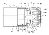
- FIG. 4 is a plan view seen from the lower surface side in a state where a lid member for explaining the structure of the optical connector is removed.
- FIG. 5 is a cross-sectional view taken along line VV in FIG.
- FIG. 6 is a perspective view showing how to attach the ferrule to the housing of the optical connector.
- FIG. 7 is a plan view seen from the lower surface side in a state where a cover member for explaining the movement of the ferrule and the leaf spring of the optical connector is removed.
- FIG. 1 is a perspective view of an optical connector according to an embodiment of the present invention
- FIG. 2 is an exploded perspective view illustrating the structure of the optical connector
- FIG. 3 is a cross-sectional view of a state in which a lid member illustrating the structure of the optical connector is removed.
- 4 is a plan view of the optical connector viewed from the bottom side with the lid member removed
- FIG. 5 is a cross-sectional view taken along the line VV in FIG. 4
- FIG. 6 is a view of the ferrule to the optical connector housing.
- FIG. 7 is a plan view seen from the lower surface side with the cover member for explaining the ferrule of the optical connector and the movement of the leaf spring removed.
- the optical connector 11 includes a housing 12, a pair of ferrules (connection members) 13, a leaf spring (biasing member) 14, and a lid member 15.
- the signal light is transmitted by being fitted to an electronic device or other optical connector mounted on the other side.
- the housing 12 is molded from a synthetic resin such as plastic and has a pair of through holes 21. These through-holes 21 are penetrated from the accommodation chamber 23 formed in the middle part of the housing 12 to the front end, and the ferrule 13 is inserted into these through-holes 21 from the accommodation chamber 23 side.
- the housing 12 has an opening 22 of the accommodation chamber 23 formed on the lower surface thereof, and the leaf spring 14 and the lid member 15 are attached to the accommodation chamber 23 from the opening 22.
- the ferrule 13 inserted into the through hole 21 of the housing 12 is made of a metal such as brass, and has a cylindrical portion 32 having a small diameter portion 31 formed on the tip side, as shown in FIGS. Yes.
- the cylindrical portion 32 is formed with a first flange 33 and a second flange 34 having substantially the same outer diameter at an intermediate portion and a rear end portion in the longitudinal direction.
- the cylindrical portion 32 of the ferrule 13 has a holding cylindrical portion 32a between the first flange 33 and the second flange 34, and has a centering cylindrical portion 32b on the tip side of the first flange 33, and the holding cylindrical portion 32a. Is formed with a smaller diameter than the aligning cylindrical portion 32b.
- the aligning cylindrical portion 32b can be inserted into the through hole 21 of the housing 12 from the housing chamber 23 side, and the first flange 33 is held in a state where the aligning cylindrical portion 32b is inserted into the through hole 21.
- the cylindrical portion 32 a and the second flange 34 are accommodated in the accommodation chamber 23.
- the through hole 21 is formed to have a smaller diameter than the first flange 33, whereby the ferrule 13 inserted into the through hole 21 is engaged with the edge of the through hole 21, and the front side of the ferrule 13 is inserted. Movement to the front side in a certain insertion direction is restricted.
- An optical fiber insertion hole (not shown) is formed at the center of the ferrule 13.
- An optical fiber cable 41 is inserted into the optical fiber insertion hole from the rear end side of the ferrule 13 and connected thereto. ing.
- the optical fiber cable 41 connected to the ferrule 13 is formed by covering the periphery of an optical fiber made of a light guide material with a jacket made of a synthetic resin.
- the optical fibers are formed so as to have different refractive indexes and are mutually connected.
- a multimode plastic optical fiber having a core and a clad arranged coaxially.
- the optical fiber cable 41 is inserted from the rear end side of the ferrule 13, and the end face of the optical fiber is exposed at the front end of the ferrule 13.
- the optical fiber cable 41 is drawn from the end of the optical cable 42.
- the optical cable 42 is obtained by covering a bundled optical fiber cable 41 with a jacket 43, and a boot 44 is provided at an end thereof.
- the boot 44 restricts bending at the end of the optical cable 42 and prevents damage to the optical fiber in the optical fiber cable 41 due to bending.
- a caulking sleeve 45 having a fixed plate portion 45 a is provided at the end of the boot 44, and the optical fiber cable 41 is drawn from the caulking sleeve 45.
- the crimping sleeve 45 is provided with a crimping ring 46, and the jacket 43 and the boot 44 of the optical cable 42 are fixed to the crimping sleeve 45 by the crimping ring 46.
- the caulking sleeve 45 has a fixing plate portion 45 a fitted into the housing chamber 23 from the opening 22 of the housing 12, whereby the boot 44 fixed to the caulking sleeve 45 and the outer sheath 43 of the optical cable 42. The end is fixed to the rear end of the housing 12.
- the leaf spring 14 assembled from the opening 22 of the housing 12 to the accommodation chamber 23 is formed of spring steel.
- the leaf spring 14 has a support portion 51, and a pair of biasing portions 52 are connected to the support portion 51.
- the biasing portion 52 is bent a plurality of times, and the tip thereof is a biasing piece portion 53.
- Concave portions 51 a and 52 a are formed in the support portion 51 and the respective urging portions 52, and the optical fiber cable 41 is passed through the concave portions 51 a and 52 a.
- the leaf spring 14 formed in this way has an opening with the recesses 51a and 52a facing the housing chamber 23 of the housing 12 to which the ferrule 13 is mounted, with the urging piece 53 disposed on the distal end side. 22 is assembled.
- the lid member 15 assembled to the opening 22 of the housing 12 is molded from a synthetic resin such as plastic.
- the lid member 15 has a pressing plate portion 61, and locking walls 62a and 62b extending to one surface side are formed on the pressing plate portion 61 at one side portion.
- the locking wall 62a at the center and the locking walls 62b on both sides are disposed with a space slightly larger than the outer diameter of the optical fiber cable 41, and between the locking walls 62a and 62b.
- the optical fiber cable 41 is passed.
- the locking walls 62b on both sides are formed with locking claws 65 protruding outward at the tip portions.
- a projection 66 is formed on the front side of the central locking wall 62a, and the support 51 of the leaf spring 14 is inserted into a gap 69 formed between the locking wall 62a and the projection 66. Thus, the leaf spring 14 is held by the lid member 15.
- the holding plate portion 61 is formed with a pair of arc-shaped holding recesses 68 on the front side, and these holding recesses 68 are arranged between the first flange 33 and the second flange 34 of the ferrule 13.
- the holding cylindrical portion 32a between the first flange 33 and the second flange 34 is held.
- the lid member 15 formed in this manner is engaged with the housing chamber 23 of the housing 12 in which the ferrule 13 is mounted and the leaf spring 14 is assembled, and the fixing plate portion 45a of the crimping sleeve 45 is fitted.
- the locking walls 62a, 62b and the like are assembled toward the opening 22 in a state where the walls 62a, 62b are arranged on the rear end side. As described above, by attaching the lid member 15 to the opening 22 of the housing 12, the locking walls 62 a and 62 b are disposed on the rear side of the leaf spring 14.
- the leaf spring 14 is held between the rear end portion of the ferrule 13 and the locking walls 62a and 62b, so that the ferrule 13 is urged to the front end side by the urging force of the leaf spring 14.
- the holding recess 68 of the lid member 15 is disposed between the first flange 33 and the second flange 34 of the ferrule 13, and thus the ferrule 13 is held by the holding recess 68 so as to be movable in the axial direction.
- the housing 12 is formed with locking holes 67 in both side walls 71 forming the storage chamber 23, and the locking claws 65 of the locking walls 62b on both sides lock the locking holes 67.
- a lid member 15 is fixed to the housing 12.
- spring deflection preventing projections 72 are formed on the housing 12 on the inner surface side of the both side walls 71 of the housing chamber 23. These spring deflection preventing projections 72 are disposed between the rear end of the ferrule 13 and the locking walls 62 a and 62 b of the lid member 15.
- spring deflection preventing projections 72 are formed from the bottom 23 a of the storage chamber 23 to a position closer to the bottom 23 a than the opening 22 of the storage chamber 23, and are not formed near the edge of the opening 22.
- the spring deflection preventing protrusion 72 is formed on the inner surface of the accommodation chamber 23 excluding the accommodation path of the ferrule 13 to the accommodation chamber 23. Therefore, as shown in FIG. 6, when the ferrule 13 is inserted from the opening 22 of the accommodation chamber 23 and inserted into the through hole 21 and accommodated in the housing 12, the ferrule 13 interferes with the spring deflection preventing projection 72. Problems that interfere with the installation are prevented.
- These spring deflection preventing projections 72 are arranged on the movement path of the ferrule 13, whereby the ferrule 13 is moved rearward against the urging force of the leaf spring 14 as shown in FIG. 7. At this time, the rear end of the ferrule 13 abuts against the spring deflection preventing projection 72. Accordingly, the ferrule 13 is restricted from moving backward relative to the contact position with the spring deflection preventing protrusion 72.
- the optical connector 11 having the above structure is connected to an electronic device or a counterpart optical connector.
- the end face of the ferrule 13 is abutted against the end face of the counterpart ferrule, and transmission of predetermined signal light becomes possible.
- each ferrule 13 is urged toward the distal end side by the leaf spring 14, so that it is pressed against the end face of the counterpart ferrule or the like with an appropriate pressing force, and a good connection state Is maintained.
- the ferrule 13 is moved to the rear end side opposite to the connection direction against the urging force of the leaf spring 14.
- the ferrule 13 abuts against a spring deflection preventing protrusion 72 formed on the housing 12, thereby Movement to the end side is restricted at a predetermined position.
- the ferrule 13 is moved to the rear end side. Even if the leaf spring 14 is deformed by the movement, a good biasing force by the leaf spring 14 is maintained even after that.
- the optical connector 11 when the ferrule 13 moves to the rear end side, first, the urging force of the leaf spring 14 suppresses the movement of the ferrule 13, and further, the spring deflection preventing projection 72 of the housing 12 is regulated. To do. That is, the optical connector 11 is configured to be double-locked by the leaf spring 14 and the spring deflection preventing projection 72 with respect to the movement toward the rear end side of the ferrule 13.
- the optical fiber cable 41 is pulled and the ferrule 13 is moved to the rear end side against the urging force of the leaf spring 14.
- the ferrule 13 comes into contact with the spring deflection preventing projection 72 formed on the rigid housing 12 made of synthetic resin, and the movement of the ferrule 13 toward the rear end side is restricted at a predetermined position.
- plate spring 14 by the movement to the rear end side of the ferrule 13 can be prevented. Accordingly, it is possible to always maintain a good urging force of the leaf spring 14 and maintain connection reliability over a long period of time.
- the elastic force of the plate spring 14 is increased by increasing the plate thickness and obtaining the effect of preventing excessive bending, compared with the case where the plate spring 14 itself is provided with a bending prevention portion, which affects the connection workability. Therefore, good connection workability can be ensured without any trouble, and the position of the ferrule 13 can be regulated with high accuracy by suppressing the accumulation of tolerances.
- optical connector of the present invention it is possible to provide an optical connector with good connection workability and high connection reliability in which a good biasing force in the connection direction is always maintained.
Landscapes
- Physics & Mathematics (AREA)
- General Physics & Mathematics (AREA)
- Optics & Photonics (AREA)
- Mechanical Coupling Of Light Guides (AREA)
Abstract
本発明の課題は、接続作業性が良好であり、しかも、接続方向への良好な付勢力が常に維持された接続信頼性の高い光コネクタを提供することにある。 光ファイバケーブル(41)の端末に取り付けられるフェルール(13)と、フェルール(13)を収容するハウジング(12)と、ハウジング(12)内にてフェルール(13)を先端側へ付勢する板バネ(14)と、ハウジング(12)内におけるフェルール(13)の後端側に形成され、板バネ(14)による付勢力に抗したフェルール(13)の後端側への移動を所定位置にて規制するバネ撓み防止突起(72)とを備える。
Description
本発明は、光ファイバの端末を収容する光コネクタに関する。
近年、自動車のワイヤハーネスとして、回路数の増加及びノイズ対策のため、その一部に光ファイバを被覆した光ファイバケーブルを備えたものが用いられつつある。
このような光ファイバケーブルを備えたワイヤハーネスでは、その光ファイバケーブルの端末を収容する光コネクタが用いられる(例えば、特許文献1参照)。
この種の光コネクタとしては、光ファイバケーブルの端末に取り付けられたフェルールあるいは光接続部品を先端側へ付勢する板バネからなる付勢部材を備えたものが知られている(例えば、特許文献2参照。)。
上記のように、光コネクタでは、板バネによってフェルール等を光軸方向前方側である先端側へ付勢して接続端面同士を押し付け、良好な接続状態を維持するようになっている。
ところで、光ファイバケーブルが引っ張られるなどにより、フェルール等がハウジング内にて接続方向と逆方向である後端側へ移動されることにより、板バネが付勢方向と逆方向へ過度に変形されると、板バネが塑性変形して付勢力が低減してしまうおそれがあった。そして、このような場合、接続端面同士の押し付け力が十分に得られなくなり、要求される接続信頼性が得られなくなることがあった。
上記特許文献2に記載の光コネクタでは、フェルールが引っ張られた際に、フェルールのフランジが接触する第2の直線部からなる過度撓み防止部分を板バネに設けて板バネの過度の撓みを抑えている。しかし、この過度撓み防止部分も板バネの一部からなる薄板であるので、変形し易く、過度撓み防止効果が低かった。なお、過度撓み防止部分における過度撓み防止効果を高めるため、板バネの板厚を厚くすると、板バネの弾性力も大きくなる。この結果、光コネクタの接続時に大きな接続力が必要となって光コネクタの接続作業性に影響を与えてしまう。
本発明は、上述した事情に鑑みてなされたものであり、その目的は、接続作業性が良好であり、しかも、接続方向への良好な付勢力が常に維持された接続信頼性の高い光コネクタを提供することにある。
前述した目的を達成するために、本発明に係る光コネクタは、下記(1)および(2)を特徴としている。
(1) 光ファイバの端末に取り付けられる接続部材と、
前記接続部材を収容するハウジングと、
前記ハウジング内にて前記接続部材を先端側へ付勢する付勢部材と、
前記ハウジング内における前記接続部材の後端側に形成され、前記付勢部材による付勢力に抗した前記接続部材の後端側への移動を所定位置にて規制するバネ撓み防止突起と、
を備えたこと。
(2) 上記(1)の構成の光コネクタにおいて、
前記ハウジングは、前記接続部材を収容する収容室を有し、
前記接続部材は、前記収容室の開口部から前記収容室へ収容され、
前記バネ撓み防止突起は、前記接続部材の前記収容室への収容経路を除く前記収容室の内面に形成されていること。
(1) 光ファイバの端末に取り付けられる接続部材と、
前記接続部材を収容するハウジングと、
前記ハウジング内にて前記接続部材を先端側へ付勢する付勢部材と、
前記ハウジング内における前記接続部材の後端側に形成され、前記付勢部材による付勢力に抗した前記接続部材の後端側への移動を所定位置にて規制するバネ撓み防止突起と、
を備えたこと。
(2) 上記(1)の構成の光コネクタにおいて、
前記ハウジングは、前記接続部材を収容する収容室を有し、
前記接続部材は、前記収容室の開口部から前記収容室へ収容され、
前記バネ撓み防止突起は、前記接続部材の前記収容室への収容経路を除く前記収容室の内面に形成されていること。
上記(1)の構成の光コネクタでは、例えば、光ファイバが引っ張られて接続部材が付勢部材の付勢力に抗して後端側へ移動したとしても、ハウジングに形成されたバネ撓み防止突起によって接続部材の後端側への移動が所定位置にて規制される。したがって、接続部材の後端側への移動による付勢部材の過度の変形による塑性変形を防止することができ、これにより、付勢部材の良好な付勢力を常に維持させ、接続信頼性を長期にわたって維持させることができる。
また、付勢部材自体に撓み防止部分を設ける場合と比較して、過度撓み防止効果を得るために弾性力が増大して接続作業性に影響を与えてしまうような不具合なく、良好な接続作業性を確保することができ、また、公差の累積を抑制して精度良く接続部材の位置を規制することができる。
上記(2)の構成の光コネクタでは、バネ撓み防止突起が、収容室への接続部材の収容経路を除く収容室の内面に形成されているので、接続部材を、収容室の開口部から入れて収容する際に、接続部材がバネ撓み防止突起に干渉して装着の邪魔となるような不具合を防止することができる。
また、付勢部材自体に撓み防止部分を設ける場合と比較して、過度撓み防止効果を得るために弾性力が増大して接続作業性に影響を与えてしまうような不具合なく、良好な接続作業性を確保することができ、また、公差の累積を抑制して精度良く接続部材の位置を規制することができる。
上記(2)の構成の光コネクタでは、バネ撓み防止突起が、収容室への接続部材の収容経路を除く収容室の内面に形成されているので、接続部材を、収容室の開口部から入れて収容する際に、接続部材がバネ撓み防止突起に干渉して装着の邪魔となるような不具合を防止することができる。
本発明によれば、接続作業性が良好であり、しかも、接続方向への良好な付勢力が常に維持された接続信頼性の高い光コネクタを提供できる。
以上、本発明について簡潔に説明した。更に、以下に説明される発明を実施するための形態を添付の図面を参照して通読することにより、本発明の詳細は更に明確化されるであろう。
以下、本発明に係る実施形態の光コネクタを、図面を参照して説明する。
図1は本発明の実施形態に係る光コネクタの斜視図、図2は光コネクタの構造を説明する分解斜視図、図3は光コネクタの構造を説明する蓋部材を取り外した状態の断面図、図4は光コネクタの構造を説明する蓋部材を取り外した状態で下面側から視た平面図、図5は図4におけるV-V線の断面図、図6は光コネクタのハウジングへのフェルールの装着の仕方を示す斜視図、図7は光コネクタのフェルール及び板バネの動きを説明する蓋部材を取り外した状態で下面側から視た平面図である。
図1から図4に示すように、光コネクタ11は、ハウジング12と、一対のフェルール(接続部材)13と、板バネ(付勢部材)14と、蓋部材15とを備えたもので、自動車などに装備される電子機器や相手側の光コネクタなどと嵌合して信号光を伝送するものである。
ハウジング12は、プラスチックなどの合成樹脂から成型されたもので、一対の貫通孔21を有している。これら貫通孔21は、ハウジング12の中間部に形成された収容室23から先端にわたって貫通されており、これら貫通孔21に、収容室23側からフェルール13が挿入される。
このハウジング12には、その下面に、収容室23の開口部22が形成されており、この開口部22から収容室23へ板バネ14及び蓋部材15が取り付けられる。
ハウジング12の貫通孔21へ挿入されるフェルール13は、真鍮などの金属からなるもので、図2及び図3に示すように、先端側に小径部31が形成された円筒部32を有している。円筒部32には、長手方向の中間部及び後端部に、略同一外径を有する第1フランジ33及び第2フランジ34が形成されている。
フェルール13の円筒部32は、第1フランジ33と第2フランジ34との間が保持円筒部32aとされ、第1フランジ33よりも先端側が調心円筒部32bとされており、保持円筒部32aは、調心円筒部32bよりも小径に形成されている。そして、この調心円筒部32bが、ハウジング12の貫通孔21へ、収容室23側から挿入可能とされ、この調心円筒部32bを貫通孔21へ挿入した状態で、第1フランジ33、保持円筒部32a及び第2フランジ34が収容室23に収容される。貫通孔21は、第1フランジ33よりも小径に形成されており、これにより、貫通孔21へ挿入したフェルール13は、第1フランジ33が貫通孔21の縁部に係合し、先端側である挿入方向前方側への移動が規制される。
このフェルール13には、その中心に、光ファイバ挿通孔(図示略)が形成されており、この光ファイバ挿通孔には、フェルール13の後端側から光ファイバケーブル41が挿し込まれて接続されている。
このフェルール13に接続される光ファイバケーブル41は、導光材料からなる光ファイバの周囲を合成樹脂からなる外被によって覆ったもので、光ファイバは、互いに屈折率が異なるように形成されかつ互いに同軸的に配されたコアとクラッドとを備えた、例えば、マルチモードプラスチック光ファイバである。
そして、この光ファイバケーブル41は、フェルール13の後端側から挿し込まれ、光ファイバの端面がフェルール13の先端において露出されている。
また、光ファイバケーブル41は、光ケーブル42の端部から引き出されている。光ケーブル42は、束ねた光ファイバケーブル41を外被43で覆ったもので、その端部には、ブーツ44が設けられている。そして、このブーツ44によって光ケーブル42の端部における曲げが規制され、曲げによる光ファイバケーブル41内の光ファイバへの損傷が防止されている。また、このブーツ44の端部には、固定板部45aを有する加締めスリーブ45が設けられ、この加締めスリーブ45から光ファイバケーブル41が引き出されている。この加締めスリーブ45には、加締めリング46が設けられ、この加締めリング46によって光ケーブル42の外被43及びブーツ44が加締めスリーブ45に固定されている。
この加締めスリーブ45は、その固定板部45aが、ハウジング12の開口部22から収容室23へ嵌合され、これにより、加締めスリーブ45に固定されたブーツ44及び光ケーブル42の外被43の端部がハウジング12の後端部に固定される。
ハウジング12の開口部22から収容室23へ組み付けられる板バネ14は、バネ鋼から形成されたものである。板バネ14は、支持部51を有しており、この支持部51に一対の付勢部52が連結されている。付勢部52は、複数回屈曲され、その先端が付勢片部53とされている。支持部51及びそれぞれの付勢部52には、凹部51a,52aが形成されており、これらの凹部51a,52aには、光ファイバケーブル41が通される。
このように形成された板バネ14は、フェルール13が装着されたハウジング12の収容室23に対して、付勢片部53を先端側へ配置させた状態で凹部51a,52aを向けて開口部22から組み付けられる。
ハウジング12の開口部22に組み付けられる蓋部材15は、プラスチックなどの合成樹脂から成型されたものである。この蓋部材15は、押さえ板部61を有しており、この押さえ板部61には、一側部にて、一方の面側へ延在する係止壁62a,62bが形成されている。中央の係止壁62aと両側部の係止壁62bとは、光ファイバケーブル41の外径よりも僅かに大きな間隔をあけて配置されており、これらの係止壁62a,62b同士の間に、光ファイバケーブル41が通される。両側の係止壁62bは、その先端部分に、外側へ突出する係止爪65が形成されている。
また、中央の係止壁62aの前方側には、突起部66が形成されており、係止壁62aと突起部66との間に形成された隙間69に、板バネ14の支持部51が挿し込まれ、よって、板バネ14が蓋部材15によって保持される。
また、押さえ板部61には、前方側に円弧状の一対の保持凹部68が形成されており、これらの保持凹部68は、フェルール13の第1フランジ33と第2フランジ34との間に配置され、これら第1フランジ33と第2フランジ34との間の保持円筒部32aを保持する。
このように形成された蓋部材15は、フェルール13が装着されて板バネ14が組み付けられ、加締めスリーブ45の固定板部45aが嵌合されたハウジング12の収容室23に対して、係止壁62a,62bを後端側へ配置させた状態にて係止壁62a,62b等を開口部22に向けて組み付けられる。このように、ハウジング12の開口部22へ蓋部材15を組み付けることにより、板バネ14の後方側に、係止壁62a,62bが配置される。これにより、板バネ14は、フェルール13の後端部と係止壁62a,62bとの間に保持され、よって、フェルール13は、板バネ14の付勢力によって先端側へ付勢された状態となる。さらに、蓋部材15の保持凹部68が、フェルール13の第1フランジ33と第2フランジ34との間に配置され、よって、フェルール13は、保持凹部68によって軸方向へ移動可能に保持される。
また、ハウジング12には、収容室23を形成する両側壁71に係止孔67が形成されており、両側の係止壁62bの係止爪65が係止孔67を係止し、よって、ハウジング12に蓋部材15が固定される。
また、図5に示すように、ハウジング12には、収容室23の両側壁71の内面側に、バネ撓み防止突起72が形成されている。これらのバネ撓み防止突起72は、フェルール13の後端と蓋部材15の係止壁62a,62bとの間に配置されている。
これらのバネ撓み防止突起72は、収容室23の底部23aから収容室23の開口部22よりも底部23a寄りの位置まで形成されており、開口部22の縁部付近には形成されていない。これにより、このバネ撓み防止突起72は、収容室23へのフェルール13の収容経路を除く収容室23の内面に形成された状態となっている。したがって、図6に示すように、フェルール13を、収容室23の開口部22から入れて貫通孔21へ挿し込んでハウジング12へ収容する際に、フェルール13がバネ撓み防止突起72に干渉して装着の邪魔となるような不具合が防止される。
これらのバネ撓み防止突起72は、フェルール13の移動経路上に配置されており、これにより、図7に示すように、フェルール13が板バネ14の付勢力に抗して後方側へ移動された際に、フェルール13の後端がバネ撓み防止突起72へ当接する。したがって、フェルール13は、バネ撓み防止突起72との当接位置よりも後方側への移動が規制される。
上記構造の光コネクタ11は、電子機器や相手側の光コネクタなどに接続される。これにより、フェルール13の端面が相手側のフェルールの端面等に突き合わされ、所定の信号光の伝送が可能となる。
このとき、光コネクタ11では、板バネ14によってそれぞれのフェルール13が先端側へ付勢されているので、相手側のフェルール等の端面に対して適度な押圧力にて押し付けられ、良好な接続状態が維持される。
ここで、何らかの原因により光ファイバケーブル41が引っ張られると、フェルール13は、板バネ14の付勢力に抗して接続方向と逆方向である後端側へ移動される。このフェルール13の後端側への移動が大きいと、図7に示すように、フェルール13は、その後端がハウジング12に形成されたバネ撓み防止突起72に当接し、これにより、フェルール13の後端側への移動が所定位置にて規制される。
したがって、このフェルール13の後端側への移動を規制する所定位置を、板バネ14が過度に変形して付勢力が低下することがない位置としておくことにより、フェルール13の後端側への移動によって板バネ14が変形したとしても、その後においても板バネ14による良好な付勢力が維持される。
このように、光コネクタ11では、フェルール13が後端側へ移動した際に、まず、板バネ14の付勢力がフェルール13の移動を抑制し、さらに、ハウジング12のバネ撓み防止突起72が規制する。つまり、この光コネクタ11は、フェルール13の後端側への移動に対して板バネ14及びバネ撓み防止突起72によって二重係止を行うようになっている。
以上、説明したように、本実施形態にかかる光コネクタ11によれば、例えば、光ファイバケーブル41が引っ張られてフェルール13が板バネ14の付勢力に抗して後端側へ移動されたとしても、合成樹脂から形成された剛性を有するハウジング12に形成されたバネ撓み防止突起72にフェルール13が当接し、フェルール13の後端側への移動が所定位置にて規制される。これにより、フェルール13の後端側への移動による板バネ14の過度の変形による塑性変形を防止することができる。したがって、板バネ14の良好な付勢力を常に維持させ、接続信頼性を長期にわたって維持させることができる。
また、板バネ14自体に撓み防止部分を設ける場合と比較して、板厚を厚くして過度撓み防止効果を得ることによって板バネ14の弾性力が増大し、接続作業性に影響を与えてしまうような不具合なく、良好な接続作業性を確保することができ、また、公差の累積を抑制して精度良くフェルール13の位置を規制することができる。
なお、本発明は、上述した実施形態に限定されるものではなく、適宜、変形、改良等が可能である。その他、上述した実施形態における各構成要素の材質、形状、寸法、数値、形態、数、配置箇所等は本発明を達成できるものであれば任意であり、限定されない。
本発明を詳細にまた特定の実施態様を参照して説明したが、本発明の精神と範囲を逸脱することなく様々な変更や修正を加えることができることは当業者にとって明らかである。
本出願は、2010年10月28日出願の日本特許出願(特願2010-242407)に基づくものであり、その内容はここに参照として取り込まれる。
本発明の光コネクタによれば、接続作業性が良好であり、しかも、接続方向への良好な付勢力が常に維持された接続信頼性の高い光コネクタを提供できる、という効果を奏する。
11 光コネクタ
12 ハウジング
13 フェルール(接続部材)
14 板バネ(付勢部材)
15 蓋部材
21 貫通孔
22 開口部
23 収容室
33 第1フランジ
34 第2フランジ
41 光ファイバケーブル
42 光ケーブル
43 外被
44 ブーツ
45 加締めスリーブ
46 加締めリング
51 支持部
52 付勢部
53 付勢片部
61 押さえ板部
62a,62b 係止壁
65 係止爪
66 突起部
67 係止孔
68 保持凹部
71 両側壁
72 バネ撓み防止突起
12 ハウジング
13 フェルール(接続部材)
14 板バネ(付勢部材)
15 蓋部材
21 貫通孔
22 開口部
23 収容室
33 第1フランジ
34 第2フランジ
41 光ファイバケーブル
42 光ケーブル
43 外被
44 ブーツ
45 加締めスリーブ
46 加締めリング
51 支持部
52 付勢部
53 付勢片部
61 押さえ板部
62a,62b 係止壁
65 係止爪
66 突起部
67 係止孔
68 保持凹部
71 両側壁
72 バネ撓み防止突起
Claims (2)
- 光ファイバの端末に取り付けられる接続部材と、
前記接続部材を収容するハウジングと、
前記ハウジング内にて前記接続部材を先端側へ付勢する付勢部材と、
前記ハウジング内における前記接続部材の後端側に形成され、前記付勢部材による付勢力に抗した前記接続部材の後端側への移動を所定位置にて規制するバネ撓み防止突起と、
を備えた光コネクタ。 - 前記ハウジングは、前記接続部材を収容する収容室を有し、
前記接続部材は、前記収容室の開口部から前記収容室へ収容され、
前記バネ撓み防止突起は、前記接続部材の前記収容室への収容経路を除く前記収容室の内面に形成されている請求項1に記載の光コネクタ。
Applications Claiming Priority (2)
| Application Number | Priority Date | Filing Date | Title |
|---|---|---|---|
| JP2010242407A JP5970156B2 (ja) | 2010-10-28 | 2010-10-28 | 光コネクタ |
| JP2010-242407 | 2010-10-28 |
Publications (1)
| Publication Number | Publication Date |
|---|---|
| WO2012056908A1 true WO2012056908A1 (ja) | 2012-05-03 |
Family
ID=45993632
Family Applications (1)
| Application Number | Title | Priority Date | Filing Date |
|---|---|---|---|
| PCT/JP2011/073733 Ceased WO2012056908A1 (ja) | 2010-10-28 | 2011-10-14 | 光コネクタ |
Country Status (2)
| Country | Link |
|---|---|
| JP (1) | JP5970156B2 (ja) |
| WO (1) | WO2012056908A1 (ja) |
Cited By (2)
| Publication number | Priority date | Publication date | Assignee | Title |
|---|---|---|---|---|
| WO2014196538A1 (ja) * | 2013-06-04 | 2014-12-11 | 矢崎総業株式会社 | 光コネクタ |
| CN114114557A (zh) * | 2021-12-03 | 2022-03-01 | 杭州润州光电技术有限公司 | 一种跳线快速连接器及光纤跳线 |
Families Citing this family (2)
| Publication number | Priority date | Publication date | Assignee | Title |
|---|---|---|---|---|
| JP5812335B2 (ja) * | 2011-10-12 | 2015-11-11 | 株式会社オートネットワーク技術研究所 | 光コネクタ |
| JP6272649B2 (ja) * | 2013-02-15 | 2018-01-31 | 矢崎総業株式会社 | 光コネクタ |
Citations (4)
| Publication number | Priority date | Publication date | Assignee | Title |
|---|---|---|---|---|
| JPH05188240A (ja) * | 1992-01-10 | 1993-07-30 | Nec Corp | 光コネクタ端末構造 |
| JP2002202434A (ja) * | 2000-12-28 | 2002-07-19 | Furukawa Electric Co Ltd:The | 光コネクタ接続構造 |
| JP2008513844A (ja) * | 2004-09-24 | 2008-05-01 | ライヒル ウント デ−マッサリ アーゲー | 光ファイバコネクタ用内側ハウジング |
| JP2008276063A (ja) * | 2007-05-02 | 2008-11-13 | Sumitomo Electric Ind Ltd | 光コネクタ及び光コネクタの組立方法 |
Family Cites Families (5)
| Publication number | Priority date | Publication date | Assignee | Title |
|---|---|---|---|---|
| JP3259947B2 (ja) * | 1996-09-24 | 2002-02-25 | 住友電装株式会社 | 光コネクタのブーツ取付構造 |
| JP2002169065A (ja) * | 2000-11-30 | 2002-06-14 | Fujikura Ltd | 光トランシーバ |
| JP4064784B2 (ja) * | 2002-10-16 | 2008-03-19 | 矢崎総業株式会社 | 光コネクタ |
| JP4091011B2 (ja) * | 2004-03-16 | 2008-05-28 | 株式会社フジクラ | 光コネクタ |
| JP4482591B2 (ja) * | 2008-03-28 | 2010-06-16 | ホシデン株式会社 | 光コネクタ |
-
2010
- 2010-10-28 JP JP2010242407A patent/JP5970156B2/ja not_active Expired - Fee Related
-
2011
- 2011-10-14 WO PCT/JP2011/073733 patent/WO2012056908A1/ja not_active Ceased
Patent Citations (4)
| Publication number | Priority date | Publication date | Assignee | Title |
|---|---|---|---|---|
| JPH05188240A (ja) * | 1992-01-10 | 1993-07-30 | Nec Corp | 光コネクタ端末構造 |
| JP2002202434A (ja) * | 2000-12-28 | 2002-07-19 | Furukawa Electric Co Ltd:The | 光コネクタ接続構造 |
| JP2008513844A (ja) * | 2004-09-24 | 2008-05-01 | ライヒル ウント デ−マッサリ アーゲー | 光ファイバコネクタ用内側ハウジング |
| JP2008276063A (ja) * | 2007-05-02 | 2008-11-13 | Sumitomo Electric Ind Ltd | 光コネクタ及び光コネクタの組立方法 |
Cited By (3)
| Publication number | Priority date | Publication date | Assignee | Title |
|---|---|---|---|---|
| WO2014196538A1 (ja) * | 2013-06-04 | 2014-12-11 | 矢崎総業株式会社 | 光コネクタ |
| JP2014235371A (ja) * | 2013-06-04 | 2014-12-15 | 矢崎総業株式会社 | 光コネクタ |
| CN114114557A (zh) * | 2021-12-03 | 2022-03-01 | 杭州润州光电技术有限公司 | 一种跳线快速连接器及光纤跳线 |
Also Published As
| Publication number | Publication date |
|---|---|
| JP2012093634A (ja) | 2012-05-17 |
| JP5970156B2 (ja) | 2016-08-17 |
Similar Documents
| Publication | Publication Date | Title |
|---|---|---|
| JP5599237B2 (ja) | 光コネクタ | |
| JP6272649B2 (ja) | 光コネクタ | |
| JP2010256703A (ja) | 光コネクタ | |
| CN111433647B (zh) | 光连接器 | |
| JP2004138707A (ja) | 光コネクタ | |
| JP5970156B2 (ja) | 光コネクタ | |
| JP4800136B2 (ja) | 光レセプタクルハウジング、光コネクタレセプタクル及び光機器 | |
| JP5344095B2 (ja) | 光コネクタ用スリーブおよび光コネクタ | |
| JP6018841B2 (ja) | フェルール及び光コネクタ | |
| US20100272396A1 (en) | Lc-type optical connector | |
| JP6251512B2 (ja) | 光コネクタ | |
| JP6564566B2 (ja) | 光コネクタ構造 | |
| WO2014119585A1 (ja) | 光コネクタ及び光コネクタの組立方法 | |
| JP5269746B2 (ja) | 光コネクタ | |
| JP2014186274A (ja) | コネクタ | |
| JP4786394B2 (ja) | フェルール固定構造 | |
| JP7661137B2 (ja) | 光コネクタ | |
| JP7552928B2 (ja) | 光-電気複合コネクタ | |
| JP2015500516A (ja) | 光コネクタ | |
| WO2019058769A1 (ja) | 光コネクタ装置 | |
| JP5508103B2 (ja) | 光ケーブルコネクタ | |
| JP6267875B2 (ja) | 光コネクタ | |
| JP6259223B2 (ja) | 光ファイバの端末構造 | |
| JP2010054681A (ja) | 光ケーブルコネクタ | |
| JP2014202836A (ja) | 光コネクタ |
Legal Events
| Date | Code | Title | Description |
|---|---|---|---|
| 121 | Ep: the epo has been informed by wipo that ep was designated in this application |
Ref document number: 11836047 Country of ref document: EP Kind code of ref document: A1 |
|
| NENP | Non-entry into the national phase |
Ref country code: DE |
|
| 122 | Ep: pct application non-entry in european phase |
Ref document number: 11836047 Country of ref document: EP Kind code of ref document: A1 |