WO2012053293A1 - ケーブル施工支援・管理システム - Google Patents
ケーブル施工支援・管理システム Download PDFInfo
- Publication number
- WO2012053293A1 WO2012053293A1 PCT/JP2011/070617 JP2011070617W WO2012053293A1 WO 2012053293 A1 WO2012053293 A1 WO 2012053293A1 JP 2011070617 W JP2011070617 W JP 2011070617W WO 2012053293 A1 WO2012053293 A1 WO 2012053293A1
- Authority
- WO
- WIPO (PCT)
- Prior art keywords
- cable
- information
- work
- worker
- management system
- Prior art date
Links
Images


Classifications
-
- G—PHYSICS
- G06—COMPUTING; CALCULATING OR COUNTING
- G06Q—INFORMATION AND COMMUNICATION TECHNOLOGY [ICT] SPECIALLY ADAPTED FOR ADMINISTRATIVE, COMMERCIAL, FINANCIAL, MANAGERIAL OR SUPERVISORY PURPOSES; SYSTEMS OR METHODS SPECIALLY ADAPTED FOR ADMINISTRATIVE, COMMERCIAL, FINANCIAL, MANAGERIAL OR SUPERVISORY PURPOSES, NOT OTHERWISE PROVIDED FOR
- G06Q10/00—Administration; Management
- G06Q10/06—Resources, workflows, human or project management; Enterprise or organisation planning; Enterprise or organisation modelling
Definitions
- the present invention relates to a cable construction support / management system, and more particularly to a technology for supporting / managing electrical cable laying work in a large plant facility or the like.
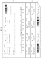
- FIG. 17 is a diagram showing the flow of conventional cable design construction and management.
- necessary information is collected for each cable based on the upstream design information (step A).
- the cable length is determined by selection of the laying route (the point number of the cable tray (cable rack) for laying the cable) (step B), and the size and line type of the cable are selected (step C). Then, the processes of steps A, B, and C are performed for each cable number (step D).
- Step E in addition to the size, line type, length, and number of cores of the cable, information on the arrival / departure point name / laying route (point number of cable tray, passing conduit number, etc.) is available.
- the information table is called a wiring table. Cables are arranged based on the wiring table (Step F).
- the cable laying card has a portion on which all information is printed (half-stake X), a portion that is cut off by a perforation, and is attached to both ends of the cable to be laid (strip stub Y)
- the stub Y is used for laying and a terminal / connection mark.
- the desired cable is cut from the cable drum based on the information recorded on the cable laying card (step K), and the half of the cut cable is cut from the stub X.
- a ticket Y is pasted (step L).
- the cable with the stub Y attached is laid along the laying path printed on the stub X (step M).
- a laying check table is printed on the back of the stub X, and a confirmation check is performed after the laying operation.
- the cable terminal is processed (peeling, terminal attachment) (step N), and then the cable is connected to the board and the terminal block (step O).
- the cable connection position information to the equipment or electrical panel required for the work in the above steps N and O is obtained from the connection drawing created based on the sequence drawing. Do it while watching. After confirming that the connection position is as shown in the drawing after connection, the operator places a check mark on the recording sheet (step P).
- the administrator verifies the wiring connected to the connection drawing, confirms that the work is correct, and then signs the administrator's confirmation on the recording sheet.
- connection drawings and recording paper are used, the soundness of the work cannot be confirmed by itself, and the connection drawing and recording paper are both paper, and work traceability is achieved.
- the paper scanning method cannot be searched from the information described).
- the work to remove or restore the wiring in the test etc. is managed by using the paper different from the recording paper of the worker who made the initial connection, so it is necessary to grasp the latest connection status
- time delay In addition to the fact that time delay always occurs, there is a disadvantage that the value of consistency as a work record is lost because the recording paper is different.
- when performing work progress and budget management based on the work progress status of laying / terminal / connection when checking the remaining cable material and checking inventory after separation, information is scattered throughout the process. Therefore, there is a drawback that an error due to time delay is always easy to occur.
- Patent Document 1 reads or inputs a bar code (data necessary for cable laying work management) displayed on the cable so that the required data is input to the information processing apparatus without human error.
- a bar code data necessary for cable laying work management
- Patent Document 2 uses a RFID instead of a bar code to assist the cable laying work from the design department to each worker in the field, and to save work and confirmation work by digitizing the work completion confirmation record. Attempts have been made to improve the reliability (to ensure traceability) of information exchange such as worker authentication, work permission, work result report, and check report as well as speeding up. However, there is no function to prevent unauthorized work performed by an unauthorized worker (or an unauthorized person) impersonating an authorized worker, leaving room for security improvement on the system. It was.
- the present invention has been made in view of such circumstances, and by displaying work information based on a match between the worker ID of the worker and the work permitter ID downloaded from the server,
- the purpose is to provide a high-security cable construction and management system that saves labor and speed, and prevents unauthorized work by unauthorized persons.
- the invention according to claim 1 is composed of a portable terminal carried by an operator and a server that exchanges necessary information via the network with the portable terminal.
- the portable terminal is Worker reading means for reading the worker information from a worker authentication card affixed to the helmet of the worker performing the work and recorded worker information including the worker ID; First storage means for storing the read worker information; cable reading means for reading cable identification information from the cable laying card; Secondly, work information including support information provided from the server for supporting the work of the work-permitted cable and worker information including a permitter ID related to the work-permitted person is downloaded and stored in association with the cable identification information in advance.
- Storage means Work information acquisition means for acquiring work information for the corresponding cable from the second storage means based on the cable identification information read by the cable reading means;
- a collating unit that outputs display permission information when the worker ID of the worker information stored in the first storage unit matches the permitter ID of the worker information stored in the second storage unit.
- Display means for displaying the work information acquired by the work information acquisition means by the display permission information
- the server Third information storage means for storing support information for supporting the work of each cable installed in the facility and worker information having a permitter ID related to the work permitter in association with each cable identification information
- Extraction means for extracting work information of the corresponding cable from the third storage means from the third storage means in response to a download request from the portable terminal
- Work information providing means for providing work information extracted by the extracting means together with cable identification information to the portable terminal is provided.
- each worker downloads the work information that supports the work for the work permission cable provided from the server and is associated with the cable identification information in advance to the portable terminal that the worker carries.
- the cable identification information of the cable is read from the cable laying card attached to the end of the cable using the reading means of the portable terminal, and the corresponding work information is downloaded from the downloaded work information based on the cable identification information.
- Obtains work information for the cable reads out the worker ID related to the worker himself from the worker authentication card affixed to the worker's own helmet, compares it with the work permitter ID included in the work information, and matches Only when it is done, it is displayed on the display means of the portable terminal. Thereby, each worker can perform a necessary work while viewing the work information displayed on the display means.
- the invention according to claim 2 is composed of a portable terminal carried by an operator and a server for transferring necessary information between the portable terminal via a network, and a cable in which unique cable identification information is recorded.
- the portable terminal is Worker reading means for reading the worker information from the worker authentication card affixed to the helmet of the worker performing the work and storing worker information including the worker ID; First storage means for storing read worker information; cable reading means for reading cable identification information from the cable card; Based on the cable identification information read by the cable reading means, work information acquisition means for acquiring worker information having support information related to the work of the corresponding cable and work permit person ID from the server; A collation unit that outputs display permission information when the worker ID stored in the first storage unit and the permitter ID acquired by the work information acquisition unit match and match; Display means for displaying the work information acquired by the work information acquisition means by the display permission information from the verification means;
- the server A third storage means for storing support information for
- the work information for supporting the work for the work permission cable is first downloaded from the server.
- the invention according to claim 2 uses the cable reading means of the portable terminal to connect the cable.
- the cable identification information is read from the attached cable laying card, it is different from the invention according to claim 1 in that the corresponding cable work information is acquired from the server based on the read cable identification information.
- the cable laying card is attached to both ends of the cable, and the cable laying card attached to both ends of the cable is It is characterized in that different cable identification information is recorded. In many cases, both ends of the cable are connected to different types of boards and terminal blocks, and work information relating to connection for each end of the cable can be acquired.
- the cable construction support / management system according to claim 1, wherein the cable laying card is a card in which an RFID tag is inserted or a card on which a barcode is printed.
- the cable reading means of the portable terminal is an RFID tag reader or a barcode reader.
- the cable construction support / management system according to any one of claims 1 to 4, wherein the portable terminal is at least a worker as authentication information of a worker for receiving permission to access the server. Information is input by the operator reading means. As a result, unauthorized access can be prevented, and only work information required by the worker can be sent according to the access right of the worker who has accessed.
- the worker authentication information is recorded in an RFID tag inserted in an authentication card for each worker, and
- the RFID is integrated with a name display card attached to a helmet owned by the worker, and the worker reading means is an RFID tag reader. Note that when the RFID and the name display card are integrated, when the both are intentionally separated, the separation action physically appears on the name display card. For example, when the name display card and the RFID are covered with a film and separated, the film is damaged, and it can be confirmed that there is a security problem in appearance.
- the mobile terminal includes a registration unit that registers the end of work corresponding to the support information, and the registration unit
- the cable identification information, registration date and time, and worker authentication information are uploaded to the server at the end of the work or when an upload instruction is input.
- a work history such as which work is completed by which worker and when.
- the support information includes a cable cutting operation for cutting a cable having a length designed from a cable drum, Cable laying work for laying the cut cables along the designed route, terminal processing work for processing the cable terminals at both ends of the laid cable to be connectable, terminal processed cable terminals on the panel and terminal block It includes one or more operations among information relating to a cable connection operation to be connected and a check operation of the connected cable.
- the support information related to the cable cutting work includes information for identifying a cable and a design length of the cable. It is said.
- the support information related to the cable laying work includes route information for laying the cable.
- the route information for laying the cable is indicated by a point number of a cable tray (cable rack), for example.
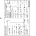
- the cable construction support / management system according to any one of claims 8 to 10, wherein the support information regarding the terminal processing work, the cable connection work, and the check work includes a cable connection diagram. It is said.
- the support information on the check work includes a check list.
- FIG. 1 is a schematic configuration diagram of a cable construction support / management system according to the present invention. Schematic which shows the state affixed on the name display card and the helmet.
- the flowchart of collation processing of worker ID and permitter ID. 1 is an overall configuration diagram of a cable construction support / management system according to the present invention.
- work in the cable construction assistance / management system which concerns on this invention.
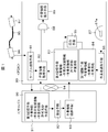
- FIG. 1 is a schematic configuration diagram of a cable construction support / management system.
- the cable construction support / management system includes a portable terminal (PDA) 80 carried by an operator and a server 90 that exchanges necessary information with the portable terminal 80 via a network 94.
- the cable laying cards 96 and 97 in which unique cable identification information is recorded are constituted by cables 95 attached.
- the portable terminal 80 is recorded with worker information (including name display card information as well as permission / non-qualification of cable connection work) attached to the helmet 87 of the worker who performs the work and including the worker ID.
- the worker reading means 86 for reading the worker information from the RFID of the worker authentication card 87a, the first storage means 84 for storing the read worker information, and the RFID of the cable laying cards 96 and 97 for the cable
- the cable reading unit 81 that reads the identification information, the support information that supports the work of the work permission cable provided from the server 90, and the work information that includes the worker information including the permitter ID related to the work permitter, Second storage means 83 for downloading and storing in association with information, and cable read by the cable reading means 81 Based on the identification information, the work information acquisition means 82 for acquiring the work information for the corresponding cable from the second storage means 83, the worker ID of the worker information stored in the first storage means 84, and the first 2 When the permitter IDs of the worker information stored in the storage unit 83
- the server 90 stores support information for supporting the work of each cable installed in the facility and worker information having a permitter ID related to the work permitter in association with each cable identification information.
- an extraction unit 92 for extracting work information of the corresponding cable from the third storage unit 91 from the third storage unit in response to a download request from the portable terminal 80, and an operation extracted by the extraction unit 92
- Work information providing means 93 for providing information to the portable terminal 80 together with cable identification information is provided.
- work information for supporting work on the work permission cable is first downloaded (preliminarily) from the server 90 to the second storage means 83.
- the cable identification information read from the server 90 is used.
- the configuration may be such that the work information of the corresponding cable is downloaded to the work information acquisition means 81 based on the above.
- the second storage unit 83 is not built in the portable terminal 80, and the work information is downloaded from the server 90 to the work information acquisition unit 81 as indicated by the broken line, and the work information from the work information acquisition unit 81 is Is input by the collation means 85 as indicated by a broken line, and is compared with the worker information from the first storage means 84.
- FIG. 2 is a diagram showing the worker authentication card 87a affixed to the helmet 87 of the operator who performs the cable laying operation and the appearance of the affixed helmet 87.
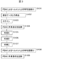
- FIG. 3 is a flowchart showing a schematic flow of work accompanying reading of worker information on the worker authentication card on the helmet.
- step (S) 101 of FIG. 3 the worker information including the worker ID in the RFID 87b of the worker authentication card 87a on the helmet in the PDA 80 is read, and downloaded in advance from the server in S102 to the first storage means. It collates with the worker information including the stored permitter ID. Based on the matching result of the collation, login is performed in S103, and the worker ID is recorded in the PDA in S104. Next, operations A to C necessary for cable laying are performed in steps S105 to S107 while viewing the operation support information in the displayed operation information.
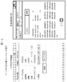
- the work support information of the displayed work information includes a screen for cable separation work, a screen for cable information (cable number, design length, line type, number of cores, specification code), and the like.
- the RFID worker information of the worker authentication card 87a on the helmet is read again in S108, and the worker ID of the worker information is again recorded in the PDA in S109.
- the RFID worker information of the worker authentication card 87a on the helmet is read again in S108, and the worker ID of the worker information is again recorded in the PDA in S109.
- the worker displays the company name, name, work qualification, blood type, and other information displayed on the helmet distributed to each worker at the work site.
- RFID reader with information printing information on name display card, whether or not cable connection work is permitted, whether or not qualified
- worker information is provided on the PDA at the start and end of work
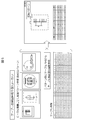
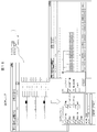
- FIG. 4 is an overall configuration diagram of a cable construction support / management system according to the present invention.
- This cable construction support / management system includes a design database server (DB server) 10, a construction DB server 20, a construction management DB server 30, and a nuclear power plant that are mainly installed in a company that performs cable construction.
- the servers 10, 20, and 30 correspond to the server 90 in FIG. 1
- the PDA 50 corresponds to the PDA 80 in FIG.
- the in-house design DB server 10, the construction DB server 20, the construction management DB server 30, and the local office personal computer 40 are connected to each other by dedicated lines.
- the PDA 50 and the tablet PC 60 have a built-in wireless LAN communication function, and each DB server connected to a dedicated line through a wireless access point 70 installed for each floor of a building or for each predetermined area. Can communicate with.
- the design DB server 50 manages information related to cables (cable information, device information, specifications, cable routes), information related to cable connection diagrams (terminal block information, cable information, device information, pattern diagrams), and the like. Information for construction permitted by the design department is passed to the construction DB server 20.
- a personal computer (not shown) installed in the design department stores a cable connection diagram automatic generation program.
- This personal computer stores a pattern diagram and cable information for each local device as shown in FIG. Based on the ECWD method (ElementaryECcontrol wiring diagrams), etc., a cable connection diagram is automatically generated.
- the personal computer has a function of editing the cable connection diagram automatically generated as described above.
- the design DB server 10 also manages information on this cable connection diagram.
- the construction management DB server 30 manages the personal information of the employee based on the authentication information (user ID) of the employee (worker) and manages the actual data of cable construction.
- the employee is an employee including the worker
- the authentication information in the case of the worker is worker information including “permitter ID” and “work qualification”.
- the local office PC 40 outputs the cable number printing information to the printer 42 and prints the cable number on the cable laying card.
- an RFID tag RFID: Radio Frequency Identification
- RFID tag has unique cable identification information (cable ID) corresponding to the cable number on a one-to-one basis. It is recorded.
- the personal computer 40 outputs the worker information print information to the printer 42, and causes the worker information to be printed on the worker authentication card 87a.
- An RFID tag 87b is inserted in the worker authentication card 87a in advance, and unique information corresponding to the printed worker information is recorded on the RFID tag.
- the worker information includes a company name, name, work qualification, blood type, worker ID, and the like.
- the worker authentication card 87a on which printing and information are recorded is affixed to the helmet 87 owned by the worker.
- the personal computer 40 associates the cable number with the cable ID by receiving the cable ID or reading the cable ID from the cable laying card output from the printer 42, and sends the associated information to the construction DB server 20. Send.
- the construction DB server 20 links information relating the cable number and cable ID sent from the personal computer 40 with the work information at each site managed for each cable number.
- the personal computer 40 associates the cable number with the worker information by receiving the worker information or by reading the worker information from the worker authentication card 87a output from the printer 42, and the associated information. Is transmitted to the construction management DB server 30.
- the construction management DB server 30 links the cable number and worker information sent from the personal computer 40 with the work information at each site managed for each cable number.
- An RFID reader for reading the cable ID from the RFID tag is attached to the connector or slot of the PDA 50 and tablet PC 60.
- FIG. 7 is a diagram showing the flow of cable design construction and management according to the present invention.
- the same step numbers are assigned to the steps corresponding to the steps shown in the conventional cable design construction / management flow of FIG.
- a cable laying card (stub Y) in which an RFID tag is inserted is issued.
- the PDA 50 and the tablet PC 60 carried by the worker at each site can download the work information from the construction DB server 20 through the network.
- step K the RFID tag is read to obtain work information for separating the cable corresponding to the cable number from the cable drum.
- the stub Y in which the RFID tag is inserted is attached to both ends of the cut cable.
- the installation route information is acquired by reading the cable ID from the stub Y by the PDA 50 (step M). The operator performs the cable laying operation along the laying route based on the laying route information.
- Step N cable terminal processing (peeling, terminal attachment) is performed.
- the cable connection diagram required for processing this cable terminal is obtained by reading the cable ID from the stub Y with the PDA 50. To do.
- the cable ID is read from the stub Y by the tablet PC 60, and the cable connection diagram and check list are obtained. get.
- the two index stickers with RFID 44 are attached to both ends of the cable (only one end is shown in FIG. 8 (B)).
- the RFID-specific ID inserted into the index sticker with RFID is, for example, an RFID serial number assigned at the time of manufacture, and is inserted into each of the two index stickers with RFID issued for each cable. Different RFID tags are recorded with different IDs.
- the printer 42 prints the cable number on the index sticker with RFID, and the RFID-specific ID (hereinafter referred to as “cable ID”) inserted in the two index stickers with RFID printed corresponding to the cable number. ) To the PC 40. Note that an RFID reader may be provided in the personal computer 40, and the cable ID may be read each time from a printed index sticker with RFID.
- the personal computer 40 associates the cable information (cable number) with the cable IDs recorded on the RFID tags of the two RFID index stickers printed out corresponding to the cable number. It is sent to the construction DB server 20.
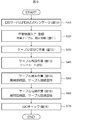
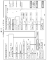
- FIG. 9 is a flowchart showing the flow of each operation in the cable construction support / management system according to the present invention, and the contents of each operation will be described with reference to FIGS.
- the construction DB server 20 is connected to each worker's PDA 50 and tablet PC 60 via a wireless LAN and a dedicated line.
- the PDA 50 and tablet PC 60 are work information for supporting work on the work permission cable from the construction DB server 20.
- the work information previously associated with the cable ID is downloaded.
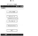
- FIG. 10 shows a download screen displayed on the PDA 50.
- the software installed for the cable construction support / management system is activated, and a download screen is displayed on the display means of the PDA 50 by selecting a download menu.
- the worker inputs the plant settings, date input, and user ID to the PDA 50 on the PDA 50 at the time of downloading.
- the user ID is input by reading the RFID tag inserted in the authentication card (name tag or the like) for each worker by the RFID reader connected to the PDA 50.
- the download soft button when the download soft button is pressed, a download request is notified to the construction DB server 20 via the wireless LAN and the dedicated line together with the plant name, date, and user ID.
- the construction DB server 20 if the worker authentication process is performed from the user ID based on the information managed by the construction management DB server 30 and it is determined that the user has the access right, the work permission is received from the design on the input date.
- the given work permission cable is searched, and work information for the searched work permission cable is transmitted to the PDA 50.
- the PDA 50 stores the work information downloaded in this way in the storage means in the PDA.
- an upload soft button is also displayed on the download screen, and when this button is pressed, work result data stored in the PDA 50 is uploaded to the construction DB server 20 and the construction management DB server 30.
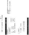
- FIG. 11 shows a screen of the PDA 50 when obtaining work information.
- the worker performs work setting of any one of cable cutting work, cable cutting work, cable laying work, cable terminal work, and cable connection work on the PDA 50, and displays a screen of desired work setting on the PDA 50.
- the screen in the case of performing cable cutting work setting is shown.
- the work information of the cable separation work for the cable actually working is obtained from the list of the work permission cables stored by downloading. Do (read).
- the read work information is displayed on the display means of the PDA 50. As a result, work instructions and work support can be provided to the worker.
- the user ID is input by reading the RFID tag inserted in the user authentication card by the RFID reader in the same manner as described above, and the cable ID is input by the RFID reader with the RFID index sticker 44 (FIG. 8 (B)) is performed by reading the RFID tag inserted.
- the terminal operation at the time of obtaining the work information is performed before each of the cable cutting work, the cable laying work, the cable terminal work, and the cable connection work, and is an operation common to each work.
- FIG. 12 shows a cable cutting work screen displayed on the PDA 50.
- the worker obtains the work information of the cable cutting work and causes the PDA 50 to display a cable cutting work screen as support information.
- cable information (cable number, design length, line type, number of cores, specification code) used for the cutting work is displayed based on the obtained work information.
- the operator selects a cable drum around which the cable to be cut is wound while referring to the cable information, and cuts the cable for the design length from the cable drum.
- a soft keyboard is displayed on the PDA 50 as shown in FIG. 12 (B), and input items (cable drum number, length, length (start and start)) Enter the end length mark) and separation date).
- An unused cable drum is wound with, for example, a 2000 m cable, and a length mark is attached to each cable.
- 215 is input as the start length mark and 70 is input as the end length mark.
- the registration button When the registration button is pressed after inputting the above input items, the user ID, cable ID, and registration date and time are stored in the storage means in the PDA together with the input items for the separation work. Also, index stickers with RFID 44 are attached to both ends of the cable cut as described above.
- FIG. 13 shows a cable laying work screen displayed on the PDA 50.
- the operator selects the process of cable laying work, reads the cable ID from the index sticker 44 with RFID attached to the cable by the RFID reader of the PDA 50, and reads the user ID from the authentication card to work the cable laying work. Information is obtained and a cable laying work screen is displayed on the PDA 50.
- the cable laying work screen shown in FIG. 13A displays cable information (cable number, design length, line type, number of cores, spec code) used for the laying work based on the obtained work information.
- cable information for example, a list of point numbers of the cable tray (cable rack)
- route information for laying the cable for example, a list of point numbers of the cable tray (cable rack)
- the worker lays the cable along the cable tray and cable rack in the building while referring to this route information.
- the operator presses the registration button on the cable laying work screen in FIG. 13A, and the user ID, cable ID, and registration date and time are stored in the storage means in the PDA together with the information on the laying work.
- FIG. 14 shows a screen of the PDA 50 when obtaining work information of cable terminal work.
- the worker displays a terminal work setting screen on the PDA 50, inputs the user ID and the cable ID, and instructs whether the cable terminal to be processed is the starting side or the landing side. In FIG. 14A, it is instructed that the cable terminal is the origin side.
- the work information of the cable terminal work on the starting point side of the cable to be actually worked is obtained from the list of the work permission cables downloaded and stored.
- RFID index stickers having different cable IDs are affixed to both ends of the cable.
- the index stickers with RFID read by the PDA 50 are provided. It is possible to specify whether the cable ID is on the origin side or the destination side of the cable (that is, associating each cable ID with the data on the origin side and the data on the destination side). it can.
- the PDA 50 displays a cable connection diagram (see FIG. 15) and the like based on the obtained cable terminal work information.
- the worker performs the cable terminal work while referring to the cable connection diagram displayed on the PDA 50.
- the cable terminal work is performed by stripping the cable at the end of the cable and attaching the terminal.
- the length of the stripping and the length of each core wire The thickness and the like can be adjusted as appropriate.
- the worker presses the registration button on the terminal work screen of FIG. 14B, and stores the user ID, cable ID, and registration date and time together with the terminal work information in the storage means in the PDA.
- FIG. 15 shows a cable connection work screen displayed on the tablet PC 60.
- the operator selects the process of the cable connection work, reads the cable ID from the index sticker with RFID 44 attached to the cable by the RFID reader of the tablet PC 60, and reads the user ID from the authentication card.
- the work information of the connection work is obtained, and the cable connection diagram is displayed on the tablet PC 60 based on the work information.
- “ku” “shi” “a” “mi” displayed corresponding to the core wire of the cable indicates the color of the core wire (black, white, red, green) and is a number. Indicates the number written on the core wire. The operator can confirm which core wire of the cable should be connected to which position of the panel and the terminal block from the cable connection diagram displayed on the tablet PC 60, and thereby the cable connection work can be correctly performed.
- the reason why the operator who performs the cable connection operation uses the tablet PC 60 without using the PDA 50 is that the tablet PC 60 has a larger screen and the cable connection diagram is easier to see. Therefore, when the screen of the cable connection diagram may be small, the PDA 50 may be used instead of the tablet PC 60.
- QC check (step S70)
- QC check Quality Control
- the cable connection worker performs a QC check while checking the check box of the check item displayed on the QC check screen.
- the checker presses a registration button on the QC check screen to register the user ID, the cable ID, and the registration date and time in the storage unit in the PDA together with the cable connection work information and the QC check result. .
- work result data (information on each work, user ID, cable ID, and registration date / time registered in the storage unit of the PDA 50 and the tablet PC 60, The check result and the like) are uploaded to the construction DB server 20 and the construction management DB server 30 and used in the respective DB servers.
- Each department and site can check the progress of work from the status of cable laying / terminal / connection work progress in real time based on work performance data, and check the remaining material and inventory of cables after separation. Employees' individual work results can be easily tabulated and understood.
- a portable terminal such as a PDA having a built-in wireless LAN communication function is used.
- the present invention is not limited to this, and a device and a cable or a cradle connected to a network are used. It is also possible to download or upload necessary information by connecting via the Internet.
- the work information for the work permission cable is downloaded in a lump and stored in the storage means in the portable terminal, and the necessary work information is read from the storage means by selecting the work process and inputting the cable ID.
- the present invention is not limited to this, and the user ID, cable ID, and work process selection are notified to the DB server for each work, and work information necessary for the work may be downloaded from the DB server for each work. Good.
- servers such as a construction DB server and a construction management DB server may be integrated.
- the index sticker with RFID is attached to the cable end, but a cable laying card on which a barcode indicating a unique cable ID is printed is attached to the cable end. Also good.
- a portable terminal such as a PDA needs to include a barcode reader.
Landscapes
- Engineering & Computer Science (AREA)
- Business, Economics & Management (AREA)
- Human Resources & Organizations (AREA)
- Strategic Management (AREA)
- Economics (AREA)
- Entrepreneurship & Innovation (AREA)
- Educational Administration (AREA)
- Game Theory and Decision Science (AREA)
- Development Economics (AREA)
- Marketing (AREA)
- Operations Research (AREA)
- Quality & Reliability (AREA)
- Tourism & Hospitality (AREA)
- Physics & Mathematics (AREA)
- General Business, Economics & Management (AREA)
- General Physics & Mathematics (AREA)
- Theoretical Computer Science (AREA)
- Management, Administration, Business Operations System, And Electronic Commerce (AREA)
Abstract
作業者は自身が携帯するPDAに、工事DBサーバから提供される作業許可ケーブルに対する作業を支援する作業情報であって、予めケーブルIDに関連づけられた作業情報をダウンロードする。PDAのRFIDタグリーダを使用して、作業者の所有するヘルメットに貼付けた氏名表示カードと一体のRFIDの情報と、ケーブル端部に貼り付けられたRFID付インデックスシールからそのケーブルのケーブルIDを読み取り、このケーブルIDに基づいて前記ダウンロードした作業情報の中から対応するケーブルに対する作業情報を取得し、PDAの表示手段に表示する。各作業者は、PDAの表示手段に表示された作業支援情報を見ながら作業を行い、作業終了時には再度、作業者のRFIDの情報を記録することで、作業と作業者情報の関連付けを異なる時間で行うことで履歴管理の信頼性を向上する。
Description
本発明はケーブル施工支援・管理システムに係り、特に大型プラント設備などでの電気ケーブルの布設工事を支援・管理する技術に関する。
図17は従来のケーブル設計施工・管理の流れを示す図である。同図に示すように電気配線設計の部分では、上流設計情報をもとにケーブルごとに必要な情報の集約を行う(ステップA)。布設経路(ケーブルを布設するケーブルトレイ(ケーブルラック)のポイントナンバー)の選定によるケーブル長さを決定するともに(ステップB)、ケーブルのサイズ・線種等の選定を行う(ステップC)。そして、ケーブルナンバーごとにステップA、B、Cの処理を行う(ステップD)。
ステップEにおいては、ケーブルのサイズ・線種・長さ・芯数の他に、発着点名称・布設経路(ケーブルトレイ等のポイントナンバー、通過する電線管のナンバーなど)の情報が揃い、これらの情報を表にしたものを配線表という。配線表をもとにケーブルの手配が行われる(ステップF)。
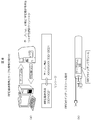
また、配線表をもとにケーブルごとに布設作業の指示・情報の授受に用いるカードを印刷する。このカードをケーブル布設用カードという。ケーブル布設用カードは、図18に示すように全ての情報が印字されている部分(半券X)と、ミシン目により切り離され、布設するケーブルの両端に貼り付けられる部分(半券Y)とを有し、半券Yは、布設と端末・接続の目印に使用される。
現地での施工・施工管理の部分では、ケーブル布設用カードに記録された情報をもとに所望のケーブルをケーブルドラムから切り分け(ステップK)、切り分けたケーブルの両端に半券Xから切り離した半券Yを貼り付ける(ステップL)。
次に、半券Xに印刷された布設経路に沿うように半券Yが貼付されたケーブルを布設する(ステップM)。半券Xの裏面には、布設チェック表が印刷されており、布設作業後に確認のチェックが行われる。続いて、ケーブル端末の処理(皮剥き、端子取付)を行い(ステップN)、その後、盤、端子台にケーブルを接続する(ステップO)。
上記ステップN,Oでの作業に必要な機器や電気盤などへのケーブル接続位置情報は、シーケンス図面をもとに作成した接続図面から取得しており、作業者は、接続作業を接続図面を見ながら行う。作業者は、接続後に接続位置が図面通りであることを確認した後、チェックマークを記録用紙に付ける(ステップP)。
管理者は、接続図面と接続された配線の照合を行い、正しい作業であることを確認した後、記録用紙に管理者の確認済みであるサインを行う。
また、従来、ケーブル布設作業管理に必要なデータ(例えば、ケーブルの品名、規格、サイズ、全長などのケーブル布設作業に必要なデータ)をケーブルにバーコードにより表示し、このバーコードをバーコードリーダを介して読み取って情報処理装置に入力するケーブル布設管理方式が提案されている(特許文献1)。また、上記バーコードに代わりRFIDを用いてケーブルを特定するシステムが提案されている。(特許文献2)
図17に示した従来のケーブル設計施工管理方式では、接続図面と記録用紙を使用するため、単独では作業の健全性は確認できず、また、接続図面も記録用紙も紙であり、作業のトレーサビリティシステムを構築する上で、電子化しにくいという欠点がある(紙をスキャンする方式では、記載された情報からの検索ができない)。
また、試験などで配線を取り外したり、復旧したりする作業は、当初の接続を行った作業者の記録用紙とは別の用紙の運用で管理されるため、最新の接続状況を把握するまでの時間遅れが常に発生することの他に、記録用紙が別であることから作業記録としての一貫性の価値は損なわれるなどの欠点がある。更に、布設・端末・接続の作業仕掛り状況から作業の進捗及び予算管理などを行う場合、切り分けた後のケーブルの残材確認・在庫確認などを行う場合には、情報が工程の各所に散在しているため、常に時間遅れによる誤差がでやすいという欠点がある。
一方、特許文献1には、ケーブルに表示されたバーコード(ケーブル布設作業管理に必要なデータ)を読み取ることにより、人的エラーはなく所要のデータを情報処理装置に入力する記載や、入力されたデータをもとにケーブル布設の作業を検討して管理する記載があるが、現場でのケーブル布設作業を支援したり、最新の接続状況等を管理する記載はない。
また、特許文献2にはバーコードに代わりRFIDを用いて設計部門から現場での各作業者に対してケーブル布設作業の支援、作業終了の確認記録の電子化による作業及び確認作業の省力化・迅速化を図るとともに、作業者の認証、作業の許可、作業結果の報告、チェックの報告などの情報授受の信頼性の向上(トレーサビリティ確保)を図る試みがなされている。しかし、作業許可されていない(または公的資格のない)作業者が、許可されている作業者に成りすましてなされる不正作業を防止する機能が無く、システム上のセキュリティ改良の余地が残されていた。
本発明はこのような事情に鑑みてなされたもので、作業者がもつ作業者IDと、サーバからダウンロードされた作業の許可者IDとの一致に基づいて作業情報を表示することにより、作業の省力化・迅速化を図ると共に、無許可者の不正作業を防止した、セキュリティの高い、ケーブル施工・管理システムを提供することを目的とする。
作業現場において個々の作業者に配布されるヘルメットに貼付けされる会社名、氏名、作業資格、血液型等の情報を表示する氏名表示カードに、作業者情報(氏名表示カードの情報の他、ケーブル接続作業の許可の有無、資格の有無)を記録したRFIDを一体にして貼付け、作業開始時及び終了時に作業者情報をPDAに備わっているRFIDリーダーで読取り、作業者情報を記録することで、作業の信頼性と履歴管理の徹底を図ることが可能となる。
前記目的を達成するために、請求項1に係る発明は、作業者が携帯する携帯端末と、前記携帯端末との間でネットワークを介して必要な情報の授受を行うサーバとからなり、固有のケーブル識別情報が記録されたケーブル布設用カードが取り付けられたケーブルを、予め設計された経路に沿って接続する作業を支援するケーブル施工支援・管理システムにおいて、
前記携帯端末は、
前記作業を行う作業者のヘルメットに貼付され作業者IDを含む作業者情報が記録された作業者認証カードから該作業者情報を読み取る作業者読取手段と、
読取られた作業者情報を記憶する第1記憶手段と
前記ケーブル布設用カードからケーブル識別情報を読み取るケーブル読取手段と、
前記サーバから提供される作業許可ケーブルの作業を支援する支援情報と、作業許可者に関する許可者IDを含む作業者情報からなる作業情報を、予めケーブル識別情報に関連づけてダウンロードして記憶する第2記憶手段と、
前記ケーブル読取手段によって読み取られたケーブル識別情報に基づいて、前記第2記憶手段から該当するケーブルに対する作業情報を取得する作業情報取得手段と、
前記第1記憶手段に記憶された作業者情報の作業者IDと、前記第2記憶手段に記憶された作業者情報の許可者IDを比較して一致する場合、表示許可情報を出力する照合手段と、
前記表示許可情報によって前記作業情報取得手段で取得された作業情報を表示する表示手段を有し、
前記サーバは、
前記施設内に布設される各ケーブルの作業を支援する支援情報と、作業許可者に関する許可者IDを有する作業者情報を、各ケーブル識別情報に関連づけて記憶する第3記憶手段と、
前記携帯端末からのダウンロード要求に応じて前記第3記憶手段から該当するケーブルの作業情報を前記第3記憶手段から抽出する抽出手段と、
前記抽出手段によって抽出された作業情報をケーブル識別情報とともに前記携帯端末に提供する作業情報提供手段を有することを特徴としている。
即ち、各作業者は、自身が携帯する携帯端末に、サーバから提供される作業許可ケーブルに対する作業を支援する作業情報であって、予めケーブル識別情報に関連づけられた作業情報をダウンロードする。
そして、携帯端末の読取手段を使用してケーブルの端部に取り付けられたケーブル布設用カードからそのケーブルのケーブル識別情報を読み取り、このケーブル識別情報に基づいて前記ダウンロードした作業情報の中から対応するケーブルに対する作業情報を取得し、また、作業者自身のヘルメットに貼り付けられた作業者認証カードから作業者自身に関する作業者IDを読み出し、前記作業情報に含まれる作業許可者IDと照合し、合致した場合のみ、携帯端末の表示手段に表示する。これにより、各作業者は、表示手段に表示された作業情報を見ながら必要な作業を行うことができる。
そして、携帯端末の読取手段を使用してケーブルの端部に取り付けられたケーブル布設用カードからそのケーブルのケーブル識別情報を読み取り、このケーブル識別情報に基づいて前記ダウンロードした作業情報の中から対応するケーブルに対する作業情報を取得し、また、作業者自身のヘルメットに貼り付けられた作業者認証カードから作業者自身に関する作業者IDを読み出し、前記作業情報に含まれる作業許可者IDと照合し、合致した場合のみ、携帯端末の表示手段に表示する。これにより、各作業者は、表示手段に表示された作業情報を見ながら必要な作業を行うことができる。
請求項2に係る発明は、作業者が携帯する携帯端末と、前記携帯端末との間でネットワークを介して必要な情報の授受を行うサーバとからなり、固有のケーブル識別情報が記録されたケーブルカードが取り付けられたケーブルを、予め設計された経路に沿って接続する作業を支援するケーブル施工支援・管理システムにおいて、
前記携帯端末は、
前記作業を行う作業者のヘルメットに貼付され作業者IDを含む作業者情報が記憶された作業者認証カードから該作業者情報を読み取る作業者読取手段と、
読取られた作業者情報を記憶する第1記憶手段と
前記ケーブルカードからケーブル識別情報を読み取るケーブル読取手段と、
前記ケーブル読取手段によって読み取られたケーブル識別情報に基づいて、該当ケーブルの作業に関する支援情報と作業許可の許可者IDを有する作業者情報を前記サーバから取得する作業情報取得手段と、
前記第1の記憶手段に記憶された作業者IDと前記作業情報取得手段で取得された許可者IDを比較し一致する場合、表示許可情報を出力する照合手段と、
前記照合手段からの表示許可情報によって前記作業情報取得手段で取得された作業情報を表示する表示手段を有し、
前記サーバは、
前記施設内に布設される各ケーブルの作業を支援する支援情報と、作業許可者に関する許可者IDを有する作業情報を、各ケーブル識別情報に関連づけて記憶する第3記憶手段と、
前記携帯端末から受信するケーブル識別情報に基づいて該当するケーブルの作業情報を前記第3の記憶手段から抽出する抽出手段と、
前記抽出手段によって抽出された作業情報を前記携帯端末に提供する作業情報提供手段を有することを特徴としている。
請求項1に係る発明では、最初にサーバから作業許可ケーブルに対する作業を支援する作業情報をダウンロードするようにしたが、請求項2に係る発明は、携帯端末のケーブル読取手段を使用してケーブルに取り付けられたケーブル布設用カードからケーブル識別情報を読み取ると、サーバから前記読み取ったケーブル識別情報に基づいて対応するケーブルの作業情報を取得する点で、請求項1に係る発明と相違している。
請求項3に示すように請求項1又は2に記載のケーブル施工支援・管理システムにおいて、前記ケーブル布設用カードはケーブルの両端部に取り付けられ、前記ケーブルの両端部に取り付けられるケーブル布設用カードはそれぞれ異なるケーブル識別情報が記録されていることを特徴としている。ケーブルの両端は、それぞれ異なる種類の盤、端子台に接続される場合が多く、ケーブルの端部ごとの接続に関する作業情報を取得することができる。
請求項4に示すように請求項1から3のいずれかに記載のケーブル施工支援・管理システムにおいて、前記ケーブル布設用カードは、RFIDタグが漉き込まれたカード、又はバーコードが印刷されたカードであり、前記携帯端末のケーブル読取手段は、RFIDタグリーダ、又はバーコードリーダであることを特徴としている。
請求項5に示すように請求項1から4のいずれかに記載のケーブル施工支援・管理システムにおいて、前記携帯端末は、少なくとも前記サーバへのアクセス許可を受けるための作業者の認証情報として作業者情報を前記作業者読取手段で入力することを特徴としている。これにより、不正なアクセスを防止することができるとともに、アクセスした作業者のアクセス権に応じて該作業者が必要とする作業情報のみを送ることも可能である。
請求項5に示すように請求項1から4のいずれかに記載のケーブル施工支援・管理システムにおいて、前記携帯端末は、少なくとも前記サーバへのアクセス許可を受けるための作業者の認証情報として作業者情報を前記作業者読取手段で入力することを特徴としている。これにより、不正なアクセスを防止することができるとともに、アクセスした作業者のアクセス権に応じて該作業者が必要とする作業情報のみを送ることも可能である。
請求項6に示すように、請求項5に記載のケーブル施工支援・管理システムにおいて、前記作業者の認証情報は、作業者毎の認証カードに漉き込まれたRFIDタグに記録され、且つ、該RFIDは作業者の所有するヘルメットに貼付される氏名表示カードと一体とされ、前記作業者読取手段は、RFIDタグリーダであることを特徴としている。なお、RFIDと氏名表示カードが一体とされるということは、故意に両者が分離された場合、その分離の行為が物理的に氏名表示カードに現れることをいう。例えば、氏名表示カードとRFIDをフィルムで覆い、分離した場合にはフィルムに破損が生じ、外観でセキュリティ上の問題が生じていることを確認できる。
請求項7に示すように、請求項5又は6に記載のケーブル施工支援・管理システムにおいて、前記携帯端末は、前記支援情報に対応する作業の終了を登録する登録手段を備え、前記登録手段による作業の終了時又はアップロードの指示入力時に、前記ケーブル識別情報、登録日時、及び作業者の認証情報を前記サーバにアップロードすることを特徴としている。これにより、どの作業者によって、どのような作業がいつ終了したか等の作業履歴を容易に管理することができる。
請求項8に示すように、請求項1から7のいずれかに記載のケーブル施工支援・管理システムにおいて、前記支援情報は、ケーブルドラムから設計された長さのケーブルを切り分けるケーブル切分け作業、前記切り分けられたケーブルを設計された経路に沿って布設するケーブル布設作業、前記布設されたケーブルの両端のケーブル端末を接続可能に処理する端末処理作業、端末処理されたケーブル端末を盤、端子台に接続するケーブル接続作業、及び前記接続されたケーブルのチェック作業に関する情報のうちの1以上の作業を含むことを特徴としている。
請求項9に示すように、請求項8に記載のケーブル施工支援・管理システムにおいて、前記ケーブル切分け作業に関する支援情報は、ケーブルを特定するための情報、及びケーブルの設計長を含むことを特徴としている。
請求項10に示すように、請求項8又は9に記載のケーブル施工支援・管理システムにおいて、前記ケーブル布設作業に関する支援情報は、ケーブルを布設する経路情報を含むことを特徴としている。ケーブルを布設する経路情報は、例えば、ケーブルトレイ(ケーブルラック)のポイントナンバーで示される。
請求項11に示すように請求項8から10のいずれかに記載のケーブル施工支援・管理システムにおいて、端末処理作業、ケーブル接続作業、及びチェック作業に関する支援情報は、ケーブル接続図を含むことを特徴としている。
請求項12に示すように請求項11に記載のケーブル施工支援・管理システムにおいて、前記チェック作業に関する支援情報は、チェックリストを含むことを特徴としている。
本発明によれば、携帯端末で作業情報を表示することにより、作業の省力化・迅速化を図ると共に、無許可作業者の不正使用を防止してセキュリティを高めることができる。
以下、添付図面に従って本発明に係るケーブル施工支援・管理システムの実施の形態について説明する。
<システムの概略構成>
図1はケーブル施工支援・管理システムの概略構成図である。図1において、ケーブル施工支援・管理システムは、作業者が携帯する携帯端末(PDA)80と、前記携帯端末80との間でネットワーク94を介して必要な情報の授受を行うサーバ90とからなり、固有のケーブル識別情報が記録されたケーブル布設用カード96、97が取り付けられたケーブル95から構成される。
<システムの概略構成>
図1はケーブル施工支援・管理システムの概略構成図である。図1において、ケーブル施工支援・管理システムは、作業者が携帯する携帯端末(PDA)80と、前記携帯端末80との間でネットワーク94を介して必要な情報の授受を行うサーバ90とからなり、固有のケーブル識別情報が記録されたケーブル布設用カード96、97が取り付けられたケーブル95から構成される。
前記携帯端末80は、前記作業を行う作業者のヘルメット87に貼付され作業者IDを含む作業者情報(氏名表示カードの情報の他、ケーブル接続作業の許可の有無、資格の有無)が記録された作業者認証カード87aのRFIDから該作業者情報を読み取る作業者読取手段86と、読取られた作業者情報を記憶する第1記憶手段84と、前記ケーブル布設用カード96,97のRFIDからケーブル識別情報を読み取るケーブル読取手段81と、前記サーバ90から提供される作業許可ケーブルの作業を支援する支援情報と、作業許可者に関する許可者IDを含む作業者情報からなる作業情報を、予めケーブル識別情報に関連づけてダウンロードして記憶する第2記憶手段83と、前記ケーブル読取手段81によって読み取られたケーブル識別情報に基づいて、前記第2記憶手段83から該当するケーブルに対する作業情報を取得する作業情報取得手段82と、前記第1記憶手段84に記憶された作業者情報の作業者IDと、前記第2記憶手段83に記憶された作業者情報の許可者IDを比較して一致する場合、表示許可情報を出力する照合手段85と、前記表示許可情報によって前記作業情報取得手段82で取得された作業情報を表示する表示手段89を有している。88は前記表示許可情報と作業者情報とのANDをとって作業者情報を表示手段89に出力するゲートである。
前記サーバ90は、前記施設内に布設される各ケーブルの作業を支援する支援情報と、作業許可者に関する許可者IDを有する作業者情報を、各ケーブル識別情報に関連づけて記憶する第3記憶手段91と、前記携帯端末80からのダウンロード要求に応じて前記第3記憶手段91から該当するケーブルの作業情報を前記第3記憶手段から抽出する抽出手段92と、前記抽出手段92によって抽出された作業情報をケーブル識別情報とともに前記携帯端末80に提供する作業情報提供手段93を有する。
上記構成(請求項1に係る発明)では、最初に(予め)サーバ90から作業許可ケーブルに対する作業を支援する作業情報を第2記憶手段83にダウンロードする構成としている。他の構成(請求項2に係る発明)として、携帯端末のケーブル読取手段81を用いてケーブル布設用カード96,97からケーブル識別情報を読み取ったときに、サーバ90から読み取られたケーブル識別情報に基づいて対応するケーブルの作業情報を作業情報取得手段81にダウンロードする構成としても良い。
この場合、図1において、携帯端末80に第2記憶手段83が内蔵されず、破線で示すようにサーバ90から作業情報を作業情報取得手段81にダウンロードし、作業情報取得手段81からの作業情報を破線で示すように照合手段85で入力して、第1記憶手段84からの作業者情報と比較するように構成される。
図2は、ケーブルの布設作業を行う作業者のヘルメット87に貼付される作業者認証カード87aと、貼付されたヘルメット87の外観を示す図である。図3は、ヘルメット上の作業者認証カードの作業者情報を読取に伴う作業の概略流れを示すフロー図である。
図3のステップ(S)101で、PDA80でのヘルメット上の作業者認証カード87aのRFID87b内の作業者IDを含む作業者情報を読取り、S102で予めサーバからダウンロードされて第1記億手段に記憶された許可者IDを含む作業者情報と照合する。照合の結果の一致に基づいてS103でログインし、S104でPDAに作業者IDを記録する。次いで、表示された作業情報の中の作業の支援情報を見ながらS105~S107でケーブルの布設に必要な作業A~Cを行う。ここで、表示された作業情報の作業の支援情報とは、ケーブル切分け作業の画面や、ケーブル情報(ケーブルナンバー、設計長、線種、芯数、スペックコード)の画面などである。
全作業が終了した後、S108で再度ヘルメット上の作業者認証カード87aのRFIDの作業者情報を読取り、S109で再度PDAに作業者情報の作業者IDを記録する。この一連のフローにより、正規の作業者による作業がなされ、作業者とその結果が記録される。作業と作業者情報の関連付けを異なる時間で行うことで履歴管理の信頼性を向上する。
上記のように作業現場において、個々の作業者に配布されるヘルメットに貼付けされる会社名、氏名、作業資格、血液型等の情報を表示する氏名表示カード(作業者認証カード)に、作業者情報(氏名表示カードの印字情報に加え、ケーブル接続作業の許可の有無、資格の有無)を記録したRFIDを一体にして貼付け、作業開始時及び終了時に作業者情報をPDAに備わっているRFIDリーダーで読取り、作業者情報を記録することで、作業の信頼性(セキュリティー向上)と履歴管理の徹底を図ることが可能となる。
また、各作業者の携帯端末でケーブルに取り付けられたケーブル布設用カードからケーブル識別情報を読み取ることで、そのケーブルに対する作業情報を取得して携帯端末に表示させることができ、各作業者は、この表示された作業の支援情報を見ながら必要な作業を容易かつ確実に行うことができる。
また、携帯端末に作業者情報を入力するとともに、作業の終了を登録することにより、サーバ側では、作業履歴を容易に管理することができる。作業及び確認作業の省力化・迅速化を図ると共に、無許可作業者の不正使用を防止した、
図4は本発明に係るケーブル施工支援・管理システムの全体構成図である。このケーブル施工支援・管理システムは、主としてケーブル施工を行う事業者の社内などに設置される設計データベース・サーバ(DBサーバ)10と、工事DBサーバ20と、施工管理DBサーバ30と、原子力発電所などの大型プラント設備の現地事務所に設置されるパソコン40、プリンタ42と、各現場の作業者が携帯する携帯端末(PDA(携帯情報端末)50、タブレットPC60)と、これらを接続するネットワークとによって構成されている。ここで、サーバ10、20、30は図1のサーバ90に相当し、PDA50は図1のPDA80に相当する。
図4は本発明に係るケーブル施工支援・管理システムの全体構成図である。このケーブル施工支援・管理システムは、主としてケーブル施工を行う事業者の社内などに設置される設計データベース・サーバ(DBサーバ)10と、工事DBサーバ20と、施工管理DBサーバ30と、原子力発電所などの大型プラント設備の現地事務所に設置されるパソコン40、プリンタ42と、各現場の作業者が携帯する携帯端末(PDA(携帯情報端末)50、タブレットPC60)と、これらを接続するネットワークとによって構成されている。ここで、サーバ10、20、30は図1のサーバ90に相当し、PDA50は図1のPDA80に相当する。
社内の設計DBサーバ10、工事DBサーバ20、施工管理DBサーバ30と、現地事務所のパソコン40とはそれぞれ専用回線によって接続されている。また、PDA50、タブレットPC60は、無線LANによる通信機能を内蔵しており、建屋のフロアーごと、あるいは所定のエリアごとに設置されている無線アクセスポイント70を通じて専用回線に接続されている各DBサーバ等と通信することができるようになっている。
設計DBサーバ50には、ケーブルに関する情報(ケーブル情報、機器情報、仕様、ケーブルルート)や、ケーブル接続図に関する情報(端子台情報、ケーブル情報、機器情報、パターン図)等が管理されており、設計部門で許可した工事用の情報が工事DBサーバ20に渡される。
また、設計部門に設置されたパソコン(図示せず)には、ケーブル接続図自動生成プログラムが格納されており、このパソコンは、図5に示すようにローカル機器ごとのパターン図とケーブル情報とに基づいてECWD方式(Elementary control wiring diagrams)などのケーブル接続図を自動生成する。また、図6に示すようにパソコンは、上記のようにして自動生成されたケーブル接続図を編集する機能を有している。設計DBサーバ10では、このケーブル接続図の情報も管理している。
施工管理DBサーバ30では、従業者(作業者)の認証情報(ユーザID)に基づいて従業者の個人情報等を管理するとともに、ケーブル施工の実績データを管理する。ここで、従業者とは作業者を含む従業者であり、作業者の場合の認証情報は、「許可者ID」と「作業資格」を含む作業者情報である。
現地事務所のパソコン40は、プリンタ42にケーブルナンバーの印刷情報を出力し、ケーブル布設用カード上にケーブルナンバーを印刷させる。尚、ケーブル布設用カードには、予めRFIDタグ(RFID:Radio Frequency Identification)が漉き込まれており、このRFIDタグには、ケーブルナンバーと一対一に対応するユニークなケーブル識別情報(ケーブルID)が記録されている。
また、パソコン40は、プリンタ42に作業者の作業者情報の印刷情報を出力し、作業者認証カード87a上に作業者情報を印刷させる。尚、作業者認証カード87aには、予めRFIDタグ87bが漉き込まれており、このRFIDタグには、印刷された作業者情報に対応したユニークな情報が記録されている。作業者情報としては、会社名、氏名、作業資格、血液型、作業者IDなどから構成される。印刷および情報が記録された作業者認証カード87aは、該当作業者の所有するヘルメット87に貼付さる。
パソコン40はケーブルIDを受け取ることにより、又はプリンタ42から出力されたケーブル布設用カードからケーブルIDを読み取ることにより、ケーブルナンバーとケーブルIDとの関連づけを行い、その関連づけた情報を工事DBサーバ20に送信する。工事DBサーバ20では、パソコン40から送られたケーブルナンバーとケーブルIDとを関連づけた情報と、ケーブルナンバーごとに管理している各現場での作業情報とをリンクさせる。
また、パソコン40は作業者情報を受け取ることにより、又はプリンタ42から出力された作業者認証カード87aから作業者情報を読み取ることにより、ケーブルナンバーと作業者情報との関連づけを行い、その関連づけた情報を施工管理DBサーバ30に送信する。施工管理DBサーバ30では、パソコン40から送られたケーブルナンバーと作業者情報と、ケーブルナンバーごとに管理している各現場での作業情報とをリンクさせる。
PDA50、タブレットPC60は、端末として動作するためのオペレーティングシステム(OS)、周辺機器のデバイスドライバ、及び本発明に係るケーブル施工支援・管理システムに適用するためのソフトウエアが記憶される記憶手段と、液晶表示器等の表示手段と、タッチパネル等の入力手段とを有している。また、PDA50、タブレットPC60のコネクタ又はスロットには、RFIDタグからケーブルIDを読み取るためのRFIDリーダが取り付けられている。
<本発明によるケーブル設計施工・管理の流れ>
図7は本発明によるケーブル設計施工・管理の流れを示す図である。尚、図7において、図17の従来のケーブル設計施工・管理の流れに示したステップに対応するステップには同一のステップ番号が付されている。
図7は本発明によるケーブル設計施工・管理の流れを示す図である。尚、図7において、図17の従来のケーブル設計施工・管理の流れに示したステップに対応するステップには同一のステップ番号が付されている。
まず、図18に示した従来の紙ベースのケーブル布設用カード(半券X,半券Y)の代わりに、RFIDタグが漉き込まれたケーブル布設用カード(半券Y)を発行する。各現場で作業者が携帯するPDA50、タブレットPC60は、工事DBサーバ20から前記作業情報をネットワークを通じてダウンロードできるようになっている。
ステップKでは、RFIDタグを読み取ることにより、ケーブルナンバーに対応するケーブルをケーブルドラムから切り分けるための作業情報を取得する。ステップLでは、切り分けたケーブルの両端に、RFIDタグが漉き込まれた半券Yを貼り付ける。ケーブルを布設する現場では、PDA50により半券YからケーブルIDを読み取ることにより、布設経路情報を取得する(ステップM)。作業者は、この布設経路情報に基づいて布設経路に沿うようにケーブルの布設作業を行う。
ステップNでは、ケーブル端末の処理(皮剥き、端子取付)を行うが、このケーブル端末の処理に必要なケーブル接続図は、PDA50により半券YからケーブルIDを読み取ることにより、ケーブル接続図を取得する。同様に、ステップOでの盤、端子台にケーブルを接続するケーブル接続作業、ステップPでのケーブル接続チェック時には、タブレットPC60により半券YからケーブルIDを読み取ることにより、ケーブル接続図やチェックリストを取得する。
即ち、本発明に係るシステムでは、従来の全ての情報が印字されて部分(半券X)が不要となり、また、紙ベースでのケーブル接続図が不要となる。また、各作業での実績データの入力等も携帯端末等で行うことができ、実績を記入するための書類等が不要となる。
<RFID製造番号とケーブル情報の突き合わせ>
図8(A)に示すように、現地事務所に設置されたパソコン40から1本分のケーブルナンバーをプリンタ42に入力すると、プリンタ42は、ユニークなケーブルID(RFID固有のID)が記録されたRFIDタグが漉き込まれたケーブル布設用カード(以下、「RFID付インデックスシール」という)を2枚プリント出力する。
図8(A)に示すように、現地事務所に設置されたパソコン40から1本分のケーブルナンバーをプリンタ42に入力すると、プリンタ42は、ユニークなケーブルID(RFID固有のID)が記録されたRFIDタグが漉き込まれたケーブル布設用カード(以下、「RFID付インデックスシール」という)を2枚プリント出力する。
図8(B)に示すように2枚のRFID付インデックスシール44は、ケーブルの両端(図8(B)では一端のみを示している)にそれぞれ貼り付けられる。尚、RFID付インデックスシールに漉き込まれているRFID固有のIDは、例えば、製造時に付けられたRFID製造番号であり、ケーブルごとに発行される2枚のRFID付インデックスシールにそれぞれ漉き込まれているRFIDタグは、それぞれ異なるIDが記録されている。
プリンタ42は、RFID付インデックスシールにケーブルナンバーをプリントし、また、ケーブルナンバーに対応してプリントした2枚のRFID付インデックスシールに漉き込まれているRFID固有のID(以下、「ケーブルID」という)をパソコン40に通知する。尚、パソコン40にRFIDリーダを設け、プリント出力されたRFID付インデックスシールからその都度、ケーブルIDを読み取らせるようにしてもよい。
パソコン40は、ケーブル情報(ケーブルナンバー)と、そのケーブルナンバーに対応してプリント出力された2枚のRFID付インデックスシールのRFIDタグに記録されたケーブルIDとの関連づけを行い、この関連づけした情報を工事DBサーバ20に送る。
このようにケーブルナンバーとケーブルIDとの関連づけを行うことにより、後述するようにRFIDタグからケーブルIDを読み取ることによりケーブルナンバー等に関連づけられているケーブルに関連する各種の情報を、工事DBサーバ20から取得することができるようにしている。
<ケーブル施工支援・管理システムでの作業内容>
図9は本発明に係るケーブル施工支援・管理システムでの各作業の流れを示すフローチャートであり、各作業内容等を図10から図16を参照しながら説明する。
図9は本発明に係るケーブル施工支援・管理システムでの各作業の流れを示すフローチャートであり、各作業内容等を図10から図16を参照しながら説明する。
[DBサーバとPDAとのリンケージ(ステップS10)]
工事DBサーバ20と各作業者のPDA50、タブレットPC60とは、無線LAN及び専用回線を介して接続され、PDA50、タブレットPC60は、工事DBサーバ20から作業許可ケーブルに対する作業を支援する作業情報であって、予めケーブルIDに関連づけられた作業情報をダウンロードする。
工事DBサーバ20と各作業者のPDA50、タブレットPC60とは、無線LAN及び専用回線を介して接続され、PDA50、タブレットPC60は、工事DBサーバ20から作業許可ケーブルに対する作業を支援する作業情報であって、予めケーブルIDに関連づけられた作業情報をダウンロードする。
図10はPDA50に表示されるダウンロード画面を示す。同図に示すように、PDA50において、ケーブル施工支援・管理システム用にインストールされたソフトウエアを起動させ、ダウンロードのメニューを選択することによりPDA50の表示手段にダウンロード画面を表示させる。
作業者は、ダウンロード時にPDA50上でプラントの設定、日付の入力、及びユーザIDをPDA50に入力する。尚、ユーザIDの入力は、PDA50に接続されたRFIDリーダによって作業者毎の認証カード(名札等)に漉き込まれているRFIDタグを読み取ることにより行われる。
そして、ダウンロードのソフトボタンを押すと、プラント名、日付、及びユーザIDとともにダウンロード要求が無線LAN、専用回線を経由して工事DBサーバ20に通知される。工事DBサーバ20では、施工管理DBサーバ30で管理されている情報に基づいてユーザIDから作業者の認証処理を行い、アクセス権を有すると判断すると、入力された日付において、設計から作業許可が与えられている作業許可ケーブルを検索し、検索した作業許可ケーブルに対する作業情報をPDA50に送信する。PDA50は、このようにしてダウンロードした作業情報をPDA内の記憶手段に記憶させる。
尚、ダウンロード画面には、アップロードのソフトボタンも表示されており、このボタンが押されると、PDA50に記憶されている作業実績データが工事DBサーバ20、施工管理DBサーバ30にアップロードされる。
[作業情報入手(ステップS20)]
図11は作業情報を入手するときのPDA50の画面を示す。作業者は、PDA50上でケーブル切分け作業、ケーブル切分け作業、ケーブル布設作業、ケーブル端末作業、又はケーブル接続作業のいずれかの作業設定を行い、PDA50に所望の作業設定の画面を表示させる。尚、図11では、ケーブル切分け作業設定を行う場合の画面が示されている。
図11は作業情報を入手するときのPDA50の画面を示す。作業者は、PDA50上でケーブル切分け作業、ケーブル切分け作業、ケーブル布設作業、ケーブル端末作業、又はケーブル接続作業のいずれかの作業設定を行い、PDA50に所望の作業設定の画面を表示させる。尚、図11では、ケーブル切分け作業設定を行う場合の画面が示されている。
続いて、PDA50にユーザIDとケーブルIDとを入力し、OKボタンを押すことにより、前記ダウンロードして記憶した業許可ケーブルの一覧から実際に作業を行うケーブルに対するケーブル切分け作業の作業情報を入手する(読み出す)。この読み出された作業情報は、PDA50の表示手段に表示される。これにより、作業者に対して作業指示、作業の支援が可能になる。
ここで、ユーザIDの入力は、上記と同様にRFIDリーダによってユーザの認証カードに漉き込まれているRFIDタグを読み込むことによって行い、ケーブルIDの入力は、RFIDリーダによってRFID付インデックスシール44(図8(B)参照)に漉き込まれているRFIDタグを読み込むことによって行う。
尚、この作業情報入手時の端末操作は、ケーブル切分け作業、ケーブル布設作業、ケーブル端末作業、ケーブル接続作業の各作業前に行われ、各作業に共通している操作である。
[ケーブル切分け作業(ステップS30)]
図12はPDA50に表示されるケーブル切分け作業画面を示す。作業者は、上述したようにケーブル切分け作業の作業情報を入手し、PDA50に支援情報としてのケーブル切分け作業画面を表示させる。図12(A)に示すケーブル切分け作業画面には、入手した作業情報に基づいて切分け作業に利用されるケーブル情報(ケーブルナンバー、設計長、線種、芯数、スペックコード)が表示される。作業者は、このケーブル情報を参照しながら切り分けるケーブルが巻回されているケーブルドラムを選択し、このケーブルドラムから設計長分のケーブルを切り分ける。
図12はPDA50に表示されるケーブル切分け作業画面を示す。作業者は、上述したようにケーブル切分け作業の作業情報を入手し、PDA50に支援情報としてのケーブル切分け作業画面を表示させる。図12(A)に示すケーブル切分け作業画面には、入手した作業情報に基づいて切分け作業に利用されるケーブル情報(ケーブルナンバー、設計長、線種、芯数、スペックコード)が表示される。作業者は、このケーブル情報を参照しながら切り分けるケーブルが巻回されているケーブルドラムを選択し、このケーブルドラムから設計長分のケーブルを切り分ける。
この切分け作業が終了すると、図12(B)に示すようにPDA50にソフトキーボードを表示させ、切分け作業での作業結果を示す入力項目(ケーブルドラムのドラムナンバー、長さ、レングス(スタートとエンドのレングスマーク)、切分け日)の入力を行う。尚、未使用のケーブルドラムには、例えば2000mのケーブルが巻回されており、このケーブルには、1mごとにレングスマークが付されている。この実施の形態では、スタートのレングスマークとして215が入力され、エンドのレングスマークとして70が入力されている。これにより、ケーブルドラムから145m(=215-70)のケーブルが切り分けられ、また、ケーブルドラムの残りのケーブル長が70mであることが分かる。
上記入力項目を入力した後、登録ボタンを押すと、切分け作業の入力項目とともに、ユーザID、ケーブルID、及び登録日時がPDA内の記憶手段に記憶される。また、上記のようにして切り分けられたケーブルの両端には、それぞれRFID付インデックスシール44が貼り付けられる。
[ケーブル布設作業(ステップS40)]
図13はPDA50に表示されるケーブル布設作業画面を示す。作業者は、ケーブル布設作業の処理選択を行い、PDA50のRFIDリーダによってケーブルに貼り付けられたRFID付インデックスシール44からケーブルIDを読み取るとともに、認証カードからユーザIDを読み取ることによりケーブル布設作業の作業情報を入手し、PDA50にケーブル布設作業画面を表示させる。
図13はPDA50に表示されるケーブル布設作業画面を示す。作業者は、ケーブル布設作業の処理選択を行い、PDA50のRFIDリーダによってケーブルに貼り付けられたRFID付インデックスシール44からケーブルIDを読み取るとともに、認証カードからユーザIDを読み取ることによりケーブル布設作業の作業情報を入手し、PDA50にケーブル布設作業画面を表示させる。
図13(A)に示すケーブル布設作業画面には、入手した作業情報に基づいて布設作業に使用されるケーブル情報(ケーブルナンバー、設計長、線種、芯数、スペックコード)が表示され、図13(B)に示すケーブル布設作業画面(次頁の画面)には、ケーブルを布設する経路情報(例えば、ケーブルトレイ(ケーブルラック)のポイントナンバーの一覧)が表示される。
作業者は、この経路情報を参照しながらケーブルを建屋内のケーブルトレイ、ケーブルラックに沿って布設する。この布設作業が終了すると、作業者は、図13(A)のケーブル布設作業画面上の登録ボタンを押し、布設作業の情報とともに、ユーザID、ケーブルID、及び登録日時をPDA内の記憶手段に記憶させる。
[ケーブル端末作業(ステップS50)]
図14はケーブル端末作業の作業情報を入手するときのPDA50の画面を示す。作業者は、PDA50に端末作業設定の画面を表示させ、ユーザIDとケーブルIDとを入力するとともに、処理しようとするケーブル端末が発点側、着点側のいずれであるかを指示する。尚、図14(A)では、ケーブル端末が発点側であることが指示されている。
図14はケーブル端末作業の作業情報を入手するときのPDA50の画面を示す。作業者は、PDA50に端末作業設定の画面を表示させ、ユーザIDとケーブルIDとを入力するとともに、処理しようとするケーブル端末が発点側、着点側のいずれであるかを指示する。尚、図14(A)では、ケーブル端末が発点側であることが指示されている。
続いて、OKボタンを押すことにより、前記ダウンロードして記憶した業許可ケーブルの一覧から実際に作業を行うケーブルの発点側におけるケーブル端末作業の作業情報を入手する。
また、ケーブルの両端には、それぞれ異なるケーブルIDを有するRFID付インデックスシールが貼り付けられているが、上記発点側又は着点側の指示を行うことにより、PDA50によって読み取ったRFID付インデックスシールのケーブルIDが、ケーブルの発点側のものか、着点側のものかを特定すること(即ち、各ケーブルIDと、発点側のデータ、着点側のデータとの関連づけを行うこと)ができる。
PDA50には、前記入手したケーブル端末作業の作業情報に基づいてケーブル接続図(図15参照)等が表示される。作業者は、PDA50に表示されたケーブル接続図等を参照しながらケーブル端末作業を行う。ケーブル端末作業としては、図8(B)に示すようにケーブル端部でのケーブル皮剥き、端子取付けが行われるが、ケーブル接続図等を参照することにより、皮剥の長さ、各芯線の長さなどを適宜調節することができる。
この端末処理が終了すると、作業者は、図14(B)の端末作業画面上の登録ボタンを押し、端末作業の情報とともに、ユーザID、ケーブルID、及び登録日時をPDA内の記憶手段に記憶させる。
[ケーブル接続作業(ステップS60)]
図15はタブレットPC60に表示されるケーブル接続作業画面を示す。作業者は、ケーブル接続作業の処理選択を行い、タブレットPC60のRFIDリーダによってケーブルに貼り付けられたRFID付インデックスシール44からケーブルIDを読み取らせるとともに、認証カードからユーザIDを読み取らせることにより、ケーブル接続作業の作業情報を入手させ、この作業情報に基づいてタブレットPC60にケーブル接続図を表示させる。
図15はタブレットPC60に表示されるケーブル接続作業画面を示す。作業者は、ケーブル接続作業の処理選択を行い、タブレットPC60のRFIDリーダによってケーブルに貼り付けられたRFID付インデックスシール44からケーブルIDを読み取らせるとともに、認証カードからユーザIDを読み取らせることにより、ケーブル接続作業の作業情報を入手させ、この作業情報に基づいてタブレットPC60にケーブル接続図を表示させる。
図15に示すケーブル接続図において、ケーブルの芯線に対応して表示されている「ク」「シ」「ア」「ミ」は、芯線の色(黒、白、赤、緑)を示し、数字は、芯線に記入されている番号を示す。作業者は、タブレットPC60に表示されたケーブル接続図からケーブルのどの芯線を盤、端子台のどの位置に接続すべきかを確認することができ、これによりケーブル接続作業を正しく行うことができる。
尚、ケーブル接続作業を行う作業者が、PDA50を使用せずにタブレットPC60を使用する理由は、タブレットPC60の方が画面が大きく、ケーブル接続図が見やすいからである。従って、ケーブル接続図の画面が小さくてもよい場合には、タブレットPC60の代わりにPDA50を使用してもよい。
[QCチェック(ステップS70)]
ケーブル接続作業が終了すると、引き続き同一の作業者によってQCチェック(QC:Quality Control(品質管理))が行われる。即ち、図15に示すケーブル接続作業画面の上部に表示されているメニューバー上で、「QCチェック」のボタンをクリックすると、図16に示すようにQCチェック画面がポップアップ画面として現れる。
ケーブル接続作業が終了すると、引き続き同一の作業者によってQCチェック(QC:Quality Control(品質管理))が行われる。即ち、図15に示すケーブル接続作業画面の上部に表示されているメニューバー上で、「QCチェック」のボタンをクリックすると、図16に示すようにQCチェック画面がポップアップ画面として現れる。
ケーブル接続の作業者(チェック者)は、QCチェック画面に表示されているチェック項目のチェックボックスにチェックを入れながらQCチェックを行う。QCチェックが終了すると、チェック者は、QCチェック画面上の登録ボタンを押し、ケーブル接続作業の情報、QCチェックの結果とともに、ユーザID、ケーブルID、及び登録日時をPDA内の記憶手段に登録させる。
図10で説明したようにダウンロード画面において、アップロードのソフトボタンが押されると、PDA50、タブレットPC60の記憶手段に登録された作業実績データ(各作業の情報、ユーザID、ケーブルID、及び登録日時、チェック結果等)が工事DBサーバ20、施工管理DBサーバ30にアップロードされ、それぞれのDBサーバで活用される。
各部門や現場では、作業実績データに基づいてリアルタイムにケーブルの布設・端末・接続の作業仕掛り状況から作業の進捗状況、切り分けた後のケーブルの残材確認・在庫確認することができ、また、従業者の個人別の作業実績なども容易に集計・把握することができる。
<他の実施の形態>
上記の実施の形態では、PDA等の携帯端末は、無線LANによる通信機能を内蔵しているものが使用されているが、これに限らず、ネットワークに接続されている機器とケーブル、又はクレードルを介して接続することで、必要な情報のダウンロードやアップロードをするようにしてもよい。
上記の実施の形態では、PDA等の携帯端末は、無線LANによる通信機能を内蔵しているものが使用されているが、これに限らず、ネットワークに接続されている機器とケーブル、又はクレードルを介して接続することで、必要な情報のダウンロードやアップロードをするようにしてもよい。
また、この実施の形態では、作業許可ケーブルに対する作業情報を一括してダウンロードし、携帯端末内の記憶手段に記憶させ、作業の処理選択及びケーブルIDの入力により必要な作業情報を記憶手段から読み出すようにしたが、これに限らず、ユーザID、ケーブルID及び作業の処理選択を作業ごとにDBサーバに通知し、その作業に必要な作業情報をDBサーバから作業ごとにダウンロードするようにしてもよい。尚、工事DBサーバ、施工管理DBサーバ等のサーバは、統合されていてもよい。
更に、この実施の形態では、RFID付インデックスシールをケーブル端部に貼り付けるようにしたが、ユニークなケーブルIDを示すバーコードが印刷されたケーブル布設用カードをケーブル端部に貼り付けるようにしてもよい。この場合、PDA等の携帯端末は、バーコードリーダを備える必要がある。
10、20、30、90…サーバ、40…パソコン、42…プリンタ、44、96、97…ケーブル布設用カード(RFID付インデックスシール)、50、60、80…携帯端末(PDA、タブレットPC)、70…無線アクセスポイント、81…ケーブル読取手段、82…作業情報取得手段、83…第2記憶手段、84…第1記憶手段、85…照合手段、86…作業者読取手段、87…ヘルメット、87a…作業者認証カード、87b…RFIDタグ、89…作業情報表示手段、91…第3記憶手段、92…抽出手段、93…作業情報提供手段、94…ネットワーク。
Claims (12)
- 作業者が携帯する携帯端末と、前記携帯端末との間でネットワークを介して必要な情報の授受を行うサーバとからなり、固有のケーブル識別情報が記録されたケーブル布設用カードが取り付けられたケーブルを、予め設計された経路に沿って接続する作業を支援するケーブル施工支援・管理システムにおいて、
前記携帯端末は、
前記作業を行う作業者のヘルメットに貼付され作業者IDを含む作業者情報が記録された作業者認証カードから該作業者情報を読み取る作業者読取手段と、
読取られた作業者情報を記憶する第1記憶手段と
前記ケーブル布設用カードからケーブル識別情報を読み取るケーブル読取手段と、
前記サーバから提供される作業許可ケーブルの作業を支援する支援情報と、作業許可者に関する許可者IDを含む作業者情報からなる作業情報を、予めケーブル識別情報に関連づけてダウンロードして記憶する第2記憶手段と、
前記ケーブル読取手段によって読み取られたケーブル識別情報に基づいて、前記第2記憶手段から該当するケーブルに対する作業情報を取得する作業情報取得手段と、
前記第1記憶手段に記憶された作業者情報の作業者IDと、前記第2記憶手段に記憶された作業者情報の許可者IDを比較して一致する場合、表示許可情報を出力する照合手段と、
前記表示許可情報によって前記作業情報取得手段で取得された作業情報を表示する表示手段を有し、
前記サーバは、
前記施設内に布設される各ケーブルの作業を支援する支援情報と、作業許可者に関する許可者IDを有する作業者情報を、各ケーブル識別情報に関連づけて記憶する第3記憶手段と、
前記携帯端末からのダウンロード要求に応じて前記第3記憶手段から該当するケーブルの作業情報を前記第3記憶手段から抽出する抽出手段と、
前記抽出手段によって抽出された作業情報をケーブル識別情報とともに前記携帯端末に提供する作業情報提供手段を有する、
ことを特徴とするケーブル施工支援・管理システム。 - 作業者が携帯する携帯端末と、前記携帯端末との間でネットワークを介して必要な情報の授受を行うサーバとからなり、固有のケーブル識別情報が記録されたケーブルカードが取り付けられたケーブルを、予め設計された経路に沿って接続する作業を支援するケーブル施工支援・管理システムにおいて、
前記携帯端末は、
前記作業を行う作業者のヘルメットに貼付され作業者IDを含む作業者情報が記憶された作業者認証カードから該作業者情報を読み取る作業者読取手段と、
読取られた作業者情報を記憶する第1記憶手段と
前記ケーブルカードからケーブル識別情報を読み取るケーブル読取手段と、
前記ケーブル読取手段によって読み取られたケーブル識別情報に基づいて、該当ケーブルの作業に関する支援情報と作業許可の許可者IDを有する作業者情報を前記サーバから取得する作業情報取得手段と、
前記第1の記憶手段に記憶された作業者IDと前記作業情報取得手段で取得された許可者IDを比較し一致する場合、表示許可情報を出力する照合手段と、
前記照合手段からの表示許可情報によって前記作業情報取得手段で取得された作業情報を表示する表示手段を有し、
前記サーバは、
前記施設内に布設される各ケーブルの作業を支援する支援情報と、作業許可者に関する許可者IDを有する作業情報を、各ケーブル識別情報に関連づけて記憶する第3記憶手段と、
前記携帯端末から受信するケーブル識別情報に基づいて該当するケーブルの作業情報を前記第3の記憶手段から抽出する抽出手段と、
前記抽出手段によって抽出された作業情報を前記携帯端末に提供する作業情報提供手段を有する、
ことを特徴とするケーブル施工支援・管理システム。 - 前記ケーブル布設用カードはケーブルの両端部に取り付けられ、各端部のケーブル布設カードはそれぞれ異なるケーブル識別情報が記録されていることを特徴とする請求項1又は2に記載のケーブル施工支援・管理システム。
- 前記ケーブル布設用カードは、RFIDタグが漉き込まれたカード、又はバーコードが印刷されたカードであり、前記携帯端末のケーブル読取手段は、RFIDタグリーダ、又はバーコードリーダであることを特徴とする請求項1から3のいずれかに記載のケーブル施工支援・管理システム。
- 前記携帯端末は、少なくとも前記サーバへのアクセス許可を受けるための作業者の認証情報として作業者情報を前記作業者読取手段で入力することを特徴とする請求項1から4のいずれかに記載のケーブル施工支援・管理システム。
- 前記作業者の作業者情報は、作業者毎の作業者認証カードに漉き込まれたRFIDタグに記録され、且つ、該RFIDは作業者の所有するヘルメットに貼付さる氏名表示カードと一体とし、前記作業者読取手段は、RFIDタグリーダであることを特徴とする請求項5に記載のケーブル施工支援・管理システム。
- 前記携帯端末は、前記作業の支援情報に対応する作業の終了を登録する登録手段を備え、前記登録手段による作業の終了時又はアップロードの指示入力時に、前記ケーブル識別情報、登録日時、及び作業者情報を前記サーバにアップロードすることを特徴とする請求項5又は6に記載のケーブル施工支援・管理システム。
- 前記作業の支援情報は、ケーブルドラムから設計された長さのケーブルを切り分けるケーブル切分け作業、前記切り分けられたケーブルを設計された経路に沿って布設するケーブル布設作業、前記布設されたケーブルの両端のケーブル端末を接続可能に処理する端末処理作業、端末処理されたケーブル端末を盤、端子台に接続するケーブル接続作業、及び前記接続されたケーブルのチェック作業に関する情報のうちの1以上の作業を含むことを特徴とする請求項1から7のいずれかに記載のケーブル施工支援・管理システム。
- 前記ケーブル切分け作業に関する支援情報は、ケーブルを特定するための情報、及びケーブルの設計長を含むことを特徴とする請求項8に記載のケーブル施工支援・管理システム。
- 前記ケーブル布設作業に関する支援情報は、ケーブルを布設する経路情報を含むことを特徴とする請求項8又は9に記載のケーブル施工支援・管理システム。
- 端末処理作業、ケーブル接続作業、及びチェック作業に関する支援情報は、ケーブル接続図を含むことを特徴とする請求項8から10のいずれかに記載のケーブル施工支援・管理システム。
- 前記チェック作業に関する支援情報は、チェックリストを含むことを特徴とする請求項11に記載のケーブル施工支援・管理システム。
Priority Applications (2)
| Application Number | Priority Date | Filing Date | Title |
|---|---|---|---|
| US13/880,476 US20130268309A1 (en) | 2010-10-19 | 2011-09-09 | Cable construction assistance/management system |
| EP11834135.3A EP2631867A4 (en) | 2010-10-19 | 2011-09-09 | ASSISTANCE / MANAGEMENT SYSTEM FOR CONSTRUCTING CABLES |
Applications Claiming Priority (2)
| Application Number | Priority Date | Filing Date | Title |
|---|---|---|---|
| JP2010234581A JP2012088905A (ja) | 2010-10-19 | 2010-10-19 | ケーブル施工支援・管理システム |
| JP2010-234581 | 2010-10-19 |
Publications (1)
| Publication Number | Publication Date |
|---|---|
| WO2012053293A1 true WO2012053293A1 (ja) | 2012-04-26 |
Family
ID=45975015
Family Applications (1)
| Application Number | Title | Priority Date | Filing Date |
|---|---|---|---|
| PCT/JP2011/070617 WO2012053293A1 (ja) | 2010-10-19 | 2011-09-09 | ケーブル施工支援・管理システム |
Country Status (4)
| Country | Link |
|---|---|
| US (1) | US20130268309A1 (ja) |
| EP (1) | EP2631867A4 (ja) |
| JP (1) | JP2012088905A (ja) |
| WO (1) | WO2012053293A1 (ja) |
Cited By (1)
| Publication number | Priority date | Publication date | Assignee | Title |
|---|---|---|---|---|
| JP2015153205A (ja) * | 2014-02-17 | 2015-08-24 | Necフィールディング株式会社 | コネクタ選択指示装置、方法及びプログラム |
Families Citing this family (9)
| Publication number | Priority date | Publication date | Assignee | Title |
|---|---|---|---|---|
| JP5961549B2 (ja) * | 2012-12-28 | 2016-08-02 | 三菱日立パワーシステムズ株式会社 | ケーブル施工管理支援システム及び方法 |
| US20150269327A1 (en) * | 2014-03-19 | 2015-09-24 | IntelaTrak, Inc. | Information management system and method |
| US9635056B2 (en) * | 2014-05-15 | 2017-04-25 | Dell Products L.P. | Cable management and security system |
| JP2015219676A (ja) * | 2014-05-16 | 2015-12-07 | イノウク株式会社 | 図書館の自動貸出返却システム |
| JP2018147440A (ja) * | 2017-03-09 | 2018-09-20 | 株式会社日立プラントコンストラクション | ケーブル施工管理システム |
| JP6896511B2 (ja) * | 2017-06-13 | 2021-06-30 | 東芝エネルギーシステムズ株式会社 | ケーブル敷設管理システム |
| CN109086844A (zh) * | 2018-07-25 | 2018-12-25 | 国网浙江省电力有限公司杭州供电公司 | 电缆线路及通道资产的电子标签标识方法及智能终端 |
| JP7116218B1 (ja) | 2021-06-03 | 2022-08-09 | 株式会社バルカー | 作業管理方法、システムおよびプログラム |
| US20230298488A1 (en) * | 2022-03-18 | 2023-09-21 | CyberSecure IPS, LLC | Facilitating installation of cables within datacenters |
Citations (3)
| Publication number | Priority date | Publication date | Assignee | Title |
|---|---|---|---|---|
| JPH05161224A (ja) | 1991-05-30 | 1993-06-25 | Mitsubishi Electric Corp | ケーブル布設管理方式 |
| JP2008171186A (ja) | 2007-01-11 | 2008-07-24 | Hitachi Plant Technologies Ltd | ケーブル施工支援・管理システム |
| JP2010092089A (ja) * | 2008-10-03 | 2010-04-22 | Hitachi-Ge Nuclear Energy Ltd | 点検記録様式シート、点検用ボード及びこれを用いた機器の点検方法、点検記録様式作成方法 |
Family Cites Families (3)
| Publication number | Priority date | Publication date | Assignee | Title |
|---|---|---|---|---|
| JP2006227972A (ja) * | 2005-02-18 | 2006-08-31 | Nec Corp | 生産履歴工程実績管理システム、工程管理端末、工程実績管理サーバ、生産履歴管理サーバ及びプログラム |
| US8242908B2 (en) * | 2005-12-09 | 2012-08-14 | Tego Inc. | Methods and systems of a multiple radio frequency network node RFID tag |
| EP2149129A4 (en) * | 2007-05-18 | 2012-05-02 | 3M Innovative Properties Co | METHOD FOR TRACKING CYCLICAL PROCEDURES OF A PERSONAL PROTECTIVE EQUIPMENT |
-
2010
- 2010-10-19 JP JP2010234581A patent/JP2012088905A/ja active Pending
-
2011
- 2011-09-09 WO PCT/JP2011/070617 patent/WO2012053293A1/ja active Application Filing
- 2011-09-09 EP EP11834135.3A patent/EP2631867A4/en not_active Withdrawn
- 2011-09-09 US US13/880,476 patent/US20130268309A1/en not_active Abandoned
Patent Citations (3)
| Publication number | Priority date | Publication date | Assignee | Title |
|---|---|---|---|---|
| JPH05161224A (ja) | 1991-05-30 | 1993-06-25 | Mitsubishi Electric Corp | ケーブル布設管理方式 |
| JP2008171186A (ja) | 2007-01-11 | 2008-07-24 | Hitachi Plant Technologies Ltd | ケーブル施工支援・管理システム |
| JP2010092089A (ja) * | 2008-10-03 | 2010-04-22 | Hitachi-Ge Nuclear Energy Ltd | 点検記録様式シート、点検用ボード及びこれを用いた機器の点検方法、点検記録様式作成方法 |
Non-Patent Citations (1)
| Title |
|---|
| See also references of EP2631867A4 * |
Cited By (1)
| Publication number | Priority date | Publication date | Assignee | Title |
|---|---|---|---|---|
| JP2015153205A (ja) * | 2014-02-17 | 2015-08-24 | Necフィールディング株式会社 | コネクタ選択指示装置、方法及びプログラム |
Also Published As
| Publication number | Publication date |
|---|---|
| EP2631867A4 (en) | 2015-05-27 |
| JP2012088905A (ja) | 2012-05-10 |
| US20130268309A1 (en) | 2013-10-10 |
| EP2631867A1 (en) | 2013-08-28 |
Similar Documents
| Publication | Publication Date | Title |
|---|---|---|
| WO2012053293A1 (ja) | ケーブル施工支援・管理システム | |
| JP2008171186A (ja) | ケーブル施工支援・管理システム | |
| US8144012B2 (en) | Cable installation support system, terminal block plate and cable installation support method | |
| WO2001071129A1 (fr) | Systeme d'aide a la procedure d'enregistrement d'informations concernant une cle, support d'enregistrement et coupeuse d'ecusson | |
| JP2008146502A5 (ja) | ||
| JP4170000B2 (ja) | 機器接続管理システム | |
| CN104166891B (zh) | 一种双rfid标签管控的电网信息资产管理系统及其实现方法 | |
| JP6440485B2 (ja) | プラント保守操作支援システム | |
| JP6299798B2 (ja) | 安全管理システムおよび安全管理方法 | |
| WO2019240016A1 (ja) | 製造管理システム及び方法 | |
| JP2018147440A (ja) | ケーブル施工管理システム | |
| JP4608278B2 (ja) | 工具管理装置、工具管理方法、工具管理プログラムおよび工具管理プログラム記憶媒体 | |
| JP2012093933A (ja) | パトロール支援装置、コンピュータプログラム、パトロール支援システム、およびパトロール支援方法 | |
| JP2008299859A (ja) | 機器接続管理システム | |
| JP4226269B2 (ja) | 定格銘板製造方法及び定格銘板製造プログラム | |
| JP7033428B2 (ja) | 安全施工サイクル支援システム | |
| JP5045091B2 (ja) | ケーブルネットワークの管理システムとその管理方法 | |
| US20140203103A1 (en) | Water blasting gun safety system | |
| JP7283541B2 (ja) | ケーブル接続作業支援システム、ケーブル接続作業支援方法、およびケーブル接続作業支援プログラム | |
| JP4562799B2 (ja) | 現場状況検査システム、これに用いる携帯情報端末・印刷装置、及び印刷装置 | |
| JP7100460B2 (ja) | ケーブル敷設管理装置、ケーブル敷設管理方法、プログラム | |
| JP2009301413A (ja) | 出退状況管理方法および出退状況管理システム | |
| JP2006190115A (ja) | 光ケーブルの芯線経路設計・管理プログラム、及びシステム | |
| JP2014131377A (ja) | 配線管理システム | |
| JP2007213354A (ja) | 現地調査システムおよび現地調査方法 |
Legal Events
| Date | Code | Title | Description |
|---|---|---|---|
| 121 | Ep: the epo has been informed by wipo that ep was designated in this application |
Ref document number: 11834135 Country of ref document: EP Kind code of ref document: A1 |
|
| REEP | Request for entry into the european phase |
Ref document number: 2011834135 Country of ref document: EP |
|
| WWE | Wipo information: entry into national phase |
Ref document number: 2011834135 Country of ref document: EP |
|
| NENP | Non-entry into the national phase |
Ref country code: DE |
|
| WWE | Wipo information: entry into national phase |
Ref document number: 13880476 Country of ref document: US |