WO2012050126A1 - 電池システム - Google Patents
電池システム Download PDFInfo
- Publication number
- WO2012050126A1 WO2012050126A1 PCT/JP2011/073417 JP2011073417W WO2012050126A1 WO 2012050126 A1 WO2012050126 A1 WO 2012050126A1 JP 2011073417 W JP2011073417 W JP 2011073417W WO 2012050126 A1 WO2012050126 A1 WO 2012050126A1
- Authority
- WO
- WIPO (PCT)
- Prior art keywords
- battery
- information
- management
- unit
- cell
- Prior art date
- Legal status (The legal status is an assumption and is not a legal conclusion. Google has not performed a legal analysis and makes no representation as to the accuracy of the status listed.)
- Ceased
Links
Images




Classifications
-
- H—ELECTRICITY
- H01—ELECTRIC ELEMENTS
- H01M—PROCESSES OR MEANS, e.g. BATTERIES, FOR THE DIRECT CONVERSION OF CHEMICAL ENERGY INTO ELECTRICAL ENERGY
- H01M10/00—Secondary cells; Manufacture thereof
- H01M10/42—Methods or arrangements for servicing or maintenance of secondary cells or secondary half-cells
- H01M10/48—Accumulators combined with arrangements for measuring, testing or indicating the condition of cells, e.g. the level or density of the electrolyte
- H01M10/482—Accumulators combined with arrangements for measuring, testing or indicating the condition of cells, e.g. the level or density of the electrolyte for several batteries or cells simultaneously or sequentially
-
- H—ELECTRICITY
- H02—GENERATION; CONVERSION OR DISTRIBUTION OF ELECTRIC POWER
- H02J—ELECTRIC POWER NETWORKS; CIRCUIT ARRANGEMENTS OR SYSTEMS FOR SUPPLYING OR DISTRIBUTING ELECTRIC POWER; SYSTEMS FOR STORING ELECTRIC ENERGY
- H02J7/00—Circuit arrangements for charging or discharging batteries or for supplying loads from batteries
-
- H—ELECTRICITY
- H02—GENERATION; CONVERSION OR DISTRIBUTION OF ELECTRIC POWER
- H02J—ELECTRIC POWER NETWORKS; CIRCUIT ARRANGEMENTS OR SYSTEMS FOR SUPPLYING OR DISTRIBUTING ELECTRIC POWER; SYSTEMS FOR STORING ELECTRIC ENERGY
- H02J7/00—Circuit arrangements for charging or discharging batteries or for supplying loads from batteries
- H02J7/40—Circuit arrangements for charging or discharging batteries or for supplying loads from batteries characterised by the exchange of charge or discharge related data
- H02J7/44—Circuit arrangements for charging or discharging batteries or for supplying loads from batteries characterised by the exchange of charge or discharge related data between battery management systems and power sources
-
- H—ELECTRICITY
- H02—GENERATION; CONVERSION OR DISTRIBUTION OF ELECTRIC POWER
- H02J—ELECTRIC POWER NETWORKS; CIRCUIT ARRANGEMENTS OR SYSTEMS FOR SUPPLYING OR DISTRIBUTING ELECTRIC POWER; SYSTEMS FOR STORING ELECTRIC ENERGY
- H02J7/00—Circuit arrangements for charging or discharging batteries or for supplying loads from batteries
- H02J7/485—Circuit arrangements for charging or discharging batteries or for supplying loads from batteries with provisions for charging different types of batteries
-
- H—ELECTRICITY
- H02—GENERATION; CONVERSION OR DISTRIBUTION OF ELECTRIC POWER
- H02J—ELECTRIC POWER NETWORKS; CIRCUIT ARRANGEMENTS OR SYSTEMS FOR SUPPLYING OR DISTRIBUTING ELECTRIC POWER; SYSTEMS FOR STORING ELECTRIC ENERGY
- H02J7/00—Circuit arrangements for charging or discharging batteries or for supplying loads from batteries
- H02J7/60—Circuit arrangements for charging or discharging batteries or for supplying loads from batteries including safety or protection arrangements
- H02J7/663—Circuit arrangements for charging or discharging batteries or for supplying loads from batteries including safety or protection arrangements using battery or load disconnect circuits
-
- G—PHYSICS
- G01—MEASURING; TESTING
- G01R—MEASURING ELECTRIC VARIABLES; MEASURING MAGNETIC VARIABLES
- G01R31/00—Arrangements for testing electric properties; Arrangements for locating electric faults; Arrangements for electrical testing characterised by what is being tested not provided for elsewhere
- G01R31/36—Arrangements for testing, measuring or monitoring the electrical condition of accumulators or electric batteries, e.g. capacity or state of charge [SoC]
- G01R31/396—Acquisition or processing of data for testing or for monitoring individual cells or groups of cells within a battery
-
- H—ELECTRICITY
- H01—ELECTRIC ELEMENTS
- H01M—PROCESSES OR MEANS, e.g. BATTERIES, FOR THE DIRECT CONVERSION OF CHEMICAL ENERGY INTO ELECTRICAL ENERGY
- H01M10/00—Secondary cells; Manufacture thereof
- H01M10/05—Accumulators with non-aqueous electrolyte
- H01M10/052—Li-accumulators
- H01M10/0525—Rocking-chair batteries, i.e. batteries with lithium insertion or intercalation in both electrodes; Lithium-ion batteries
-
- H—ELECTRICITY
- H01—ELECTRIC ELEMENTS
- H01M—PROCESSES OR MEANS, e.g. BATTERIES, FOR THE DIRECT CONVERSION OF CHEMICAL ENERGY INTO ELECTRICAL ENERGY
- H01M10/00—Secondary cells; Manufacture thereof
- H01M10/42—Methods or arrangements for servicing or maintenance of secondary cells or secondary half-cells
- H01M10/44—Methods for charging or discharging
- H01M10/441—Methods for charging or discharging for several batteries or cells simultaneously or sequentially
-
- H—ELECTRICITY
- H01—ELECTRIC ELEMENTS
- H01M—PROCESSES OR MEANS, e.g. BATTERIES, FOR THE DIRECT CONVERSION OF CHEMICAL ENERGY INTO ELECTRICAL ENERGY
- H01M10/00—Secondary cells; Manufacture thereof
- H01M10/42—Methods or arrangements for servicing or maintenance of secondary cells or secondary half-cells
- H01M10/48—Accumulators combined with arrangements for measuring, testing or indicating the condition of cells, e.g. the level or density of the electrolyte
-
- H—ELECTRICITY
- H01—ELECTRIC ELEMENTS
- H01M—PROCESSES OR MEANS, e.g. BATTERIES, FOR THE DIRECT CONVERSION OF CHEMICAL ENERGY INTO ELECTRICAL ENERGY
- H01M50/00—Constructional details or processes of manufacture of the non-active parts of electrochemical cells other than fuel cells, e.g. hybrid cells
- H01M50/20—Mountings; Secondary casings or frames; Racks, modules or packs; Suspension devices; Shock absorbers; Transport or carrying devices; Holders
- H01M50/204—Racks, modules or packs for multiple batteries or multiple cells
- H01M50/207—Racks, modules or packs for multiple batteries or multiple cells characterised by their shape
- H01M50/209—Racks, modules or packs for multiple batteries or multiple cells characterised by their shape adapted for prismatic or rectangular cells
-
- H—ELECTRICITY
- H01—ELECTRIC ELEMENTS
- H01M—PROCESSES OR MEANS, e.g. BATTERIES, FOR THE DIRECT CONVERSION OF CHEMICAL ENERGY INTO ELECTRICAL ENERGY
- H01M50/00—Constructional details or processes of manufacture of the non-active parts of electrochemical cells other than fuel cells, e.g. hybrid cells
- H01M50/20—Mountings; Secondary casings or frames; Racks, modules or packs; Suspension devices; Shock absorbers; Transport or carrying devices; Holders
- H01M50/271—Lids or covers for the racks or secondary casings
-
- H—ELECTRICITY
- H01—ELECTRIC ELEMENTS
- H01M—PROCESSES OR MEANS, e.g. BATTERIES, FOR THE DIRECT CONVERSION OF CHEMICAL ENERGY INTO ELECTRICAL ENERGY
- H01M50/00—Constructional details or processes of manufacture of the non-active parts of electrochemical cells other than fuel cells, e.g. hybrid cells
- H01M50/50—Current conducting connections for cells or batteries
- H01M50/502—Interconnectors for connecting terminals of adjacent batteries; Interconnectors for connecting cells outside a battery casing
-
- H—ELECTRICITY
- H02—GENERATION; CONVERSION OR DISTRIBUTION OF ELECTRIC POWER
- H02J—ELECTRIC POWER NETWORKS; CIRCUIT ARRANGEMENTS OR SYSTEMS FOR SUPPLYING OR DISTRIBUTING ELECTRIC POWER; SYSTEMS FOR STORING ELECTRIC ENERGY
- H02J2105/00—Networks for supplying or distributing electric power characterised by their spatial reach or by the load
- H02J2105/30—Networks for supplying or distributing electric power characterised by their spatial reach or by the load the load networks being external to vehicles, i.e. exchanging power with vehicles
- H02J2105/33—Networks for supplying or distributing electric power characterised by their spatial reach or by the load the load networks being external to vehicles, i.e. exchanging power with vehicles exchanging power with road vehicles
- H02J2105/37—Networks for supplying or distributing electric power characterised by their spatial reach or by the load the load networks being external to vehicles, i.e. exchanging power with vehicles exchanging power with road vehicles exchanging power with electric vehicles [EV] or with hybrid electric vehicles [HEV]
-
- Y—GENERAL TAGGING OF NEW TECHNOLOGICAL DEVELOPMENTS; GENERAL TAGGING OF CROSS-SECTIONAL TECHNOLOGIES SPANNING OVER SEVERAL SECTIONS OF THE IPC; TECHNICAL SUBJECTS COVERED BY FORMER USPC CROSS-REFERENCE ART COLLECTIONS [XRACs] AND DIGESTS
- Y02—TECHNOLOGIES OR APPLICATIONS FOR MITIGATION OR ADAPTATION AGAINST CLIMATE CHANGE
- Y02E—REDUCTION OF GREENHOUSE GAS [GHG] EMISSIONS, RELATED TO ENERGY GENERATION, TRANSMISSION OR DISTRIBUTION
- Y02E60/00—Enabling technologies; Technologies with a potential or indirect contribution to GHG emissions mitigation
- Y02E60/10—Energy storage using batteries
Definitions
- the present invention relates to a battery system configured by combining a plurality of battery cells.
- a unit cell such as a lithium ion secondary battery is used by combining a plurality of unit cells into a battery system.
- the battery system includes, for example, a plurality of groups (hereinafter, referred to as “battery modules”) including a cell group including a plurality of unit cells and a plurality of charge detection devices CMU that monitor the cell groups.
- an assembled battery controller BCU for controlling the plurality of battery modules (see, for example, Patent Document 1).
- the BCU and the plurality of CMUs provided for each battery module are connected to each other via wiring for transmitting and receiving data.
- Each CMU measures the voltage or current value of the corresponding battery cell, and transmits information on the unit cell corresponding to the measurement result to the BCU via the wiring.
- the BCU performs calculation such as the charging rate (SOC) of each unit cell based on the above information of each unit cell received from each CMU, and determines the presence or absence of abnormality by monitoring the state of each unit cell. is doing.
- SOC charging rate
- the present invention has been made in view of the above-described circumstances as an example, and can easily install and replace a unit cell while making it possible to manage the unit cell while minimizing the burden on the operator.
- a battery system that can be used is provided.
- a battery system of the present invention is provided corresponding to a plurality of battery cells and the plurality of battery cells, and is electrically connected to the battery cells to generate a battery-side information signal including battery information of the battery cells.
- a battery-side control unit, a plurality of the battery cells, a battery housing case that houses at least the battery-side control unit, a battery-side control unit, and the battery-side information signal are transmitted.
- a battery-side communication unit that is provided in the battery housing case in correspondence with the battery-side communication unit, and adds address information to the battery-side information signal received from the battery-side communication unit, thereby combining battery-side information
- a management-side communication unit that generates a signal
- the battery information included in the composite battery-side information signal that is electrically connected to the management-side communication unit and received from the management-side communication unit Based on the address information, having a management-side control unit that generates management information corresponding to each of said battery cells inside the battery housing case.
- the battery side information signal is transmitted from the battery side communication unit provided corresponding to the battery side control unit. Is received by the management-side communication unit and address information is added and transmitted to the management-side control unit.
- the management side control unit the installation position in the battery housing case of the management side communication unit to which the address information is added is specified in advance. For this reason, a plurality of battery cells are stored in a battery housing case in a predetermined arrangement, and the operator's hand is simply activated by starting the management side control unit, the battery side control unit, the management side communication unit, and the battery side communication unit. Without bothering, the management-side control unit can generate management information corresponding to each battery cell in association with the address information.
- the battery system of the present invention it is possible to easily install or replace the battery cell while making it possible to manage the battery cell while minimizing the burden on the operator.
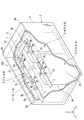
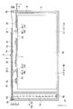
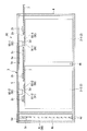
- FIG. 4 is a cross-sectional view taken along a cutting line AA in the battery pack of FIG. 3.
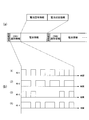
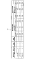
- A is a figure which shows the signal pattern of each CMU identification information
- (b) is a figure which shows the detail of a battery side information signal.
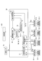
- the battery system 1 of the first embodiment includes an assembled battery 20 composed of a plurality of battery cells 2 and a BMS (Battery Management System) that is a control unit that monitors and controls the assembled battery 20. 30, a power load 101, a control device 102, and a display unit 103.
- BMS Battery Management System
- the assembled battery 20 and the BMS 30 are housed in a battery housing case 3 to be described later to form a battery pack 100.
- the battery system 1 for example, an electric vehicle is exemplified, and the electric vehicle will be described below as an example.
- the battery system 1 may be, for example, an industrial vehicle such as a forklift or a train, or a mobile body such as an airplane or a ship in which a propeller or a screw is connected to an electric motor that is a power load 101 described later.
- it may be a stationary system such as a household power storage system or a grid-connected smoothing power storage system combined with a natural energy power generation such as a windmill or sunlight. That is, the battery system 1 is a generic term for a system that is driven by using charge / discharge of power by the battery cell 2.
- the assembled battery 20 is electrically connected to a power load 101 and a BMS 30 described later, and supplies necessary power to the power load 101 under the control of the BMS 30 and the control device 102.
- the assembled battery 20 of the present embodiment is configured by four battery cells 2 (2-1, 2-2, 2-3, 2-4) for simplification of description.
- the number of battery cells 2 constituting 20 also varies depending on the specifications of the power load 101 to be charged and discharged. For example, when the battery system 1 is an electric vehicle, the number of battery cells 2 may be about one hundred.
- the battery cell 2 is, for example, a laminated lithium ion secondary battery, and a positive electrode plate and a negative electrode plate (not shown) are in a battery container (for example, a metal battery can, which will be described as a “battery can” hereinafter) through a separator. It is stored in.
- a battery container for example, a metal battery can, which will be described as a “battery can” hereinafter
- Each battery cell 2 is provided with a measuring device for detecting detection values such as a can potential and a can temperature of the battery cell 2 (details will be described later with reference to FIG. 6).
- the battery cell 2 of this embodiment is not restricted to a laminated type, A winding type lithium ion secondary battery may be sufficient, and also other secondary batteries, such as a lead acid battery, may be employ
- the BMS 30 includes a plurality of CMUs (Cell Monitoring Units) 40 as battery side control units, a battery side wireless device 34 as a battery side communication unit, a BMU (Battery Management Unit) 50 as a management side control unit, and a management side A signal processing unit 32 as a communication unit and a management-side wireless device 33 are included.
- the BMU 50 is connected to the control device 102 in the battery system 1 through a bus that transmits and receives data.
- the BMU 50 calculates related information regarding each battery cell 2 (information related to a parameter value of the battery cell 2 described later, including the SOC and the deterioration degree SOH (State of Health) of each battery cell 2).
- the calculation of the related information is not limited to the example performed by the BMU 50, and may be performed by the control device 102 described later.
- the CMU 40 is provided for each battery cell 2.
- branch numbers 1 to 4 are attached to the end of the code, corresponding to battery cells 2-1, 2-2, 2-3, 2-4, The description will be made as CMUs 40-1, 40-2, 40-3, and 40-4, and other configurations will be described with the branch numbers assigned to the reference numerals in the same manner when corresponding to each battery cell 2.
- Each CMU 40 converts a detection value input from the measurement device into a parameter value as a digital signal by an ADC (Analog Digital Converter) 31 described later.
- ADC Analog Digital Converter
- the battery-side wireless device 34 is provided corresponding to each CMU 40 on a one-to-one basis.
- the battery-side wireless device 34 includes a control unit, a wireless transmission unit, and a wireless reception unit (not shown), and a known wireless device can be applied.
- Each battery-side radio apparatus 34 is electrically connected to the corresponding CMU 40.
- the BMS 30 includes a management-side wireless device 33 that corresponds to the battery-side wireless device 34 on a one-to-one basis.
- the management-side wireless device 33 includes a control unit (not shown), a wireless transmission unit, and a wireless reception unit, and a known wireless device is applicable.
- Each management-side wireless device 33 is electrically connected to the signal processing unit 32, and performs signal processing on a battery-side wireless signal Ssc (described later) as a battery-side information signal received from the corresponding battery-side wireless device 34. It transmits to the part 32.
- the signal processing unit 32 is provided in one-to-one correspondence with the management-side wireless device 33 and includes a memory (not illustrated) (for example, a non-volatile memory or a volatile memory including a rewritable area).
- the electric power load 101 converts, for example, electric power supplied from the assembled battery 20 into motive power, and an electric motor (electric motor) is exemplified in the case of the electric vehicle shown in the present embodiment.
- the control device 102 is, for example, an ECU (Electronic Control Unit) mounted on an electric vehicle, and drives the power load 101 by being incorporated in the battery system 1 and controlling the discharge of the assembled battery 20 via the BMS 30.
- the control device 102 may control the entire electric vehicle such as a wiper or a navigation device mounted on the electric vehicle, for example.
- the display unit 103 is a device that visually outputs the related information of each battery cell 2 or the entire assembled battery 20 and battery information to be described later, such as an instrument panel provided in an electric vehicle, a car navigation monitor, and the like. Can be mentioned.
- the display unit 103 is connected to the control device 102 via a bus for receiving data. And the display part 103 displays the said relevant information etc. under control of this control apparatus 102, after the control apparatus 102 receives the input signal input by the driver
- the output of the related information or the like is not limited to this mode, and the related information or the like may be output by voice through a speaker provided in the electric vehicle, for example.
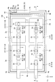
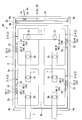
- the battery pack 100 includes a battery housing case 3 that houses a plurality of battery cells 2.
- the battery housing case 3 has a substantially rectangular case main body 4 with one surface opened, and a lid portion 5 that closes the opening of the case main body 4.
- Bolt holes 4 a are formed at the four corners of the opening edge of the case body 4.
- a bolt insertion hole 5a is formed in the lid 5 at a position corresponding to the bolt hole 4a of the case body 4, and the fixing bolt 5b is screwed into the bolt hole 4a through the bolt insertion hole 5a (tightened with a screw).
- the lid portion 5 and the case main body 4 are integrated with each other.
- the bolt holes 4a and the bolt insertion holes 5a formed at one of the four corners of the battery housing case 3 are different in the number of holes compared to the other corners.
- the case body 4 includes a battery storage unit 4b that stores a plurality of battery cells 2, and a control board storage unit 4c that stores a management-side control board 6 on which the BMU 50 is mounted.
- the battery storage portion 4b is formed in a space in which the four battery cells 2 can be stored in the storage positions arranged in 2 rows and 2 columns as described above.
- Each battery cell 2 accommodated in the battery accommodating part 4b is comprised by the substantially rectangular shape in this embodiment, and has the upper surface 2a and the side surface 2h.
- the positive electrode terminal 2b and the negative electrode terminal 2c protrude from the upper surface 2a of the battery cell 2, and are electrically connected to the above-described laminate composed of the positive electrode plate and the negative electrode plate.
- the four battery cells 2 to be arranged are connected in series so that the positive electrode terminal 2b and the negative electrode terminal 2c are connected by the bus bar 7 between adjacent battery cells.
- the bus bar 7 connected to the positive terminal 2b of the battery cell 2 at one end of the series connection and the negative terminal 2c of the battery cell 2 at the other end protrudes from the battery housing case 3 and can be externally connected. It is possible.
- the battery-side control board 2d is bonded and fixed to the upper surface 2a of each battery cell 2 in a region where it does not overlap with a safety valve (not shown).
- the above-described CMU 40 and the battery-side wireless device 34 are mounted on the battery-side control board 2d, and the CMU 40 and the battery-side wireless device 34 are electrically connected via a wiring (not shown).
- the battery side control board 2d is electrically connected to the corresponding battery cell 2, and the CMU 40 and the battery side wireless device 34 obtain power necessary for driving from the battery cell 2.
- the upper side in FIG. 3 is one row, the lower side is two rows, and the left side is A
- the column and the right side are the B columns.
- the position of the battery cell 2-1 is the battery position 1-A
- the position of the battery cell 2-2 is the battery position 1-B
- the position of the battery cell 2-3 is the battery position 2.
- the position of battery cell 2-4 is referred to as battery position 2-B.
- a pair of protrusions 4 d, 4 d are formed on the inner surface of the control board housing portion 4 c above the bottom surface of the case body 4 (in the Z direction It is arranged toward the positive side.
- the management-side control board 6 is fixed and held in the control board storage part 4c by inserting the edge part between the pair of protrusions 4d and 4d.
- the management-side control board 6 housed in the control board housing portion 4 c is connected to the bus bar 7 described above via the feeder line H, and receives power necessary for driving from the battery cell 2. Specifically, as shown in FIG.
- the contact terminal G is formed in the protruding portion of the case body 4 where the bus bar 7 protrudes outward, and the bus bar 7 is fixed to the electrode terminals 2 b and 2 c.
- power required for the BMU 50 is supplied from the battery cell 2 via the feeder line H.
- the above-described BMU 50 is mounted on the management-side control board 6, and the BMU 50 and the management-side wireless device 33 are electrically connected via a second connection terminal 6b (described later).
- the management-side wireless device 33 and the battery-side wireless device 34 are arranged to face each other so as to overlap each other when viewed in plan from the Z direction with the lid 5 attached to the case body 4.
- the communication between the battery-side wireless device 34 and the management-side wireless device 33 uses directional electromagnetic waves (for example, light oscillated by a laser diode is desirable. In the following description, light is used as an example of electromagnetic waves). It is desirable to use it. Therefore, when the battery-side radio signal Ssc is transmitted by the corresponding battery-side radio device 34, the management-side radio device 33 can receive the light as the battery-side radio signal Ssc. Note that the above-described communication may be performed using a radio wave having no directivity by providing the battery housing case 3 with a radio wave shielding member so as to avoid signal interference with other radio apparatuses.
- wireless apparatus 33 is not restricted to the example installed facing the management side radio
- the management-side control board 6 is provided with two connection terminals, a first connection terminal 6a and a second connection terminal 6b.
- the first connector 3 a to which the first connection terminal 6 a is connected and the second connection terminal 6 b are connected to the surface of the case body 4 that faces the management-side control board 6.
- the first connector 3a is connected to a connection cable 3d extending through the wall of the battery housing case 3 to the outside, whereby the control device 102 and the BMU 50 of the battery system 1 are connected to the first connector 3a.
- connection terminal 6a the connection terminal 6a, the first connector 3a, and the connection cable 3d.
- the second connector 3b and the third connector 3c are electrically connected, whereby the lid-side connection terminal 5d connected to the third connector 3c and the BMU 50 are connected to the third connector 3c and the second connector 3c. Communication is possible through the connector 3b and the second connection terminal 6b.
- a pressure sensor capacitor type pressure sensor or the like
- the pressure sensor has a function of outputting a 1-bit detection signal Sc indicated by “0” or “1” when the lid 5 is opened and closed (details will be described later with reference to FIG. 10).
- connection sensor 3e is electrically connected to the BMU 50, and obtains electric power necessary for driving from the battery cell 2 through the BMU 50.
- the opening and closing of the lid 5 is detected by the pressure sensor described above.
- a connection sensor is provided in the vicinity of the third connector 3c, and the lid-side connection terminal 5d and the third connector 3c are connected to each other.
- the detection signal Sc may be output when the connection / disconnection is performed.
- the inner surface 5c facing the battery housing portion 4b and the control board housing portion 4c has a lid-side connection terminal connected to the third connector 3c. 5d is provided.
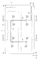
- a plurality of management-side radio devices 33 and signal processing units 32 are provided on the inner surface 5c corresponding to the battery-side control board 2d (CMU 40 and the battery-side radio device 34) of each battery cell 2.
- the management-side wireless device 33 and the corresponding signal processing unit 32 are electrically connected via a bus (not shown).
- the lid-side connection terminal 5d is provided at a position corresponding to the third connector 3c described above, and the lid-side connection terminal is connected to the third connector 3c as the case body 4 is closed. 5d is fitted and can be electrically connected to each other.
- Each signal processing unit 32 is connected in series by a printed wiring 5e formed on the inner surface 5c of the lid 5, and any one of the signal processing units 32 is electrically connected by the lid-side connection terminal 5d and the printed wiring 5e. Connected to. Thereby, transmission / reception of signals between the BMU 50 and each signal processing unit 32 becomes possible via the lid-side connection terminal 5d and the third connector 3c.
- the lid side connection terminal 5d, the battery cell 2-2 (battery position 1-B) and the corresponding signal processing unit 32-4, the battery cell 2-4 (battery position 2-B), Corresponding signal processing unit 32-3, battery cell 2-3 (battery position 2-A) and corresponding signal processing unit 32-2, and battery cell 2-1 (battery position 1-A) and corresponding signal processing unit 32 They are connected in series in the order of -1.
- Each signal processing unit 32 includes a control unit and a memory (not shown).
- the memory includes, for example, a rewritable area and a non-rewritable area, and unique address information is recorded in the non-rewritable area.
- each signal processing unit 32 Since each signal processing unit 32 is fixed to the inner surface 5c of the lid 5, and the lid 5 is always connected to the case body 4 in a fixed direction, the installation position of each signal processing unit 32 is always a specific battery position. Will correspond.
- the control unit of the signal processing unit 32 adds the address information to the battery-side radio signal Ssc sequentially transmitted from the battery-side radio device 34 to generate a combined battery-side radio signal Ssd.
- Each signal processing unit 32 generates reception signals Ab and Ac indicating that the battery side radio signal Ssc has been received.
- the reception signal Ab is sent to the management side radio signal reception unit 52, and the reception signal Ac is sent to the management side.
- the data is transmitted to the battery-side wireless device 34 via the wireless device 33 (described later with reference to FIGS. 7 and 10).
- each signal processing unit 32 is connected in series via one bus
- the BMU 50 communicates with each signal processing unit 32 based on the address information Da.
- the address information Da is, for example, 2-bit digital information, and each address information Da is associated with a battery position in advance (refer to the management information table T1 in FIG. 11 as appropriate).
- the address information Da of the management-side wireless device 33-4 is “01” corresponding to the battery location “1-B”
- the address information Da of the management-side wireless device 33-3 is the battery location. “11” is set in correspondence with “2-B”.
- the address information is 2-bit digital information, but other than 2 bits depending on the number of battery cells 2 accommodated. It may be digital information.
- FIG. 6 is a diagram showing details of the CMU 40 configuring the BMS 30.
- the CMU 40 includes an ADC 31, a connection information reception unit 41, a battery side storage unit 42, a battery state information generation unit 43, and a battery side wireless signal generation unit 44.
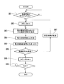
- the connection information reception unit 41 is electrically connected to the battery-side radio signal generation unit 44 via an internal bus. As shown in FIG. 7, the connection information receiving unit 41 receives connection information Dc (described later) generated by the BMU 50 when the lid 5 is incorporated in the case body 4 (step SB1).
- connection information Dc When the connection information Dc is received by the connection information receiving unit 41, the connection information receiving unit 41 transmits a signal indicating that the connection information Dc has been received to the battery-side wireless signal generation unit 44.
- the battery-side radio signal generation unit 44 is also electrically connected to the battery-side storage unit 42 and the battery state information generation unit 43 via an internal bus. After receiving the signal from the connection information receiving unit 41, the battery-side radio signal generating unit 44 sets the value of a counter N (not shown) provided in the CMU 40 to zero (“0”) (step SB2). .
- the battery-side radio signal generation unit 44 extracts the battery specific information Dp and the CMU identification information Ci stored in the battery-side storage unit 42 (step SB3), and obtains the battery state information Ds from the battery state information generation unit 43. Receive (step SB4). Then, the battery-side radio signal generation unit 44 generates the battery-side radio signal Ssc based on the battery specific information Dp, the CMU identification information Ci, and the battery state information Ds, and sends the battery-side radio signal to the battery-side radio device 34. Ssc is transmitted (step SB5). The battery-side radio device 34 transmits the received battery-side radio signal Ssc toward the management-side radio device 33.
- FIG. 8B shows an example of the battery side radio signal Ssc of the present embodiment.
- the battery-side radio signal Ssc is a digital signal in which a unit signal composed of a synchronization signal, the above-described CMU identification information Ci and battery information is repeated, and has a bit length of 16 bits as a unit signal, for example.
- the synchronization signal is configured to have a unique value of 3 bits, for example.
- the CMU identification information Ci is identification information (for example, corresponding to the serial number of the CMU 40) for specifying the CMU 40 associated with the battery cell 2, and has a bit length of 3 bits as shown in FIG. 8A, for example.
- each CMU 40 is configured with a unique signal pattern.
- the CMU identification information Ci is recorded in the battery side storage unit 42 when the CMU 40 is manufactured, for example.
- the battery information is digital data including battery specific information Dp and battery state information Ds, and has a bit length of 10 bits, for example.
- the battery specific information Dp is digital data (for example, having a bit length of 5 bits) based on the manufacturing number of the battery cell 2 to which the CMU 40 is attached, and is a value specific to each battery cell 2.
- the battery specific information Dp is preferably recorded in the battery side storage unit 42 by the operator when the battery side control board 2d including the CMU 40 is attached to the battery cell 2, for example.
- the battery state information Ds is digital data based on a detection value that is appropriately extracted from the battery cell 2, and has a bit length of, for example, 5 bits.
- a specific generation process of the battery state information Ds is as follows.
- each battery cell 2 includes a thermometer 2e capable of measuring a can temperature, a first voltmeter 2f capable of measuring a voltage between the positive terminal 2b and the negative terminal 2c, and a reference potential.
- a second voltmeter 2g capable of measuring a can battery which is a potential difference between (for example, negative electrode potential) and the can.
- the positive electrode terminal 2b of the battery cell 2 of the present embodiment is connected to the battery can via a desired resistance, whereby the can potential and the potential of the positive electrode terminal 2b are equal.
- the detection values from the thermometer 2e, the first voltmeter 2f, and the second voltmeter 2g are respectively input to the ADC 31 of the CMU 40 to be converted from an analog signal (detection value) to a digital signal (parameter value). Later, it is input to the battery state information generator 43.
- the battery state information generation unit 43 the battery state information is synthesized by combining the temperature data in the thermometer 2e, which is the parameter value, the inter-terminal voltage data in the first voltmeter 2f, and the can potential data in the second voltmeter 2g. Ds is generated, and the battery state information Ds is output to the battery-side radio signal generation unit 44.
- step SB6 the battery-side radio signal generation unit 44 has received a reception signal Ac (described later with reference to FIG. 10) generated and output by the signal processing unit 32. Determination is made (step SB6). If the reception signal Ac has not yet been received, the battery-side radio signal generation unit 44 adds “1” to the value of the counter N (step SB8), and then adds the counter “1”. It is determined whether the value of “3” is “3” (step SB9). If the counter value is not “3” in step SB9 (that is, “1” or “2”), the process returns to step SB3 and the battery-side radio signal Ssc is returned again by the battery-side radio signal generator 44. Is generated and output.
- the battery-side radio signal generation unit 44 stops generating / outputting the battery-side radio signal Ssc.
- the reception signal Ac cannot be received from the signal processing unit 32, and there is a high possibility that any of the components on the BMU 50 side including the signal processing unit 32 and the management-side wireless device 33 is defective.
- the battery-side radio signal generation unit 44 generates and outputs the battery-side radio signal Ssc three times at the maximum.
- the number of times is not particularly limited to three.
- the determination at step SB9 is performed. A numerical value other than “3” may be used.
- step SB2 When the battery-side radio signal generation unit 44 receives the reception signal Ac in the process of generating / outputting the battery-side radio signal Ssc (“Yes” in step SB6), step SB2 is triggered again after a predetermined time has passed. The subsequent processing is performed (step SB7).
- the “predetermined time” for example, 1 hour or the like is exemplified, and after the elapse of the predetermined time, the battery-side radio signal generation unit 44 generates and outputs the battery-side radio signal Ssc, so that the lid 5 becomes the case body 4. After being combined, the battery-side radio signal Ssc is periodically transmitted to the BMU 50.
- the BMU 50 includes a connection information generation unit 51, a management-side radio signal reception unit 52, a true / false determination unit 53, a management-side storage unit 54, and a battery state monitoring unit 55.
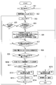
- the connection information generation unit 51 is electrically connected to the connection sensor 3e and each signal processing unit 32. As shown in FIG. 10, when receiving the detection signal Sc output from the connection sensor 3e, the connection information generation unit 51 determines whether the received detection signal Sc is “0” (step SC1).
- the detection signal Sc is a digital signal output from the connection sensor 3e when the lid 5 is opened and closed, and has a bit length of 1 bit, for example.
- the connection sensor 3e of this embodiment is a capacitive pressure sensor, and has a value of “1” when the lid 5 is removed from the case body 4 (that is, when the lid 5 is opened), for example.
- a detection signal Sc is output.
- the detection signal Sc having a value of “0” is output.
- the connection information generation unit 51 When the received detection signal Sc is “0”, the connection information generation unit 51 generates the connection information Dc and transmits the connection information Dc to each signal processing unit 32 (step SC2). Then, the BMU 50 sets a value of a built-in counter (not shown) to “0” (step SC3), and subsequently determines whether or not the reception signal Ab is received from the signal processing unit 32 (step SC4).
- the reception signal Ab is a signal indicating that the signal processing unit 32 has received the battery-side radio signal Ssc, and is generated by each signal processing unit 32 and transmitted to the management-side radio signal reception unit 52.
- the signal processing unit 32 adds address information Da to the received battery-side radio signal Ssc and holds it in a built-in memory.
- the address information Da is added to the reception signal Ab and transmitted to the management-side radio signal reception unit 52.
- the management-side radio signal receiving unit 52 receives the reception signal Ab for a predetermined time (step SC5). When the predetermined time has elapsed, the predetermined time has passed to the control device 102 via the management information generating unit 56. This is notified (step SC16).
- reception signal Ab is not received within a predetermined time, there is a high possibility that the signal processing unit 32, the management-side wireless device 33, or any constituent member on the CMU 40 side is defective, and the control device 102 uses the user. This is because it is necessary to give a warning.
- step SC5 the reception signal Ab is continuously received. If the reception signal Ab is received, the process proceeds to step SC6.
- the management-side wireless signal receiving unit 52 that has received the reception signal Ab (1) generates the above-described reception signal Ac and transmits it to the corresponding battery-side wireless device 34 to the signal processing unit 32 that has transmitted the reception signal Ab.
- a control signal and (2) a control signal for transmitting the combined battery side radio signal Ssd generated and held by the signal processing unit 32 to the management side radio signal receiving unit 52 are transmitted (step SC6). Thereafter, the management-side radio signal receiving unit 52 waits until the combined battery-side radio signal Ssd is received from the signal processing unit 32 (step SC7).
- the target battery cell is received. 2 and CMU 40 are checked for authenticity (step SC8).
- the authenticity determination of the battery cell 2 and the CMU 40 is performed as follows, for example.
- the authenticity determination unit 53 of the BMU 50 is electrically connected to the management-side radio signal reception unit 52 and the management-side storage unit 54 via an internal bus, and the combined-cell-side radio signal Ssd from the management-side radio signal reception unit 52.
- the battery specific information Dp and the CMU identification information Ci included in the data are received, and the inquiry data stored in the management-side storage unit 54 is extracted.
- the authenticity determination unit 53 determines whether or not the target battery cell 2 and the CMU 40 are authentic (normal) by comparing the inquiry data with the battery specific information Dp and the CMU identification information Ci. To do.
- the “inquiry data” is data used to determine whether the battery cell 2 and the CMU 40 are authentic.
- the serial numbers of the battery cell 2 and the CMU 40 can be used. Therefore, in the present embodiment, for example, the beginning or the end of the manufacturing number used for the battery cell 2 or the CMU 40 is a common symbol, number, or their code indicating that it is a genuine product (this is referred to as “genuine product data”).
- the inquiry data is formed based on the genuine product data.
- the battery cell 2 and the CMU 40 that are newly manufactured as genuine products have common genuine product data, so that it is possible to save the trouble of updating the inquiry data stored in the management-side storage unit 54 one by one.
- the “genuine product” in this embodiment is a battery cell or CMU that is not a so-called counterfeit product, and is similar to other battery cells or CMU types / specifications, so there is no risk of performance degradation.
- a battery cell or CMU may be included.
- the management information generation unit 56 includes the battery specific information including the authenticity result. Dp and address information Da are notified.
- the management information generation unit 56 that has received the true / false result from the true / false determination unit 53 reads the management information table T1 stored in the management-side storage unit 54, and authenticates the column corresponding to the address information Da. A false result is input and updated (step SC15). As shown in FIG.
- the management information table T1 includes a battery position column, a battery cell determination result column indicating the authenticity determination result of the battery cell 2, a CMU determination result column indicating the authenticity determination result of the CMU 40, and the state of the battery cell 2.
- a state determination result column indicating the determination result and a battery state information column into which the battery state information Ds is input are configured. Among these, in the determination result column, “1” is input if it is authentic / normal based on the determination result, and “0” is input if it is not authentic / abnormal.
- Each parameter value (can temperature, voltage between terminals, can potential, etc.) included in the battery state information Ds is input to the battery state information column.
- the management information table T1 may further include a battery specific information column in which the battery specific information Dp is input. In this case, for example, the serial number included in the battery specific information Dp is input in the battery specific information column.
- the management information generation unit 56 notifies the control device 102 of a notification signal indicating that the battery cell 2 or CMU 40 that is not authentic is incorporated in the battery system 1 (step SC16).
- the control device 102 of the battery system 1 that has received the notification signal does not operate the power load 101 and displays on the display unit 103 that the battery cell 2 or the CMU 40 is not genuine.
- the user is notified of the necessity of replacing the battery cell 2 or the CMU 40.
- the power load 101 does not necessarily have to be operated. For example, an output (50% of the rating) for operating only the minimum necessary functions for ensuring safety.
- the operation of the power load 101 may be stopped after a certain period of time has elapsed. Further, the output indicating that the battery cell 2 or the CMU 40 is not a genuine product may be output by voice notification instead of or in addition to the display by the display unit 103.
- step SC9 when it is determined in step SC9 that the battery cell 2 and the CMU 40 to be determined are authentic (normal), the authenticity determination unit 53 associates the battery cell 2 with the battery unique information Dp and the CMU identification information Ci, and 2 and a signal indicating that the CMU 40 is authentic (normal) are transmitted to the management information generation unit 56. Then, the management information generation unit 56 that has received these pieces of information transmits an instruction to the battery state monitoring unit 55 to monitor the battery state. Monitoring of the battery state in the battery system 1 of the present embodiment is performed as follows. That is, the battery state monitoring unit 55 is electrically connected to the management-side radio signal receiving unit 52, the management-side storage unit 54, and the management information generating unit 56 via an internal bus.
- the allowable parameter value information table T2 includes a parameter value column indicating the type of each parameter value, a range determined to be normal as the battery cell 2 as the parameter value, corresponding to each parameter value, and And a permissible parameter value field for displaying a permissible parameter value that is a threshold value of a range determined to be abnormal.
- one threshold value (Tbc, Vtc, and Vbc) is illustrated as an allowable parameter value for simplification of description, but a predetermined range having an upper limit and a lower limit without necessarily being one threshold value. It is good.
- the battery state monitoring unit 55 determines whether each parameter value of the corresponding battery cell 2 is normal or abnormal based on the received battery state information Ds and the allowable parameter value information table T2 (step SC11). More specifically, the battery state monitoring unit 55 refers to the allowable parameter value information table T2 stored in the management-side storage unit 54, and compares each parameter value constituting the battery state information Ds with the allowable parameter value. I do. Then, the battery state monitoring unit 55 determines that the parameter value included in the battery state information Ds is normal if the parameter value is less than or equal to the allowable parameter value, and abnormal if the parameter value exceeds the allowable parameter value.
- the battery state monitoring unit 55 includes information indicating the abnormality determination, the address information Da corresponding to the battery cell 2 determined to be abnormal, and the battery state. These pieces of information are transmitted to the management information generation unit 56 in association with the information Ds.
- the management information generation unit 56 that has received the information indicating the abnormality determination and the address information Da and the battery state information Ds corresponding to the battery cell 2 determined to be abnormal reads the management information table T1 described above from the management-side storage unit 54.
- the management information table T1 is updated (step SC15), and the determination result indicating the abnormality determination, the position of the battery cell 2, the battery state, and the like are notified to the control device 102 (step SC16).
- the control device 102 that has received the determination result indicating the abnormality determination and the position and battery state of the battery cell 2 controls the display unit 103 to display the position and battery state of the battery cell 2 indicating abnormality. I do. In this case, the control device 102 performs control for limiting the output of the power load 101 (for example, 50% output) in addition to performing control for displaying the position and battery state of the battery cell 2 indicating abnormality, You may control to stop operation
- the position of the battery cell 2 indicating abnormality is not limited to the example displayed on the display unit 103, and may be notified by voice through a speaker or the like.
- the battery state monitoring unit 55 determines that the parameter value of the battery cell 2 is normal in step SC11, the information indicating the normal determination, the address information Da corresponding to the battery cell 2 determined to be normal, and the battery state These pieces of information are transmitted to the management information generation unit 56 in association with the information Ds.
- the management information generation unit 56 that has received the information indicating the normality determined in step SC9 and step SC11, the address information Da corresponding to the battery cell 2 determined to be normal, and the battery state information Ds is the management information table described above.
- T1 is read from the management-side storage unit 54 and the management information table T1 is updated (step SC12). Specifically, as shown in FIG.
- the management information generation unit 56 is genuine or normal for the battery cell determination result column, the CMU determination result column, and the state determination result column for the corresponding battery position (address information Da). “1” is input as a value indicating that. Further, the management information generation unit 56 inputs each parameter value (can temperature, terminal can voltage, can potential) based on the battery state information Ds for the battery state information column of the corresponding battery position (address information Da). Then, after updating the management information table T1, the management information generation unit 56 adds “1” to the value of the counter M (step SC13).
- the management information generation unit 56 determines whether the value of the counter M is “4” (step SC14). If the value of the counter M is not “4”, the management information generation unit 56 returns to step SC4 again to perform other signal processing. The reception signal Ab from the unit 32 is received. As described above, in this embodiment, since the four battery cells 2 are accommodated in the battery accommodating case 3, it is determined in step SC14 whether the value of the counter M is “4”. That is, the numerical value determined in step SC14 corresponds to the number of battery cells 2 housed in the battery housing case 3, and this numerical value is appropriately changed according to the number of battery cells 2 housed.
- step SC14 When the value of the counter M is “4” in step SC14, that is, when each value of the management information table T1 is updated for all the battery cells 2 accommodated in the battery accommodating case 3, the process returns to step SC3. Then, the value of the counter M is set to zero (“0”), and the processes after step SC4 are repeated.
- the address information Da is added to the battery-side radio signal Ssc by the management-side communication unit (the signal processing unit 32 and the management-side radio device 33) whose arrangement position is specified in advance. Then, the transmission is made to the BMU 50. Thereby, the battery-side radio signal Ssc transmitted from each battery-side communication unit (battery-side radio device 34) to the BMU 50 is transmitted from the CMU 40 corresponding to the battery cell 2 arranged at which position. Can be identified.
- the battery cells 2 are simply stored in the battery storage case 3 in a predetermined arrangement, and the BMU 50, the CMU 40, the battery-side wireless device 34, and the management-side wireless device 33 are activated, without bothering the operator.
- the positions of the battery cell 2 and the CMU 40 can be associated with the information of the battery cell 2 and the CMU 40. Therefore, it is possible to appropriately manage these while specifying the positions of the battery cell 2 and the CMU 40 in the battery housing case 3 while minimizing the burden on the operator.
- the battery information of the battery cell 2 is a wireless system using electromagnetic waves for communication between the CMU 40 side and the BMU 50 side. For this reason, when installing the battery cell 2 in the battery accommodation case 3, the effort which connects the wiring for communication between CMU40 and BMU50 can be saved.
- identification information battery specific information Dp and CMU identification information Ci
- Dp and CMU identification information Ci battery specific information unique to the battery cell 2 and the CMU 40
- the BMU 50 the authenticity of the battery cell 2 and the CMU 40 can be determined, and when the forged battery cell 2 or the CMU 40 is mounted, the fact is notified to the user or the operation of the battery system 1 is performed. Can be limited. Thereby, the battery system 1 with further improved safety can be realized.
- the CMU 40 and the battery-side wireless device 34 are mounted on the battery-side control board 2d provided on the upper surface 2a of the battery cell 2.
- the present invention is not limited to this.
- 13 and 14 show a battery cell 70 in the battery system according to the second embodiment of the present embodiment.
- the second embodiment is different from the first embodiment in that each battery cell 70 is provided with a cap 72, and the battery-side control board 2d formed on the upper surface 71d of the battery cell 70.
- the connector 73 connected to the cap 72 is provided, the connector 74 connected to the connector 73, and the battery-side wireless device 34 are provided on the cap 72.
- the remaining configuration is the first configuration. This is the same as the embodiment.
- the battery cell 70 includes a battery case 71a, a positive electrode terminal 71b and a negative electrode terminal 71c provided in the battery case 71a, and a laminated body (non-condensed) composed of an electrode plate disposed inside the battery case 71a. And a cap 72 detachably attached to the battery main body 71.
- the cap 72 is formed of a resin, for example, and has a substantially rectangular shape in accordance with the outer shape of the upper surface 71d of the battery cell 70.
- the cap 72 is fitted to the battery main body 71 so as to cover the upper surface 71 d provided with the positive electrode terminal 71 b and the negative electrode terminal 71 c in the battery case 71 a of the battery main body 71.
- the cap 72 through holes 72a and 72b are formed at positions corresponding to the positive electrode terminal 71b and the negative electrode terminal 71c.
- the positive electrode terminal 2 b and the negative electrode terminal 2 c in the battery cell 70 protrude from the through holes 72 a and 72 b so that the bus bar 7 can be connected.
- the CMU 40 is provided in a region that does not overlap the safety valve (not shown) on the upper surface 71 d of the battery main body 71, and the battery-side wireless device 34 is provided on the upper surface 72 c of the cap 72.
- Connectors 73 and 74 are respectively provided on the upper surface 71d of the battery body 71 and the lower surface of the cap 72 (the surface of the cap 72 that faces the upper surface 71d of the battery cell 70).
- the connector 73 is electrically connected to the CMU 40 via wiring not shown.
- the connector 74 is electrically connected to the battery-side wireless device 34 via a wiring (not shown) formed in the cap 72.
- the connector 73 and the connector 74 can be electrically connected to each other by fitting and attaching the cap 72 to the battery main body 71.
- the CMU 40 on the battery main body 71 side and the battery-side wireless device 34 on the cap 72 side can communicate with each other through the connectors 73 and 74.
- the battery-side wireless device 34 can receive power from the battery body 71 side.
- the CMU 40 having the battery cell-specific information such as the serial number is provided on the battery body 71 side, while the versatile battery-side radio device 34 applicable to any battery cell 70 is provided.
- a cap 72 is provided. For this reason, even if the battery cell 70 deteriorates or the CMU 40 fails and needs to be replaced, the battery cell 70 and the CMU 40 are replaced, and the cap 72 and the battery-side wireless device 34 are reused. And increase in cost associated with replacement of the battery cell can be suppressed.
- FIG. 15 shows a battery pack 80 included in the battery system 1 of the third embodiment.
- the third embodiment is different from the first embodiment in that the battery side control board 2d installed in the battery cell 2 is provided on the side surface 2h of the battery cell 2, and the battery side control board.
- the signal processing unit 32 and the management-side wireless device 33 corresponding to 2d are provided at positions facing the side surface 2h of the battery cell 2 on the case body 4 side, and the rest of the configuration is the same as in the first embodiment. is there.
- the management-side wireless device 33 is arranged on the inner side surface (the surface facing the battery cell 2) of the case body 4 in the battery housing case 3.
- the battery side control board 2d (including the battery side wireless device 34) provided on the battery cell 2 side is made publicly known such as an adhesive on the side surface 2h of the battery cell 2 in correspondence with the management side wireless device 33. It is fixed by the fixing means.
- the signal processing unit 32 and the management-side wireless device 33 are provided on the case body 4 side in which the management-side control board 6 on which the BMU 50 is mounted is accommodated.
- the connection structure for enabling communication between the management-side wireless device 33 and the BMU 50 side can be simplified.
- the connection structure between the third connector 3c and the lid-side connection terminal 5d in the first embodiment can be omitted.
- the battery pack 80 can be configured without the lid 5 and the battery housing
- the battery system 1 excellent in maintainability can be realized while the upper surface of the case 3 remains open.
- FIG. 16 shows a fourth embodiment of the present invention.
- the battery system 1 does not include the battery-side wireless device 34, the signal processing unit 32, and the management-side wireless device 33, and the CMU 95 and the BMU 96 are based on connectors. This is because communication is performed, and the remaining configuration is the same as that of the first embodiment.
- the battery pack 90 includes a battery-side connector 91 as a battery-side communication unit provided on the battery-side control board 2 d of each battery cell 2, and a lid portion of the battery housing case 3.
- each battery side connector 91 is electrically connected to the corresponding CMU 95 on the battery side control board 2d.
- Each case side connector 92 (92-1, 92-2, 92-3, 92-4) is connected in series by a printed wiring 5e, and each case side connector 92 receives the address information Da described above. It is a control connector with a memory function that can be held and added.
- each case-side connector 92 is configured to be able to hold the address information Da, the same effects as those of the first embodiment can be obtained. Furthermore, according to the present embodiment, the communication between the CMU 95 and the BMU 96 is performed using a connector without using a wireless device, so that a battery system can be realized with a simpler configuration.
- the battery-side radio signal Ssc is generated by using the connection sensor 3e to detect that the lid 5 is attached to and detached from the case body 4.
- the control device 102 The generation of the battery-side radio signal Ssc may be started at a predetermined timing by the above control.
- the battery-side radio signal Ssc includes the CMU identification information and the battery information.
- the battery-side radio signal Ssc only needs to include at least the battery state information Ds.
- the battery side information signal Ssc may be composed of battery state information Ds and at least one of CMU identification information Ci and battery specific information Dp.
- the management information table T1 is generated based on information included in the battery side information signal Ssc.
- the present invention provides a battery-side control that is provided corresponding to a plurality of battery cells and that is electrically connected to the battery cells and generates a battery-side information signal including battery information of the battery cells.
- a battery housing case that houses a plurality of the battery cells, accommodates at least the battery side control unit, and is provided corresponding to the battery side control unit and transmits the battery side information signal
- a synthetic battery side information signal is generated by adding address information to the battery side information signal received from the battery side communication part, provided in the battery housing case corresponding to the communication part and the battery side communication part.
- a management-side communication unit that is electrically connected to the management-side communication unit, and the battery information and the address information included in the composite battery-side information signal received from the management-side communication unit Based on relates to a battery system having a management-side control unit that generates management information corresponding to each of said battery cells inside the battery housing case. According to the present invention, it is possible to easily install and replace the battery cell while making it possible to manage the battery cell while minimizing the burden on the operator.
- Battery system 2 Secondary battery (battery cell) 3 Battery housing case 32 Signal processing unit (management communication unit) 33 Management side wireless device (Management side communication unit) 34 Battery side wireless device (Battery side communication part) 40, 95 CMU (battery side control unit) 41 connection information reception unit 42 battery side storage unit 43 battery state information generation unit 44 battery side radio signal generation unit 50, 96 BMU (management side control unit) REFERENCE SIGNS LIST 51 connection information generation unit 52 management side wireless signal reception unit 53 authenticity determination unit 54 management side storage unit 55 battery state monitoring unit 56 management information generation unit 71 battery main body 72 cap 87 module 91 battery side connector (battery information transmission unit) 92 Case side connector (battery information receiver) 80, 90, 100 Battery pack 102 Control device 103 Display unit
Landscapes
- Engineering & Computer Science (AREA)
- Power Engineering (AREA)
- Manufacturing & Machinery (AREA)
- Chemical & Material Sciences (AREA)
- Chemical Kinetics & Catalysis (AREA)
- Electrochemistry (AREA)
- General Chemical & Material Sciences (AREA)
- Charge And Discharge Circuits For Batteries Or The Like (AREA)
- Secondary Cells (AREA)
- Battery Mounting, Suspending (AREA)
- Tests Of Electric Status Of Batteries (AREA)
Abstract
Description
本願は、2010年10月14日に日本に出願された特願2010-231639号について優先権を主張し、その内容をここに援用する。
仮に結線作業を効率化できたとしても、結線時に誤った配線が作業者によって為されてしまう可能性は否定できない。このような誤配線は電池システムにとって致命的であり、これにより電池システムが所望の動作を行うことができなくなってしまう。
このため、複数の電池セルを所定配列で電池収容ケースに収納して、管理側制御部、電池側制御部、管理側通信部、及び電池側通信部を起動させるだけで、作業者の手を煩わせることなく、管理側制御部において、上記アドレス情報に対応させて各電池セルに対応する管理情報を生成することができる。
本発明の第1の実施形態を図1から図12に基づいて説明する。以下では、図1に基づいて電池システム1の全体構成を示し、図2~5に基づいて電池システム1に含まれる電池パックの構造的な特徴を説明し、図6~12に基づいて電池システム1の電気的な構成およびその処理フローを説明する。
図1に示すように、第1の実施形態の電池システム1は、複数の電池セル2から構成された組電池20と、組電池20を監視、制御する制御部であるBMS(Battery Management System)30と、電力負荷101と、制御装置102と、表示部103とを有する。このうち組電池20とBMS30は、後述する電池収容ケース3に収容されて電池パック100となる。
電池セル2は、例えば積層型リチウムイオン二次電池であり、図示しない正極板および負極板がセパレータを介して電池容器(例えば金属製の電池缶であり、以下「電池缶」として説明する)内に収納されている。また、各電池セル2には、電池セル2の缶電位や缶温度等の検出値を検出するため計測機器が設けられている(詳細は図6を用いて後述する)。なお、本実施形態の電池セル2は積層型に限られず、捲回型リチウムイオン二次電池であってもよく、さらには鉛蓄電池等の他の二次電池を採用してもよい。
BMU50は、データを送受信するバスを介して、本電池システム1における制御装置102と接続されている。BMU50は、各電池セル2に関する関連情報(後述する電池セル2のパラメータ値に関連した情報であり、各電池セル2の上記SOCや劣化度SOH(State of Health)を含む)の演算を行う。なお、関連情報の演算は、BMU50で行う例に限られず、後述する制御装置102で行ってもよい。
図1に示すように、CMU40は、電池セル2毎に設けられている。以下においては、個別のCMU40について説明する場合には、電池セル2-1、2-2、2-3、2-4と対応させて、符号末尾に1~4の枝番を付して、CMU40-1、40-2、40-3、40-4として説明し、他の構成についても各電池セル2と対応する場合には同様に符号に枝番を付して説明を行う。
各CMU40は、上記計測機器から入力される検出値を、後述するADC(Analog Digital Converter)31によってデジタル信号としてのパラメータ値に変換する。このうち組電池20を流れる電流値は、電流計21によって検出された後にCMU40-4に内蔵されたADCに入力されるが、この態様に限定されずに他のCMU40(CMU40-1~40-3)のいずれかに入力させる構成としてもよい。
本実施形態の電池システム1では、それぞれのCMU40と1対1に対応して電池側無線装置34が設けられている。電池側無線装置34は、図示略の制御部、無線送信部、および無線受信部から構成されており、公知の無線装置が適用可能である。それぞれの電池側無線装置34は、対応するCMU40と電気的に接続されている。
信号処理部32は、管理側無線装置33と一対一で対応して設けられ、それぞれ図示略のメモリ(例えば書き換え可能な領域を含む不揮発性メモリや揮発性メモリ)を備えてなる。
制御装置102は、例えば電気自動車に搭載されるECU(Electronic Control Unit)であり、電池システム1に組み込まれてBMS30を介して組電池20の放電を制御することにより電力負荷101を駆動させる。制御装置102は、電力負荷101の駆動制御の他に、例えば電気自動車に搭載されるワイパーやナビゲーション等の車載機器など電気自動車全体の制御を行ってもよい。
表示部103は、各電池セル2または組電池20全体の上記関連情報や後述する電池情報などを視覚的に出力する装置であり、電気自動車に設けられた計器パネルやカーナビゲーション用のモニタ等が挙げられる。この表示部103は、データを受信するためのバスを介して制御装置102と接続されている。そして、表示部103は、図示しない入力装置から電気自動車の運転者などによって入力された入力信号を制御装置102が受けた後、この制御装置102の制御の下で上記関連情報等の表示を行う。なお、関連情報等の出力はこの態様に限られず、例えば電気自動車に設けられたスピーカを介して音声によって上記関連情報等の出力を行ってもよい。
図2、3に示すように、電池パック100は、複数の電池セル2を収容する電池収容ケース3を備えている。電池収容ケース3は、一面が開口した略方形状のケース本体4と、ケース本体4の開口を閉塞する蓋部5とを有する。ケース本体4の開口縁部の四隅にはそれぞれボルト孔4aが形成されている。一方、蓋部5には、ケース本体4のボルト孔4aに対応する位置にボルト挿通孔5aが形成されていて、固定用ボルト5bがボルト挿通孔5aを通してボルト孔4aに螺合(ネジにより締め合わせていること)されていることで、蓋部5とケース本体4とは一体となる。なお、本実施形態では、電池収容ケース3の四隅のうちの1つに形成されるボルト孔4aおよびボルト挿通孔5aは、他の隅に比して孔の数が異なっている。これにより、蓋部5を常に一定の向きにてケース本体4と組み合わせることができ、蓋部5とケース本体4との組み立てを誤りなく行えることができる。
電池収納部4bに収容される各電池セル2は、本実施形態では略直方形状となるよう構成され、上面2aおよび側面2hを有してなる。このうち、電池セル2の上面2aには正極端子2b及び負極端子2cが突出しており、上述した正極板及び負極板からなる積層体と電気的に接続されている。配列する四つの電池セル2は、隣り合う電池セル同士で正極端子2bと負極端子2cとがバスバー7によって接続されるようにして、直列接続されている。そして、直列接続の一端側の電池セル2の正極端子2bと、他端側の電池セル2の負極端子2cとにそれぞれ連結されたバスバー7は、電池収容ケース3から突出し、外部接続することが可能となっている。
各電池セル2の上面2aには、それぞれ電池側制御基板2dが安全弁(図示略)と重ならない領域において接着固定されている。
電池側制御基板2dには、上述のCMU40および電池側無線装置34が搭載されており、これらCMU40と電池側無線装置34は図示略の配線を介して電気的に接続されている。また、電池側制御基板2dは、対応する電池セル2と電気的に接続されており、CMU40および電池側無線装置34は、この電池セル2から駆動に必要な電力を得ている。
以下においては、四つの配列する電池セル2の電池収納部4b内における電池位置(収納位置)を特定するために、図3における上側を1行、下側を2行とし、また、左側をA列、右側をB列とする。これにより、各電池セル2の位置について、電池セル2-1の位置を電池位置1-A、電池セル2-2の位置を電池位置1-B、電池セル2-3の位置を電池位置2-A、電池セル2-4の位置を電池位置2-Bと称するものとする。
制御基板収納部4cに収納される管理側制御基板6は、給電線Hを介して上述したバスバー7と接続されており、駆動に必要な電力を電池セル2から受けている。具体的には、図4に示すとおり、ケース本体4のうちバスバー7が外部に向けて突出する突出口に接触端子Gを形成しておき、バスバー7が電極端子2b、2cに固定された際に、給電線Hを介してBMU50に必要な電力が電池セル2から供給されるようにする。
管理側制御基板6には、上述のBMU50が搭載され、BMU50と管理側無線装置33とは第二の接続端子6b(後述)を介して電気的に接続されている。管理側無線装置33と電池側無線装置34は、蓋部5をケース本体4に取り付けた状態でZ方向から平面視した場合に、互いに重なるように対向して配置されている。この電池側無線装置34と管理側無線装置33との通信は、指向性を有する電磁波(例えばレーザーダイオードにより発振される光が望ましく、以下の説明においては電磁波の一種として光を例にする)を用いて行うことが望ましい。このため、対応する電池側無線装置34によって電池側無線信号Sscが送信された場合に、当該電池側無線信号Sscとしての光を管理側無線装置33で受信することが可能となっている。なお、他の無線装置との信号干渉を避けるように電波遮蔽部材を電池収容ケース3に設けることにより、指向性を有さない電波を用いて上記した通信を行ってもよい。また、電池側無線装置34との通信が可能な限り、管理側無線装置33は蓋部5の内面5cに管理側無線装置33と対面して設置される例に限られない。すなわち、本実施形態で示す「対向」とは、「対面」を含んでおり、さらには、管理側無線装置33が電池位置と対応して、電池側無線装置34と管理側無線装置33とが通信可能にそれぞれ配置される形態をいう。
第一のコネクタ3aは、電池収容ケース3の壁体を貫通して外部へ引き延ばされた接続ケーブル3dに接続されていて、これにより電池システム1の制御装置102とBMU50とを第一の接続端子6a、第一のコネクタ3a及び接続ケーブル3dを介して通信可能としている。第二のコネクタ3bと第三のコネクタ3cとは電気的に接続されており、これにより第三のコネクタ3cに接続される蓋側接続端子5dとBMU50とを、第三のコネクタ3c、第二のコネクタ3b及び第二の接続端子6bを介して通信可能としている。
また、図4に示すとおり、ケース本体4のうち蓋部5と対向する面には、圧力センサ(静電容量型圧力センサ等)が設けられている。この圧力センサは蓋部5の開閉に伴って「0」又は「1」で示される1ビットの検出信号Scを出力する機能を備えている(詳細は図10を用いて後述する)。この接続センサ3eは、BMU50と電気的に接続されており、このBMU50を介して電池セル2から駆動に必要な電力を得ている。
なお、本実施形態では上述した圧力センサにより蓋部5の開閉を検出したが、これに換えて第三のコネクタ3c近傍に接続センサを設け、蓋側接続端子5dと第三のコネクタ3cとが接続・解除された場合に上記検出信号Scを出力する態様としてもよい。
蓋側接続端子5dは、上記した第三のコネクタ3cと対応する位置に設けられており、ケース本体4に対して蓋部5を閉塞させるのに伴って第三のコネクタ3cに蓋側接続端子5dが嵌合し、互いに電気的に接続可能となっている。
より具体的に本実施形態では、蓋側接続端子5d、電池セル2-2(電池位置1-B)と対応する信号処理部32-4、電池セル2-4(電池位置2-B)と対応する信号処理部32-3、電池セル2-3(電池位置2-A)と対応する信号処理部32-2、電池セル2-1(電池位置1-A)と対応する信号処理部32-1の順で直列接続されている。
各信号処理部32は、図示略の制御部およびメモリを備えている。このメモリは、例えば書換可能な領域と書換不可能な領域とを備えており、このうち書換不可能な領域には固有のアドレス情報が記録されている。各信号処理部32は蓋部5の内面5cに固定され、さらには蓋部5は常に一定の向きでケース本体4と接続されるため、各信号処理部32の設置位置は常に特定の電池位置と対応することになる。
そして、信号処理部32の上記制御部は、電池側無線装置34から逐次送信されてくる電池側無線信号Sscに対して上記アドレス情報を付加して合成電池側無線信号Ssdを生成する。また、各信号処理部32は、電池側無線信号Sscを受領したことを示す受領信号AbおよびAcを生成し、受領信号Abについては管理側無線信号受付部52へ、受領信号Acについては管理側無線装置33を介して電池側無線装置34へそれぞれ送信する(それぞれ図7、10を用いて後述する)。なお、本実施形態では1つのバスを介して各信号処理部32が直列に接続されているため、BMU50は、当該アドレス情報Daに基づいて各信号処理部32との通信を行う。
アドレス情報Daは例えば2ビットのデジタル情報であり、それぞれのアドレス情報Daは電池位置と予め対応付けられている(図11の管理情報テーブルT1を適宜参照されたい)。例えば図5に示す例では、管理側無線装置33-4のアドレス情報Daは電池位置「1-B」に対応させて「01」が、管理側無線装置33-3のアドレス情報Daは電池位置「2-B」に対応させて「11」が設定されている。
本実施形態では電池収容ケース3に収容される電池セル2の数は4つであるため、アドレス情報を2ビットのデジタル情報としたが、収容される電池セル2の数に応じて2ビット以外のデジタル情報としてもよい。
図6は、BMS30を構成するCMU40の詳細を示す図である。CMU40は、ADC31と、接続情報受付部41と、電池側記憶部42と、電池状態情報生成部43と、電池側無線信号生成部44とを含んで構成されている。
接続情報受付部41は、電池側無線信号生成部44と内部バスを介して電気的に接続されている。この接続情報受付部41は、図7に示すとおり、蓋部5がケース本体4に組み込まれた際にBMU50にて生成される接続情報Dc(後述する)を受け付けている(ステップSB1)。そして、接続情報Dcが接続情報受付部41に受け付けられた際、接続情報受付部41は、接続情報Dcを受け付けた旨を示す信号を電池側無線信号生成部44へ送信する。
電池側無線信号生成部44は、電池側記憶部42および電池状態情報生成部43とも内部バスを介して電気的に接続されている。この電池側無線信号生成部44は、接続情報受付部41からの上記信号を受けた後に、CMU40に備えられた図示略のカウンタNの値をゼロ(「0」)に設定する(ステップSB2)。
続いて電池側無線信号生成部44は、電池側記憶部42に記憶された電池固有情報DpとCMU識別情報Ciを抽出する(ステップSB3)とともに、電池状態情報生成部43から電池状態情報Dsを受信する(ステップSB4)。
そして、電池側無線信号生成部44は、電池固有情報Dp、CMU識別情報Ciおよび電池状態情報Dsに基づいて、電池側無線信号Sscを生成するとともに、電池側無線装置34に当該電池側無線信号Sscを送信する(ステップSB5)。電池側無線装置34では、受信した電池側無線信号Sscを管理側無線装置33に向けて送信する。
電池側無線信号Sscは、同期信号、上記したCMU識別情報Ciおよび電池情報からなる単位信号が繰り返されたデジタル信号であり、例えば単位信号として16ビットのビット長を有する。このうち、同期信号は、例えば3ビットの固有値を有して構成されている。
CMU識別情報Ciは、電池セル2と対応付けられたCMU40を特定するための識別情報(例えばCMU40の製造番号に対応)であり、例えば図8(a)に示すとおり3ビットのビット長を有してCMU40毎に異なった固有の信号パターンにて構成されている。このCMU識別情報Ciは、例えばCMU40が製造された際に電池側記憶部42に記録される。
一方、電池情報は、電池固有情報Dpと電池状態情報Dsとを含むデジタルデータであり、例えば10ビットのビット長を有してなる。このうち電池固有情報Dpは、CMU40が取り付けられた電池セル2の製造番号に基づくデジタルデータ(例えば5ビットのビット長を有する)であり、各電池セル2に固有の値となっている。この電池固有情報Dpは、例えばCMU40を含む電池側制御基板2dが電池セル2に取り付けられる際に、作業者により電池側記憶部42に記録されることが望ましい。
また、電池状態情報Dsは、電池セル2から適宜抽出される検出値に基づくデジタルデータであり、例えば5ビットのビット長を有している。具体的な電池状態情報Dsの生成過程は次のとおりである。
温度計2e、第一の電圧計2f及び第二の電圧計2gからの検出値は、CMU40のADC31にそれぞれ入力されることでアナログ信号(検出値)からデジタル信号(パラメータ値)に変換された後に、電池状態情報生成部43に入力される。
電池状態情報生成部43では、パラメータ値である温度計2eにおける温度データ、第一の電圧計2fにおける端子間電圧データと、第二の電圧計2gにおける缶電位データとを合成して電池状態情報Dsを生成し、この電池状態情報Dsを電池側無線信号生成部44に出力する。
そして、ステップSB9にてカウンタの値が「3」でない場合(すなわち、「1」あるいは「2」のとき)には、ステップSB3に戻って電池側無線信号生成部44により再度電池側無線信号Sscが生成・出力される。
一方、ステップSB9でカウンタの値が「3」の場合には、電池側無線信号生成部44は電池側無線信号Sscの生成・出力を中止する。この場合は、信号処理部32から上記受領信号Acが受信できておらず、信号処理部32や管理側無線装置33を含むBMU50側の構成部材のいずれかに不具合が生じている可能性が高いからである。
なお、本実施形態では、電池側無線信号生成部44は電池側無線信号Sscを最大で3回生成して出力するが、その回数はとくに3回に限定されず、例えばステップSB9での判断を「3」以外の数値としてもよい。
電池側無線信号生成部44が電池側無線信号Sscを生成・出力する過程で受領信号Acを受信した場合(ステップSB6で「Yes」)には、所定時間が経過したことをトリガーとして再びステップSB2以降の処理を行う(ステップSB7)。「所定時間」としては例えば1時間などが例示され、この所定時間の経過を待って電池側無線信号生成部44が電池側無線信号Sscを生成・出力することにより、蓋部5がケース本体4に組み合わされた後に電池側無線信号SscがBMU50へ定期的に送信される。
図9に示すように、BMU50は、接続情報生成部51、管理側無線信号受付部52、真偽判定部53、管理側記憶部54、および電池状態監視部55を含んで構成されている。
接続情報生成部51は、接続センサ3eおよび各信号処理部32と電気的に接続されている。この接続情報生成部51は、図10に示すとおり、接続センサ3eから出力される検出信号Scを受信すると、受信した検出信号Scが「0」であるかを判定する(ステップSC1)。上記したとおり、この検出信号Scは、蓋部5の開閉に伴って接続センサ3eから出力されるデジタル信号であり、例えば1ビットのビット長を有している。本実施形態の接続センサ3eは静電容量型圧力センサであり、例えば蓋部5がケース本体4から外れた際(すなわち蓋部5が開けられた場合)には、「1」の値を有する検出信号Scが出力される。一方、蓋部5がケース本体4に組み込まれた際(すなわち蓋部5が閉められた場合)には、「0」の値を有する検出信号Scが出力される。
そして、BMU50は、内蔵する図示略のカウンタMの値を「0」に設定し(ステップSC3)、続けて受領信号Abを信号処理部32から受信したか判定する(ステップSC4)。ここで、受領信号Abは、信号処理部32が電池側無線信号Sscを受信したことを示す信号であり、各信号処理部32によって生成されて管理側無線信号受付部52に送信される。具体的には、電池側無線信号Sscが信号処理部32によって受信された際に、信号処理部32は、受信した電池側無線信号Sscにアドレス情報Daを付加して内蔵したメモリに保持するとともに、受領信号Abに自己のアドレス情報Daを付加して管理側無線信号受付部52に送信する。
管理側無線信号受付部52は、受領信号Abの受信を所定時間だけ受け付け(ステップSC5)、所定時間が経過した場合には管理情報生成部56を経由して制御装置102へ所定時間が経過したことを示す通知を行う(ステップSC16)。受領信号Abが所定時間内に受け付けられない場合、信号処理部32や管理側無線装置33、あるいはCMU40側のいずれかの構成部材に不具合が生じている可能性が高く、制御装置102により使用者等へ警告を行う必要があるからである。
受領信号Abを受信した管理側無線信号受付部52は、受領信号Abを送信した信号処理部32に対し、(1)上述した受領信号Acを生成して対応する電池側無線装置34へ送信する制御信号と、(2)信号処理部32で生成・保持された合成電池側無線信号Ssdを管理側無線信号受付部52へ送信する制御信号、を送信する(ステップSC6)。
その後、管理側無線信号受付部52は、合成電池側無線信号Ssdを信号処理部32から受信するまで待機し(ステップSC7)、合成電池側無線信号Ssdを受信した場合には対象となる電池セル2およびCMU40の真偽判定を行う(ステップSC8)。
具体的な電池セル2およびCMU40の真偽判定は、例えば次のとおり行われる。
BMU50の真偽判定部53は、管理側無線信号受付部52および管理側記憶部54と内部バスを介して電気的に接続されており、管理側無線信号受付部52から合成電池側無線信号Ssdに含まれる電池固有情報DpとCMU識別情報Ciを受信するとともに、管理側記憶部54に記憶された照会データを抽出する。そして、真偽判定部53は、この照会データと、電池固有情報DpおよびCMU識別情報Ciと、を対比することにより対象となる電池セル2およびCMU40が真正(正規)であるか否かを判定する。
そこで、本実施形態では、例えば電池セル2やCMU40に用いられる製造番号の先頭または末尾を、真正品であることを示す共通の記号、番号又はこれらの暗号(これを「真正品データ」と称する)とし、この真正品データに基づいて照会データを形成することとした。このようにすれば、真正品として新たに製造される電池セル2やCMU40は共通の真正品データを有することとなり、管理側記憶部54に記憶する照会データを逐一更新する手間を省くことができる。
なお、本実施形態でいう「真正品」とは、いわゆる偽造品でない電池セルやCMUであることの他、他の電池セルやCMUの種類・仕様と同様であるため性能低下をきたす恐れがない電池セルやCMUを含んでもよい。
管理情報テーブルT1は、図11に示すとおり、電池位置欄、電池セル2の真偽判定結果を示す電池セル判定結果欄、CMU40の真偽判定結果を示すCMU判定結果欄、電池セル2の状態判定の結果を示す状態判定結果欄、および電池状態情報Dsが入力される電池状態情報欄を含んで構成されている。このうち、判定結果欄には、判定結果に基づいて真正・正常ならば「1」が、真正でない・異常ならば「0」が入力される。また、電池状態情報欄には電池状態情報Dsに含まれる各パラメータ値(缶温度、端子間電圧および缶電位等)が入力される。本実施形態では、電池側無線信号Sscは所定期間毎に生成されるため、検出時期毎(例えば図示略の計時カウンタの値に基づく)に電池状態情報欄が設けられている。なお、管理情報テーブルT1は、電池固有情報Dpが入力される電池固有情報欄をさらに含んでいてもよい。この場合、電池固有情報欄には、例えば電池固有情報Dpに含まれる製造番号が入力される。
当該報知信号を受信した電池システム1の制御装置102では、電力負荷101の稼動を行わず、表示部103に電池セル2あるいはCMU40として真正品でないものが装着されている旨の表示を行い、使用者にその電池セル2あるいはCMU40を交換する必要性を報知する。なお、真正品でないものが装着された場合に、必ずしも電力負荷101を稼動させないものとしなくても良く、例えば安全を確保する上で必要最小限の機能を稼動させるだけの出力(定格の50%等)で稼動させることや、一定期間が経過した後に電力負荷101の稼動を停止するようにしても良い。また、電池セル2やCMU40として真正品でないものが装着されている旨の出力は、表示部103による表示の他、これに代えて又は加えて音声による報知にて行ってもよい。
本実施形態の電池システム1における電池状態の監視は次のとおり行われる。すなわち、電池状態監視部55は、管理側無線信号受付部52、管理側記憶部54および管理情報生成部56と内部バスを介して電気的に接続されており、管理側無線信号受付部52からアドレス情報Daと電池状態情報Dsを、管理側記憶部54から許容パラメータ値情報テーブルT2をそれぞれ取得する。
許容パラメータ値情報テーブルT2は、図12に示すとおり、各パラメータ値の種類を示すパラメータ値欄と、各パラメータ値と対応して、当該パラメータ値として、電池セル2として正常と判断される範囲と異常と判断される範囲の閾値となる許容パラメータ値が表示される許容パラメータ値欄とを有する。図12においては、説明の簡略化のため、許容パラメータ値としてそれぞれ1つの閾値(Tbc、VtcおよびVbc)が例示されているが、必ずしも1つの閾値とせずにそれぞれ上限と下限を有する所定の範囲としてもよい。
電池状態監視部55は、上記判定の結果、対応する電池セル2が異常と判定された場合には、異常判定を示す情報と、異常判定された電池セル2に対応するアドレス情報Daおよび電池状態情報Dsとを対応づけて、これらの情報を管理情報生成部56へ送信する。
異常判定を示す情報と異常判定された電池セル2に対応するアドレス情報Daおよび電池状態情報Dsとを受信した管理情報生成部56は、上記した管理情報テーブルT1を管理側記憶部54から読み出して当該管理情報テーブルT1を更新する(ステップSC15)とともに、異常判定となった判定結果およびその電池セル2の位置や電池状態等を制御装置102へ通知する(ステップSC16)。
一方、ステップSC11で電池状態監視部55によって電池セル2のパラメータ値が正常であると判定された場合、正常判定を示す情報と、正常判定された電池セル2に対応するアドレス情報Daおよび電池状態情報Dsとを対応づけて、これらの情報を管理情報生成部56へ送信する。
ステップSC9およびステップSC11にて判定された正常判定を示す情報、正常判定された電池セル2に対応するアドレス情報Da、および電池状態情報Dsを受信した管理情報生成部56は、上記した管理情報テーブルT1を管理側記憶部54から読み出して当該管理情報テーブルT1を更新する(ステップSC12)。具体的には、図11に示すとおり、管理情報生成部56は、対応する電池位置(アドレス情報Da)の電池セル判定結果欄、CMU判定結果欄および状態判定結果欄につき、真正あるいは正常であることを示す値として「1」を入力する。また、管理情報生成部56は、対応する電池位置(アドレス情報Da)の電池状態情報欄につき、電池状態情報Dsに基づいて各パラメータ値(缶温度、端子缶電圧、缶電位)を入力する。
そして、管理情報生成部56は、管理情報テーブルT1を更新した後、上記したカウンタMの値に「1」を加算する(ステップSC13)。
ステップSC14でカウンタMの値が「4」である場合、すなわち電池収容ケース3内に収容された全ての電池セル2について管理情報テーブルT1の各値が更新された場合には、ステップSC3に戻ってカウンタMの値をゼロ(「0」)に設定してステップSC4以降の処理を繰り返す。
このため、単に電池セル2を所定配列で電池収容ケース3に収納して、BMU50、CMU40、電池側無線装置34及び管理側無線装置33を起動させるだけで、作業者の手を煩わせることなく、電池セル2およびCMU40の位置と、これら電池セル2およびCMU40の情報とを対応付けることができる。よって、作業者の負担を最小限にして、電池収容ケース3内における電池セル2およびCMU40の位置を特定しつつ、これらの管理を適切に行うことができる。
また、本実施形態の電池システム1では、電池セル2の電池情報について、CMU40側とBMU50側との通信が電磁波を利用した無線方式としている。このため、電池収容ケース3内に電池セル2を設置する際に、CMU40とBMU50との間に通信用の配線を接続する手間を省くことができる。
(第2の実施形態)
上記第1の実施形態では、CMU40および電池側無線装置34が電池セル2の上面2aに設けられた電池側制御基板2d上に搭載されるものとしたが、これに限るものではない。図13、14は、本実施形態の第2の実施形態の電池システムにおける電池セル70を示している。
本第2の実施形態が上記第1の実施形態と相違する点は、それぞれの電池セル70にはキャップ72が備えられている点、電池セル70の上面71dに形成される電池側制御基板2dにキャップ72と接続されるコネクタ73が設けられる点、コネクタ73と接続されるコネクタ74と、電池側無線装置34とがキャップ72に設けられている点であり、その余の構成は第1の実施形態と同様である。
上記第1の実施形態では、信号処理部32および管理側無線装置33は、電池収容ケース3において、蓋部5に設けられるのとしたが、これに限られるものではなく、ケース本体4に設けられるものとしても良い。以下に、本発明の第3の実施形態について説明する。図15は、第3の実施形態の電池システム1に含まれる電池パック80を示している。
本第3の実施形態が上記第1の実施形態と相違する点は、電池セル2に設置される電池側制御基板2dが、電池セル2の側面2hに設けられる点と、この電池側制御基板2dと対応する信号処理部32および管理側無線装置33がケース本体4側の電池セル2の側面2hと対向する位置に設けられる点であり、その余の構成は第1の実施形態と同様である。
図15に示すように、この実施形態の電池パック80では、管理側無線装置33が電池収容ケース3においてケース本体4の内側面(電池セル2と対向する面)に、電池セル2の配列と対応させて設けられている。また、電池セル2側に設けられている電池側制御基板2d(電池側無線装置34を含む)は、上記管理側無線装置33に対応させて、電池セル2の側面2hに接着剤等の公知の固定手段によって固定されている。
第3の実施形態によれば、上記第1の実施形態の効果に加え、BMU50を搭載した管理側制御基板6が収容されるケース本体4側に信号処理部32および管理側無線装置33を設けることで、管理側無線装置33とBMU50側とを通信可能にするための接続構造を簡略化することができる。具体的には、上記第1の実施形態における第三のコネクタ3cと蓋側接続端子5dとの接続構造を省略することができる。また、後述するとおり、接続センサ3eの構成を省略して制御装置102により電池側無線信号Sscの生成を制御すれば、蓋部5を省略して電池パック80を構成することができ、電池収容ケース3の上面が開口したままでメンテナンス性に優れた電池システム1を実現できる。
次に、本発明の第4の実施形態について説明する。図16は、本発明の第4の実施形態を示したものである。
本実施形態と第1の実施形態とが相違する点は、電池システム1が、電池側無線装置34、信号処理部32及び管理側無線装置33を備えておらず、CMU95とBMU96とがコネクタによる通信を行っている点であり、その余の構成は第1の実施形態と同様である。
具体的には、図16に示すように、電池パック90は、各電池セル2の電池側制御基板2dに設けられた電池側通信部としての電池側コネクタ91と、電池収容ケース3の蓋部5の内面5cに各電池側コネクタ91と対応して設けられた管理側通信部としてのケース側コネクタ92とを備える。各電池側コネクタ91は、それぞれ対応するCMU95と電池側制御基板2d上で電気的に接続されている。また、各ケース側コネクタ92(92-1、92-2、92-3、92-4)は、プリント配線5eにより順に直列接続されており、それぞれのケース側コネクタ92は上述したアドレス情報Daを保持・付加が可能なメモリ機能付き制御コネクタとなっている。
例えば、制御基板収納部4cを電池収容ケース3に設ける必要は必ずしもなく、給電線Hが冗長とならない限りにおいて電池収容ケース3とは別体で管理側制御基板6を収納する制御基板収納部を電池システム1内に設けてもよい。これによれば、例えば管理側制御基板6と制御装置102との電気的接続を維持したまま電池収容ケース3を電池システム1から取り外すことが可能となり、組立作業を効率化することが可能となる。
また、上述した実施形態では、接続センサ3eによって蓋部5がケース本体4に対して着脱されたことを検出したことをトリガーとして電池側無線信号Sscを生成したが、これに換えて制御装置102の制御によって所定のタイミングで電池側無線信号Sscの生成を開始してもよい。
また、上述した実施形態では、電池側無線信号SscはCMU識別情報と電池情報とを含む構成としたが、電池側無線信号Sscは少なくとも電池状態情報Dsを含んでいればよい。あるいは、電池側情報信号Sscが、電池状態情報Dsと、CMU識別情報Ciおよび電池固有情報Dpの少なくとも一方と、から構成されていてもよい。かかる場合には、管理情報テーブルT1は、電池側情報信号Sscに含まれる情報に基づいて生成されることとなる。
2 二次電池(電池セル)
3 電池収容ケース
32 信号処理部(管理側通信部)
33 管理側無線装置(管理側通信部)
34 電池側無線装置(電池側通信部)
40、95 CMU(電池側制御部)
41 接続情報受付部
42 電池側記憶部
43 電池状態情報生成部
44 電池側無線信号生成部
50、96 BMU(管理側制御部)
51 接続情報生成部
52 管理側無線信号受付部
53 真偽判定部
54 管理側記憶部
55 電池状態監視部
56 管理情報生成部
71 電池本体
72 キャップ
87 モジュール
91 電池側コネクタ(電池情報送信部)
92 ケース側コネクタ(電池情報受信部)
80、90、100 電池パック
102 制御装置
103 表示部
Claims (5)
- 複数の電池セルと、
前記複数の電池セルに対応して設けられ、前記電池セルと電気的に接続されて前記電池セルの電池情報を含む電池側情報信号を生成する電池側制御部と、
複数の前記電池セルを収納するとともに、少なくとも前記電池側制御部を収納する電池収容ケースと、
前記電池側制御部に対応して設けられるとともに、前記電池側情報信号を送信する電池側通信部と、
前記電池側通信部と対応して前記電池収容ケースに設けられ、前記電池側通信部から受信した前記電池側情報信号に対してアドレス情報を付加して合成電池側情報信号を生成する管理側通信部と、
前記管理側通信部と電気的に接続されるとともに、前記管理側通信部から受信した前記合成電池側情報信号に含まれる前記電池情報および前記アドレス情報に基づいて、前記電池収容ケースの内部における各前記電池セルに対応する管理情報を生成する管理側制御部と、
を有する電池システム。 - 請求項1に記載の電池システムにおいて、
前記電池側通信部と前記管理側通信部とは、無線による通信を行う電池システム。 - 請求項2に記載の電池システムにおいて、
前記電池側情報信号は、前記電池セルを識別するための電池固有情報、および前記電池側制御部を識別するための電池側制御部識別情報の少なくとも一方を含み、
前記管理側制御部は、前記電池固有情報が前記電池側情報信号に含まれる場合には当該電池固有情報に基づいて前記電池セルが真正であるかを判定し、前記電池側制御部識別情報が前記電池側情報信号に含まれる場合には当該電池側制御部識別情報に基づいて前記電池側制御部が真正であるかを判定する電池システム。 - 請求項3に記載の電池システムにおいて、
前記電池セルは、電池本体と、該電池本体に着脱可能なキャップとを有し、
少なくとも前記電池側信号送信部が前記キャップに設けられている電池システム。 - 前記管理側通信部は、前記電池収容ケース内にそれぞれ収容される前記複数の電池セルに対応して前記電池収容ケースにそれぞれ設けられ、
それぞれの前記管理側通信部が付加する前記アドレス情報は、前記電池収容ケース内における前記電池セルの収容位置に対応している請求項2に記載の電池システム。
Priority Applications (2)
| Application Number | Priority Date | Filing Date | Title |
|---|---|---|---|
| US13/818,275 US8652670B2 (en) | 2010-10-14 | 2011-10-12 | Battery system |
| CN2011800047500A CN102640383B (zh) | 2010-10-14 | 2011-10-12 | 电池系统 |
Applications Claiming Priority (2)
| Application Number | Priority Date | Filing Date | Title |
|---|---|---|---|
| JP2010231639A JP4929389B2 (ja) | 2010-10-14 | 2010-10-14 | 電池システム |
| JP2010-231639 | 2010-10-14 |
Publications (1)
| Publication Number | Publication Date |
|---|---|
| WO2012050126A1 true WO2012050126A1 (ja) | 2012-04-19 |
Family
ID=45938353
Family Applications (1)
| Application Number | Title | Priority Date | Filing Date |
|---|---|---|---|
| PCT/JP2011/073417 Ceased WO2012050126A1 (ja) | 2010-10-14 | 2011-10-12 | 電池システム |
Country Status (4)
| Country | Link |
|---|---|
| US (1) | US8652670B2 (ja) |
| JP (1) | JP4929389B2 (ja) |
| CN (1) | CN102640383B (ja) |
| WO (1) | WO2012050126A1 (ja) |
Cited By (3)
| Publication number | Priority date | Publication date | Assignee | Title |
|---|---|---|---|---|
| CN102768297A (zh) * | 2012-06-29 | 2012-11-07 | 盐城工学院 | 电动汽车电池电量显示系统 |
| JP2017150925A (ja) * | 2016-02-24 | 2017-08-31 | Ntn株式会社 | 二次電池の劣化判定装置 |
| WO2017209214A1 (ja) * | 2016-06-02 | 2017-12-07 | Ntn株式会社 | 二次電池の劣化判定装置 |
Families Citing this family (48)
| Publication number | Priority date | Publication date | Assignee | Title |
|---|---|---|---|---|
| JP6056205B2 (ja) * | 2012-06-06 | 2017-01-11 | 富士電機株式会社 | 電池電源の充放電制御装置 |
| JP2014033825A (ja) * | 2012-08-09 | 2014-02-24 | Hochiki Corp | 電気自動車向け消火システム |
| JP6289803B2 (ja) * | 2012-08-22 | 2018-03-07 | 株式会社東芝 | 蓄電池装置、蓄電池装置の管理方法、および、蓄電池システム |
| US9551758B2 (en) | 2012-12-27 | 2017-01-24 | Duracell U.S. Operations, Inc. | Remote sensing of remaining battery capacity using on-battery circuitry |
| CN104885326B (zh) * | 2012-12-28 | 2017-06-13 | 日立麦克赛尔株式会社 | 组合电池系统、蓄电池系统以及组合电池系统的监视控制方法 |
| US9478850B2 (en) | 2013-05-23 | 2016-10-25 | Duracell U.S. Operations, Inc. | Omni-directional antenna for a cylindrical body |
| US9726763B2 (en) | 2013-06-21 | 2017-08-08 | Duracell U.S. Operations, Inc. | Systems and methods for remotely determining a battery characteristic |
| DE102013214855A1 (de) * | 2013-07-30 | 2015-02-05 | Robert Bosch Gmbh | Verfahren und Vorrichtungen zur Verwaltung von Messdaten einer Batterie |
| DE102013114777A1 (de) | 2013-12-23 | 2015-06-25 | Linde Material Handling Gmbh | Steuerungsverfahren für eine Traktionsbatterie |
| KR102006529B1 (ko) * | 2014-04-01 | 2019-08-01 | 센젠 즈룬 드라이빙 테크놀러지 포 일렉트릭 비이클 컴퍼니 리미티드 | 동력배터리 및 셀상태수집장치 |
| US20150318895A1 (en) * | 2014-05-05 | 2015-11-05 | Shangri-la Management S.L. | Wireless Power Transfer Via Data Signal |
| US9882250B2 (en) | 2014-05-30 | 2018-01-30 | Duracell U.S. Operations, Inc. | Indicator circuit decoupled from a ground plane |
| DE102015002076B3 (de) * | 2015-02-18 | 2016-05-19 | Audi Ag | Batteriezelle für eine Batterie eines Kraftfahrzeugs, Batterie sowie Kraftfahrzeug |
| US10103411B2 (en) | 2015-07-06 | 2018-10-16 | Lear Corporation | Multiple voltage battery pack with common battery management system |
| US10297875B2 (en) | 2015-09-01 | 2019-05-21 | Duracell U.S. Operations, Inc. | Battery including an on-cell indicator |
| CN105206769B (zh) * | 2015-09-29 | 2018-10-30 | 上汽大众汽车有限公司 | 电动汽车的电池及电池仓 |
| JP2017093253A (ja) * | 2015-11-17 | 2017-05-25 | オムロン株式会社 | バッテリパックおよびこれを備えたバッテリシステム |
| JP6597219B2 (ja) | 2015-11-17 | 2019-10-30 | オムロン株式会社 | バッテリパックおよびこれを備えたバッテリシステム |
| JP6569490B2 (ja) | 2015-11-17 | 2019-09-04 | オムロン株式会社 | バッテリパックおよびこれを備えたバッテリシステム、バッテリパックの用途判別方法 |
| JP6622380B2 (ja) * | 2016-03-10 | 2019-12-18 | 株式会社東芝 | 蓄電池装置及び方法 |
| US11024891B2 (en) | 2016-11-01 | 2021-06-01 | Duracell U.S. Operations, Inc. | Reusable battery indicator with lock and key mechanism |
| US10818979B2 (en) | 2016-11-01 | 2020-10-27 | Duracell U.S. Operations, Inc. | Single sided reusable battery indicator |
| US10608293B2 (en) | 2016-11-01 | 2020-03-31 | Duracell U.S. Operations, Inc. | Dual sided reusable battery indicator |
| US10151802B2 (en) | 2016-11-01 | 2018-12-11 | Duracell U.S. Operations, Inc. | Reusable battery indicator with electrical lock and key |
| US10483634B2 (en) | 2016-11-01 | 2019-11-19 | Duracell U.S. Operations, Inc. | Positive battery terminal antenna ground plane |
| EP3422527B1 (en) * | 2017-06-27 | 2022-07-06 | EH Europe GmbH | Battery apparatus |
| JP7253130B2 (ja) * | 2017-08-04 | 2023-04-06 | グローバル バッテリー ソリューションズ エルエルシー | 電池セルモニタリング制御システム |
| KR102202615B1 (ko) * | 2017-09-25 | 2021-01-12 | 주식회사 엘지화학 | 복수의 슬레이브 배터리 관리 유닛들에게 식별 정보를 할당하기 위한 장치 |
| KR102180138B1 (ko) | 2017-11-24 | 2020-11-17 | 주식회사 엘지화학 | 무선 배터리 관리 시스템 및 그것을 이용하여 배터리팩을 보호하는 방법 |
| JP7051209B2 (ja) * | 2018-01-19 | 2022-04-11 | 矢崎総業株式会社 | 電池監視システム |
| JP6845830B2 (ja) | 2018-08-14 | 2021-03-24 | 矢崎総業株式会社 | バッテリ監視装置 |
| CN111342071B (zh) * | 2018-12-18 | 2021-12-21 | 东莞新能德科技有限公司 | 电池组件、电子设备及电池检测系统 |
| WO2020174712A1 (ja) * | 2019-02-27 | 2020-09-03 | 株式会社Gsユアサ | 蓄電池監視装置及び蓄電池監視方法 |
| JP6708318B1 (ja) * | 2019-02-27 | 2020-06-10 | 株式会社Gsユアサ | 蓄電池監視装置及び蓄電池監視方法 |
| US11281764B2 (en) * | 2019-06-28 | 2022-03-22 | Intel Corporation | Safe battery authentication |
| KR102789130B1 (ko) | 2019-09-26 | 2025-03-28 | 주식회사 엘지에너지솔루션 | 배터리 팩 |
| JP6996574B2 (ja) * | 2020-01-06 | 2022-01-17 | 株式会社デンソー | 電池パック |
| JP6988929B2 (ja) * | 2020-01-15 | 2022-01-05 | 株式会社デンソー | 電池パック |
| JP7215445B2 (ja) * | 2020-02-20 | 2023-01-31 | 株式会社デンソー | 電池モジュール |
| JP7430543B2 (ja) * | 2020-02-21 | 2024-02-13 | 日野自動車株式会社 | 蓄電池システム |
| CN111815924B (zh) * | 2020-08-21 | 2022-06-07 | 中国民用航空飞行学院 | 机场全电驱动消防车动力锂电池热灾害预警系统和方法 |
| US11837754B2 (en) | 2020-12-30 | 2023-12-05 | Duracell U.S. Operations, Inc. | Magnetic battery cell connection mechanism |
| US20220363404A1 (en) * | 2021-05-14 | 2022-11-17 | Beta Air, Llc | Systems and methods for monitoring health of an electric vertical take-off and landing vehicle |
| JP7548166B2 (ja) * | 2021-08-31 | 2024-09-10 | 株式会社デンソー | 電池監視システム |
| ES2951907B2 (es) * | 2022-03-18 | 2024-09-17 | Six To Go Solutions S L | Sistema de bateria |
| CN219041415U (zh) * | 2022-08-13 | 2023-05-16 | 吉林省中赢高科技有限公司 | 一种通过无线网络控制的车载电池系统 |
| CN119698552B (zh) * | 2022-09-30 | 2026-03-03 | 宁德时代新能源科技股份有限公司 | 电池编码方法、装置、电子设备和电池 |
| CN117499369B (zh) * | 2023-12-28 | 2024-03-26 | 杭州华塑科技股份有限公司 | 用于电池管理系统的自动编址方法、装置及电池管理系统 |
Citations (5)
| Publication number | Priority date | Publication date | Assignee | Title |
|---|---|---|---|---|
| JPH08339829A (ja) * | 1995-06-09 | 1996-12-24 | Matsushita Electric Ind Co Ltd | 組電池の監視装置 |
| JP2002272009A (ja) * | 2001-03-08 | 2002-09-20 | Isuzu Motors Ltd | キャパシタ電源システム及びキャパシタ管理装置とキャパシタモジュール |
| JP2004015875A (ja) * | 2002-06-04 | 2004-01-15 | Japan Storage Battery Co Ltd | 電池監視システム |
| JP2006506787A (ja) * | 2002-11-15 | 2006-02-23 | コーニンクレッカ フィリップス エレクトロニクス エヌ ヴィ | 無線測定及び充電制御システム |
| JP2010061939A (ja) * | 2008-09-03 | 2010-03-18 | Omron Corp | 多セル電池システム、及び管理番号符番方法 |
Family Cites Families (10)
| Publication number | Priority date | Publication date | Assignee | Title |
|---|---|---|---|---|
| JP3680898B2 (ja) * | 1997-10-13 | 2005-08-10 | トヨタ自動車株式会社 | 二次電池の充放電制御装置 |
| US9397370B2 (en) * | 1999-06-25 | 2016-07-19 | The Board Of Trustees Of The University Of Illinois | Single and multiple cell battery with built-in controller |
| JP4287077B2 (ja) | 2001-07-12 | 2009-07-01 | 株式会社デンソー | 充電状態検出装置 |
| JP2003142162A (ja) * | 2001-10-31 | 2003-05-16 | Sanyo Electric Co Ltd | 電池パック |
| US6914412B2 (en) * | 2003-05-21 | 2005-07-05 | Nanoset, Llc | Assembly for utilizing residual battery energy |
| JP2006324074A (ja) | 2005-05-18 | 2006-11-30 | Matsushita Electric Ind Co Ltd | 電池に対する情報記録方法及びその装置 |
| JP2007037227A (ja) * | 2005-07-25 | 2007-02-08 | Nissan Motor Co Ltd | 組電池の制御回路 |
| US7705491B2 (en) * | 2008-02-15 | 2010-04-27 | Sv Powertech, Inc | Apparatus, system, and method for automatically displacing a faulty in-use battery in a battery-powered electric equipment |
| US8264200B2 (en) * | 2009-05-15 | 2012-09-11 | Texas Instruments Incorporated | Multi-cell power system controller |
| JP5417162B2 (ja) * | 2009-12-28 | 2014-02-12 | 株式会社日立製作所 | 蓄電装置 |
-
2010
- 2010-10-14 JP JP2010231639A patent/JP4929389B2/ja active Active
-
2011
- 2011-10-12 US US13/818,275 patent/US8652670B2/en active Active
- 2011-10-12 CN CN2011800047500A patent/CN102640383B/zh active Active
- 2011-10-12 WO PCT/JP2011/073417 patent/WO2012050126A1/ja not_active Ceased
Patent Citations (5)
| Publication number | Priority date | Publication date | Assignee | Title |
|---|---|---|---|---|
| JPH08339829A (ja) * | 1995-06-09 | 1996-12-24 | Matsushita Electric Ind Co Ltd | 組電池の監視装置 |
| JP2002272009A (ja) * | 2001-03-08 | 2002-09-20 | Isuzu Motors Ltd | キャパシタ電源システム及びキャパシタ管理装置とキャパシタモジュール |
| JP2004015875A (ja) * | 2002-06-04 | 2004-01-15 | Japan Storage Battery Co Ltd | 電池監視システム |
| JP2006506787A (ja) * | 2002-11-15 | 2006-02-23 | コーニンクレッカ フィリップス エレクトロニクス エヌ ヴィ | 無線測定及び充電制御システム |
| JP2010061939A (ja) * | 2008-09-03 | 2010-03-18 | Omron Corp | 多セル電池システム、及び管理番号符番方法 |
Cited By (6)
| Publication number | Priority date | Publication date | Assignee | Title |
|---|---|---|---|---|
| CN102768297A (zh) * | 2012-06-29 | 2012-11-07 | 盐城工学院 | 电动汽车电池电量显示系统 |
| JP2017150925A (ja) * | 2016-02-24 | 2017-08-31 | Ntn株式会社 | 二次電池の劣化判定装置 |
| WO2017145948A1 (ja) * | 2016-02-24 | 2017-08-31 | Ntn株式会社 | 二次電池の劣化判定装置 |
| WO2017209214A1 (ja) * | 2016-06-02 | 2017-12-07 | Ntn株式会社 | 二次電池の劣化判定装置 |
| JP2017215276A (ja) * | 2016-06-02 | 2017-12-07 | Ntn株式会社 | 二次電池の劣化判定装置 |
| US10775443B2 (en) | 2016-06-02 | 2020-09-15 | Ntn Corporation | Secondary battery degradation determination device |
Also Published As
| Publication number | Publication date |
|---|---|
| CN102640383A (zh) | 2012-08-15 |
| US8652670B2 (en) | 2014-02-18 |
| US20130149578A1 (en) | 2013-06-13 |
| JP4929389B2 (ja) | 2012-05-09 |
| CN102640383B (zh) | 2013-07-17 |
| JP2012085491A (ja) | 2012-04-26 |
Similar Documents
| Publication | Publication Date | Title |
|---|---|---|
| JP4929389B2 (ja) | 電池システム | |
| JP6458824B2 (ja) | 蓄電装置、蓄電システム、電子機器、電動車両および電力システム | |
| KR102675520B1 (ko) | 모듈식 축전 방법 및 시스템 | |
| EP2645518A2 (en) | Relay welding detector of battery system and battery system which uses the detector | |
| US8793087B2 (en) | Modular device for protecting and monitoring a battery | |
| US10230081B2 (en) | Voltage-protected producible motor vehicle battery | |
| US20140320143A1 (en) | Battery management system and method for determining the charge state battery cells, battery and motor vehicle comprising a battery management system | |
| JP2013097926A (ja) | 蓄電池ユニット | |
| CN103975478A (zh) | 蓄电池管理系统、具有蓄电池管理系统的蓄电池和机动车以及用于监控蓄电池的方法 | |
| CN102427963A (zh) | 用于驱动电动机的模块化能量存储系统 | |
| EP2632020B1 (en) | Energy storage system and output controller | |
| US20150263395A1 (en) | Battery pack device, inspection method of battery pack device, and computer-readable storage medium | |
| KR101889206B1 (ko) | 배터리 관리 장치 | |
| EP3096431B1 (en) | Battery management unit and method for setting identifier by using frequency modulation | |
| EP3346541B1 (en) | Cell agnostic battery pack | |
| EP3633759A1 (en) | Storage battery unit | |
| CN107546794B (zh) | 用于运行电存储电池单元的模块的控制器、配置装置、方法、组件和前行器件 | |
| US20240302450A1 (en) | System for diagnosing battery cell by using direct bms | |
| JP2014206453A (ja) | 電池監視装置 | |
| CN103248216A (zh) | 包括高电压系统的机动车辆的转换器设备及相应操作方法 | |
| WO2022158095A1 (ja) | 電源装置 | |
| Romero et al. | Advanced modular battery management system for next generation of research platforms | |
| KR102016394B1 (ko) | 측정 장치를 구비하는 배터리 시스템 및 배터리 시스템을 수리하기 위한 방법 | |
| KR20210090756A (ko) | 전동 지게차 배터리 관리 장치 | |
| JP6102546B2 (ja) | 収納装置、電源装置および電源装置の製造方法 |
Legal Events
| Date | Code | Title | Description |
|---|---|---|---|
| WWE | Wipo information: entry into national phase |
Ref document number: 201180004750.0 Country of ref document: CN |
|
| 121 | Ep: the epo has been informed by wipo that ep was designated in this application |
Ref document number: 11832560 Country of ref document: EP Kind code of ref document: A1 |
|
| WWE | Wipo information: entry into national phase |
Ref document number: 13818275 Country of ref document: US |
|
| NENP | Non-entry into the national phase |
Ref country code: DE |
|
| 122 | Ep: pct application non-entry in european phase |
Ref document number: 11832560 Country of ref document: EP Kind code of ref document: A1 |