WO2012050111A1 - 塗布装置及び塗布方法 - Google Patents
塗布装置及び塗布方法 Download PDFInfo
- Publication number
- WO2012050111A1 WO2012050111A1 PCT/JP2011/073392 JP2011073392W WO2012050111A1 WO 2012050111 A1 WO2012050111 A1 WO 2012050111A1 JP 2011073392 W JP2011073392 W JP 2011073392W WO 2012050111 A1 WO2012050111 A1 WO 2012050111A1
- Authority
- WO
- WIPO (PCT)
- Prior art keywords
- substrate
- affinity
- liquid material
- nozzle
- chamber
- Prior art date
- Legal status (The legal status is an assumption and is not a legal conclusion. Google has not performed a legal analysis and makes no representation as to the accuracy of the status listed.)
- Ceased
Links
Images






Classifications
-
- H—ELECTRICITY
- H10—SEMICONDUCTOR DEVICES; ELECTRIC SOLID-STATE DEVICES NOT OTHERWISE PROVIDED FOR
- H10F—INORGANIC SEMICONDUCTOR DEVICES SENSITIVE TO INFRARED RADIATION, LIGHT, ELECTROMAGNETIC RADIATION OF SHORTER WAVELENGTH OR CORPUSCULAR RADIATION
- H10F71/00—Manufacture or treatment of devices covered by this subclass
-
- H—ELECTRICITY
- H10—SEMICONDUCTOR DEVICES; ELECTRIC SOLID-STATE DEVICES NOT OTHERWISE PROVIDED FOR
- H10P—GENERIC PROCESSES OR APPARATUS FOR THE MANUFACTURE OR TREATMENT OF DEVICES COVERED BY CLASS H10
- H10P72/00—Handling or holding of wafers, substrates or devices during manufacture or treatment thereof
- H10P72/04—Apparatus for manufacture or treatment
- H10P72/0448—Apparatus for applying a liquid, a resin, an ink or the like
-
- H—ELECTRICITY
- H10—SEMICONDUCTOR DEVICES; ELECTRIC SOLID-STATE DEVICES NOT OTHERWISE PROVIDED FOR
- H10F—INORGANIC SEMICONDUCTOR DEVICES SENSITIVE TO INFRARED RADIATION, LIGHT, ELECTROMAGNETIC RADIATION OF SHORTER WAVELENGTH OR CORPUSCULAR RADIATION
- H10F77/00—Constructional details of devices covered by this subclass
- H10F77/10—Semiconductor bodies
- H10F77/12—Active materials
- H10F77/126—Active materials comprising only Group I-III-VI chalcopyrite materials, e.g. CuInSe2, CuGaSe2 or CuInGaSe2 [CIGS]
-
- H—ELECTRICITY
- H10—SEMICONDUCTOR DEVICES; ELECTRIC SOLID-STATE DEVICES NOT OTHERWISE PROVIDED FOR
- H10P—GENERIC PROCESSES OR APPARATUS FOR THE MANUFACTURE OR TREATMENT OF DEVICES COVERED BY CLASS H10
- H10P72/00—Handling or holding of wafers, substrates or devices during manufacture or treatment thereof
- H10P72/04—Apparatus for manufacture or treatment
- H10P72/0451—Apparatus for manufacturing or treating in a plurality of work-stations
- H10P72/0452—Apparatus for manufacturing or treating in a plurality of work-stations characterised by the layout of the process chambers
- H10P72/0456—Apparatus for manufacturing or treating in a plurality of work-stations characterised by the layout of the process chambers in-line arrangement
-
- H—ELECTRICITY
- H10—SEMICONDUCTOR DEVICES; ELECTRIC SOLID-STATE DEVICES NOT OTHERWISE PROVIDED FOR
- H10P—GENERIC PROCESSES OR APPARATUS FOR THE MANUFACTURE OR TREATMENT OF DEVICES COVERED BY CLASS H10
- H10P72/00—Handling or holding of wafers, substrates or devices during manufacture or treatment thereof
- H10P72/30—Handling or holding of wafers, substrates or devices during manufacture or treatment thereof for conveying, e.g. between different workstations
- H10P72/33—Handling or holding of wafers, substrates or devices during manufacture or treatment thereof for conveying, e.g. between different workstations into and out of processing chamber
- H10P72/3314—Continuous loading and unloading into and out of a processing chamber, e.g. transporting belts within processing chambers
-
- B—PERFORMING OPERATIONS; TRANSPORTING
- B05—SPRAYING OR ATOMISING IN GENERAL; APPLYING FLUENT MATERIALS TO SURFACES, IN GENERAL
- B05D—PROCESSES FOR APPLYING FLUENT MATERIALS TO SURFACES, IN GENERAL
- B05D1/00—Processes for applying liquids or other fluent materials
- B05D1/26—Processes for applying liquids or other fluent materials performed by applying the liquid or other fluent material from an outlet device in contact with, or almost in contact with, the surface
-
- B—PERFORMING OPERATIONS; TRANSPORTING
- B05—SPRAYING OR ATOMISING IN GENERAL; APPLYING FLUENT MATERIALS TO SURFACES, IN GENERAL
- B05D—PROCESSES FOR APPLYING FLUENT MATERIALS TO SURFACES, IN GENERAL
- B05D2252/00—Sheets
- B05D2252/02—Sheets of indefinite length
-
- B—PERFORMING OPERATIONS; TRANSPORTING
- B05—SPRAYING OR ATOMISING IN GENERAL; APPLYING FLUENT MATERIALS TO SURFACES, IN GENERAL
- B05D—PROCESSES FOR APPLYING FLUENT MATERIALS TO SURFACES, IN GENERAL
- B05D2252/00—Sheets
- B05D2252/04—Sheets of definite length in a continuous process
-
- Y—GENERAL TAGGING OF NEW TECHNOLOGICAL DEVELOPMENTS; GENERAL TAGGING OF CROSS-SECTIONAL TECHNOLOGIES SPANNING OVER SEVERAL SECTIONS OF THE IPC; TECHNICAL SUBJECTS COVERED BY FORMER USPC CROSS-REFERENCE ART COLLECTIONS [XRACs] AND DIGESTS
- Y02—TECHNOLOGIES OR APPLICATIONS FOR MITIGATION OR ADAPTATION AGAINST CLIMATE CHANGE
- Y02E—REDUCTION OF GREENHOUSE GAS [GHG] EMISSIONS, RELATED TO ENERGY GENERATION, TRANSMISSION OR DISTRIBUTION
- Y02E10/00—Energy generation through renewable energy sources
- Y02E10/50—Photovoltaic [PV] energy
- Y02E10/541—CuInSe2 material PV cells
-
- Y—GENERAL TAGGING OF NEW TECHNOLOGICAL DEVELOPMENTS; GENERAL TAGGING OF CROSS-SECTIONAL TECHNOLOGIES SPANNING OVER SEVERAL SECTIONS OF THE IPC; TECHNICAL SUBJECTS COVERED BY FORMER USPC CROSS-REFERENCE ART COLLECTIONS [XRACs] AND DIGESTS
- Y02—TECHNOLOGIES OR APPLICATIONS FOR MITIGATION OR ADAPTATION AGAINST CLIMATE CHANGE
- Y02E—REDUCTION OF GREENHOUSE GAS [GHG] EMISSIONS, RELATED TO ENERGY GENERATION, TRANSMISSION OR DISTRIBUTION
- Y02E10/00—Energy generation through renewable energy sources
- Y02E10/50—Photovoltaic [PV] energy
- Y02E10/543—Solar cells from Group II-VI materials
-
- Y—GENERAL TAGGING OF NEW TECHNOLOGICAL DEVELOPMENTS; GENERAL TAGGING OF CROSS-SECTIONAL TECHNOLOGIES SPANNING OVER SEVERAL SECTIONS OF THE IPC; TECHNICAL SUBJECTS COVERED BY FORMER USPC CROSS-REFERENCE ART COLLECTIONS [XRACs] AND DIGESTS
- Y02—TECHNOLOGIES OR APPLICATIONS FOR MITIGATION OR ADAPTATION AGAINST CLIMATE CHANGE
- Y02P—CLIMATE CHANGE MITIGATION TECHNOLOGIES IN THE PRODUCTION OR PROCESSING OF GOODS
- Y02P70/00—Climate change mitigation technologies in the production process for final industrial or consumer products
- Y02P70/50—Manufacturing or production processes characterised by the final manufactured product
Definitions
- the present invention relates to a coating apparatus and a coating method.
- This application claims priority based on Japanese Patent Application No. 2010-230573 filed in Japan on October 13, 2010, the contents of which are incorporated herein by reference.
- a semiconductor material containing a metal such as Cu, Ge, Sn, Pb, Sb, Bi, Ga, In, Ti, Zn and combinations thereof and an elemental chalcogen such as S, Se, Te, and combinations thereof was used.
- CIGS type solar cells and CZTS type solar cells are attracting attention as solar cells having high conversion efficiency (see, for example, Patent Documents 1 to 3).
- a CIGS type solar cell is configured to use a film made of the above-described four kinds of semiconductor materials of Cu, In, Ga, and Se as a light absorption layer (photoelectric conversion layer).
- CIGS type solar cells and CZTS type solar cells can reduce the thickness of the light absorption layer compared to conventional solar cells, they can be easily installed and transported on curved surfaces. For this reason, application to a wide field is expected as a high-performance and flexible solar cell.
- a method for forming the light absorption layer conventionally, for example, a method using a vapor deposition method, a sputtering method, or the like has been known (see, for example, Patent Documents 3 to 5).
- JP 11-340482 A JP 2005-51224 A Special table 2009-537997 JP-A-1-231313 Japanese Patent Laid-Open No. 11-273783
- the present inventor as a method for forming a light absorption layer, discharges a liquid material in which the semiconductor material is dispersed onto a substrate by a nozzle and applies a film of the liquid material on the substrate. suggest.
- the light absorption layer is formed by applying a liquid material, it is required to apply the liquid material uniformly on the substrate so that the film thickness of the liquid material formed on the substrate is uniform.
- an object of the present invention is to provide a coating apparatus and a coating method capable of coating a liquid material uniformly on a substrate.
- a first aspect of the present invention is a state in which an application part having a nozzle for discharging a liquid material containing an easily oxidizable metal from a discharge part provided at a tip part, and the tip part and the substrate face each other.
- a relative driving unit that relatively moves the substrate and the nozzle, and at least the tip portion of the nozzle has a weaker affinity with the liquid than the affinity between the liquids. It is the coating device provided with the affinity adjustment part formed in this.
- the tip portion of the nozzle is provided with the affinity adjusting portion formed so that the affinity between the liquid materials is weaker than the affinity between the liquid materials. Therefore, it is possible to suppress the liquid discharged from the tip portion of the nozzle from adhering to the tip portion. As a result, the liquid material is easily fixed on the substrate, so that the liquid material can be uniformly applied on the substrate.
- the affinity adjusting section is provided in a portion of the nozzle including the tip portion and a portion adjacent to the tip portion.
- the affinity adjusting portion is provided in the portion including the tip portion of the nozzle and the portion adjacent to the tip portion, the liquid material is transmitted from the tip portion of the nozzle to the portion adjacent to the tip portion. Can be prevented.
- the liquid material includes hydrazine
- the affinity adjusting unit is formed so that the affinity with the hydrazine is weaker than the affinity between the hydrazines.
- the liquid material contains hydrazine and the affinity adjusting portion is formed so that the affinity between hydrazine is weaker than the affinity between hydrazines, the hydrazine discharged from the tip of the nozzle It can suppress that the liquid substance to contain adheres to the said front-end
- the affinity adjusting unit is formed so that the affinity between the hydrazine is weaker than the affinity between the hydrazine and the substrate.
- the affinity adjustment part is formed so that the affinity between hydrazine is weaker than the affinity between hydrazine and the substrate, the liquid containing hydrazine is the affinity adjustment part of the tip part. It becomes easier to fix to the substrate. This makes it possible to apply the liquid material on the substrate without any unevenness.
- the affinity adjusting portion is formed using at least one of titanium and a titanium alloy.
- the affinity adjusting portion is formed using at least one of titanium and a titanium alloy, the liquid material is easily fixed on the substrate. This makes it possible to apply the liquid material on the substrate without any unevenness.
- the substrate is formed using molybdenum.
- the liquid material is easily fixed on the substrate formed using molybdenum, the liquid material can be uniformly applied on the substrate.
- the metal includes at least one of copper, indium, gallium, and selenium.
- the liquid containing at least one of copper, indium, gallium, and selenium as the metal is easily fixed to the substrate, the liquid can be uniformly applied on the substrate.
- the coating apparatus further includes a chamber that surrounds at least one of a coating space where the liquid material is applied by the coating unit and a post-application moving space of the substrate where the liquid material is applied.
- the space in which the liquid material is disposed is surrounded by the chamber surrounding at least one of the application space in which the liquid material is applied by the application unit and the movement space after application of the substrate on which the liquid material is applied. Deterioration of the liquid material can be prevented.
- the coating apparatus preferably further includes an inert gas supply unit that supplies an inert gas to the space surrounded by the chamber.
- an inert gas supply unit that supplies an inert gas to the space surrounded by the chamber.
- the discharge unit in the coating unit is formed so as to discharge the liquid material to a discharge region facing the tip portion, and the relative driving unit passes through the discharge region.
- a substrate transport unit for transporting the substrate preferably, the application unit is formed so as to discharge the liquid material to the discharge region facing the tip portion, and the relative driving unit includes a substrate transfer unit that transfers the substrate so as to pass through the discharge region.
- the discharge unit in the coating unit is formed so as to discharge the liquid material to a discharge region facing the tip portion, and the relative drive unit includes the discharge region in the discharge region.
- a nozzle driving unit configured to drive the nozzle so as to scan on the substrate;
- the application unit is formed to discharge the liquid material to the discharge region facing the tip portion, and the relative drive unit has a nozzle drive unit that drives the nozzle so that the discharge region scans the substrate.
- the relative drive unit may include both the substrate transport unit and the nozzle drive unit. In this case, as the relative movement, for example, a mode in which the substrate is moved, a nozzle is moved, or both the substrate and the nozzle are moved can be taken.
- a second aspect of the present invention is a coating method in which a liquid containing an oxidizable metal is applied to a substrate, and the affinity between the liquids is weaker than the affinity between the liquids.
- the affinity adjusting part formed so that the affinity between the liquids is weaker than the affinity between the liquids is provided at the tip part, and the tip
- the liquid material is discharged by discharging the liquid material from the discharge portion so that the liquid material is sandwiched between the tip portion and the substrate with the tip portion of the nozzle having the liquid material discharge portion formed on the portion facing the substrate.
- the body is in a state where it is difficult to adhere to the tip portion and is in a state where it is easy to contact between the liquid bodies.
- the substrate is moved while discharging the liquid material from the discharge portion, the liquid materials arranged on the substrate try to contact each other on the substrate, so that the liquid material flows along the nozzle surface from the tip portion. It will be easy to fix on the substrate. This makes it possible to apply the liquid material on the substrate without any unevenness.
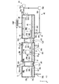
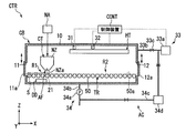
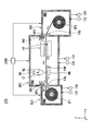
- the figure which shows the structure of the coating device which concerns on embodiment of this invention The figure which shows the structure of the application part of the coating device which concerns on this embodiment. The figure which shows the structure of the application part of the coating device which concerns on this embodiment. The figure which shows operation
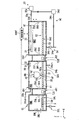
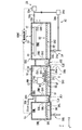
- FIG. 1 is a schematic diagram showing a configuration of a coating apparatus CTR according to the present embodiment.
- the coating device CTR includes a load lock device LL, a first chamber device CB1, and a second chamber device CB2.
- the load lock device LL, the first chamber device CB1, and the second chamber device CB2 are connected in series in the X direction, for example.
- the coating apparatus CTR is an apparatus that applies a liquid material on the substrate S.
- a plate-like member formed using a metal such as molybdenum is employed as the substrate S.
- the liquid composition includes a liquid material containing an easily oxidizable metal material such as copper (Cu), indium (In), gallium (Ga), and selenium (Se) in a solvent such as hydrazine. Is used.
- This liquid composition contains the metal material which comprises the light absorption layer (photoelectric converting layer) of a CIGS type solar cell or a CZTS type solar cell.
- the liquid material may be a liquid material in which other easily oxidizable metals are dispersed.
- the load lock device LL and the first chamber device CB1 are connected via the first connection chamber JC1.
- a first transfer device TJ1 for transferring the substrate S from the load lock device LL to the first chamber device CB1 is disposed.
- the first chamber device CB1 and the second chamber device CB2 are connected via a second connection chamber JC2.
- a second transfer device TJ2 for transferring the substrate S between the first chamber device CB1 and the second chamber device CB2 is disposed.
- the substrate S is loaded into the coating apparatus CTR from the load lock apparatus LL, and unloaded from the second chamber apparatus CB2 via the first chamber apparatus CB1. Therefore, in the coating apparatus CTR, the + X direction is the moving direction of the substrate S in principle.
- the load lock device LL includes a storage chamber RML, a substrate carry-in port ENL, and a substrate carry-out port EXL.
- the substrate carry-in port ENL is formed on the ⁇ X side wall of the storage chamber RML, and is connected to the outside, for example.
- the substrate carry-out port EXL is formed on the + X side wall of the storage chamber RML and is connected to the first connection chamber JC1.
- the substrate carry-in port ENL and the substrate carry-out port EXL are formed to dimensions that allow the substrate S to pass through.
- the accommodation chamber RML is provided with a substrate platform SPL for placing the substrate S and a substrate drive mechanism SAL for driving the substrate S.
- a decompression mechanism DCL such as a pump mechanism is connected to the storage chamber RML.
- the substrate driving mechanism SAL is a portion that transports the substrate S in the accommodation chamber RML.
- the substrate drive mechanism SAL has a plurality of roller members 50.
- the roller members 50 are arranged in the X direction from the substrate carry-in port ENL to the substrate carry-out port EXL.
- Each roller member 50 is provided to be rotatable around the Y axis with the Y axis direction as the central axis direction.
- the plurality of roller members 50 are formed so as to have the same diameter, and are arranged so that the positions in the Z direction are equal.
- the plurality of roller members 50 support the substrate S at the upper end on the + Z side.
- each roller member 50 is controlled by, for example, a roller rotation control unit (not shown).
- a roller rotation control unit for example, a roller transport mechanism may be used as shown in FIG. 1, or a floating transport mechanism (not shown) that lifts and transports the substrate may be used.
- a shutter member SHL is provided at each of the substrate carry-in entrance ENL and the substrate carry-out exit EXL. For example, by sliding the shutter member SHL in the Z direction, the substrate carry-in port ENL and the substrate carry-out port EXL are opened and closed. By closing the shutter member SHL, the storage chamber RML is sealed.
- the first chamber device CB1 has a storage chamber RM1, a substrate carry-in port EN1, and a substrate carry-out port EX1.
- the accommodation room RM1 is provided so as to accommodate the substrate S therein.
- the substrate carry-in port EN1 and the substrate carry-out port EX1 are openings formed in the accommodation chamber RM1.
- the substrate carry-in port EN1 is formed, for example, at the ⁇ X side end of the accommodation chamber RM1, and is connected to the first connection chamber JC1.
- the substrate carry-out port EX1 is formed, for example, at the + X side end of the accommodation chamber RM1, and is connected to the second connection chamber JC2.
- the substrate carry-in port EN1 and the substrate carry-out port EX1 are formed to dimensions that allow the substrate S to pass through.
- a shutter member SH1 is provided at each of the substrate carry-in entrance EN1 and the substrate carry-out exit EX1.
- the substrate carry-in entrance EN1 and the substrate carry-out exit EX1 are opened and closed by sliding the shutter member SH1 in the Z direction.
- the accommodation chamber RM1 is hermetically closed by closing the shutter member SH1.
- the accommodation chamber RM1 is provided with a substrate drive mechanism SA1, a coating unit CT, and a dummy discharge mechanism DD.
- an environment adjustment unit AC that adjusts the environment of the accommodation room RM1, for example, is connected to the accommodation room RM1.
- the substrate driving mechanism SA1 is a portion that transports the substrate S in the accommodation chamber RM1.
- the substrate driving mechanism SA1 has a plurality of roller members 51.
- the roller members 51 are arranged in the X direction from the substrate carry-in port EN1 to the substrate carry-out port EX1.
- the rotation of each roller member 51 is controlled by a roller rotation control unit (not shown).
- a roller conveyance mechanism may be used as in the case of the substrate driving mechanism SAL, or a floating conveyance mechanism that floats and conveys the substrate may be used.
- the coating part CT is accommodated in the accommodation chamber RM1 of the first chamber device CB1.
- the application part CT has a slit nozzle NZ formed in a long shape.
- the slit nozzle NZ is provided in the accommodation chamber RM1, for example, in the vicinity of the substrate carry-in port EN1.
- the slit nozzle NZ is formed to be long in the Y direction, for example.
- the slit nozzle NZ is disposed, for example, at a substantially central portion in the X direction of the accommodation chamber RM1. Spaces in which the substrate S can be arranged are secured on the + X side and the ⁇ X side of the slit nozzle NZ, respectively.
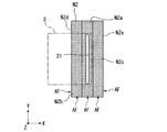
- FIG. 2A and 2B are diagrams showing the configuration of the slit nozzle NZ.
- FIG. 2A shows a configuration when the slit nozzle NZ is viewed in the + Z direction.
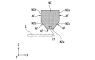
- FIG. 2B shows a configuration when the slit nozzle NZ is viewed in the + Y direction.
- the slit nozzle NZ is configured in a long shape with the Y direction as a longitudinal direction, for example.
- a slit-like nozzle opening 21 formed along the longitudinal direction of the slit nozzle NZ is provided at the tip end portion NZa of the slit nozzle NZ facing the ⁇ Z direction.
- the slit nozzle NZ is tapered so that the dimension in the X direction gradually decreases from the substantially central portion in the Z direction to the tip portion NZa toward the central portion in the X direction.
- a nozzle opening 21 is formed at substantially the center of the tip portion NZa of the slit nozzle NZ.
- the nozzle opening 21 is formed in the Y direction along the longitudinal direction of the slit nozzle NZ, for example. As shown in FIG. 2A, the nozzle opening 21 is formed, for example, such that the longitudinal direction is substantially the same as the dimension of the substrate S in the Y direction.
- the slit nozzle NZ discharges from the nozzle opening 21 a liquid material Q (see FIG. 3) in which, for example, the above four metals of Cu, In, Ga, and Se are mixed at a predetermined composition ratio.
- the slit nozzle NZ is connected to a liquid supply source (not shown) via a connection pipe (not shown).
- the slit nozzle NZ has a holding part for holding the liquid material therein.
- the slit nozzle NZ has a temperature adjustment mechanism (not shown) that adjusts the temperature of the liquid material held by the holding unit.
- the slit nozzle NZ is formed using a material containing, for example, titanium or a titanium alloy.
- a material containing, for example, titanium or a titanium alloy for example, at least one of the materials shown in (1) to (8) shown in Table 1 below is used. Of course, a plurality of materials (1) to (8) may be combined.
- the materials shown in the above (1) to (8) have the property that the affinity between the liquid materials Q having the above composition is weaker than the affinity between the liquid materials Q. More specifically, each of the materials shown in the above (1) to (8) has the property that the affinity between hydrazine contained in the liquid Q is weaker than the affinity between hydrazines. Yes. For this reason, the liquid Q is less likely to adhere to the slit nozzle NZ formed using the materials shown in the above (1) to (8).
- the entire slit nozzle NZ is formed using at least one of the materials (1) to (8). For this reason, on the entire surface of the slit nozzle NZ, a portion (affinity adjusting portion) AF having an affinity with the liquid material Q that is weaker than the affinity between the liquid materials Q is formed.
- the entire surface of the slit nozzle NZ includes, for example, a tip portion NZa and an adjacent portion adjacent to the tip portion NZa.
- the adjacent portion include inclined portions NZb and NZc respectively connected to the + X side end side and the ⁇ X side end side of the tip portion NZa of the slit nozzle NZ, as shown in FIGS. 2A and 2B.
- wall portions NZd and Nze connected to the + Z side of the inclined portions NZb and NZc, respectively, may be included.
- the slit nozzle NZ of the present embodiment is formed by using at least one of the materials (1) to (8), so that the affinity adjusting portion AF (for example, the tip portion NZa, the inclined portion NZb) is formed. And NZc, wall portions NZd and NZe, etc.) over the entire surface.
- the affinity between the material shown in the above (1) to (8) and hydrazine has a property that it is weaker than the affinity between molybdenum and hydrazine.
- the affinity between the materials shown in the above (1) to (8) and hydrazine is the affinity between the substrate S and hydrazine. It is weaker than that.
- the liquid Q is more easily attached to the substrate S formed using molybdenum than the slit nozzle NZ formed using the materials shown in the above (1) to (8).
- the slit nozzle NZ is formed so that the liquid Q discharged from the nozzle opening 21 is less likely to adhere to the slit nozzle NZ and more easily adheres to the substrate S.
- the slit nozzle NZ is provided with a nozzle drive mechanism NA (see FIG. 1).
- the nozzle drive mechanism NA has a configuration for driving the slit nozzle NZ in the X direction, the Y direction, and the Z direction.
- the nozzle drive mechanism NA has a configuration capable of moving the slit nozzle NZ between the standby position of the accommodation chamber RM1 and the application position (position shown in FIG. 1).
- the dummy discharge mechanism DD is provided at the standby position of the slit nozzle NZ.
- the dummy discharge mechanism DD performs, for example, a dummy discharge of a liquid material.
- the dummy discharge mechanism is provided with a bubble sensor (not shown) that detects bubbles in the liquid material, for example.
- the ⁇ Z side of the slit nozzle NZ is an application space R1 in which a liquid material is applied to the substrate S.
- the space on the + X side of the slit nozzle NZ is a part of the post-application movement space R2 of the substrate S.
- the second chamber device CB2 includes a storage chamber RM2, a substrate carry-in port EN2, and a substrate carry-out port EX2.
- the accommodation room RM2 is provided so as to accommodate the substrate S therein.
- the accommodation chamber RM2 becomes a part of the movement space R2 after the application of the substrate S.
- the substrate carry-in port EN2 and the substrate carry-out port EX2 are openings formed in the accommodation chamber RM2.
- the substrate carry-in port EN2 is formed, for example, at the ⁇ X side end of the accommodation chamber RM2, and is connected to the first connection chamber JC2.
- the substrate carry-out port EX2 is formed, for example, at the + X side end of the accommodation chamber RM2, and is connected to the outside.
- the substrate carry-in port EN2 and the substrate carry-out port EX2 are formed to dimensions that allow the substrate S to pass through.
- a shutter member SH2 is provided at each of the substrate carry-in port EN2 and the substrate carry-out port EX2.
- the substrate carry-in entrance EN2 and the substrate carry-out exit EX2 are configured to open and close by sliding the shutter member SH2 in the Z direction, for example.
- the accommodation chamber RM2 is hermetically closed by closing the shutter member SH2.
- the accommodation room RM2 is provided with a substrate driving mechanism SA2 and a heating unit HT.
- an environment adjustment unit AC that adjusts the environment of the accommodation room RM2, for example, is connected to the accommodation room RM2.
- the substrate drive mechanism SA2 is a portion that transports the substrate S in the accommodation chamber RM2, similarly to the substrate drive mechanisms SAL and SA1.
- the substrate driving mechanism SA2 has a plurality of roller members 52.
- the roller members 52 are arranged in the X direction from the substrate carry-in port EN2 to the substrate carry-out port EX2.
- the rotation of each roller member 52 is controlled by a roller rotation control unit (not shown).
- a roller transport mechanism may be used, or a floating transport mechanism that lifts and transports the substrate may be used.
- the heating part HT is a part for heating the liquid material applied on the substrate S.
- the heating unit HT includes a heating mechanism such as an infrared device, a hot plate, and an oven mechanism. In the heating part HT, by using the heating mechanism, for example, drying of the liquid material or firing of the liquid material is performed.
- the environment adjustment unit AC includes an oxygen concentration sensor 31, a pressure sensor 32, an inert gas supply unit 33, and an exhaust unit 34.
- One oxygen concentration sensor 31 and one pressure sensor 32 are provided in each of the storage chamber RM1 of the first chamber device CB1 and the storage chamber RM2 of the second chamber device CB2.
- the oxygen concentration sensor 31 detects the oxygen concentration in the accommodation room RM1 and the accommodation room RM2, and transmits the detection result to the control device CONT.
- the pressure sensor 32 detects the pressure in the accommodation chamber RM1 and the accommodation chamber RM2, and transmits the detection result to the control device CONT.
- the oxygen concentration sensor 31 and the pressure sensor 32 are configured to be attached to the ceiling portions of the storage chamber RM1 and the storage chamber RM2, but may be configured to be provided in other portions. I do not care.
- the inert gas supply unit 33 supplies an inert gas such as nitrogen gas, argon gas, or helium gas into the accommodation room RM1 and the accommodation room RM2.
- the inert gas supply unit 33 includes a gas supply source 33a, a pipe 33b, and a supply amount adjustment unit 33c.
- a gas cylinder or the like can be used as the gas supply source 33a.
- the pipe 33b has one end connected to the gas supply source 33a and the other end branched and connected to the accommodation room RM1 and the accommodation room RM2.
- the ends connected to the accommodation chamber RM1 and the accommodation chamber RM2 in the pipe 33b serve as inert gas supply ports in the accommodation chamber RM1 and the accommodation chamber RM2, respectively.
- the inert gas supply port is, for example, a wall portion on the ⁇ X side of the storage chamber RM1 and is disposed near the ceiling. Further, the inert gas supply port is, for example, a wall portion on the + X side of the storage chamber RM2 and is disposed near the ceiling.
- the supply amount adjusting unit 33c is a part that adjusts the supply amount of the inert gas supplied to the storage chamber RM1 and the storage chamber RM2.
- As the supply amount adjusting unit 33c for example, an electromagnetic valve or a valve that is manually opened and closed can be used.
- the supply amount adjusting unit 33c is provided in the pipe 33b, for example.
- the exhaust part 34 discharges the gas in the accommodation room RM1 and the accommodation room RM2 to the outside.
- the exhaust part 34 is also used when the gas in the accommodation chamber RM1 and the accommodation chamber RM2 is exhausted to decompress the accommodation chamber RM1 and the accommodation chamber RM2.
- the exhaust unit 34 includes an exhaust drive source 34a, a pipe 34b, a pipe 34c, and a removal member 34d.
- the exhaust drive source 34a is branched and connected to the interior of the accommodation room RM1 and the accommodation room RM2 via the pipe 34b.
- a pump or the like is used as the exhaust drive source 34a.
- the pipe 34b has an exhaust port at an end provided inside the accommodation room RM1 and the accommodation room RM2. This exhaust port is disposed, for example, at the bottom (the surface on the ⁇ Z side) of each of the storage chamber RM1 and the storage chamber RM2.
- the inert gas supply port is disposed on the + Z side of the storage chamber RM1 and the storage chamber RM2, and the exhaust port is disposed on the ⁇ Z side of the storage chamber RM1 and the storage chamber RM2.
- the pipe 34 c has one end connected to the exhaust drive source 34 a and the other end connected to the pipe 33 b of the inert gas supply unit 33.
- the pipe 34c serves as a circulation path for circulating the gas in the storage chamber RM1 and the storage chamber RM2 exhausted by the exhaust drive source 34a to the supply path.
- the exhaust part 34 also serves as a circulation mechanism that circulates the gas in the accommodation chamber RM1 and the accommodation chamber RM2.
- the connection destination of the pipe 34c is not limited to the pipe 33b of the inert gas supply unit 33.
- the pipe 34c may be directly connected to the storage chamber RM1 and the storage chamber RM2.
- valves are provided on the upstream side and the downstream side of the removing member 34d, respectively, in the pipe 34c.
- the removal member 34d is provided in the pipe 34c.
- As the removal member 34d for example, an adsorbent that adsorbs an oxygen component and moisture in a gas flowing through the pipe 34c is used. For this reason, the gas to circulate can be cleaned.
- the removal member 34d may be configured to be disposed at one place in the pipe 34c, or may be configured to be disposed over the entire pipe 34c.
- the control device CONT is a part that comprehensively controls the coating device CTR. Specifically, the control device CONT controls the operations of the load lock device LL, the first chamber device CB1, the second chamber device CB2, and the environment adjustment unit AC. For example, the shutter members SHL, SH1, and SH2 are controlled to open and close, the substrate drive mechanisms SAL, SA1, and SA2 operate, the application operation by the application unit CT, the heating operation by the heating unit HT, and the adjustment operation by the environment adjustment unit AC.
- the control device CONT adjusts the opening degree of the supply amount adjustment unit 33c of the inert gas supply unit 33 based on the detection results by the oxygen concentration sensor 31 and the pressure sensor 32.
- the control device CONT has a timer (not shown) used for measuring processing time, for example.
- the control device CONT keeps the shutter members SHL, SH1, and SH2 provided in the coating device CTR in a closed state. In this state, when the substrate S is transferred from the outside to the coating device CTR, the control device CONT sets the shutter member SHL provided in the substrate loading port ENL of the load lock device LL in an opened state from the substrate loading port ENL. The substrate S is carried into the accommodation room RML.
- the control device CONT closes the shutter member SHL of the substrate carry-in port ENL and closes the accommodation chamber RML.
- the control device CONT puts the accommodation room RML in a sealed state and then puts the accommodation room RML in a reduced pressure state using the decompression mechanism DCL.
- the control device CONT After confirming that the storage chamber RM1 of the first chamber device CB1 and the storage chamber RM2 of the second chamber device CB2 are in a sealed state, the control device CONT changes the atmosphere of the storage chambers RM1 and RM2 to an inert gas atmosphere. To adjust. Specifically, the inert gas is supplied to the storage chamber RM1 and the storage chamber RM2 using the inert gas supply unit 33. In this case, the control device CONT may adjust the pressures in the storage chambers RM1 and RM2 by operating the exhaust unit 34 as appropriate.
- control device CONT holds the liquid material in the holding portion of the slit nozzle NZ.
- the control device CONT adjusts the temperature of the liquid material held by the holding unit using a temperature control mechanism in the slit nozzle NZ. As described above, the control device CONT prepares a state in which the liquid material is discharged onto the substrate S.
- the control device CONT opens the substrate carry-out port EXL of the load lock device LL and the substrate carry-in port EN1 of the first chamber device CB1, as shown in FIG.
- the substrate S is loaded from the LL through the first connection chamber JC1 into the accommodation chamber RM1 of the first chamber device CB1.
- the control device CONT After carrying in the substrate S, the control device CONT rotates the roller member 51 of the substrate driving mechanism SA1 to move the substrate S in the + X direction.
- the control device CONT uses the slit nozzle NZ to apply a liquid material to the substrate S as shown in FIG. Q is applied.
- control device CONT moves the slit nozzle NZ and the substrate S relative to each other (in the present embodiment, the substrate S is moved in the + X direction) so that the tip portion NZa of the slit nozzle NZ faces the substrate S.
- the control device CONT opens the liquid material from the nozzle opening 21 so that the liquid material is sandwiched between the front end portion NZa and the substrate S as shown in FIG. Q is discharged.
- the affinity with the liquid material Q in the tip portion NZa is stronger than the affinity between the liquid materials Q, the liquid material Q tends to contact the tip portion NZa rather than in contact with the liquid materials Q. . For this reason, the liquid material Q is in a state of adhering to the tip portion NZa, and the fixability to the substrate S is deteriorated. Further, when the affinity with the liquid material Q in the inclined portions NZb and NZc which are adjacent portions as well as the tip portion NZa is stronger than the affinity between the liquid materials Q, the liquid material Q is inclined from the tip portion NZa. It is transmitted to NZb and NZc, and the fixability to the substrate S is further deteriorated.
- the liquid material Q in the front end portion NZa (and the adjacent portion) is stronger than the affinity between the liquid material Q and the substrate S, the liquid material Q has the front end portion NZa (and the adjacent portion) more than the substrate S. In this case, the fixability to the substrate S is deteriorated.
- the slit nozzle NZ is entirely formed using at least one of the materials shown in (1) to (8) of Table 1 above.
- the affinity with the liquid Q in the tip portion NZa (affinity adjusting part AF) of NZ is weaker than the affinity between the liquids Q. Further, the affinity of the tip portion NZa with the liquid material Q is weaker than the affinity between the substrate S and the liquid material Q.
- the liquid material Q becomes difficult to adhere to the tip portion NZa and the liquid materials Q are easily in contact with each other. It becomes a state. Further, the liquid Q is more likely to adhere to the substrate S than the tip portion NZa.
- the control device CONT moves the substrate S while discharging the liquid material Q from the nozzle opening 21.
- the liquid Q is arranged and fixed on the substrate S without flowing from the tip portion NZa to the inclined portion NZb, the inclined portion NZc, or the like.
- the liquid material Q applied on the substrate S pulls the liquid material Q of the tip portion NZa.
- the coating film L of the liquid material is formed on the predetermined region of the substrate S with a substantially uniform film thickness.
- the control device CONT accommodates the substrate S on which the coating film L is formed in the accommodation chamber RM2 of the second chamber device CB2. Specifically, as shown in FIG. 7, the control device CONT opens the substrate carry-in port EX1 of the storage chamber RM1 and the substrate carry-in port EN2 of the storage chamber RM2, and opens the substrate carry-out port EX1 and the second connection chamber JC2. Then, the substrate S is carried into the storage chamber RM2 through the substrate carry-in port EN2.
- the control device CONT after carrying the substrate S into the storage chamber RM2, moves the substrate S so as to be positioned on the ⁇ Z side of the heating unit HT, and then operates the exhaust unit 34, as shown in FIG. Thus, the storage chamber RM2 is decompressed. After depressurizing the storage chamber RM2, the control device CONT operates the heating unit HT to heat the coating film L on the substrate S. By heating the liquid under reduced pressure, the coating film L is efficiently dried in a short time.
- This drying operation may be performed only by heat treatment without reducing the pressure in the storage chamber RM2.
- this drying operation may be performed only by the decompression process of the storage chamber RM2 without being heated. Further, the heat treatment may be performed after the pressure reduction treatment.
- the heating temperature in the heating step is, for example, 300 ° C. or less. Further, for example, the temperature is set to 50 ° C. or higher. By setting the heating temperature to 300 ° C. or lower, even if the constituent material of the substrate S is a resin material, the heat treatment is performed without causing the substrate S to be deformed. For this reason, the range of selection of the material of the substrate S is widened.
- the control device CONT stops the rotation operation of the roller member 52 and operates the heating unit HT in a state where the movement of the substrate S is stopped. For example, the time until the coating film L on the substrate S is dried and the heating temperature are stored in advance, and the controller CONT adjusts the heating time and the heating temperature using the stored values. The heating operation of the coating film L is performed.
- the substrate S may pass under the heating unit HT while the roller member 52 is rotated.
- the heating unit HT may have a temperature gradient from the X minus direction to the X plus direction. In that case, the substrate S is gradually heated, heated at a desired temperature for a set time, and then gradually cooled, so that the substrate S or a film containing an easily oxidizable metal applied on the substrate S is formed. Can be dried without stress.
- the liquid material Q containing the easily oxidizable metal is applied on the substrate S to form a part of the light absorption layer, for example, Cu or In is a metal that easily oxidizes (easy to oxidize). Therefore, if the oxygen concentration in the storage chamber RM1 and the storage chamber RM2 is high, the oxidizable metal is oxidized. If these metals are oxidized, the quality of the coating film formed on the substrate S may be deteriorated.
- the control device CONT uses the environment adjustment unit AC to adjust the accommodation room RM1 and the accommodation room RM2 to be in an inert gas atmosphere. Specifically, the control device CONT uses the inert gas supply unit 33 to supply an inert gas such as nitrogen gas or argon gas to the storage chamber RM1 and the storage chamber RM2.
- an inert gas such as nitrogen gas or argon gas
- the control device CONT first detects the oxygen concentrations of the storage chamber RM1 and the storage chamber RM2 by the oxygen concentration sensor 31. Based on the detection result in the detection step, the control device CONT adjusts the supply amount of the inert gas using the supply amount adjusting unit 33c, and supplies the inert gas to the storage chamber RM1 and the storage chamber RM2. For example, when the detected oxygen concentration exceeds a preset threshold value, the inert gas can be supplied to the storage chamber RM1 and the storage chamber RM2.
- the threshold value can be obtained in advance by experiments or simulations and stored in the control device CONT.
- a constant amount of inert gas is always supplied to the storage chamber RM1 and the storage chamber RM2 during the coating operation and the drying operation, and the supply amount is determined based on the detection result of the oxygen concentration sensor 31. You can make it more or less.
- the control device CONT uses the oxygen concentration sensor 31 and simultaneously detects the atmospheric pressure in the accommodation chamber RM1 and the accommodation chamber RM2 by the pressure sensor 32. Based on the detection result of the pressure sensor 32, the control device CONT adjusts the supply amount of the inert gas using the supply amount adjusting unit 33c, and supplies the inert gas to the storage chamber RM1 and the storage chamber RM2. For example, when the atmospheric pressure in the accommodation room RM1 and the accommodation room RM2 exceeds a preset threshold, the exhaust room 34 is used to exhaust the accommodation room RM1 and the accommodation room RM2. This threshold value can also be obtained in advance by experiments or simulations and stored in the control device CONT.
- the accommodation chamber RM1 and the accommodation chamber RM2 are always exhausted at a constant amount, and the exhaust amount is increased or decreased based on the detection result of the pressure sensor 32. It can also be made. In this way, the accommodation room RM1 and the accommodation room RM2 are held under reduced pressure.
- the gas exhausted from the exhaust unit 34 is circulated through the piping 34 b and the piping 34 c to the piping 33 b of the inert gas supply unit 33.
- this gas passes through the removal member 34d.
- the oxygen component in the gas is adsorbed and removed by the removing member 34d.
- the inert gas with a low oxygen concentration is circulated through the pipe 33b.
- the tip portion NZa of the slit nozzle NZ is formed so that the affinity with the liquid material Q is weaker than the affinity between the liquid materials Q. Since the affinity adjusting portion AF is provided, it is possible to suppress the liquid Q discharged from the tip portion NZa of the slit nozzle NZ from adhering to the tip portion NZa. Thereby, since the liquid Q is easily fixed on the substrate S, the liquid Q can be applied to the substrate S without unevenness.
- the slit nozzle NZ may have a covering portion NZf formed so as to cover the tip portion NZa, the inclined portions NZb and NZc, and the wall portions NZd and NZe.
- the covering portion NZf is formed using at least one material of the above (1) to (8).
- the coating part NZf having the above-described configuration can be formed by coating the surface of the slit nozzle NZ or performing vapor deposition. Even when the covering portion NZf is provided on the surface of the slit nozzle NZ, the affinity adjusting portion AF is formed in the portion where the covering portion NZf is provided.
- the portion of the slit nozzle NZ other than the covering portion NZf may be made of a material different from the materials (1) to (8).
- the said embodiment although it was set as the structure which has arrange
- the application unit CT and the heating unit HT may be arranged in the same space in one chamber device CB. In this case, the space on the ⁇ Z side of the application part CT becomes the application space R1, and the space on the + X side of the application space becomes the post-application movement space R2.
- the space in the chamber CB may be divided into two so that the slit nozzle NZ and the heating unit HT are arranged in different spaces.
- a partition member 110 is provided in the chamber CB. The partition member 110 is disposed in the transport direction of the substrate S. The substrate S is transported beyond the partition member 110.
- An opening 111 is formed in a region corresponding to the height position (position in the Z direction) of the substrate S in the partition member 110.
- the opening 111 is provided with a lid 111a so that the opening 111 can be opened and closed.
- the lid 111a is opened to allow the substrate S to pass therethrough.
- the lid 111a is closed.
- the oxygen concentration sensor 31 for detecting the oxygen concentration in the chamber CB and the pressure sensor 32 for detecting the pressure are provided in each space partitioned by the partition member 110, respectively.
- the environment adjustment unit is also connected to each of the two spaces.
- An environment adjusting unit AC1 is connected to a space in which the slit nozzle NZ is disposed.
- the configuration of the environment adjustment unit AC1 is the same as the configuration of the environment adjustment unit AC in the first embodiment.
- the environment adjustment unit AC2 is connected to the space where the heating unit HT is provided.
- the environment adjustment unit AC2 is provided with a branch pipe 125 that branches from the pipe 34c. Therefore, similarly to the pipe 34c, the gas exhausted by the exhaust drive source 34a flows through the branch pipe 125.
- the branch pipe 125 is connected to the heat storage mechanism 120, for example.
- a heating mechanism 121 for heating the gas flowing through the branch pipe 125 is provided on the branch pipe 125.
- the branch pipe 125 may have a configuration in which a removing member for removing oxygen (for example, the same member as the removing member 34d of the first embodiment) is provided.
- the heating unit HT includes a heat storage mechanism 120 and a hot plate 130.
- the heat storage mechanism 120 is disposed on the ceiling side of the chamber CB with respect to the transfer region of the substrate S, and the hot plate 130 is disposed on the bottom side of the chamber CB with respect to the transfer region of the substrate S.
- the hot plate 130 is provided with a heating mechanism (not shown) as in the heating unit HT of the first embodiment.
- the heat storage mechanism 120 can store the heat of the gas in the chamber CB. Further, the heat storage mechanism 120 is supplied with a gas flowing through the branch pipe 125. For this reason, in the heat storage mechanism 120, the temperature of the supplied gas is adjusted to a temperature substantially the same as the temperature in the chamber CB.
- the heat storage mechanism 120 has an opening on the ⁇ Z side, and the gas from the branch pipe 125 flows into the chamber CB through the opening.
- the control device CONT first causes the substrate S to perform the coating step in the space where the slit nozzle NZ is arranged. After the application step is completed, the control device CONT opens the lid 111a and transports the substrate S to the space where the heating unit HT is arranged.
- the controller CONT After transporting the substrate S, the controller CONT depressurizes the space in which the heating unit HT is disposed with the lid 111a closed. After depressurization, the control device CONT operates the heating unit HT to perform a heating step on the liquid on the substrate S.
- the heating step the substrate S is heated from both the front and back sides by the heat storage mechanism 120 and the hot plate 130.
- gas for example, inert gas
- gas supplied to the heat storage mechanism 120 is heated by the stored heat, and the temperature is adjusted to substantially the same temperature as in the space (gas heating step). This gas is supplied into the space from the opening of the heat storage mechanism 120 and is reused.
- the gas may be heated using the heating mechanism 121 provided in the branch pipe 125.
- the control device CONT stops the operation of the heating unit HT and returns the pressure in the chamber CB (in the space) to atmospheric pressure. Thereafter, the control device CONT opens the lid 12a while keeping the lid 111a closed, transports the substrate S in the + X direction, and unloads the substrate S.
- liquid material Q is applied onto the substrate S by moving the substrate S while the slit nozzle NZ is fixed when performing the application operation.
- the liquid material Q may be applied onto the substrate S by moving the slit nozzle NZ while the substrate S is fixed. Further, both the substrate S and the slit nozzle NZ may be moved.
- FIG. 12 is a diagram showing another configuration of the coating apparatus CTR.
- the coating apparatus CTR includes a substrate carry-in chamber SLC, a substrate processing chamber SPC, a substrate carry-out chamber SUC, and a control device CONT that controls these.
- the substrate carry-in chamber SLC has a storage chamber RMA for storing the film substrate F formed in a strip shape.
- the accommodation room RMA is provided with a shaft portion SF1 around which the film substrate F is wound.
- the shaft portion SF1 is disposed so as to extend in the Y direction, and is provided to be rotatable in the ⁇ Y direction.
- the storage chamber RMA is connected to the inert gas supply unit 133 and the exhaust unit 134.
- the accommodation chamber RMA is provided with a substrate transport mechanism FAL for transporting the film substrate F.
- As the substrate transport mechanism FAL for example, a roller mechanism can be used.
- the substrate processing chamber SPC has a storage room RMB.
- the accommodation room RMB is connected to the accommodation room RMA of the substrate carry-in chamber SLC through the opening OP1.
- the accommodation chamber RMB is provided with a coating part CT, a substrate transport part FAP, a heating part HT, a nozzle tip management part MN, a carry-in side shutter part SH1, and a carry-out side shutter part SH2.
- the storage chamber RMB is connected to the inert gas supply unit 133 and the exhaust unit 134.
- the coating part CT has a nozzle NZ and a nozzle drive mechanism NA.
- the nozzle NZ has, for example, a tapered end at the ⁇ Z side.
- the nozzle NZ is provided so that a liquid material can be discharged from an end (tip) on the ⁇ Z side.
- the nozzle drive mechanism NA drives the nozzle NZ in the X direction, the Y direction, the Z direction, and the like as necessary.
- the substrate transport unit FAP is configured to transport the film substrate F to the ⁇ Z side of the nozzle NZ.
- the substrate transport unit FAP has a plurality of roller units. By combining the arrangement of the roller portions, the transport path of the film substrate F is set so as to pass through the ⁇ Z side of the nozzle NZ.
- the heating sections HT are arranged one by one on the + Z side and the ⁇ Z side of the transport path of the film substrate F so as to sandwich the film substrate F in the Z direction.
- the heating unit HT for example, the same heating unit HT as the configuration of the above embodiment is used.
- the nozzle tip management unit MN maintains the tip of the nozzle NZ.
- the nozzle tip management unit MN is arranged, for example, within a movable range of the nozzle NZ, a portion that cleans the tip of the nozzle NZ, a portion that performs preliminary discharge of the nozzle NZ, a portion that dries the tip of the nozzle NZ, Etc. are provided.
- the loading-side shutter unit SH1 is an opening / closing mechanism that opens and closes between the accommodation room RMA of the substrate carry-in chamber SLC and the accommodation room RMB of the substrate processing chamber SPC.
- the carry-in shutter part SH1 is provided so as to be movable in the Z direction by a drive mechanism (not shown).
- FIG. 12 shows a state where the carry-in shutter unit SH1 is in an open state.
- the unload-side shutter unit SH2 is an opening / closing mechanism that opens and closes between the storage chamber RMB and the storage chamber RMC of the substrate transfer chamber SUC.
- the carry-out shutter unit SH2 is provided so as to be movable in the Z direction by a drive mechanism (not shown).
- FIG. 12 shows a state where the carry-out side shutter part SH2 is in an open state.
- the substrate carry-out chamber SUC has a storage chamber RMC for storing the film substrate F.
- the accommodation room RMC is connected to the accommodation room RMB of the substrate processing chamber SPC through the opening OP2.
- the accommodation room RMC is provided with a shaft portion SF2 for winding the film substrate F.
- the shaft portion SF2 is disposed so as to extend in the Y direction, and is provided to be rotatable in the ⁇ Y direction.
- the storage chamber RMC is connected to the inert gas supply unit 133 and the exhaust unit 134.
- the accommodation chamber RMC is provided with a substrate transport mechanism FAU for transporting the film substrate F.
- As the substrate transport mechanism FAU for example, a roller mechanism can be used.
- the control device CONT opens the loading-side shutter unit SH1 and the unloading-side shutter unit SH2, and then appropriately adjusts the supply amount by the inert gas supply unit 133 and the exhaust amount by the exhaust unit 134, and the storage chamber RMA and the storage unit The environment of the room RMB and the accommodation room RMC is adjusted.
- the control device CONT rotates the shaft portion SF1 in the + ⁇ Y direction and transports the film substrate F to the + X side.
- the film substrate F is conveyed from the accommodation room RMA to the accommodation room RMB through the opening OP1.
- the control device CONT transports the film substrate F to the + X side by rotating a roller portion that constitutes the substrate transport mechanism FAP in the accommodation chamber RMB.
- the control device CONT discharges the liquid material from the nozzle NZ toward the film substrate F for a certain period of time.
- the liquid material Q is applied to a predetermined region of the film substrate F.
- the coating film of the liquid material Q can be formed for each predetermined region on the film substrate F that continuously passes through the ⁇ Z side of the nozzle NZ.
- the control device CONT activates at least one of the two heating units HT to perform a drying process or a heating process on the liquid Q applied on the film substrate F.
- the control device CONT carries out the part of the film substrate F that has been subjected to the drying process or the heating process to the accommodation room RMC of the substrate carry-out chamber SUC through the opening OP2.
- the control device CONT rotates the shaft portion SF2 and winds the film substrate F around the shaft portion SF2.
- the control device CONT closes the carry-in side shutter part SH1 and the carry-out side shutter part SH2.
- the storage room RMA and the storage room RMB are blocked, and the storage room RMB and the storage room RMC are blocked.
- the loading-side shutter portion SH1 is closed and the shaft portion SF1 is replaced.
- the unloading-side shutter portion SH2 is closed and the shaft portion SH2 is replaced.
- the present invention can be applied even when the liquid material Q is applied onto a continuous belt-like film.
- CTR ... coating device LL ... load lock device CB1 ... first chamber device CB2 ... second chamber device RML, RM1, RM2 ... storage chamber SAL, SA1, SA2 ... substrate drive mechanism CT ... coating part NZ ... slit nozzle NZa ... tip part Q ... Liquid material AF ... Affinity adjustment part NA ... Nozzle drive mechanism R1 ... Application space R2 ... Movement space after application HT ... Heating part CONT ... Control device 21 ... Nozzle opening S ... Substrate
Landscapes
- Coating Apparatus (AREA)
- Photovoltaic Devices (AREA)
- Engineering & Computer Science (AREA)
- Manufacturing & Machinery (AREA)
- Application Of Or Painting With Fluid Materials (AREA)
Abstract
易酸化性の金属とヒドラジンとを含む液状体(Q)を先端部分(NZa)から吐出するノズル(NZ)を有する塗布部(CT)と、基板(S)と前記ノズル(NZ)とを相対移動させる相対駆動部(NA)とを備える塗布装置において、ノズル(NZ)のうち少なくとも先端部分(NZa)には、液状体(Q)との間の親和性が液状体(Q)同士の親和性よりも弱くなるように形成された親和性調整部(AF)を設けたものである。 当該構成により、基板上に液状体をムラなく塗布できる。
Description
本発明は、塗布装置及び塗布方法に関するものである。
本願は、2010年10月13日に、日本に出願された特願2010-230573号に基づき優先権を主張し、その内容をここに援用する。
本願は、2010年10月13日に、日本に出願された特願2010-230573号に基づき優先権を主張し、その内容をここに援用する。
Cu、Ge、Sn、Pb、Sb、Bi、Ga、In、Ti、Znおよびこれらの組合せなどの金属と、S、Se、Te、およびこれらの組合せなどの元素カルコゲンとを含む半導体材料を用いたCIGS型太陽電池やCZTS型太陽電池は、高い変換効率を有する太陽電池として注目されている(例えば特許文献1~特許文献3参照)。例えば、CIGS型太陽電池は、光吸収層(光電変換層)として上記、Cu、In、Ga、Seの4種類の半導体材料からなる膜を用いる構成になっている。
CIGS型太陽電池やCZTS型太陽電池は、従来型の太陽電池に比べて光吸収層の厚さを薄くすることができるため、曲面への設置や運搬が容易となる。このため、高性能でフレキシブルな太陽電池として、広い分野への応用が期待されている。光吸収層を形成する手法として、従来、例えば蒸着法やスパッタリング法などを用いて形成する手法が知られていた(例えば、特許文献3~特許文献5参照)。
これに対して、本発明者は、光吸収層を形成する手法として、上記半導体材料を分散させた液状体をノズルによって基板上に吐出し、前記液状体の膜を基板上に塗布する手法を提案する。光吸収層を液状体の塗布によって形成する場合、基板上に形成される液状体の膜厚が均一になるように基板上に液状体をムラ無く塗布することが求められる。
以上のような事情に鑑み、本発明は、基板上に液状体をムラ無く塗布することが可能な塗布装置及び塗布方法を提供することを目的とする。
本発明の第一の態様は、先端部分に設けられた吐出部から易酸化性の金属を含む液状体を吐出するノズルを有する塗布部と、前記先端部分と前記基板とを対向させた状態で前記基板と前記ノズルとを相対移動させる相対駆動部とを備え、前記ノズルのうち少なくとも前記先端部分には、前記液状体との間の親和性が前記液状体同士の親和性よりも弱くなるように形成された親和性調整部が設けられている塗布装置である。
本発明の第一の態様によれば、ノズルのうち少なくとも先端部分に、液状体との間の親和性が液状体同士の親和性よりも弱くなるように形成された親和性調整部が設けられているので、ノズルの先端部分から吐出された液状体が前記先端部分に付着するのを抑制することができる。これにより、液状体が基板に定着しやすくなるため、基板上に液状体をムラ無く塗布することが可能となる。
上記の塗布装置において、好ましくは、前記親和性調整部は、前記ノズルのうち、前記先端部分と、前記先端部分に隣接する部分と、を含む部分に設けられている。
この場合、親和性調整部がノズルのうち先端部分と、前記先端部分に隣接する部分とを含む部分に設けられているため、液状体がノズルの先端部分から前記先端部分に隣接する部分へ伝ってしまうのを防ぐことができる。
この場合、親和性調整部がノズルのうち先端部分と、前記先端部分に隣接する部分とを含む部分に設けられているため、液状体がノズルの先端部分から前記先端部分に隣接する部分へ伝ってしまうのを防ぐことができる。
上記の塗布装置において、好ましくは、前記液状体は、ヒドラジンを含み、前記親和性調整部は、前記ヒドラジンとの間の親和性が前記ヒドラジン同士の親和性よりも弱くなるように形成されている。
この場合、液状体がヒドラジンを含み、親和性調整部がヒドラジンとの間の親和性がヒドラジン同士の親和性よりも弱くなるように形成されているため、ノズルの先端部分から吐出されたヒドラジンを含む液状体が前記先端部分に付着するのを抑制することができる。これにより、ヒドラジンを含む液状体が基板に定着しやすくなるため、基板上に液状体をムラ無く塗布することが可能となる。
上記の塗布装置において、好ましくは、前記親和性調整部は、前記ヒドラジンとの間の親和性が前記ヒドラジンと前記基板との間の親和性よりも弱くなるように形成されている。
この場合、ヒドラジンとの間の親和性がヒドラジンと基板との間の親和性よりも弱くなるように親和性調整部が形成されているため、ヒドラジンを含む液状体が先端部分の親和性調整部よりも基板に定着しやすくなる。これにより、基板上に液状体をムラ無く塗布することが可能となる。
この場合、ヒドラジンとの間の親和性がヒドラジンと基板との間の親和性よりも弱くなるように親和性調整部が形成されているため、ヒドラジンを含む液状体が先端部分の親和性調整部よりも基板に定着しやすくなる。これにより、基板上に液状体をムラ無く塗布することが可能となる。
上記の塗布装置において、好ましくは、前記親和性調整部は、チタン及びチタン合金のうち少なくとも一方を用いて形成されている。
この場合、親和性調整部としてチタン及びチタン合金のうち少なくとも一方を用いて形成されているため、液状体が基板に定着しやすくなる。これにより、基板上に液状体をムラ無く塗布することが可能となる。
この場合、親和性調整部としてチタン及びチタン合金のうち少なくとも一方を用いて形成されているため、液状体が基板に定着しやすくなる。これにより、基板上に液状体をムラ無く塗布することが可能となる。
上記の塗布装置において、好ましくは、前記基板は、モリブデンを用いて形成されている。
この場合、モリブデンを用いて形成された基板に液状体が定着しやすくなるため、基板上に液状体をムラ無く塗布することが可能となる。
この場合、モリブデンを用いて形成された基板に液状体が定着しやすくなるため、基板上に液状体をムラ無く塗布することが可能となる。
上記の塗布装置において、好ましくは、前記金属は、銅、インジウム、ガリウム及びセレンのうち少なくとも1つを含む。
この場合、金属として、銅、インジウム、ガリウム及びセレンのうち少なくとも1つを含む液状体が基板に定着しやすくなるため、基板上に液状体をムラ無く塗布することが可能となる。
この場合、金属として、銅、インジウム、ガリウム及びセレンのうち少なくとも1つを含む液状体が基板に定着しやすくなるため、基板上に液状体をムラ無く塗布することが可能となる。
上記の塗布装置において、好ましくは、前記塗布部によって前記液状体の塗布される塗布空間及び前記液状体の塗布された前記基板の塗布後移動空間のうち少なくとも一方の空間を囲むチャンバを更に備える。
この場合、塗布部によって液状体の塗布される塗布空間及び液状体の塗布された基板の塗布後移動空間のうち少なくとも一方の空間を囲むチャンバにより、液状体の配置される空間が囲まれるため、液状体の劣化を防ぐことができる。
この場合、塗布部によって液状体の塗布される塗布空間及び液状体の塗布された基板の塗布後移動空間のうち少なくとも一方の空間を囲むチャンバにより、液状体の配置される空間が囲まれるため、液状体の劣化を防ぐことができる。
上記の塗布装置において、好ましくは、前記チャンバで囲まれた前記空間に不活性ガスを供給する不活性ガス供給部を更に備える。
この場合、チャンバで囲まれた空間に不活性ガスが供給されるため、前記チャンバに囲まれた空間において液状体の劣化をより確実に防ぐことができる。
この場合、チャンバで囲まれた空間に不活性ガスが供給されるため、前記チャンバに囲まれた空間において液状体の劣化をより確実に防ぐことができる。
上記の塗布装置において、好ましくは、前記塗布部における吐出部は、前記先端部分に対向する吐出領域に前記液状体を吐出するように形成されており、前記相対駆動部は、前記吐出領域を通過するように前記基板を搬送する基板搬送部を有する。
この場合、塗布部が先端部分に対向する吐出領域に液状体を吐出するように形成されており、相対駆動部が吐出領域を通過するように基板を搬送する基板搬送部を有するため、例えばノズルを駆動させずに基板を搬送することにより、基板上に液状体をムラ無く塗布することが可能となる。
この場合、塗布部が先端部分に対向する吐出領域に液状体を吐出するように形成されており、相対駆動部が吐出領域を通過するように基板を搬送する基板搬送部を有するため、例えばノズルを駆動させずに基板を搬送することにより、基板上に液状体をムラ無く塗布することが可能となる。
上記の塗布装置において、好ましくは、前記塗布部における吐出部は、前記先端部分に対向する吐出領域に前記液状体を吐出するように形成されており、前記相対駆動部は、前記吐出領域が前記基板上を走査するように前記ノズルを駆動するノズル駆動部を有する。
この場合、塗布部が先端部分に対向する吐出領域に液状体を吐出するように形成されており、相対駆動部が吐出領域が基板上を走査するようにノズルを駆動するノズル駆動部を有するため、例えば基板を駆動させずにノズルを駆動することにより、基板上に液状体をムラ無く塗布することが可能となる。また、相対駆動部が基板搬送部及びノズル駆動部の両方を備える構成とすることもできる。この場合、相対移動としては、例えば基板を移動させる、ノズルを移動させる、基板及びノズルの両方を移動させる、といった態様を取りうる。
この場合、塗布部が先端部分に対向する吐出領域に液状体を吐出するように形成されており、相対駆動部が吐出領域が基板上を走査するようにノズルを駆動するノズル駆動部を有するため、例えば基板を駆動させずにノズルを駆動することにより、基板上に液状体をムラ無く塗布することが可能となる。また、相対駆動部が基板搬送部及びノズル駆動部の両方を備える構成とすることもできる。この場合、相対移動としては、例えば基板を移動させる、ノズルを移動させる、基板及びノズルの両方を移動させる、といった態様を取りうる。
本発明の第二の態様は、易酸化性の金属を含む液状体を基板に塗布する塗布方法であって、前記液状体との間の親和性が前記液状体同士の親和性よりも弱くなるように形成された親和性調整部が設けられる先端部分に形成された吐出部から前記液状体を吐出するノズルを有する塗布部の前記先端部分を前記基板に対向させるステップと、前記先端部分と前記基板との間で前記液状体が挟持されるように、前記吐出部から前記液状体を吐出するステップと、前記先端部分と前記基板との間で前記液状体を挟持した状態で、前記吐出部から前記液状体を吐出しつつ前記先端部分と前記基板とを相対移動させるステップとを含む塗布方法である。
本発明の第二の態様によれば、液状体との間の親和性が液状体同士の親和性よりも弱くなるように形成された親和性調整部が先端部分に設けられており、前記先端部分に液状体の吐出部が形成されたノズルの前記先端部分を基板に対向させ、先端部分と基板との間で液状体が挟持されるように吐出部から液状体を吐出することで、液状体は先端部分に付着しにくい状態になると共に、液状体同士で接触しやすい状態となる。この状態で吐出部から液状体を吐出しつつ基板を移動させると、基板上に配置された液状体が基板上で互いに接触しようとするため、液状体は先端部分からノズル表面を伝って流れてしまうことなく、基板に定着しやすくなる。これにより、基板上に液状体をムラ無く塗布することが可能となる。
本発明によれば、基板上に液状体をムラ無く塗布することが可能となる。
以下、図面を参照して、本発明の実施の形態を説明する。
以下の各図において、本実施形態に係る塗布装置の構成を説明するにあたり、表記の簡単のため、XYZ座標系を用いて図中の方向を説明する。前記XYZ座標系においては、図中左右方向をX方向と表記し、平面視でX方向に直交する方向をY方向と表記する。X方向軸及びY方向軸を含む平面に垂直な方向はZ方向と表記する。X方向、Y方向及びZ方向のそれぞれは、図中の矢印の方向が+方向であり、矢印の方向とは反対の方向が-方向であるものとして説明する。
以下の各図において、本実施形態に係る塗布装置の構成を説明するにあたり、表記の簡単のため、XYZ座標系を用いて図中の方向を説明する。前記XYZ座標系においては、図中左右方向をX方向と表記し、平面視でX方向に直交する方向をY方向と表記する。X方向軸及びY方向軸を含む平面に垂直な方向はZ方向と表記する。X方向、Y方向及びZ方向のそれぞれは、図中の矢印の方向が+方向であり、矢印の方向とは反対の方向が-方向であるものとして説明する。
[塗布装置]
図1は、本実施形態に係る塗布装置CTRの構成を示す概略図である。
図1に示すように、塗布装置CTRは、ロードロック装置LL、第一チャンバ装置CB1、第二チャンバ装置CB2を備えている。ロードロック装置LL、第一チャンバ装置CB1及び第二チャンバ装置CB2は、例えばX方向に直列に接続されている。塗布装置CTRは、基板S上に液状体を塗布する装置である。本実施形態では、基板Sとして、例えばモリブデンなどの金属を用いて形成された板状部材が採用されている。
図1は、本実施形態に係る塗布装置CTRの構成を示す概略図である。
図1に示すように、塗布装置CTRは、ロードロック装置LL、第一チャンバ装置CB1、第二チャンバ装置CB2を備えている。ロードロック装置LL、第一チャンバ装置CB1及び第二チャンバ装置CB2は、例えばX方向に直列に接続されている。塗布装置CTRは、基板S上に液状体を塗布する装置である。本実施形態では、基板Sとして、例えばモリブデンなどの金属を用いて形成された板状部材が採用されている。
また、本実施形態では、液状体として、例えばヒドラジンなどの溶媒に、銅(Cu)、インジウム(In)、ガリウム(Ga)、セレン(Se)といった易酸化性の金属材料を含有する液状組成物を用いている。この液状組成物は、CIGS型太陽電池やCZTS型太陽電池の光吸収層(光電変換層)を構成する金属材料を含んでいる。勿論、液状体として、他の易酸化性の金属を分散させた液状体を用いる構成としても構わない。
ロードロック装置LLと第一チャンバ装置CB1とは、第一接続室JC1を介して接続されている。第一接続室JC1には、基板Sをロードロック装置LLから第一チャンバ装置CB1へと搬送する第一搬送装置TJ1が配置されている。第一チャンバ装置CB1と第二チャンバ装置CB2とは、第二接続室JC2を介して接続されている。第二接続室JC2には、基板Sを第一チャンバ装置CB1と第二チャンバ装置CB2との間で搬送する第二搬送装置TJ2が配置されている。
本実施形態に係る塗布装置CTRは、基板Sがロードロック装置LLから塗布装置CTRに搬入され、第一チャンバ装置CB1を経て第二チャンバ装置CB2から搬出されるようになっている。したがって、塗布装置CTRにおいては、原則として+X方向が基板Sの移動方向となる。
(ロードロック装置)
ロードロック装置LLは、収容室RML、基板搬入口ENL及び基板搬出口EXLを有している。基板搬入口ENLは、収容室RMLの-X側の壁部に形成されており、例えば外部に接続されている。基板搬出口EXLは、収容室RMLの+X側の壁部に形成されており、第一接続室JC1に接続されている。基板搬入口ENL及び基板搬出口EXLは、基板Sが通過可能な寸法に形成されている。
ロードロック装置LLは、収容室RML、基板搬入口ENL及び基板搬出口EXLを有している。基板搬入口ENLは、収容室RMLの-X側の壁部に形成されており、例えば外部に接続されている。基板搬出口EXLは、収容室RMLの+X側の壁部に形成されており、第一接続室JC1に接続されている。基板搬入口ENL及び基板搬出口EXLは、基板Sが通過可能な寸法に形成されている。
収容室RMLには、基板Sを載置する基板載置部SPLと、基板Sを駆動する基板駆動機構SALとが設けられている。また、収容室RMLには、例えばポンプ機構などの減圧機構DCLが接続されている。基板駆動機構SALは、収容室RML内で基板Sを搬送する部分である。
基板駆動機構SALは、複数のローラー部材50を有している。ローラー部材50は、基板搬入口ENLから基板搬出口EXLにかけてX方向に配列されている。各ローラー部材50は、Y軸方向を中心軸方向としてY軸周りに回転可能に設けられている。複数のローラー部材50は、それぞれ等しい径となるように形成されており、Z方向上の位置が等しくなるように配置されている。複数のローラー部材50は、+Z側の上端において基板Sを支持するようになっている。
各ローラー部材50は、例えば不図示のローラー回転制御部によって回転が制御されるようになっている。基板駆動機構SALとしては、図1に示すように例えばコロ搬送機構を用いても構わないし、基板を浮上させて搬送する不図示の浮上搬送機構を用いても構わない。
基板搬入口ENL及び基板搬出口EXLには、それぞれシャッタ部材SHLが設けられている。シャッタ部材SHLを例えばZ方向にスライドさせることにより、基板搬入口ENL及び基板搬出口EXLが開閉するように構成されている。シャッタ部材SHLを閉じることにより、収容室RMLが密閉されるようになっている。
(第一チャンバ装置)
第一チャンバ装置CB1は、収容室RM1、基板搬入口EN1及び基板搬出口EX1を有している。収容室RM1は、内部に基板Sを収容可能に設けられている。基板搬入口EN1及び基板搬出口EX1は、収容室RM1に形成された開口部である。基板搬入口EN1は、例えば収容室RM1の-X側端部に形成されており、第一接続室JC1に接続されている。基板搬出口EX1は、例えば収容室RM1の+X側端部に形成されており、第二接続室JC2に接続されている。基板搬入口EN1及び基板搬出口EX1は、基板Sが通過可能な寸法に形成されている。
第一チャンバ装置CB1は、収容室RM1、基板搬入口EN1及び基板搬出口EX1を有している。収容室RM1は、内部に基板Sを収容可能に設けられている。基板搬入口EN1及び基板搬出口EX1は、収容室RM1に形成された開口部である。基板搬入口EN1は、例えば収容室RM1の-X側端部に形成されており、第一接続室JC1に接続されている。基板搬出口EX1は、例えば収容室RM1の+X側端部に形成されており、第二接続室JC2に接続されている。基板搬入口EN1及び基板搬出口EX1は、基板Sが通過可能な寸法に形成されている。
基板搬入口EN1及び基板搬出口EX1には、それぞれシャッタ部材SH1が設けられている。シャッタ部材SH1を例えばZ方向にスライドさせることにより、基板搬入口EN1及び基板搬出口EX1が開閉するように構成されている。シャッタ部材SH1を閉じることにより、収容室RM1が密閉されるようになっている。
収容室RM1には、基板駆動機構SA1、塗布部CT、ダミー吐出機構DDが設けられている。また、収容室RM1には、例えば前記収容室RM1の環境を調整する環境調整部ACが接続されている。基板駆動機構SA1は、収容室RM1内で基板Sを搬送する部分である。
基板駆動機構SA1は、複数のローラー部材51を有している。ローラー部材51は、基板搬入口EN1から基板搬出口EX1にかけてX方向に配列されている。各ローラー部材51は、不図示のローラー回転制御部によって回転が制御されるようになっている。基板駆動機構SA1としては、上記の基板駆動機構SALと同様に、例えばコロ搬送機構を用いても構わないし、基板を浮上させて搬送する浮上搬送機構を用いても構わない。
塗布部CTは、第一チャンバ装置CB1の収容室RM1に収容されている。塗布部CTは、長尺状に形成されたスリットノズルNZを有している。スリットノズルNZは、収容室RM1の例えば基板搬入口EN1の近傍に設けられている。スリットノズルNZは、例えばY方向に長手になるように形成されている。スリットノズルNZは、例えば収容室RM1のX方向のほぼ中央部に配置されている。スリットノズルNZの+X側及び-X側は、それぞれ基板Sが配置可能なスペースが確保されている。
図2A及び図2Bは、スリットノズルNZの構成を示す図である。図2Aは、スリットノズルNZを+Z方向に見たときの構成を示している。図2Bは、スリットノズルNZを+Y方向に見たときの構成を示している。
図2A及び図2Bに示すように、スリットノズルNZは、例えばY方向が長手の長尺状に構成されている。スリットノズルNZのうち-Z方向に向けられた先端部分NZaには、前記スリットノズルNZの長手方向に沿って形成されたスリット状のノズル開口部21が設けられている。スリットノズルNZは、Z方向のほぼ中央部から前記先端部分NZaにかけてX方向の寸法が前記X方向の中央部へ向けて徐々に小さくなるように先細りに形成されている。
スリットノズルNZの先端部分NZaのほぼ中央部には、ノズル開口部21が形成されている。ノズル開口部21は、例えばスリットノズルNZの長手方向に沿ってY方向に形成されている。図2Aに示すように、ノズル開口部21は、例えば長手方向が基板SのY方向の寸法とほぼ同一となるように形成されている。
スリットノズルNZは、ノズル開口部21から、例えば上記のCu、In、Ga、Seの4種類の金属が所定の組成比で混合された液状体Q(図3参照)を吐出する。スリットノズルNZは、接続配管(不図示)などを介して、それぞれ液状体の供給源(不図示)に接続されている。スリットノズルNZは、内部に液状体を保持する保持部を有している。
スリットノズルNZは、保持部に保持された液状体の温度を調整する温調機構(不図示)を有している。
スリットノズルNZは、保持部に保持された液状体の温度を調整する温調機構(不図示)を有している。
スリットノズルNZは、例えばチタン又はチタン合金を含んだ材料を用いて形成されている。このような材料として、例えば、以下の表1に示す(1)~(8)に示す材料のうち少なくとも1種類の材料が用いられる。勿論、(1)~(8)の材料を複数組み合わせても構わない。
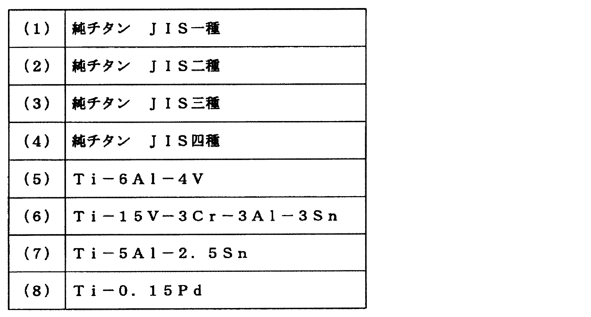
上記(1)~(8)に示す材料は、いずれも上記組成の液状体Qとの間の親和性が液状体Q同士の親和性よりも弱い、という性質を有している。より具体的には、上記(1)~(8)に示す材料は、いずれも液状体Qに含まれるヒドラジンとの間の親和性がヒドラジン同士の親和性よりも弱い、という性質を有している。このため、上記(1)~(8)に示す材料を用いて形成されたスリットノズルNZには、液状体Qが付着しにくくなる。
本実施形態では、例えばスリットノズルNZの全体が、上記材料(1)~(8)の少なくとも1種類を用いて形成されている。このため、スリットノズルNZの表面全体において、液状体Qとの間の親和性が液状体Q同士の親和性よりも弱い部分(親和性調整部)AFが形成されることになる。
このスリットノズルNZの表面全体には、例えば先端部分NZaや、前記先端部分NZaに隣接する隣接部分が含まれている。前記隣接部分としては、例えば図2A及び図2Bに示すように、スリットノズルNZの先端部分NZaの+X側端辺及び-X側端辺にそれぞれ接続された傾斜部分NZb及びNZcが挙げられる。また、隣接部分として、前記傾斜部分NZb及びNZcの+Z側にそれぞれ接続された壁部分NZd及びNZeを含めても構わない。
このように、本実施形態のスリットノズルNZは、上記材料(1)~(8)の少なくとも1種類を用いて形成されていることにより、親和性調整部AF(例えば先端部分NZa、傾斜部分NZb及びNZc、壁部分NZd及びNZeなど)を含む表面全体において、液状体Qが付着しにくくなるように構成されている。
また、上記(1)~(8)に示す材料とヒドラジンとの間の親和性は、モリブデンとヒドラジンとの間の親和性よりも弱い、という性質がある。本実施形態では、基板Sがモリブデンを用いて形成されているため、上記(1)~(8)に示す材料とヒドラジンとの間の親和性は、前記基板Sとヒドラジンとの間の親和性よりも弱い、という性質を有することになる。
換言すると、液状体Qは、上記(1)~(8)に示す材料を用いて形成されたスリットノズルNZに比べて、モリブデンを用いて形成された基板Sに対して、より付着しやすくなる。このように、スリットノズルNZは、ノズル開口部21から吐出された液状体Qが、スリットノズルNZに付着しにくくなり、かつ、基板Sに対して付着しやすくなるように形成されている。
スリットノズルNZには、ノズル駆動機構NA(図1参照)が設けられている。ノズル駆動機構NAは、スリットノズルNZをX方向、Y方向及びZ方向に駆動する構成を有している。例えば、ノズル駆動機構NAは、収容室RM1の待機位置と塗布位置(図1に示す位置)との間でスリットノズルNZを移動可能な構成を有している。
ダミー吐出機構DDは、スリットノズルNZの上記待機位置に設けられている。ダミー吐出機構DDは、例えば液状体をダミー吐出する。ダミー吐出機構には、例えば液状体の気泡を検出する不図示の気泡センサが設けられている。
収容室RM1のうち、スリットノズルNZの-Z側は、基板Sに液状体の塗布が行われる塗布空間R1となる。収容室RM1のうち、スリットノズルNZの+X側の空間は、基板Sの塗布後移動空間R2の一部となる。
(第二チャンバ装置)
図1に戻って、第二チャンバ装置CB2は、収容室RM2、基板搬入口EN2及び基板搬出口EX2を有している。収容室RM2は、内部に基板Sを収容可能に設けられている。収容室RM2は、基板Sの塗布後移動空間R2の一部となる。基板搬入口EN2及び基板搬出口EX2は、収容室RM2に形成された開口部である。基板搬入口EN2は、例えば収容室RM2の-X側端部に形成されており、第一接続室JC2に接続されている。基板搬出口EX2は、例えば収容室RM2の+X側端部に形成されており、外部に接続されている。基板搬入口EN2及び基板搬出口EX2は、基板Sが通過可能な寸法に形成されている。
図1に戻って、第二チャンバ装置CB2は、収容室RM2、基板搬入口EN2及び基板搬出口EX2を有している。収容室RM2は、内部に基板Sを収容可能に設けられている。収容室RM2は、基板Sの塗布後移動空間R2の一部となる。基板搬入口EN2及び基板搬出口EX2は、収容室RM2に形成された開口部である。基板搬入口EN2は、例えば収容室RM2の-X側端部に形成されており、第一接続室JC2に接続されている。基板搬出口EX2は、例えば収容室RM2の+X側端部に形成されており、外部に接続されている。基板搬入口EN2及び基板搬出口EX2は、基板Sが通過可能な寸法に形成されている。
基板搬入口EN2及び基板搬出口EX2には、それぞれシャッタ部材SH2が設けられている。シャッタ部材SH2を例えばZ方向にスライドさせることにより、基板搬入口EN2及び基板搬出口EX2が開閉するように構成されている。シャッタ部材SH2を閉じることにより、収容室RM2が密閉されるようになっている。
収容室RM2には、基板駆動機構SA2、加熱部HTが設けられている。また、収容室RM2には、例えば前記収容室RM2の環境を調整する環境調整部ACが接続されている。基板駆動機構SA2は、基板駆動機構SAL、SA1と同様、収容室RM2内で基板Sを搬送する部分である。
基板駆動機構SA2は、複数のローラー部材52を有している。ローラー部材52は、基板搬入口EN2から基板搬出口EX2にかけてX方向に配列されている。各ローラー部材52は、不図示のローラー回転制御部によって回転が制御されるようになっている。基板駆動機構SA2としては、上記の基板駆動機構SAL、SA1と同様に、例えばコロ搬送機構を用いても構わないし、基板を浮上させて搬送する浮上搬送機構を用いても構わない。
加熱部HTは、基板S上に塗布された液状体を加熱する部分である。加熱部HTは、内部に赤外線装置やホットプレート、オーブン機構などの加熱機構を有している。加熱部HTでは、前記加熱機構を用いることにより、例えば液状体の乾燥や、液状体の焼成などが行われるようになっている。
(環境調整部)
環境調整部ACは、酸素濃度センサ31、圧力センサ32、不活性ガス供給部33、排気部34を有している。
酸素濃度センサ31及び圧力センサ32は、第一チャンバ装置CB1の収容室RM1及び第二チャンバ装置CB2の収容室RM2にそれぞれ1つずつ設けられている。酸素濃度センサ31は、収容室RM1及び収容室RM2の酸素濃度を検出し、検出結果を制御装置CONTに送信する。圧力センサ32は、収容室RM1及び収容室RM2の圧力を検出し、検出結果を制御装置CONTに送信する。図1においては、酸素濃度センサ31及び圧力センサ32は、収容室RM1及び収容室RM2の天井部分に取り付けられた構成が示されているが、他の部分に設けられている構成であっても構わない。
環境調整部ACは、酸素濃度センサ31、圧力センサ32、不活性ガス供給部33、排気部34を有している。
酸素濃度センサ31及び圧力センサ32は、第一チャンバ装置CB1の収容室RM1及び第二チャンバ装置CB2の収容室RM2にそれぞれ1つずつ設けられている。酸素濃度センサ31は、収容室RM1及び収容室RM2の酸素濃度を検出し、検出結果を制御装置CONTに送信する。圧力センサ32は、収容室RM1及び収容室RM2の圧力を検出し、検出結果を制御装置CONTに送信する。図1においては、酸素濃度センサ31及び圧力センサ32は、収容室RM1及び収容室RM2の天井部分に取り付けられた構成が示されているが、他の部分に設けられている構成であっても構わない。
不活性ガス供給部33は、収容室RM1及び収容室RM2内に例えば窒素ガスやアルゴンガス、ヘリウムガスなどの不活性ガスを供給する。不活性ガス供給部33は、ガス供給源33a、配管33b及び供給量調整部33cを有している。ガス供給源33aは、例えばガスボンベなどを用いることができる。
配管33bは、一端がガス供給源33aに接続されており、他端が収容室RM1及び収容室RM2に分岐されて接続されている。配管33bのうち収容室RM1及び収容室RM2に接続された端部が、それぞれ収容室RM1及び収容室RM2における不活性ガス供給口となる。前記不活性ガス供給口は、例えば収容室RM1の-X側の壁部であって天井付近に配置されている。また、前記不活性ガス供給口は、例えば収容室RM2の+X側の壁部であって天井付近に配置されている。
供給量調整部33cは、収容室RM1及び収容室RM2に供給する不活性ガスの供給量を調整する部分である。供給量調整部33cとしては、例えば電磁弁や手動で開閉させるバルブなどを用いることができる。供給量調整部33cは、例えば配管33bに設けられている。供給量調整部33cについては、配管33bに配置する構成の他、例えばガス供給源33aに直接設置する構成としても構わない。
排気部34は、収容室RM1及び収容室RM2の気体を外部に排出する。また、排気部34は、収容室RM1及び収容室RM2の気体を排気して前記収容室RM1及び収容室RM2を減圧させる場合にも用いられる。排気部34は、排気駆動源34a、配管34b、配管34c及び除去部材34dを有している。排気駆動源34aは、配管34bを介して収容室RM1及び収容室RM2の内部にそれぞれ分岐されて接続されている。排気駆動源34aとしては、例えばポンプなどが用いられている。配管34bは、収容室RM1及び収容室RM2の内部に設けられる端部に排気口を有している。この排気口は、例えば収容室RM1及び収容室RM2のそれぞれの底部(-Z側の面)に配置されている。
このように、不活性ガス供給口が収容室RM1及び収容室RM2の+Z側に配置され、排気口が収容室RM1及び収容室RM2の-Z側に配置されていることにより、収容室RM1及び収容室RM2において気体が-Z方向に流通するようになっている。このため、収容室RM1及び収容室RM2では、それぞれ気体の巻き上げの発生が抑えられた状態になっている。
配管34cは、一端が排気駆動源34aに接続されており、他端が不活性ガス供給部33の配管33bに接続されている。配管34cは、排気駆動源34aによって排気された収容室RM1及び収容室RM2の気体を供給経路に循環させる循環経路となる。このように、排気部34は、収容室RM1及び収容室RM2の気体を循環させる循環機構を兼ねている。配管34cの接続先としては、不活性ガス供給部33の配管33bに限られず、例えば直接収容室RM1及び収容室RM2内にそれぞれ接続されている構成であっても構わない。配管34cには、例えば除去部材34dの上流側及び下流側にそれぞれバルブが設けられている。
除去部材34dは、配管34c内に設けられている。除去部材34dとしては、例えば配管34c内を流通する気体のうち酸素成分及び水分を吸着させる吸着剤が用いられている。このため、循環させる気体を清浄化させることができるようになっている。除去部材34dは、配管34c内の一箇所に配置させる構成であっても構わないし、配管34cの全体に亘って配置された構成であっても構わない。
(制御装置)
制御装置CONTは、塗布装置CTRを統括的に制御する部分である。具体的には、制御装置CONTは、ロードロック装置LL、第一チャンバ装置CB1、第二チャンバ装置CB2及び環境調整部ACのそれぞれの動作を制御する。例えば、シャッタ部材SHL、SH1及びSH2の開閉動作、基板駆動機構SAL、SA1及びSA2の動作、塗布部CTによる塗布動作、加熱部HTによる加熱動作、環境調整部ACによる調整動作などを制御する。
制御装置CONTは、塗布装置CTRを統括的に制御する部分である。具体的には、制御装置CONTは、ロードロック装置LL、第一チャンバ装置CB1、第二チャンバ装置CB2及び環境調整部ACのそれぞれの動作を制御する。例えば、シャッタ部材SHL、SH1及びSH2の開閉動作、基板駆動機構SAL、SA1及びSA2の動作、塗布部CTによる塗布動作、加熱部HTによる加熱動作、環境調整部ACによる調整動作などを制御する。
調整動作の一例として、制御装置CONTは、酸素濃度センサ31及び圧力センサ32による検出結果に基づいて、不活性ガス供給部33の供給量調整部33cの開度を調整する。制御装置CONTは、例えば処理時間の計測等に用いる不図示のタイマーなどを有している。
[塗布動作]
次に、本実施形態に係る塗布動作を説明する。本実施形態では、上記のように構成された塗布装置CTRを用いて基板S上に塗布膜を形成する。塗布装置CTRの各部で行われる動作は、制御装置CONTによって制御される。
次に、本実施形態に係る塗布動作を説明する。本実施形態では、上記のように構成された塗布装置CTRを用いて基板S上に塗布膜を形成する。塗布装置CTRの各部で行われる動作は、制御装置CONTによって制御される。
制御装置CONTは、塗布装置CTRに設けられるシャッタ部材SHL、SH1及びSH2を閉じた状態にしておく。この状態で、外部から塗布装置CTRに基板Sが搬送されてきたら、制御装置CONTは、ロードロック装置LLの基板搬入口ENLに設けられるシャッタ部材SHLを開いた状態として、前記基板搬入口ENLから基板Sを収容室RMLに搬入させる。
図3に示すように、基板Sを収容室RMLに搬入させた後、制御装置CONTは、基板搬入口ENLのシャッタ部材SHLを閉じた状態とし、収容室RMLを密閉状態とする。
制御装置CONTは、収容室RMLを密閉状態とした後、減圧機構DCLを用いて収容室RMLを減圧状態とする。
制御装置CONTは、収容室RMLを密閉状態とした後、減圧機構DCLを用いて収容室RMLを減圧状態とする。
制御装置CONTは、第一チャンバ装置CB1の収容室RM1及び第二チャンバ装置CB2の収容室RM2が密閉状態になっていることを確認した後、前記収容室RM1及びRM2の雰囲気を不活性ガス雰囲気に調整させる。具体的には、不活性ガス供給部33を用いて収容室RM1及び収容室RM2に不活性ガスを供給させる。この場合、制御装置CONTは、適宜排気部34を作動させることによって収容室RM1及びRM2の圧力を調整させるようにしても構わない。
加えて、制御装置CONTは、スリットノズルNZの保持部に液状体を保持させる。制御装置CONTは、スリットノズルNZ内の温調機構を用いて、保持部に保持された液状体の温度を調整させる。このように、制御装置CONTは、基板Sに液状体を吐出させる状態を整えておく。
塗布装置CTRの状態が整ったら、制御装置CONTは、図4に示すように、ロードロック装置LLの基板搬出口EXL及び第一チャンバ装置CB1の基板搬入口EN1を開いた状態とし、ロードロック装置LLから第一接続室JC1を介して第一チャンバ装置CB1の収容室RM1に基板Sを搬入させる。
基板Sの搬入後、制御装置CONTは、基板駆動機構SA1のローラー部材51を回転させ、基板Sを+X方向に移動させる。基板Sの+X側の端辺がZ方向視でスリットノズルNZのノズル開口部21に重なる位置に到達したら、図5に示すように、制御装置CONTはスリットノズルNZを用いて基板Sに液状体Qを塗布させる。
この場合、制御装置CONTは、スリットノズルNZと基板Sとを相対移動させて(本実施形態では基板Sを+X方向に移動させて)スリットノズルNZの先端部分NZaを基板Sに対向させる。先端部分NZaと基板Sとを対向させた後、制御装置CONTは、図5に示すように、先端部分NZaと基板Sとの間で液状体が挟持されるようにノズル開口部21から液状体Qを吐出させる。
ここで、先端部分NZaにおける液状体Qとの親和性が、液状体Q同士の親和性よりも強い場合、液状体Qは、液状体Q同士で接触するよりも先端部分NZaに接触しようとする。このため、液状体Qが先端部分NZaに付着した状態となってしまい、基板Sに対する定着性が低下してしまう。また、先端部分NZaのみならず、隣接部分である傾斜部分NZb、NZcにおける液状体Qとの親和性が、液状体Q同士の親和性よりも強い場合、液状体Qは先端部分NZaから傾斜部分NZb、NZcへと伝わってしまい、さらに基板Sへの定着性が低下してしまう。更に、先端部分NZa(及び隣接部分)における液状体Qとの親和性が液状体Qと基板Sとの親和性よりも強い場合、液状体Qは基板Sよりも先端部分NZa(及び隣接部分)に付着しようとするため、この場合も基板Sへの定着性が低下してしまう。
これに対して、本実施形態においては、スリットノズルNZは、全体が上記の表1の(1)~(8)に示す材料のうち少なくとも1種類を用いて形成されているため、例えばスリットノズルNZの先端部分NZa(親和性調整部AF)における液状体Qとの親和性は、液状体Q同士の親和性よりも弱くなっている。また、前記先端部分NZaにおける液状体Qとの親和性は、基板Sと液状体Qとの間の親和性よりも弱くなっている。
したがって、上記のようにスリットノズルNZの先端部分NZaと基板Sとで液状体Qを挟むことにより、液状体Qが先端部分NZaに付着しにくい状態になると共に、液状体Q同士で接触しやすい状態となる。また、液状体Qは先端部分NZaよりも基板Sに付着しやすい状態になる。
制御装置CONTは、このような状態において、ノズル開口部21から液状体Qを吐出させつつ基板Sを移動させる。この動作により、液状体Qは先端部分NZaから傾斜部分NZbや傾斜部分NZcなどに流れてしまうことなく、基板S上に配置されて定着することになる。
また、基板Sに配置された液状体Q同士の親和性により、基板Sがノズル開口部21から遠ざかると、基板S上に塗布された液状体Qが先端部分NZaの液状体Qを引っ張るように作用する。このような結果、図6に示すように、基板Sの所定領域上に前記液状体の塗布膜Lがほぼ均一の膜厚で形成される。塗布膜Lの形成後、制御装置CONTは、ノズル開口部21からの液状体の吐出動作を停止させる。
吐出動作を停止後、制御装置CONTは、塗布膜Lが形成された基板Sを第二チャンバ装置CB2の収容室RM2に収容させる。具体的には、図7に示すように、制御装置CONTは、収容室RM1の基板搬出口EX1及び収容室RM2の基板搬入口EN2を開いた状態とし、基板搬出口EX1、第二接続室JC2及び基板搬入口EN2を介して前記基板Sを収容室RM2へと搬入させる。
制御装置CONTは、基板Sを収容室RM2に搬入した後、図8に示すように、前記基板Sが加熱部HTの-Z側に位置するように移動させ、その後排気部34を作動させることにより収容室RM2を減圧させる。収容室RM2を減圧させた後、制御装置CONTは、加熱部HTを作動させて基板S上の塗布膜Lを加熱させる。減圧下で液状体を加熱することにより、塗布膜Lは短時間で効率的に乾燥する。
この乾燥動作においては、収容室RM2を減圧させない状態で加熱処理だけで行っても構わない。また、この乾燥動作においては、加熱させない状態で収容室RM2の減圧処理のみで行っても構わない。さらに減圧処理を行った後に加熱処理を行っても構わない。
加熱ステップでの加熱温度は、例えば300℃以下となるようにする。また、例えば、50℃以上となるようにする。加熱温度を300℃以下とすることにより、基板Sの構成材料が樹脂材料であっても、基板Sに変形させること無く加熱処理が行われることとなる。このため、基板Sの材料の選択の幅が広がることとなる。
制御装置CONTは、例えばローラー部材52の回転動作を停止させ、基板Sの移動を停止させた状態で加熱部HTを作動させるようにする。例えば基板S上の塗布膜Lが乾燥するまでの時間や加熱温度などを予め記憶させておくようにし、制御装置CONTが前記記憶させた値を用いて加熱時間及び加熱温度などを調整することで塗布膜Lの加熱動作を行わせる。
また、ローラー部材52の回転動作をさせたまま加熱部HT下を基板Sが通過してもよい。その際、加熱部HTはそのXマイナス方向からXプラス方向へと温度勾配を持つようにしてもよい。その場合基板Sは徐々に加熱され、所望の温度で設定時間加熱処理された後、徐々に除冷されるため、基板Sや基板S上に塗布された易酸化性の金属を含有する膜にストレスを与えずに乾燥させることができる。
上記易酸化性の金属を含有する液状体Qを基板S上に塗布して光吸収層の一部を形成する場合、例えばCuやInなどは酸化しやすい性質を有する(易酸化性)金属であるため、収容室RM1、収容室RM2における酸素濃度が高いと、易酸化性の金属が酸化してしまう。これらの金属が酸化してしまうと、基板S上に形成される塗布膜の膜質が低下してしまう虞がある。
そこで、制御装置CONTは、環境調整部ACを用いて収容室RM1及び収容室RM2が不活性ガス雰囲気下となるように調整させるようにしている。具体的には、制御装置CONTは、不活性ガス供給部33を用いることにより、収容室RM1及び収容室RM2に窒素ガスやアルゴンガスなどの不活性ガスを供給する。
供給ステップでは、制御装置CONTは、まず酸素濃度センサ31によって収容室RM1及び収容室RM2の酸素濃度を検出させる。制御装置CONTは、検出ステップでの検出結果に基づき、供給量調整部33cを用いて不活性ガスの供給量を調整させつつ、収容室RM1及び収容室RM2に不活性ガスを供給させる。例えば、検出された酸素濃度が予め設定された閾値を超えた場合に収容室RM1及び収容室RM2に不活性ガスを供給させることができる。前記閾値については、予め実験やシミュレーションなどによって求めておき、制御装置CONTに記憶させておくことができる。また、例えば、塗布動作及び乾燥動作の間、常時一定量の不活性ガスを収容室RM1及び収容室RM2に供給させた状態にしておき、酸素濃度センサ31の検出結果に基づいて、供給量を多くしたり少なくしたりさせることもできる。
供給ステップでは、制御装置CONTは、酸素濃度センサ31を用いると同時に、圧力センサ32によって収容室RM1及び収容室RM2の気圧を検出させる。制御装置CONTは、圧力センサ32の検出結果に基づき、供給量調整部33cを用いて不活性ガスの供給量を調整しつつ、収容室RM1及び収容室RM2に不活性ガスを供給させる。例えば、収容室RM1及び収容室RM2の気圧が予め設定された閾値を超えた場合に、排気部34を用いて収容室RM1及び収容室RM2を排気させる。この閾値についても、予め実験やシミュレーションなどによって求めておき、制御装置CONTに記憶させておくことができる。また、例えば、塗布動作及び乾燥動作の間、収容室RM1及び収容室RM2を常時一定量排気させた状態にしておき、圧力センサ32の検出結果に基づいて、排気量を多くしたり少なくしたりさせることもできる。このようにして、収容室RM1及び収容室RM2が減圧下に保持されることになる。
排気部34から排気された気体は、配管34b及び配管34cを流通して不活性ガス供給部33の配管33bに循環される。配管34cを流通する際、この気体は除去部材34dを通過する。気体が除去部材34dを通過する際、気体中の酸素成分が除去部材34dに吸着されて除去される。このため、酸素濃度が低い状態の不活性ガスが配管33bに循環されることになる。収容室RM1及び収容室RM2の気体を循環させることにより、温度などが安定化された状態で不活性ガスが供給されることになる。
以上のように、本実施形態によれば、スリットノズルNZのうち少なくとも先端部分NZaには、液状体Qとの間の親和性が液状体Q同士の親和性よりも弱くなるように形成された親和性調整部AFが設けられているため、スリットノズルNZの先端部分NZaから吐出された液状体Qが前記先端部分NZaに付着するのを抑制することができる。これにより、液状体Qが基板Sに定着しやすくなるため、基板Sに液状体Qをムラ無く塗布することが可能となる。
本発明の技術範囲は上記実施形態に限定されるものではなく、本発明の趣旨を逸脱しない範囲で適宜変更を加えることができる。
例えば、上記実施形態では、スリットノズルNZの全体が表1に示す(1)~(8)の少なくとも1種類の材料を用いて構成された例を示したが、これに限られることは無い。
例えば、上記実施形態では、スリットノズルNZの全体が表1に示す(1)~(8)の少なくとも1種類の材料を用いて構成された例を示したが、これに限られることは無い。
例えば図9に示すように、スリットノズルNZの先端部分NZa、傾斜部分NZb及びNZc、壁部分NZd及びNZeをそれぞれ覆うように形成された被覆部NZfを有する構成であっても構わない。前記被覆部NZfは、上記(1)~(8)の少なくとも1種類の材料を用いて形成されている。例えばスリットノズルNZの表面をコーティング処理したり、蒸着処理したりすることにより、上記構成の被覆部NZfを形成することができる。スリットノズルNZの表面に被覆部NZfが設けられた場合であっても、前記被覆部NZfが設けられた部分に親和性調整部AFが形成されることになる。この場合、スリットノズルNZのうち被覆部NZf以外の部分は、上記(1)~(8)の材料とは異なる材料であっても構わない。
また、上記実施形態では、塗布部CTと加熱部HTとを別々のチャンバ装置(第一チャンバ装置CB1及び第二チャンバ装置CB2)に配置させた構成としたが、これに限られることは無く、1つのチャンバ装置CBに配置させる構成であっても構わない。例えば図10に示すように、1つのチャンバ装置CB内の同一の空間に塗布部CTと加熱部HTとを配置させるようにしても構わない。この場合、塗布部CTの-Z側の空間が塗布空間R1となり、前記塗布空間の+X側の空間が塗布後移動空間R2となる。
また、図11に示すように、スリットノズルNZと加熱部HTとが異なる空間に配置されるようにチャンバCB内の空間が2つに仕切られた構成としても構わない。チャンバCB内には、仕切り部材110が設けられている。仕切り部材110は、基板Sの搬送方向上に配置されている。基板Sは、仕切り部材110を超えて搬送されることになる。
仕切り部材110のうち基板Sの高さ位置(Z方向上の位置)に対応する領域には、開口部111が形成されている。開口部111には、蓋部111aが設けられており、開口部111が開閉可能になっている。基板Sを搬送する場合、基板Sが仕切り部材110を通過する際には蓋部111aをそれぞれ開状態として前記基板Sを通過させる。基板Sが通過しないときや、各空間内で処理を行う場合には蓋部111aを閉状態とする。
チャンバCB内の酸素濃度を検出する酸素濃度センサ31や圧力を検出する圧力センサ32は、仕切り部材110で区切られた各空間にそれぞれ設けられている。また、環境調整部についても、2つの空間にそれぞれ接続されている。スリットノズルNZが配置される空間には、環境調整部AC1が接続されている。環境調整部AC1の構成は、第1実施形態における環境調整部ACの構成と同一構成となっている。
加熱部HTが設けられる空間には、環境調整部AC2が接続されている。環境調整部AC2には、環境調整部AC1(又は第1実施形態に記載の環境調整部AC)の構成に加えて、配管34cから分岐する分岐配管125が設けられている。したがって、配管34cと同様、分岐配管125にも排気駆動源34aによって排気された気体が流通するようになっている。
分岐配管125は、例えば蓄熱機構120に接続されている。分岐配管125上には、前記分岐配管125を流通する気体を加熱する加熱機構121が設けられている。また、分岐配管125には酸素を除去する除去部材(例えば第1実施形態の除去部材34dと同一の部材)が設けられた構成であっても構わない。
加熱部HTは、蓄熱機構120とホットプレート130とを有している。蓄熱機構120は基板Sの搬送領域に対してチャンバCBの天井側に配置されており、ホットプレート130は基板Sの搬送領域に対してチャンバCBの底部側に配置されている。ホットプレート130には、第1実施形態の加熱部HTと同様に不図示の加熱機構が設けられている。
蓄熱機構120は、チャンバCB内の気体の熱を蓄熱できるようになっている。また、蓄熱機構120には、分岐配管125を流通する気体が供給されるようになっている。このため、蓄熱機構120では、供給された気体の熱がチャンバCB内の温度とほぼ同一の温度に温調されるようになっている。蓄熱機構120は、-Z側に開口部を有しており、分岐配管125からの気体が開口部を介してチャンバCB内に流入されるようになっている。
上記構成においては、スリットノズルNZと加熱部HTとが異なる空間に設けられていることになるため、塗布ステップ及び加熱ステップは1つのチャンバCBの異なる空間で行われることになる。この場合、制御装置CONTは、まずスリットノズルNZが配置された空間において基板Sに塗布ステップを行わせる。塗布ステップが完了した後、制御装置CONTは、蓋部111aを開状態として基板Sを加熱部HTが配置された空間に搬送させる。
基板Sの搬送後、制御装置CONTは、蓋部111aを閉状態として前記加熱部HTが配置された空間を減圧させる。減圧後、制御装置CONTは、加熱部HTを作動させて基板S上の液状体に加熱ステップを行う。加熱ステップでは、基板Sは蓄熱機構120とホットプレート130とによって表裏の両側から加熱されることになる。加熱ステップにおいて、前記空間から排気された気体(例えば不活性ガス)は分岐配管125を介して蓄熱機構120に供給される。蓄熱機構120に供給された気体は、蓄熱された熱によって加熱され、空間内とほぼ同一の温度に温調されることになる(気体加熱ステップ)。この気体は、蓄熱機構120の開口部から空間内に供給され、再利用されることとなる。気体加熱ステップでは、分岐配管125に設けられた加熱機構121を用いて気体を加熱しても構わない。
加熱ステップの終了後、制御装置CONTは、加熱部HTの動作を停止させると共にチャンバCB内(空間内)の圧力を大気圧に戻させる。その後、制御装置CONTは、蓋部111aを閉状態としたまま蓋部12aを開状態とし、基板Sを+X方向に搬送させて前記基板Sを搬出させる。
また、上記実施形態では、塗布動作を行う際、スリットノズルNZを固定させた状態で基板Sを移動させることで液状体Qを基板S上に塗布する例を挙げて説明したが、これに限られることは無く、基板Sを固定させた状態でスリットノズルNZを移動させることで液状体Qを基板S上に塗布するようにしても構わない。また、基板SとスリットノズルNZとを両方移動させるようにしても構わない。
また、上記実施形態では、基板S上に易酸化性の金属を含む塗布膜を形成する例を挙げて説明したが、これに限られることは無い。例えば、図12に示すように、帯状の連続したフィルム上に液状体Qを塗布するようにしても構わない。図12は、塗布装置CTRの他の構成を示す図である。図12に示すように、塗布装置CTRは、基板搬入チャンバSLC、基板処理チャンバSPC、基板搬出チャンバSUC及びこれらを制御する制御装置CONTを有している。
基板搬入チャンバSLCは、帯状に形成されたフィルム基板Fを収容する収容室RMAを有している。収容室RMAには、フィルム基板Fが巻きつけられる軸部SF1が設けられている。軸部SF1は、Y方向に延在するように配置されており、θY方向に回転可能に設けられている。収容室RMAは、不活性ガス供給部133及び排気部134に接続されている。収容室RMAには、フィルム基板Fを搬送する基板搬送機構FALが設けられている。基板搬送機構FALとしては、例えばローラー機構などを用いることができる。
基板処理チャンバSPCは、収容室RMBを有している。収容室RMBは、開口部OP1を介して基板搬入チャンバSLCの収容室RMAに接続されている。収容室RMBには、塗布部CT、基板搬送部FAP、加熱部HT、ノズル先端管理部MN、搬入側シャッタ部SH1及び搬出側シャッタ部SH2が設けられている。収容室RMBは、不活性ガス供給部133及び排気部134に接続されている。
塗布部CTは、ノズルNZ及びノズル駆動機構NAを有している。ノズルNZは、例えば-Z側の端部が先細りに形成されている。ノズルNZは、-Z側の端部(先端)から液状体を吐出可能に設けられている。ノズル駆動機構NAは、必要に応じてノズルNZをX方向、Y方向及びZ方向などに駆動する。
基板搬送部FAPは、ノズルNZの-Z側にフィルム基板Fを搬送するように構成されている。基板搬送部FAPは、複数のローラー部を有している。前記ローラー部の配置を組み合わせることにより、ノズルNZの-Z側を通過するようにフィルム基板Fの搬送経路が設定されている。
加熱部HTは、フィルム基板FをZ方向に挟むように、前記フィルム基板Fの搬送経路の+Z側及び-Z側に1つずつ配置されている。加熱部HTとしては、例えば上記実施形態の構成と同一の加熱部HTが用いられる。加熱部HTをフィルム基板Fの+Z側及び-Z側に配置させることにより、乾燥工程及び加熱工程を効率的に行うことができるようになっている。
ノズル先端管理部MNは、ノズルNZの先端をメンテナンスする。ノズル先端管理部MNは、例えばノズルNZの移動可能な範囲内に配置されており、ノズルNZの先端の洗浄を行う部分、ノズルNZの予備吐出を行う部分、ノズルNZの先端を乾燥させる部分、などが設けられている。
搬入側シャッタ部SH1は、基板搬入チャンバSLCの収容室RMAと、基板処理チャンバSPCの収容室RMBとの間を開閉させる開閉機構である。搬入側シャッタ部SH1は、不図示の駆動機構などによってZ方向に移動可能に設けられている。図12には、搬入側シャッタ部SH1が開状態になっている様子が示されている。
搬出側シャッタ部SH2は、収容室RMBと基板搬出チャンバSUCの収容室RMCとの間を開閉させる開閉機構である。搬出側シャッタ部SH2は、不図示の駆動機構などによってZ方向に移動可能に設けられている。図12には、搬出側シャッタ部SH2が開状態になっている様子が示されている。
基板搬出チャンバSUCは、フィルム基板Fを収容する収容室RMCを有している。収容室RMCは、開口部OP2を介して基板処理チャンバSPCの収容室RMBに接続されている。収容室RMCには、フィルム基板Fを巻き取る軸部SF2が設けられている。軸部SF2は、Y方向に延在するように配置されており、θY方向に回転可能に設けられている。収容室RMCは、不活性ガス供給部133及び排気部134に接続されている。収容室RMCには、フィルム基板Fを搬送する基板搬送機構FAUが設けられている。基板搬送機構FAUとしては、例えばローラー機構などを用いることができる。
次に、上記構成の塗布装置CTRの動作を説明する。
初期状態では、軸部SF1にフィルム基板Fが巻きつけられている。制御装置CONTは、搬入側シャッタ部SH1及び搬出側シャッタ部SH2を開いた状態とした後、不活性ガス供給部133による供給量及び排気部134による排気量を適宜調整し、収容室RMA、収容室RMB及び収容室RMCの環境を調整する。
初期状態では、軸部SF1にフィルム基板Fが巻きつけられている。制御装置CONTは、搬入側シャッタ部SH1及び搬出側シャッタ部SH2を開いた状態とした後、不活性ガス供給部133による供給量及び排気部134による排気量を適宜調整し、収容室RMA、収容室RMB及び収容室RMCの環境を調整する。
制御装置CONTは、その後、軸部SF1を+θY方向に回転させてフィルム基板Fを+X側へ搬送する。フィルム基板Fは開口部OP1を介して収容室RMAから収容室RMBへと搬送される。制御装置CONTは、収容室RMB内の基板搬送機構FAPを構成するローラー部を回転させることにより、フィルム基板Fを+X側へ搬送させる。
フィルム基板FがノズルNZの-Z側へ搬送された場合には、制御装置CONTはノズルNZから液状体を一定時間フィルム基板Fへ向けて吐出させる。この動作により、フィルム基板Fの所定領域に液状体Qが塗布される。この動作を繰り返し行うことにより、ノズルNZの-Z側を連続的に通過するフィルム基板Fに対して所定領域毎に液状体Qの塗布膜を形成することができる。
フィルム基板Fを搬送させることにより、液状体Qが塗布された部分が2つの加熱部HTに挟まれた空間に到達する。このとき、制御装置CONTは、2つの加熱部HTのうち少なくとも一方を作動させることにより、フィルム基板F上に塗布された液状体Qに対して乾燥処理あるいは加熱処理が施されることになる。
制御装置CONTは、フィルム基板Fのうち乾燥処理あるいは加熱処理が終了した部分を、開口部OP2を介して基板搬出チャンバSUCの収容室RMCに搬出する。フィルム基板Fの先端が収容室RMCの軸部SF2に到達した場合、制御装置CONTは、軸部SF2を回転させ、前記軸部SF2にフィルム基板Fを巻き取らせる。全てのフィルム基板Fが軸部SF2に巻き取られた後、制御装置CONTは、搬入側シャッタ部SH1及び搬出側シャッタ部SH2を閉じた状態とする。
搬入側シャッタ部SH1及び搬出側シャッタ部SH2が閉状態となった場合、収容室RMAと収容室RMBとの間、収容室RMBと収容室RMCとの間は、それぞれ遮断されることになる。このため、例えば収容室RMAに収容されるフィルム基板Fが全て基板処理チャンバSPCへ搬入された後、搬入側シャッタ部SH1を閉状態として軸部SF1を交換する。同様に、例えば収容室RMCにフィルム基板Fが全て巻き取られた後、搬出側シャッタ部SH2を閉状態として軸部SH2を交換する。以上のように、帯状の連続したフィルム上に液状体Qを塗布する場合であっても、本発明の適用は可能である。
本発明によれば、基板上に液状体をムラ無く塗布することが可能となるため、産業上極めて有用である。
CTR…塗布装置 LL…ロードロック装置 CB1…第一チャンバ装置 CB2…第二チャンバ装置 RML、RM1、RM2…収容室 SAL、SA1、SA2…基板駆動機構 CT…塗布部 NZ…スリットノズル NZa…先端部分 Q…液状体 AF…親和性調整部 NA…ノズル駆動機構 R1…塗布空間 R2…塗布後移動空間 HT…加熱部 CONT…制御装置 21…ノズル開口部 S…基板
Claims (12)
- 先端部分に設けられた吐出部から易酸化性の金属を含む液状体を吐出するノズルを有する塗布部と、
前記先端部分と基板とを対向させた状態で前記基板と前記ノズルとを相対移動させる相対駆動部と
を備え、
前記ノズルのうち少なくとも前記先端部分には、前記液状体との間の親和性が前記液状体同士の親和性よりも弱くなるように形成された親和性調整部が設けられている
塗布装置。 - 前記親和性調整部は、前記ノズルのうち、前記先端部分と、前記先端部分に隣接する部分と、を含む部分に設けられている
請求項1に記載の塗布装置。 - 前記液状体は、ヒドラジンを含み、
前記親和性調整部は、前記ヒドラジンとの間の親和性が前記ヒドラジン同士の親和性よりも弱くなるように形成されている
請求項1に記載の塗布装置。 - 前記親和性調整部は、前記ヒドラジンとの間の親和性が前記ヒドラジンと前記基板との間の親和性よりも弱くなるように形成されている
請求項3に記載の塗布装置。 - 前記親和性調整部は、チタン及びチタン合金のうち少なくとも一方を用いて形成されている
請求項1に記載の塗布装置。 - 前記基板は、モリブデンを用いて形成されている
請求項1に記載の塗布装置。 - 前記金属は、銅、インジウム、ガリウム及びセレンのうち少なくとも1つを含む
ことを特徴とする請求項1に記載の塗布装置。 - 前記塗布部によって前記液状体の塗布される塗布空間及び前記液状体の塗布された前記基板の塗布後移動空間のうち少なくとも一方の空間を囲むチャンバ
を更に備える請求項1に記載の塗布装置。 - 前記チャンバで囲まれた前記空間に不活性ガスを供給する不活性ガス供給部を更に備える
請求項8に記載の塗布装置。 - 前記塗布部における吐出部は、前記先端部分に対向する吐出領域に前記液状体を吐出するように形成されており、
前記相対駆動部は、前記吐出領域を通過するように前記基板を搬送する基板搬送部を有する
請求項1に記載の塗布装置。 - 前記塗布部における吐出部は、前記先端部分に対向する吐出領域に前記液状体を吐出するように形成されており、
前記相対駆動部は、前記吐出領域が前記基板上を走査するように前記ノズルを駆動するノズル駆動部を有する
請求項1に記載の塗布装置。 - 易酸化性の金属を含む液状体を基板に塗布する塗布方法であって、
前記液状体との間の親和性が前記液状体同士の親和性よりも弱くなるように形成された親和性調整部が設けられる先端部分に形成された吐出部から前記液状体を吐出するノズルを有する塗布部の前記先端部分を前記基板に対向させるステップと、
前記先端部分と前記基板との間で前記液状体が挟持されるように、前記吐出部から前記液状体を吐出するステップと、
前記先端部分と前記基板との間で前記液状体を挟持した状態で、前記吐出部から前記液状体を吐出しつつ前記先端部分と前記基板とを相対移動させるステップと
を含む塗布方法。
Priority Applications (1)
| Application Number | Priority Date | Filing Date | Title |
|---|---|---|---|
| US13/878,964 US9299874B2 (en) | 2010-10-13 | 2011-10-12 | Coating apparatus and coating method |
Applications Claiming Priority (2)
| Application Number | Priority Date | Filing Date | Title |
|---|---|---|---|
| JP2010-230573 | 2010-10-13 | ||
| JP2010230573A JP2012081428A (ja) | 2010-10-13 | 2010-10-13 | 塗布装置及び塗布方法 |
Publications (1)
| Publication Number | Publication Date |
|---|---|
| WO2012050111A1 true WO2012050111A1 (ja) | 2012-04-19 |
Family
ID=45938340
Family Applications (1)
| Application Number | Title | Priority Date | Filing Date |
|---|---|---|---|
| PCT/JP2011/073392 Ceased WO2012050111A1 (ja) | 2010-10-13 | 2011-10-12 | 塗布装置及び塗布方法 |
Country Status (4)
| Country | Link |
|---|---|
| US (1) | US9299874B2 (ja) |
| JP (1) | JP2012081428A (ja) |
| TW (1) | TWI587928B (ja) |
| WO (1) | WO2012050111A1 (ja) |
Families Citing this family (9)
| Publication number | Priority date | Publication date | Assignee | Title |
|---|---|---|---|---|
| US20140363903A1 (en) * | 2013-06-10 | 2014-12-11 | Tokyo Ohta Kogyo Co., Ltd. | Substrate treating apparatus and method of treating substrate |
| JP6240440B2 (ja) * | 2013-08-30 | 2017-11-29 | 東京応化工業株式会社 | チャンバー装置及び加熱方法 |
| JP2015131279A (ja) * | 2014-01-15 | 2015-07-23 | 東京応化工業株式会社 | 塗布装置及び塗布方法 |
| CN104353584A (zh) * | 2014-11-19 | 2015-02-18 | 京东方科技集团股份有限公司 | 一种涂布装置及涂布方法 |
| CN104681471B (zh) * | 2015-03-12 | 2017-09-15 | 京东方科技集团股份有限公司 | 湿法刻蚀设备 |
| CN110998869B (zh) * | 2017-08-09 | 2022-12-27 | 株式会社钟化 | 光电转换元件的制造方法 |
| US20220112594A1 (en) * | 2020-10-14 | 2022-04-14 | Applied Materials, Inc. | Device for sealing a vacuum chamber, vacuum processing system, and method of monitoring a load lock seal |
| JP7531776B2 (ja) * | 2021-10-29 | 2024-08-13 | 株式会社エイ・エム・ケイ | 減圧チャンバー及びこの減圧チャンバーを用いたワークの移送方法 |
| JP2023135868A (ja) * | 2022-03-16 | 2023-09-29 | 株式会社リコー | 液体付与装置、電極製造装置、積層セパレータ製造装置、電気化学素子製造装置、液体付与方法、電極製造方法、積層セパレータ製造方法、および電気化学素子製造方法 |
Citations (4)
| Publication number | Priority date | Publication date | Assignee | Title |
|---|---|---|---|---|
| JP2000140739A (ja) * | 1998-11-10 | 2000-05-23 | Canon Inc | 枚葉塗工装置、及び該装置を用いた塗工方法とカラーフィルタの製造方法 |
| JP2005052820A (ja) * | 2003-07-02 | 2005-03-03 | Mitsubishi Materials Corp | 塗布工具および塗布装置 |
| JP2010129660A (ja) * | 2008-11-26 | 2010-06-10 | Kyocera Corp | 化合物半導体薄膜の製法および薄膜太陽電池の製法 |
| JP2011078964A (ja) * | 2009-09-08 | 2011-04-21 | Tokyo Ohka Kogyo Co Ltd | 塗布装置及び塗布方法 |
Family Cites Families (18)
| Publication number | Priority date | Publication date | Assignee | Title |
|---|---|---|---|---|
| EP0318315B1 (en) | 1987-11-27 | 1994-02-02 | Siemens Solar Industries L.P. | Process for making thin film solar cell |
| JP3791018B2 (ja) * | 1994-12-26 | 2006-06-28 | 東レ株式会社 | スリットダイコータ口金およびそれを用いた塗膜の製造方法 |
| JPH10158020A (ja) * | 1996-11-25 | 1998-06-16 | Fuji Photo Optical Co Ltd | ガラス射出成形用ノズル |
| JPH11273783A (ja) | 1998-03-20 | 1999-10-08 | Yazaki Corp | コネクタと電気機器との取付構造及び該コネクタと電気機器との取付方法 |
| JP4177480B2 (ja) | 1998-05-15 | 2008-11-05 | インターナショナル ソーラー エレクトリック テクノロジー,インコーポレイテッド | 化合物半導体フィルムおよび関連電子装置の製造方法 |
| JP2000189877A (ja) * | 1998-12-25 | 2000-07-11 | Canon Inc | スリットダイコ―タ口金およびそれを用いた塗膜製造方法 |
| JP2001056346A (ja) * | 1999-08-19 | 2001-02-27 | Fujitsu Ltd | プローブカード及び複数の半導体装置が形成されたウエハの試験方法 |
| JP2003266001A (ja) * | 2002-03-15 | 2003-09-24 | Seiko Epson Corp | 成膜装置、デバイスの製造方法及び電子機器 |
| JP2004216298A (ja) * | 2003-01-16 | 2004-08-05 | Mitsubishi Chemicals Corp | 塗布方法およびスリットダイノズル |
| US6875661B2 (en) | 2003-07-10 | 2005-04-05 | International Business Machines Corporation | Solution deposition of chalcogenide films |
| KR101257120B1 (ko) * | 2005-01-28 | 2013-04-22 | 가부시끼가이샤 이테크 | Ic 카드 제조용 접착제, ic 카드의 제조 방법 및 ic카드 |
| JP4977971B2 (ja) * | 2005-06-30 | 2012-07-18 | 大日本印刷株式会社 | カラーフィルタ用感光性樹脂組成物およびカラーフィルタの製造方法 |
| JP4674904B2 (ja) * | 2006-03-03 | 2011-04-20 | 東京エレクトロン株式会社 | 基板処理装置及び基板処理方法 |
| JP2007260639A (ja) * | 2006-03-30 | 2007-10-11 | Institute Of National Colleges Of Technology Japan | スリットコータノズル |
| CN101522954B (zh) | 2006-05-24 | 2011-11-16 | 埃托特克德国有限公司 | 金属电镀组合物和用于沉积适合于生产薄膜太阳能电池的铜-锌-锡的方法 |
| JP4361572B2 (ja) * | 2007-02-28 | 2009-11-11 | 株式会社新川 | ボンディング装置及び方法 |
| DE102008032571A1 (de) * | 2008-07-11 | 2010-01-14 | Tesa Se | Haftklebemassen und Verfahren zu deren Herstellung |
| US8551609B2 (en) * | 2010-04-27 | 2013-10-08 | Ppg Industries Ohio, Inc. | Method of depositing niobium doped titania film on a substrate and the coated substrate made thereby |
-
2010
- 2010-10-13 JP JP2010230573A patent/JP2012081428A/ja active Pending
-
2011
- 2011-10-07 TW TW100136481A patent/TWI587928B/zh not_active IP Right Cessation
- 2011-10-12 WO PCT/JP2011/073392 patent/WO2012050111A1/ja not_active Ceased
- 2011-10-12 US US13/878,964 patent/US9299874B2/en not_active Expired - Fee Related
Patent Citations (4)
| Publication number | Priority date | Publication date | Assignee | Title |
|---|---|---|---|---|
| JP2000140739A (ja) * | 1998-11-10 | 2000-05-23 | Canon Inc | 枚葉塗工装置、及び該装置を用いた塗工方法とカラーフィルタの製造方法 |
| JP2005052820A (ja) * | 2003-07-02 | 2005-03-03 | Mitsubishi Materials Corp | 塗布工具および塗布装置 |
| JP2010129660A (ja) * | 2008-11-26 | 2010-06-10 | Kyocera Corp | 化合物半導体薄膜の製法および薄膜太陽電池の製法 |
| JP2011078964A (ja) * | 2009-09-08 | 2011-04-21 | Tokyo Ohka Kogyo Co Ltd | 塗布装置及び塗布方法 |
Also Published As
| Publication number | Publication date |
|---|---|
| US9299874B2 (en) | 2016-03-29 |
| TWI587928B (zh) | 2017-06-21 |
| JP2012081428A (ja) | 2012-04-26 |
| TW201233457A (en) | 2012-08-16 |
| US20130280844A1 (en) | 2013-10-24 |
Similar Documents
| Publication | Publication Date | Title |
|---|---|---|
| WO2012050111A1 (ja) | 塗布装置及び塗布方法 | |
| JP5639816B2 (ja) | 塗布方法及び塗布装置 | |
| JP5469966B2 (ja) | 塗布装置及び塗布方法 | |
| JP5462558B2 (ja) | 塗布装置及び塗布方法 | |
| JP5719546B2 (ja) | 塗布装置及び塗布方法 | |
| JP5439097B2 (ja) | 塗布装置及び塗布方法 | |
| JP2022050623A (ja) | 半導体システムにおける湿度制御 | |
| JP2012170846A (ja) | 塗布装置 | |
| US8246284B2 (en) | Stacked load-lock apparatus and method for high throughput solar cell manufacturing | |
| US20120304921A1 (en) | Heating apparatus, coating apparatus and heating method | |
| JP6349110B2 (ja) | チャンバー装置及び加熱方法 | |
| US20130269602A1 (en) | Transporting apparatus and coating apparatus | |
| WO2010035385A1 (ja) | 真空処理装置及び真空搬送装置 | |
| US20130309408A1 (en) | Coating apparatus and coating method | |
| US20120309179A1 (en) | Substrate treating apparatus and method of treating substrate | |
| US20140370451A1 (en) | Heating apparatus and heating method | |
| TWI641157B (zh) | 室裝置及加熱方法 | |
| US20130269604A1 (en) | Nozzle and coating apparatus | |
| JP2014014816A (ja) | 基板処理方法及び基板処理装置 | |
| JP2014239211A (ja) | 基板処理装置及び基板処理方法 | |
| JP2015131279A (ja) | 塗布装置及び塗布方法 |
Legal Events
| Date | Code | Title | Description |
|---|---|---|---|
| 121 | Ep: the epo has been informed by wipo that ep was designated in this application |
Ref document number: 11832546 Country of ref document: EP Kind code of ref document: A1 |
|
| NENP | Non-entry into the national phase |
Ref country code: DE |
|
| WWE | Wipo information: entry into national phase |
Ref document number: 13878964 Country of ref document: US |
|
| 122 | Ep: pct application non-entry in european phase |
Ref document number: 11832546 Country of ref document: EP Kind code of ref document: A1 |