WO2012029428A1 - 物品収納装置及び物品収納方法 - Google Patents
物品収納装置及び物品収納方法 Download PDFInfo
- Publication number
- WO2012029428A1 WO2012029428A1 PCT/JP2011/066556 JP2011066556W WO2012029428A1 WO 2012029428 A1 WO2012029428 A1 WO 2012029428A1 JP 2011066556 W JP2011066556 W JP 2011066556W WO 2012029428 A1 WO2012029428 A1 WO 2012029428A1
- Authority
- WO
- WIPO (PCT)
- Prior art keywords
- rigid body
- lifting frame
- frame
- storage device
- conveyor
- Prior art date
- Legal status (The legal status is an assumption and is not a legal conclusion. Google has not performed a legal analysis and makes no representation as to the accuracy of the status listed.)
- Ceased
Links
Images



Classifications
-
- B—PERFORMING OPERATIONS; TRANSPORTING
- B65—CONVEYING; PACKING; STORING; HANDLING THIN OR FILAMENTARY MATERIAL
- B65G—TRANSPORT OR STORAGE DEVICES, e.g. CONVEYORS FOR LOADING OR TIPPING, SHOP CONVEYOR SYSTEMS OR PNEUMATIC TUBE CONVEYORS
- B65G47/00—Article or material-handling devices associated with conveyors; Methods employing such devices
- B65G47/34—Devices for discharging articles or materials from conveyor
- B65G47/46—Devices for discharging articles or materials from conveyor and distributing, e.g. automatically, to desired points
- B65G47/51—Devices for discharging articles or materials from conveyor and distributing, e.g. automatically, to desired points according to unprogrammed signals, e.g. influenced by supply situation at destination
- B65G47/5104—Devices for discharging articles or materials from conveyor and distributing, e.g. automatically, to desired points according to unprogrammed signals, e.g. influenced by supply situation at destination for articles
- B65G47/515—First In-Last Out systems [FILO]; Last In-First Out systems [LIFO]
- B65G47/5154—First In-Last Out systems [FILO]; Last In-First Out systems [LIFO] using endless conveyors
Definitions
- the present invention relates to an article storage device in which a plurality of elevating frames are stacked, and more particularly to a suspension member that connects the elevating frames.
- Patent Document 1 JP2003-63617A discloses that the suspension member is composed of an upper cable body and a lower pendant (plate weight).
- the inventor has found that when the elevating frame is lowered, the pendant may fall in the direction opposite to the original direction. When this happens, the lifting frames cannot be stacked regularly. Accordingly, the inventors have studied to stack the elevating frames in a predetermined shape so that the pendant can only be tilted in a predetermined direction with a simple structure, and arrived at the present invention.
- An object of the present invention is to allow a suspension member to be folded into a predetermined shape by allowing a rigid body such as a pendant to fall only in a predetermined direction.
- An additional problem in the present invention is to make the rope body have a predetermined shape when the lifting frames are stacked.
- the present invention comprises a plurality of elevating frames connected up and down by a suspension member and a conveyor, and stores articles in the elevating frame by raising the elevating frame beyond the conveying surface of the conveyor.
- An article storage device in which a plurality of elevating frames are stacked by being lowered over
- the suspension member is composed of an upper rope attached to the upper lifting frame and a lower rigid body pivotably attached to the lower lifting frame in a vertical plane.
- the elevating frame is provided with a restricting member for restricting the rigid body to fall only in a predetermined direction.
- the present invention is a method for storing an article in an elevating frame by an article storing device including a plurality of elevating frames and a conveyor connected up and down by a suspension member,
- the suspension member is composed of an upper rope attached to the upper lift frame and a lower rigid body rotatably attached to the lower lift frame in a vertical plane.
- a regulating member for regulating the rigid body is provided on the lifting frame, Storing the article in the lifting frame by raising the lifting frame over the conveyor conveying surface;
- a plurality of elevating frames are stacked by being lowered over the conveying surface of the conveyor, and the step of restricting the rigid body to fall only in a predetermined direction by the restricting member is executed.
- a plurality of lifting frames when stacking the lifting frames, can be stacked regularly by, for example, causing the rigid body to fall only inside the lifting frames.
- the rigid body is pivotally supported by a lifting frame at a pivotal support portion
- the restricting member includes a contact member extending from the rigid body to the liftable frame side beyond the pivotal support portion, and a stopper for regulating the contact member Consists of.
- the lifting frame has room for space below the shaft support. Therefore, if a stopper is provided at this portion, the stopper can be provided with high strength, and the stopper does not get in the way when the lifting frames are stacked.
- the contact member is a plate-like member fixed to the rigid body, and the stopper is a fastening member fastened to a lifting frame. If it does in this way, a contact member and a stopper can be constituted simply and cheaply.
- the rigid body is provided with a second regulating member for regulating the rope body so that the rope body takes a predetermined shape in a state where the rigid body is tilted down.
- the predetermined shape is, for example, a shape in which the cable body rises in a vertical direction from the attachment portion to the lower rigid body and then extends to the attachment portion to the upper rigid body. If it does in this way, when a raising / lowering frame is piled up, a rope can be arranged in a predetermined shape. Accordingly, there is no gap between the elevating frame and the elevating frame due to the cord folded in an irregular shape.
- the second restricting member includes a fastening member fastened to the rigid body or the lifting frame. If it does in this way, the 2nd regulation member can be constituted with a simple and cheap member.
- FIGS. 1 to 8 show an embodiment and its modification.
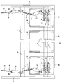
- FIGS. 1 to 5 show an article storage device 2 according to the embodiment.
- Reference numeral 4 denotes a frame which supports a plurality of elevating frames 6 so as to be movable up and down.
- the suspension member 8 is composed of an upper chain 10 and a lower pendant 12.
- the chain 10 may be a rope, a wire, or other rope, and the pendant 12 may be a plate-like weight and may have a bar shape or the like.
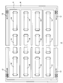
- the article storage device 2 includes a conveyor 14 composed of a plurality of individual belt conveyors, and instead of the belt conveyor, a roller conveyor, a chain conveyor, or the like may be used.
- a conveyor 14 composed of a plurality of individual belt conveyors, and instead of the belt conveyor, a roller conveyor, a chain conveyor, or the like may be used.
- the tip of the pendant 12 (attachment position of the chain 10) should face the inside of the article storage device 2, but the pendant 12 may fall down so as to face the outside of the article storage device 2.
- the elevating frame 6 is lowered, if the chain 10 falls outside for some reason, the pendant 12 may fall outside. Then, troubles such as the pendant 12 interfering with the frame 4 occur, and the elevating frame 6 cannot be stacked regularly.
- the length of the chain 10 needs to be slightly larger than the shortest length connecting the attachment position to the pendant 12 and the attachment position to the upper lift frame 6 with a straight line when the lift frames 6 are stacked. is there. However, due to this clearance, if the chain 10 becomes an unnatural shape with the lifting frames 6 stacked, the lifting frames 6 cannot be stacked regularly.
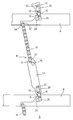
- the embodiment uses the plate 20 and the stopper 24 shown in FIGS. 3 and 4 to prevent the pendant 12 from falling outward of the lifting frame 6.
- the pendant 12 and the lifting frame 6 are connected to each other by a link plate 16 and a pair of upper and lower pins 18 and 19.
- the plate 20 fixed with the pins 18 and 19 and the pin 22 extends from the pendant 12 side to the lower lifting frame 6 side through the pins 22, 18 and 19 and beyond the pin 19.
- the direction of the plate 20, the link plate 16, and the pendant 12 is the same, and the horizontal pin 19 serves as an axis fulcrum of the pendant 12, and supports the pendant 12 so as to be rotatable in the vertical plane.
- the surface facing the inner side of the elevating frame 6 on the side surface of the front end of the plate 20 forms an abutment surface 26 and abuts against a stopper 24 made of a bolt head or the like.
- the stopper 24 is fastened to the lifting frame 6 by a nut or a female screw cut into the lifting frame 6. Therefore, as shown in FIG. 3, the pendant 12 can only be tilted toward the inside of the lifting frame 6.
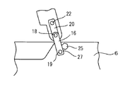
- the stopper 24 only needs to prevent the pendant 12 from falling outward of the lifting frame 6, and may be, for example, a pin head or a projection such as a weld piece. Further, as in the modification of FIG.
- a stopper 25 may be provided on the outer side of the elevating frame 6 as viewed from the pin 19 and regulated by the contact surface 27. Contrary to the embodiment, the pendant 12 and the chain 10 may be tilted toward the outside of the lifting frame 6.
- the link plate 16 is a member that reinforces the plate 20 and may be omitted.
- FIG. 7 and FIG. 8 show a second modification example regarding the restriction of the orientation of the pendant 12.
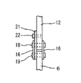
- Reference numeral 21 denotes a new plate through which the pins 22, 18 and 19 are passed, and the direction of the link plate 16 and the direction of the pendant 12 are equalized by the plate 21.
- Reference numeral 30 denotes a stopper that abuts the curved surface at the tip of the pendant 12 and prohibits the pendant 12 from falling outside the lifting frame 6. That is, when the pendant 12 tries to fall outside the lifting frame 6 clockwise from the state of FIGS. 7 and 8, the stopper 30 is in contact with the curved surface at the tip of the pendant 12 and the pendant 12 is prohibited from falling.
- FIG. 5 shows a countermeasure for this in the embodiment.
- a stopper 28 such as a hexagonal head of a bolt is provided on the outside of the lifting frame 6 and below the chain 10 when viewed from the mounting pin 31 of the chain 10 to the pendant 12.
- the stopper 28 may be a square head of a pin or a weld piece.
- Reference numeral 32 denotes a pin for attaching the chain 10 to the lifting frame 6.
- Each link plate of the chain 10, particularly the first link plate 33 has, for example, straight side edges and at least a side edge in contact with the stopper 28.
- the link plate 33 and the like are enlarged and shown in the lower left of FIG.
- the first link plate 33 stands upward in contact with the side edge of the stopper 28, thereby absorbing the play of the chain 10, and the chain 10 is aligned substantially parallel to the upper surface of the lifting frame 6. That is, when the elevating frame 6 is stacked up and down, the first link plate 33 stands vertically, and thereafter, the chain 10 extends toward the attachment portion of the pendant 12 to the elevating frame 6 in parallel with the upper side of the pendant 12.
- the chain 10 is bent upward at the link plate 34 or in front of the link plate 34 and attached to the upper pendant 12.
- the pendant 12 can be prevented from falling in the opposite direction.
- the chain 10 can be folded into an aligned shape with a simple structure.
Landscapes
- Engineering & Computer Science (AREA)
- Mechanical Engineering (AREA)
- Warehouses Or Storage Devices (AREA)
- Load-Engaging Elements For Cranes (AREA)
Abstract
剛体(12)が所定の向きにのみ倒れるようにすることにより、吊り下げ部材(8)が所定の形状に折り畳まれるようにする。吊り下げ部材(8)により上下に連結した複数の昇降枠(6)と、コンベヤ(14)とを備える物品収納装置(2)の吊り下げ部材(8)を、上側の昇降枠に取り付けられた上部の索体(10)と、下側の昇降枠に鉛直面内で回動自在に取り付けられた下部の剛体(12)とで構成する。剛体(12)が所定の向きにのみ倒れるように規制する、規制部材(20、24、30)を昇降枠(6)に設ける。
Description
この発明は昇降枠を複数積層した物品収納装置に関し、特に昇降枠を連結する吊り下げ部材に関する。
複数の昇降枠をチェーンなどの索体で連結して昇降させる、物品収納装置が知られている。そしてコンベヤの搬送面を、昇降枠が上下に通過するようにして、コンベヤと昇降枠との間で複数の物品を一括して移載する。昇降枠を規則的に積み重ねるには、索体を所定の形状に折り畳む必要がある。この点に関して、特許文献1(JP2003-63617A)は、吊り下げ部材を上部の索体と下部のペンダント(板状の錘)とで構成することを開示している。
しかしながら発明者は、昇降枠を下降させる際に、ペンダントが本来の向きとは逆向きに倒れることがあることを見出した。このようなことが生じると、昇降枠を規則的に積み重ねることができない。そこで簡単な構造で、ペンダントが所定の向きにのみ倒れるようにして、昇降枠を所定の形状に積み重ねることを検討して、この発明に到った。
この発明の課題は、ペンダント等の剛体が所定の向きにのみ倒れるようにすることにより、吊り下げ部材が所定の形状に折り畳まれるようにすることにある。
この発明での追加の課題は、昇降枠を積み重ねた際に、索体が所定の形状になるようにすることにある。
この発明での追加の課題は、昇降枠を積み重ねた際に、索体が所定の形状になるようにすることにある。
この発明は、吊り下げ部材により上下に連結した複数の昇降枠と、コンベヤとを備えて、昇降枠をコンベヤの搬送面を越えて上昇させることにより物品を昇降枠に収納し、コンベヤの搬送面を越えて下降させることにより、複数の昇降枠を積み重ねるようにした物品収納装置であって、
前記吊り下げ部材を、上側の昇降枠に取り付けられた上部の索体と、下側の昇降枠に鉛直面内で回動自在に取り付けられた下部の剛体とで構成すると共に、
前記剛体が所定の向きにのみ倒れるように規制する、規制部材を前記昇降枠に設けたことを特徴とする。
前記吊り下げ部材を、上側の昇降枠に取り付けられた上部の索体と、下側の昇降枠に鉛直面内で回動自在に取り付けられた下部の剛体とで構成すると共に、
前記剛体が所定の向きにのみ倒れるように規制する、規制部材を前記昇降枠に設けたことを特徴とする。
またこの発明は、吊り下げ部材により上下に連結された複数の昇降枠とコンベヤとを備える物品収納装置により、物品を昇降枠に収納する方法であって、
前記吊り下げ部材は、上側の昇降枠に取り付けられた上部の索体と、下側の昇降枠に鉛直面内で回動自在に取り付けられた下部の剛体とで構成され、
前記剛体を規制する規制部材が前記昇降枠に設けられ、
昇降枠をコンベヤの搬送面を越えて上昇させることにより、物品を昇降枠に収納するステップと、
コンベヤの搬送面を越えて下降させることにより複数の昇降枠を積み重ねると共に、前記規制部材により前記剛体が所定の向きにのみ倒れるように規制するステップ、とを実行することを特徴とする。
前記吊り下げ部材は、上側の昇降枠に取り付けられた上部の索体と、下側の昇降枠に鉛直面内で回動自在に取り付けられた下部の剛体とで構成され、
前記剛体を規制する規制部材が前記昇降枠に設けられ、
昇降枠をコンベヤの搬送面を越えて上昇させることにより、物品を昇降枠に収納するステップと、
コンベヤの搬送面を越えて下降させることにより複数の昇降枠を積み重ねると共に、前記規制部材により前記剛体が所定の向きにのみ倒れるように規制するステップ、とを実行することを特徴とする。
この発明では、昇降枠を積み重ねる際に、例えば剛体が昇降枠の内側にのみ倒れるようにすることにより、複数の昇降枠を規則的に積み重ねることができる。
また好ましくは、前記剛体は昇降枠に軸支部で軸支され、前記規制部材は、前記剛体から前記軸支部を越えて昇降枠側へ延びる当接部材と、前記当接部材を規制するストッパとから成る。昇降枠は軸支部よりも下側にスペースの余裕がある。従って、この部分にストッパを設けると、ストッパを高い強度で設けることができ、また昇降枠を積み重ねる際にストッパが邪魔にならない。
特に好ましくは、前記当接部材は前記剛体に固定された板状部材で、前記ストッパは昇降枠に締結された締結部材からなる。このようにすると、簡単かつ安価に当接部材とストッパとを構成できる。
特に好ましくは、前記当接部材は前記剛体に固定された板状部材で、前記ストッパは昇降枠に締結された締結部材からなる。このようにすると、簡単かつ安価に当接部材とストッパとを構成できる。
好ましくは、前記剛体を倒した状態で、前記索体が所定の形状を取るように、索体を規制する第2の規制部材を、前記剛体に設ける。所定の形状とは例えば、索体が下方の剛体への取付部から鉛直方向に立ち上がり、次いで上方の剛体への取付部へ延びる形状である。このようにすると、昇降枠を積み重ねた際に、索体を所定の形状に揃ることができる。従って、不規則な形状に畳まれた索体のために、昇降枠と昇降枠との間に隙間が開くなどのことがない。
好ましくは、前記第2の規制部材は、前記剛体または昇降枠に締結された締結部材からなる。このようにすると、簡単かつ安価な部材で第2の規制部材を構成できる。
好ましくは、前記第2の規制部材は、前記剛体または昇降枠に締結された締結部材からなる。このようにすると、簡単かつ安価な部材で第2の規制部材を構成できる。
以下に本発明を実施するための最適実施例を示す。この発明の範囲は、特許請求の範囲の記載に基づき、明細書の記載とこの分野での周知技術とを参酌し、当業者の理解に従って定められるべきである。
図1~図8に、実施例とその変形とを示す。図1~図5は実施例の物品収納装置2を示し、4はそのフレームで、複数の昇降枠6を昇降自在に支持している。そして昇降枠6は下降して退避した状態では上下に密着して積み重ねられ、上昇した状態では吊り下げ部材8で定まる間隔で上下に間隔を置いて配置される。吊り下げ部材8は上部のチェーン10と下部のペンダント12から成り、チェーン10はロープ、ワイヤ、その他の索体でもよく、ペンダント12は板状の錘で、棒状などの形状でもよい。物品収納装置2は複数個の個別のベルトコンベヤから成るコンベヤ14を備え、ベルトコンベヤの替わりにローラコンベヤ、チェーンコンベヤ等でも良く、コンベヤの搬送面は例えば水平である。昇降枠6をコンベヤ14の搬送面を越えて上側に移動させることにより、コンベヤ14上の物品を昇降枠6に荷積みし、逆に昇降枠6をコンベヤ14の搬送面を下側へ移動させることにより、昇降枠6からコンベヤ14へ物品を荷下ろしできる。図示しない最上部の昇降枠に対して、チェーンは他の昇降枠6に対するチェーン10よりも長くされ、図示しないスプロケットなどで駆動されるものとする。
昇降枠6を積み重ねると、図1の下部のようになる。このときペンダント12の先端(チェーン10の取付位置)は物品収納装置2の内側を向いているはずであるが、ペンダント12が物品収納装置2の外側を向くように倒れることがある。例えば昇降枠6を下降させた際に、チェーン10が何らかの原因で外側に倒れると、ペンダント12も外側に倒れることがある。するとペンダント12がフレーム4と干渉する等のトラブルを生じ、また昇降枠6を規則的に積み重ねることが出来ない。チェーン10の長さは、昇降枠6を積み重ねた際に、ペンダント12への取付位置と上側の昇降枠6への取付位置の間を直線で結ぶ最短の長さよりも、多少のゆとりが必要である。しかしこのゆとりのために、昇降枠6を積み重ねた状態で、チェーン10が不自然な形状になると、昇降枠6を規則正しく積み重ねることができない。
これらの課題を解決するため、実施例では図3,図4に示すプレート20とストッパ24とを用いて、ペンダント12が昇降枠6の外向きに倒れることを防止する。ペンダント12と昇降枠6とは、リンクプレート16と上下一対のピン18,19で連結されている。またピン18,19ならびにピン22で固定されたプレート20が、ペンダント12側から下側の昇降枠6側へ、ピン22,18,19を通り、かつピン19を越えて延びている。プレート20とリンクプレート16、及びペンダント12の向きは等しく、水平なピン19がペンダント12の軸支点として、ペンダント12を鉛直面内で回動自在に支持する。そしてプレート20の先端部側面で、昇降枠6の内側を向いた面が当接面26をなし、ボルトの頭などから成るストッパ24と当接する。ストッパ24は、ナットあるいは昇降枠6に切り込んだ雌ねじなどにより、昇降枠6に対し締結されている。従って図3に示すように、ペンダント12は昇降枠6の内側向きにしか倒れることができない。ストッパ24は、ペンダント12が昇降枠6の外向きに倒れることを阻止するものであればよく、例えばピンの頭、溶接片等の突起などでもよい。さらに図6の変形例のように、ピン19から見て昇降枠6の外側斜め上方にストッパ25を設けて、当接面27で規制しても良い。なお実施例とは逆に、ペンダント12とチェーン10とが昇降枠6の外側向きに倒れるようにしても良い。またリンクプレート16はプレート20を補強する部材で、無くても良い。
図7,図8に、ペンダント12の向きの規制に関する第2の変形例を示す。21は新たなプレートで、ピン22,ピン18,19が通され、プレート21によりリンクプレート16の向きとペンダント12の向きが等しくなる。30はペンダント12の先端の曲面と当接して、ペンダント12が昇降枠6の外側に倒れることを禁止するストッパである。即ち、図7,図8の状態からペンダント12が時計回りに昇降枠6の外側に倒れようとすると、ストッパ30がペンダント12の先端の曲面と接して、ペンダント12が倒れることを禁止する。
昇降枠6を上下に積み重ねた状態で、チェーン10の形状を所定の形状に揃える必要がある。このことへの実施例での対策を、図5に示す。ペンダント12へのチェーン10の取付ピン31から見て、昇降枠6の外側でチェーン10の下側に、ボルトの6角形の頭などのストッパ28を設ける。ストッパ28はピンの角形の頭、或いは溶接片などでもよい。32はチェーン10を昇降枠6に取り付けるピンである。チェーン10の各リンクプレート、特に最初のリンクプレート33は、例えば両側縁が直線状で、少なくともストッパ28と接する側縁が直線状である。リンクプレート33等を拡大して、図5の左下に示す。最初のリンクプレート33はストッパ28の側縁と接して上向きに立ち、これによってチェーン10の遊びが吸収され、チェーン10は昇降枠6の上面にほぼ平行に整列される。即ち昇降枠6を上下に積み重ねた際に、最初のリンクプレート33が鉛直に立ち、以降はペンダント12の上辺と平行にペンダント12の昇降枠6への取付部へ向けてチェーン10が延び、最後のリンクプレート34もしくはその手前でチェーン10は上向きに曲がって、上側のペンダント12に取り付けられる。
実施例では以下の効果が得られる。
(1) 簡単な構造で、ペンダント12が逆向きに倒れることを防止できる。
(2) 簡単な構造で、チェーン10を整列した形状に折り畳むことができる。
(1) 簡単な構造で、ペンダント12が逆向きに倒れることを防止できる。
(2) 簡単な構造で、チェーン10を整列した形状に折り畳むことができる。
2 物品収納装置 4 フレーム 6 昇降枠 8 吊り下げ部材
10 チェーン 12 ペンダント 14 コンベヤ
16 リンクプレート 18,19 ピン 20,21 プレート
22 ピン 24,25 ストッパ 26,27 当接面
28~30 ストッパ 31,32 ピン
33 最初のリンクプレート 34 最後のリンクプレート
10 チェーン 12 ペンダント 14 コンベヤ
16 リンクプレート 18,19 ピン 20,21 プレート
22 ピン 24,25 ストッパ 26,27 当接面
28~30 ストッパ 31,32 ピン
33 最初のリンクプレート 34 最後のリンクプレート
Claims (6)
- 吊り下げ部材により上下に連結した複数の昇降枠と、コンベヤとを備えて、昇降枠をコンベヤの搬送面を越えて上昇させることにより物品を昇降枠に収納し、コンベヤの搬送面を越えて下降させることにより、複数の昇降枠を積み重ねるようにした物品収納装置であって、
前記吊り下げ部材を、上側の昇降枠に取り付けられた上部の索体と、下側の昇降枠に鉛直面内で回動自在に取り付けられた下部の剛体とで構成すると共に、
前記剛体が所定の向きにのみ倒れるように規制する、規制部材を前記昇降枠に設けたことを特徴とする、物品収納装置。 - 前記剛体は昇降枠に軸支部で軸支され、
前記規制部材は、前記剛体から前記軸支部を越えて昇降枠側へ延びる当接部材と、前記当接部材を規制するストッパとから成ることを特徴とする、請求項1の物品収納装置。 - 前記当接部材は前記剛体に固定された板状部材で、前記ストッパは昇降枠に締結された締結部材からなることを特徴とする、請求項2の物品収納装置。
- 前記剛体を倒した状態で、前記索体が所定の形状を取るように、索体を規制する第2の規制部材を、前記剛体に設けたことを特徴とする、請求項1の物品収納装置。
- 前記第2の規制部材は、前記剛体または昇降枠に締結された締結部材からなることを特徴とする、請求項4の物品収納装置。
- 吊り下げ部材により上下に連結された複数の昇降枠とコンベヤとを備える物品収納装置により、物品を昇降枠に収納する方法であって、
前記吊り下げ部材は、上側の昇降枠に取り付けられた上部の索体と、下側の昇降枠に鉛直面内で回動自在に取り付けられた下部の剛体とで構成され、
前記剛体を規制する規制部材が前記昇降枠に設けられ、
昇降枠をコンベヤの搬送面を越えて上昇させることにより、物品を昇降枠に収納するステップと、
コンベヤの搬送面を越えて下降させることにより複数の昇降枠を積み重ねると共に、前記規制部材により前記剛体が所定の向きにのみ倒れるように規制するステップ、とを実行することを特徴とする物品収納方法。
Priority Applications (1)
| Application Number | Priority Date | Filing Date | Title |
|---|---|---|---|
| JP2012531741A JP5448121B2 (ja) | 2010-09-02 | 2011-07-21 | 物品収納装置及び物品収納方法 |
Applications Claiming Priority (2)
| Application Number | Priority Date | Filing Date | Title |
|---|---|---|---|
| JP2010196449 | 2010-09-02 | ||
| JP2010-196449 | 2010-09-02 |
Publications (1)
| Publication Number | Publication Date |
|---|---|
| WO2012029428A1 true WO2012029428A1 (ja) | 2012-03-08 |
Family
ID=45772538
Family Applications (1)
| Application Number | Title | Priority Date | Filing Date |
|---|---|---|---|
| PCT/JP2011/066556 Ceased WO2012029428A1 (ja) | 2010-09-02 | 2011-07-21 | 物品収納装置及び物品収納方法 |
Country Status (3)
| Country | Link |
|---|---|
| JP (1) | JP5448121B2 (ja) |
| TW (1) | TWI513638B (ja) |
| WO (1) | WO2012029428A1 (ja) |
Citations (4)
| Publication number | Priority date | Publication date | Assignee | Title |
|---|---|---|---|---|
| JP2003063617A (ja) * | 2001-08-29 | 2003-03-05 | Murata Mach Ltd | 物品収納装置 |
| JP2003089407A (ja) * | 2001-09-20 | 2003-03-25 | Murata Mach Ltd | 物品滞留装置 |
| JP2003160201A (ja) * | 2001-11-27 | 2003-06-03 | Junko Aoki | ゴミ分別収納箱 |
| JP2006103935A (ja) * | 2004-10-08 | 2006-04-20 | Ishii Seisakusho:Kk | 多段式物品収納装置 |
Family Cites Families (2)
| Publication number | Priority date | Publication date | Assignee | Title |
|---|---|---|---|---|
| US4926760A (en) * | 1989-01-27 | 1990-05-22 | Sack Allen J | Self leveling tables |
| JPH0812021A (ja) * | 1994-07-04 | 1996-01-16 | Kouritsu Gijutsu Kenkyusho:Kk | 搬送設備における物品滞留装置および物品滞留方法 |
-
2011
- 2011-07-21 WO PCT/JP2011/066556 patent/WO2012029428A1/ja not_active Ceased
- 2011-07-21 JP JP2012531741A patent/JP5448121B2/ja not_active Expired - Fee Related
- 2011-09-01 TW TW100131484A patent/TWI513638B/zh not_active IP Right Cessation
Patent Citations (4)
| Publication number | Priority date | Publication date | Assignee | Title |
|---|---|---|---|---|
| JP2003063617A (ja) * | 2001-08-29 | 2003-03-05 | Murata Mach Ltd | 物品収納装置 |
| JP2003089407A (ja) * | 2001-09-20 | 2003-03-25 | Murata Mach Ltd | 物品滞留装置 |
| JP2003160201A (ja) * | 2001-11-27 | 2003-06-03 | Junko Aoki | ゴミ分別収納箱 |
| JP2006103935A (ja) * | 2004-10-08 | 2006-04-20 | Ishii Seisakusho:Kk | 多段式物品収納装置 |
Also Published As
| Publication number | Publication date |
|---|---|
| TW201223840A (en) | 2012-06-16 |
| TWI513638B (zh) | 2015-12-21 |
| JPWO2012029428A1 (ja) | 2013-10-28 |
| JP5448121B2 (ja) | 2014-03-19 |
Similar Documents
| Publication | Publication Date | Title |
|---|---|---|
| JP6344410B2 (ja) | 天井搬送車 | |
| CN103144934B (zh) | 单主线多输出托盘库自动码垛系统 | |
| CN101549834B (zh) | 升降式吊运输送机 | |
| TWI337974B (en) | Stacker crane | |
| CN103043331B (zh) | 一种可折叠集装箱的平衡装置 | |
| CN113772559B (zh) | 一种缆索吊机索鞍自适应调节系统 | |
| WO2017186078A1 (zh) | 一种消防水带盒 | |
| JP5448121B2 (ja) | 物品収納装置及び物品収納方法 | |
| JP7153897B2 (ja) | 吊り下げ支持機具および搬送方法 | |
| KR101358696B1 (ko) | 지브 크레인 | |
| JP2016124678A (ja) | 線材コイルの吊上げ用の吊上げ装置 | |
| CN209306818U (zh) | 货物吊装架 | |
| JP6669356B2 (ja) | 岸壁クレーンおよび岸壁クレーンの制御方法 | |
| JP5673134B2 (ja) | 昇降装置、揺れ防止治具及び吊り治具 | |
| JP5949636B2 (ja) | 物品収納棚 | |
| CN209685124U (zh) | 一种避免挤压的大件物品起吊支撑架 | |
| KR20120111159A (ko) | 핑거 프레임 기구 | |
| TWI743390B (zh) | 運輸設備的伸縮裝置 | |
| KR20150068616A (ko) | 쌍동선의 횡동요 저감 장치 | |
| JP7829842B2 (ja) | 搬送装置 | |
| CN110790201A (zh) | 一种带吊箱的升降机 | |
| KR102093482B1 (ko) | 자재 이송 시스템 | |
| KR20250134935A (ko) | 코일 이송용 리프트 장치 | |
| JPH107376A (ja) | 搬送装置 | |
| JPH09235091A (ja) | 揚重装置 |
Legal Events
| Date | Code | Title | Description |
|---|---|---|---|
| 121 | Ep: the epo has been informed by wipo that ep was designated in this application |
Ref document number: 11821446 Country of ref document: EP Kind code of ref document: A1 |
|
| WWE | Wipo information: entry into national phase |
Ref document number: 2012531741 Country of ref document: JP |
|
| NENP | Non-entry into the national phase |
Ref country code: DE |
|
| 122 | Ep: pct application non-entry in european phase |
Ref document number: 11821446 Country of ref document: EP Kind code of ref document: A1 |