WO2012029358A1 - X線分析装置および方法 - Google Patents
X線分析装置および方法 Download PDFInfo
- Publication number
- WO2012029358A1 WO2012029358A1 PCT/JP2011/061303 JP2011061303W WO2012029358A1 WO 2012029358 A1 WO2012029358 A1 WO 2012029358A1 JP 2011061303 W JP2011061303 W JP 2011061303W WO 2012029358 A1 WO2012029358 A1 WO 2012029358A1
- Authority
- WO
- WIPO (PCT)
- Prior art keywords
- sample
- ray
- primary
- rays
- angle
- Prior art date
- Legal status (The legal status is an assumption and is not a legal conclusion. Google has not performed a legal analysis and makes no representation as to the accuracy of the status listed.)
- Ceased
Links
- 0 CC(*)CCCN Chemical compound CC(*)CCCN 0.000 description 1
Images



Classifications
-
- G—PHYSICS
- G01—MEASURING; TESTING
- G01N—INVESTIGATING OR ANALYSING MATERIALS BY DETERMINING THEIR CHEMICAL OR PHYSICAL PROPERTIES
- G01N23/00—Investigating or analysing materials by the use of wave or particle radiation, e.g. X-rays or neutrons, not covered by groups G01N3/00 – G01N17/00, G01N21/00 or G01N22/00
- G01N23/22—Investigating or analysing materials by the use of wave or particle radiation, e.g. X-rays or neutrons, not covered by groups G01N3/00 – G01N17/00, G01N21/00 or G01N22/00 by measuring secondary emission from the material
- G01N23/223—Investigating or analysing materials by the use of wave or particle radiation, e.g. X-rays or neutrons, not covered by groups G01N3/00 – G01N17/00, G01N21/00 or G01N22/00 by measuring secondary emission from the material by irradiating the sample with X-rays or gamma-rays and by measuring X-ray fluorescence
-
- G—PHYSICS
- G01—MEASURING; TESTING
- G01N—INVESTIGATING OR ANALYSING MATERIALS BY DETERMINING THEIR CHEMICAL OR PHYSICAL PROPERTIES
- G01N2223/00—Investigating materials by wave or particle radiation
- G01N2223/07—Investigating materials by wave or particle radiation secondary emission
- G01N2223/076—X-ray fluorescence
Definitions
- the present invention relates to an X-ray analysis apparatus and method for measuring an arbitrary measurement site of a disk-shaped sample such as a wafer.
- the surface of a sample is irradiated with primary X-rays, and the intensity of secondary X-rays generated from the sample surface is detected and analyzed.
- secondary X-rays such as fluorescent X-rays and diffraction X-rays are generated.
- this diffracted X-ray may be an obstacle to measurement. Diffracted X-rays are generated at different angular positions depending on the cut surface of the sample such as the (110) plane and (111) plane, which are crystal structures.
- the sample prior to fluorescent X-ray analysis of the sample, the sample is irradiated with primary X-rays while rotating the sample around a predetermined point of the sample by 180 ° (degrees) or more, and fluorescent X-rays generated from the sample and Secondary X-rays including diffracted X-rays are detected, and the sample is positioned at a rotational position where the obtained secondary X-ray intensity has a minimum value.
- the sample is placed in a plane parallel to the measurement surface.
- Patent Document 1 There is a fluorescent X-ray analysis method in which the sample is moved in the XY directions orthogonal to each other to analyze the entire measurement surface of the sample.
- the primary X-ray 2 in measurement of a desired measurement site near the edge of the sample, the primary X-ray 2 is irradiated from outside the region above the sample S so as to be totally reflected to the region. As a result, a part of the primary X-ray 2 is irradiated onto the vertical end surface of the plate-like sample S, and strong scattered rays 9 are generated in all directions. A part of the scattered radiation 9 becomes a large background with respect to the fluorescent X-ray to be measured.
- an arbitrary measurement site in the vicinity of the edge of the sample is positioned so that the primary X-ray is irradiated from the region above the sample and totally reflected outside the region, and the scattered radiation generated from the end surface of the sample is
- Patent Document 2 a total reflection X-ray fluorescence analyzer that suppresses and measures
- JP-A-5-126768 Japanese Patent Laid-Open No. 2002-5858
- the fluorescent X-ray analysis method described in Patent Document 1 can avoid diffracted X-rays generated from a sample whose crystal structure is rotationally symmetric, but avoid diffracted X-rays generated from a sample whose crystal structure is not rotationally symmetric. I could't.
- the total reflection X-ray fluorescence analyzer described in Patent Document 2 can suppress the influence of scattered radiation generated from the vicinity of the edge of the sample, but avoids diffracted X-rays generated from a sample whose crystal structure is not rotationally symmetric. Therefore, even if the sample is set at a position where the influence of scattered radiation can be eliminated, diffracted X-rays cannot be avoided, and depending on the sample, accurate analysis cannot be performed.
- An object of the present invention is to provide an X-ray analysis apparatus and method capable of easily performing accurate analysis by avoiding diffracted X-rays generated from a sample.
- an X-ray analyzer includes a sample stage on which a disk-shaped sample having a crystal structure is placed, and an X-ray that irradiates the sample with primary X-rays.
- a source for detecting secondary X-rays generated from the sample
- translation means for translating the sample stage so that the primary X-ray is irradiated at an arbitrary position on the sample measurement surface
- sample measurement Rotating means for rotating the sample stage about an axis perpendicular to the surface, and the primary X-rays are irradiated from the region above the sample to an arbitrary measurement site in the vicinity of the sample edge. Measured so that it reflects to the back.
- the X-ray analyzer irradiates the sample with a primary X-ray from the X-ray source while rotating the sample around a predetermined point of the sample by the rotation means by 360 °, and generates the sample to enter the detector.
- the display unit displays a diffraction pattern in which the intensity of the secondary X-ray corresponds to the rotation angle of the sample, and stores the diffraction pattern in the same direction as the horizontal component of the primary X-ray to the sample.
- the sample that can be positioned on the measurement surface of the sample in the R- ⁇ coordinate of the sample in the R- ⁇ coordinate of the sample.
- Calculation storage means for calculating and / or storing the upper and lower limit values of the range for each sample diameter, upper and lower limit values of ⁇ coordinates calculated and / or stored by the measurer by the calculation storage means, and The display hand And a selection means for selecting an avoidance angle at which the adjacent interval is an angle within the upper and lower limit value range of the ⁇ coordinate based on the diffraction pattern displayed in FIG.
- the means stores the avoidance angle selected by the measurer using the selection means, and reads the avoidance angle closest to the coordinate of the measurement point from the stored avoidance angles according to the coordinates of the measurement point of the sample. Then, the rotating means is controlled to set the sample at the read avoidance angle, and the parallel moving means is controlled to set the sample measurement point to the primary X-ray irradiation position.
- the X-ray analyzer of the first configuration of the present invention while suppressing and avoiding scattered rays and impurity lines generated from the vicinity of the edge of the disk-shaped sample having a crystal structure and the device structure in the vicinity of the sample, By avoiding the generated diffracted X-rays, it is possible to easily analyze with high accuracy.
- the X-ray analyzer of the second configuration of the present invention includes a sample stage on which a disk-shaped sample having a crystal structure is placed, an X-ray source that irradiates the sample with primary X-rays, and 2 generated from the sample.
- a detector for detecting a secondary X-ray a translation means for translating the sample stage so that the primary X-ray is irradiated at an arbitrary position on the sample measurement surface, and an axis perpendicular to the sample measurement surface.
- a rotation means for rotating the sample stage, and an arbitrary measurement site near the edge of the sample is positioned so that the primary X-ray is irradiated from the region above the sample and reflected outside the region. taking measurement.
- the X-ray analyzer irradiates the sample with a primary X-ray from the X-ray source while rotating the sample around a predetermined point of the sample by the rotation means by 360 °, and generates the sample to enter the detector.
- the display means displays a diffraction pattern in which the intensity of the secondary X-ray corresponds to the rotation angle of the sample, and the control selection means for storing the diffraction pattern and the same direction as the horizontal component of the primary X-ray to the sample.
- Two imaginary lines that are directed and that are in contact with the outer circumference of the field of view of the detector on the sample measurement surface can be positioned on the sample measurement surface in the R- ⁇ coordinate of the sample.
- Calculation storage means for calculating and / or storing the upper and lower limit ⁇ coordinates of the movement range for each diameter of the sample, and the control selection means calculates and / or stored by the calculation storage means Up and down coordinates Based on the value and the diffraction pattern displayed on the display means, the adjacent interval is an angle within an upper and lower limit range of the ⁇ coordinate, and the diffraction pattern has an X-ray intensity equal to or lower than a predetermined threshold value and is diffracted.
- An avoidance angle capable of avoiding X-rays is selected and stored, and according to the coordinates of the measurement point of the sample, the avoidance angle closest to the coordinate of the measurement point is read out from the stored avoidance angles, and the rotating means is controlled. Then, the sample is set to the read avoidance angle, and the measurement unit of the sample is set to the irradiation position of the primary X-ray by controlling the parallel moving means.
- the X-ray analyzer of the second configuration of the present invention it is possible to automatically suppress and avoid scattered rays and impurity lines generated from the vicinity of the edge of the disk-shaped sample having a crystal structure and the device structure in the vicinity of the sample. At the same time, by avoiding the diffracted X-rays generated from the sample, it is possible to easily analyze with high accuracy.
- the X-ray analysis method of the third configuration of the present invention includes a sample stage on which a disk-shaped sample having a crystal structure is placed, an X-ray source that irradiates the sample with primary X-rays, and 2 generated from the sample.
- a detector for detecting a secondary X-ray a translation means for translating the sample stage so that the primary X-ray is irradiated at an arbitrary position on the sample measurement surface, and an axis perpendicular to the sample measurement surface.
- a rotation means for rotating the sample stage, and an arbitrary measurement site near the edge of the sample is positioned so that the primary X-ray is irradiated from the region above the sample and reflected outside the region.
- An X-ray analyzer to be measured is used.
- the sample placed on the sample stage is irradiated with primary X-rays while being rotated 360 ° around a predetermined point of the sample by the rotating means, and the detector is generated from the sample.
- Two imaginary lines oriented in the same direction as the horizontal component of the primary X-ray to the sample and in contact with the outer periphery of the field of view of the detector on the measurement surface of the sample are R- ⁇ coordinates of the sample.
- the upper and lower limit ⁇ coordinates of the upper and lower limit values of the parallel movement range of the sample that can be positioned on the measurement surface of the sample are calculated and stored for each diameter of the sample, and the upper and lower limit values of the calculated and stored ⁇ coordinates, and Based on the diffraction pattern displayed on the display means, an adjacent angle is an angle within an upper and lower limit range of ⁇ coordinates, and an avoidance angle that can avoid diffraction X-rays is selected, and the rotation means selects the selected angle.
- the sample is set at the avoidance angle, and the measurement point of the sample is set to the irradiation position of the primary X-ray by the parallel moving means for analysis.
- the X-ray analysis method of the third configuration of the present invention while suppressing and avoiding scattered rays and impurity lines generated from the vicinity of the edge of the disk-shaped sample having a crystal structure and the device structure in the vicinity of the sample, By avoiding the generated diffracted X-rays, it is possible to easily analyze with high accuracy.
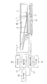
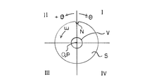
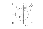
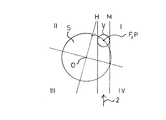
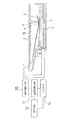
- FIG. 1 is a schematic diagram showing an X-ray analysis apparatus according to a first embodiment of the present invention. It is a figure which shows the initial position of the sample in the sample stand of the apparatus. It is a figure which shows the diffraction pattern of the sample measured with the same apparatus. It is a figure which shows the positional relationship of the measurement point A of the same apparatus, and a virtual line.
- FIG. 1 is a schematic configuration diagram of an X-ray analyzer such as a total reflection fluorescent X-ray analyzer used for carrying out the X-ray analysis method of the present invention.
- This X-ray analyzer has a crystal structure such as a wafer.
- X-ray source 1 such as an X-ray tube that emits primary X-rays 2 toward a disk-shaped sample S having a fluorescent X-ray and diffracted X-rays generated from the sample S by the irradiation of primary X-rays 2
- the detector 7 for detecting the intensity of the secondary X-ray 4 such as the sample stage 8, the sample stage 8 on which the sample S is placed, and the sample stage 8 are rotated around an axis perpendicular to the measurement surface of the sample S.
- the rotating means 11 that rotates around the center O of the sample S and the primary X-ray 2 is irradiated to an arbitrary position on the measurement surface of the sample S in a state where the rotating means 11 is rotatably supported.
- a parallel moving means 12 such as an R- ⁇ stage for moving in the R- ⁇ direction in a plane parallel to the measurement surface.
- the R- ⁇ stage is a stage disclosed in JP-A-8-161049.
- the coordinates of the sample S are indicated by R- ⁇ coordinates.
- the clockwise angle in the R- ⁇ coordinate is indicated as - ⁇
- the counterclockwise angle is indicated as + ⁇
- the rotation angle in the counterclockwise direction rotated by is indicated by a symbol ⁇ .
- the sample S is placed on the sample stage 8 and is set to the initial position with reference to the notch N of the wafer, the orientation flat, or the like.
- the center O of the sample S coincides with the center P of the field of view V of the detector 7.
- Symbols I, II, III, and IV shown in Fig. 2 indicate the first quadrant, the second quadrant, the third quadrant, and the fourth quadrant of coordinates.
- FIG. 1 shows that an arbitrary measurement site in the vicinity of the edge of the sample S can be measured by being irradiated with the primary X-ray 2 from the region 10 above the sample S and reflected outside the region 10.
- the primary X-ray 2 is irradiated near the right edge of the sample S from the left side of the drawing.
- the irradiation direction of the primary X-ray 2 to the sample S is fixed in a predetermined direction.
- the detector 7 is a semiconductor detector such as an SDD.
- the detector 7 is fixed to a predetermined part of the apparatus, and the visual field V on the sample S measurement surface has a constant size (a constant area).
- the field of view V of the detector 7 is circular, and the radius T is 10 mm.
- the X-ray analysis apparatus further includes a control unit 15, a display unit 16, a calculation storage unit 17, and a selection unit 18.
- the control means 15 emits the primary X-ray 2 from the X-ray source 1 while rotating the sample S around the center O of the sample S 360 ° counterclockwise by the rotating means 11, and is generated from the sample S and detected by the detector 7 displays a diffraction pattern in which the intensity of the secondary X-ray 4 incident on 7 corresponds to the rotation angle ⁇ of the sample S on the display means 16 and stores the diffraction pattern.
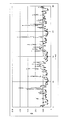
- FIG. 3 shows an example of a diffraction pattern acquired by irradiating the primary X-ray WL-L ⁇ 1 with the apparatus of the present embodiment, displayed on the display means 16, and stored. Note that the rotation direction of the sample S may be clockwise.
- the arithmetic storage means 17 is an imaginary line facing the same direction as the horizontal component of the primary X-ray 2 to the sample S, and is two imaginary lines in contact with the outer periphery of the field of view of the detector 7 on the measurement surface of the sample.
- the ⁇ coordinates of the upper and lower limit values of the translation range of the sample S that can be positioned on the measurement surface of the sample S are calculated and / or stored for each diameter R of the sample S.
- the imaginary line is indicated by the symbols H and M shown in FIG. 4 and faces the same direction as the horizontal component of the primary X-ray 2 and is on the outer periphery of the visual field V of the detector 7 on the measurement surface of the sample S. It is a virtual line that touches. As described with reference to FIG.
- the irradiation direction of the primary X-ray 2 onto the sample S is fixed in the direction indicated by the arrow in FIG. 4 and the field of view V of the detector 7 is also constant.
- M are at fixed positions shown in FIG.
- the measuring point A is arranged at the center P of the field of view V of the detector 7 and measured by the translation means 12.
- the measurer uses the selection unit 18 to set the adjacent interval to the upper limit of the ⁇ coordinate based on the upper and lower limit values of the ⁇ coordinate calculated or stored by the calculation storage unit 17 and the diffraction pattern displayed on the display unit 16. An avoidance angle that is within the lower limit range and that can avoid diffracted X-rays is selected.
- the control means 15 uses the selection means 18 to store the selected avoidance angle ⁇ , and according to the measurement point coordinates of the sample S, the closest avoidance angle ⁇ among the stored avoidance angles ⁇ .
- the angle ⁇ is read, the sample S is set to the read avoidance angle ⁇ by controlling the rotating means 11, and the sample S is moved while the set avoidance angle ⁇ is maintained by controlling the parallel moving means 12.
- the measurement point is made to coincide with the center P of the field of view V of the detector 7.
- the ⁇ coordinates of the upper and lower limits of the parallel movement range of the sample S in which the two virtual lines H and M can be positioned on the measurement surface of the sample S in the R- ⁇ coordinate of the sample S.
- the right virtual line M is outside the measurement surface of the sample S, and the primary X-ray 2 Hits the right edge of the sample S, and scattered rays are generated. Further, the primary X-ray 2 is irradiated on the device structural material existing below the sample S (in the depth direction of the drawing in FIG.
- the left virtual line H is on the measurement surface of the sample S
- the right virtual line M is It contacts the right side surface of the sample S. Therefore, even if a part of the primary X-rays 2 is irradiated to the right side edge of the sample S or the apparatus structural material existing below the sample S, scattered rays and impure lines generated from those portions are not detected by the detector 7. The light travels outside the field of view V and does not enter the detector 7.
- the scattered rays and the impure lines are detected by the detector. 7 can be prevented from entering.
- the left imaginary line H and the right imaginary line M are both on the measurement surface of the sample S, and ⁇ 1 (FIG. 6) of the measurement point C and the measurement point D
- the angle relationship of ⁇ 2 is ⁇ 1> ⁇ 2.
- the first quadrant coordinate of the sample S has been described, the same applies to the second quadrant coordinate. If the position of the measurement point is within the angle range of 0 to + ⁇ 1, both scattered rays and impure lines are incident on the detector 7. You can avoid it. That is, if the position of the measurement point is within the angle range of ⁇ 1 to + ⁇ 1, it is possible to prevent both scattered rays and impure lines from entering the detector 7, + ⁇ 1 being the upper limit angle, and ⁇ 1 being the lower limit angle, The angle range of the absolute value is 2 ⁇ 1.
- the following relationship (1) is established among the upper limit angle ⁇ 1, the radius R of the sample S, and the radius T of the field of view V of the detector 7.
- the detector 7 is fixed to a predetermined part of the apparatus, the radius T of the field of view V of the detector 7 is also constant, and the upper limit angle ⁇ 1 can be obtained from the radius R of the sample S.
- the calculation storage means 17 stores the above equation (1) and the radius T of the detector field.
- the calculation is performed to obtain the upper and lower limit angles ⁇ ⁇ 1 and 2 ⁇ 1. Are displayed on the display means 16 and stored.
- the sample S is placed on the sample stage 8 shown in FIG. 1 by the sample transport means (not shown).
- the sample S is moved from the initial position on the sample stage 8 by the parallel moving means 12, and is set to a measurement point E (R1, 0) that is less affected by scattered rays from the sample edge as shown in FIG. .
- the measurement point E is irradiated with the primary X-ray 2 from the X-ray source 1, and the sample S
- the secondary X-ray 4 including the fluorescent X-ray and the diffracted X-ray generated from is detected by the detector 7.
- FIG. 3 shows a diffraction pattern of the measured W-L ⁇ line (W), where the horizontal axis represents the rotation angle ⁇ of the sample S and the vertical axis represents the X-ray intensity of the W-L ⁇ line.
- the measurer inputs the radius R of the sample S from the input means 19 to the calculation storage means 17.
- the calculation storage means 17 calculates the upper and lower limit angles ⁇ ⁇ 1 and 2 ⁇ 1 based on the above equation (1), and displays and stores them on the display means 16.
- the detector visual field radius T is 10 mm
- the sample radius R is 100 mm
- ⁇ 1 is 64 °
- 2 ⁇ 1 is 128 °.
- the radius R of the sample S is input and calculated by the calculation storage means 17 to obtain the upper and lower limit angles ⁇ ⁇ 1 and 2 ⁇ 1, but a silicon wafer, a liquid crystal glass, a hard disk, which is the sample S having a crystal structure,
- the diameter of a magnetic disk or the like is standardized to 50 mm (2 inches), 76 mm (3 inches), 100 mm, 125 mm, 150 mm, 200 mm, 300 mm, and the like. It is also possible to store the upper and lower limit angles ⁇ ⁇ 1 and 2 ⁇ 1 corresponding to and read them at the time of measurement.
- the measurer avoids the diffracted X-rays in which the intensity of the diffracted X-rays is low in the diffraction pattern shown in FIG.
- the angle is selected by the selection means 18. At this time, for example, 25 °, so that the angle width of the adjacent angular position of the selected avoidance angle is less than the angle range 2 ⁇ 1 calculated by the calculation storage means 17, in this embodiment, less than 128 °. Select 95 °, 180 °, 260 °, 345 °. The avoidance angle selected by the selection means 18 is registered.
- control means 15 When registered, the control means 15 stores the avoidance angle as a measurement condition, and each position of the avoidance angles 25 °, 95 °, 180 °, 260 °, and 345 ° on the diffraction pattern displayed on the display means 16. A vertical line avoidance angle mark is displayed on the screen.
- the selected avoidance angle mark is displayed on the diffraction pattern, it is easily visible whether the angle width of the adjacent angular position of the selected avoidance angle is an avoidance angle of less than 128 °. can do. Furthermore, when the angle width exceeds 128 °, it cannot be registered. Thus, the angle width can be reliably set to an avoidance angle of less than 128 °.
- the avoidance angle ⁇ 1 closest to the ⁇ coordinate of the measurement point is read from the avoidance angles stored by the control means 15, and the sample S is set to the avoidance angle ⁇ 1 by the rotation means 11.
- the measurement point is shifted counterclockwise by the angle ⁇ 1 from the field of view V of the detector 7, so that the control means 15 controls the parallel moving means 12 and is set.
- the sample S is moved in a state where the avoidance angle ⁇ 1 is maintained, and the measurement point is made to coincide with the center P of the field of view V of the detector 7.
- the sample S is set by the rotating means 11 at an avoidance angle of ⁇ 15 °.
- the measurement point F is shifted ⁇ 15 ° counterclockwise from the field of view V of the detector 7, so that the control means 15 moves in parallel as shown in FIG.
- the means 12 is controlled to move the sample S while maintaining the set avoidance angle of ⁇ 15 ° so that the measurement point F coincides with the center P of the field of view V of the detector 7.
- the sample S is set at an avoidance angle of ⁇ 15 ° (345 °) avoiding the diffracted X-rays, and the measurement point F of the sample S is irradiated with the primary X-ray 2 from the X-ray source 1,
- the generated secondary X-ray 4 is detected by a detector 7 and analyzed.
- the control means 15 controls the rotation means 11 according to the coordinates, and any of avoidance angles 25 °, 95 °, 180 °, 260 °, and 345 ° to avoid diffracted X-rays from the sample S.
- the parallel movement means 12 is controlled to set the measurement point of the sample S to the irradiation position of the primary X-ray and analyze it.
- the measurement points other than the vicinity of the edge of the sample S are similarly analyzed.
- sample S having a diameter of 200 mm has been described, the samples S having other diameters are similarly analyzed.
- the apparatus structure near the edge of the sample S and the vicinity of the sample S according to the diameter R of the sample S having a crystal structure.
- this apparatus does not include the control means 15 and the selection means 18 of the X-ray analysis apparatus of the first embodiment, but includes a control selection means 20 instead, and the other configurations are the same. Only different configurations will be described.
- the control selection means 20 emits the primary X-ray 2 from the X-ray source 1 while rotating the sample S around the predetermined point of the sample S by 360 ° by the rotation means 11, and is generated from the sample S and incident on the detector 7.
- a diffraction pattern in which the intensity of the secondary X-ray 4 is made to correspond to the rotation angle of the sample S is displayed on the display means 16 and the diffraction pattern is stored.
- the stored diffraction pattern (FIG. 3) is scanned with a predetermined X-ray intensity threshold, and X-ray intensity below this threshold exists over a predetermined angular range, for example, 3 ° to 5 °, this predetermined
- the center angle position of the angle range is stored as an avoidance angle.
- the central angle position is, for example, 25 °, 95 °, 180 °, 260 °, 345 °, or the like.
- the control selection unit 20 Based on the upper and lower limit values of the ⁇ coordinate calculated and / or stored by the calculation storage unit 17 and the diffraction pattern displayed on the display unit 16, the control selection unit 20 sets the adjacent interval between the upper and lower limit value ranges of the ⁇ coordinate. And an avoidance angle ⁇ 1 that is an X-ray intensity equal to or less than a predetermined threshold in the diffraction pattern and that can avoid the diffraction X-ray is selected and stored, and according to the coordinates of the measurement point of the sample S, The avoidance angle ⁇ 1 closest to the coordinates of the measurement point is read from the stored avoidance angle ⁇ 1, and the rotating means 11 is controlled so as to set the sample S at the avoidance angle ⁇ 1.
- the measurement point is shifted counterclockwise by the angle ⁇ 1 from the field of view V of the detector 7, so that the control selecting means 20 controls the parallel moving means 12 to set.
- the measurement point is moved to the center P of the field of view V of the detector 7 while maintaining the avoided angle ⁇ 1.
- the apparatus according to the third embodiment does not include the control means 15 and the selection means 18 of the apparatus according to the first embodiment, but includes a control selection means 20 instead.
- the other configurations are the same, and therefore only different operations are performed. explain.
- the measurer avoids the diffracted X-rays in which the intensity of the diffracted X-rays is low from the diffraction patterns displayed on the display means 16 and does not show a sharp increase in intensity at the adjacent angular positions.
- the avoidance angle is selected by the selection means 18, in the apparatus of the third embodiment, the control selection means 20 automatically selects and stores the avoidance angle, and the avoidance angle closest to the coordinates of the measurement point among the stored avoidance angles.
- the parallel movement means 12 and the rotation means 11 are controlled to automatically set the sample S at the avoidance angle, and the measurement point is set in the field of view V of the detector 7 while the set avoidance angle is maintained. Move to center P and analyze.
- the X-ray analysis apparatus of the third embodiment or the method of the fourth embodiment automatically from the vicinity of the edge of the sample S and the apparatus structure near the sample S according to the diameter of the sample S having a crystal structure.
- the total reflection X-ray fluorescence analyzer has been described.
- an energy dispersive X-ray fluorescence analyzer a wavelength dispersive X-ray fluorescence analyzer, etc. may be used.
- the present invention may be any X-ray analyzer that needs to avoid scattering and impurity lines generated from the sample S having a crystal structure and avoid diffracted X-rays.
- a fluorescent X-ray analyzer, X It may be a composite X-ray analyzer in which a line reflectivity measuring device, an X-ray diffractometer or the like is combined.
Landscapes
- Physics & Mathematics (AREA)
- Health & Medical Sciences (AREA)
- Life Sciences & Earth Sciences (AREA)
- Chemical & Material Sciences (AREA)
- Analytical Chemistry (AREA)
- Biochemistry (AREA)
- General Health & Medical Sciences (AREA)
- General Physics & Mathematics (AREA)
- Immunology (AREA)
- Pathology (AREA)
- Analysing Materials By The Use Of Radiation (AREA)
Abstract
本発明のX線分析装置は、試料(S)を試料(S)の所定点周りに360°回転させながら1次X線(2)を照射させて取得した回折パターンを記憶する制御手段(15)と、試料(S)のR-θ座標において試料(S)の測定面上に位置することができる試料(S)の平行移動範囲の上下限値のθ座標を、演算および/または記憶する演算記憶手段(17)と、演算および/または記憶されたθ座標の上下限値、および回折パターンに基づいて、隣り合う間隔がθ座標の上下限値範囲内の角度であって、回折X線を回避できる回避角度を選択するための選択手段(18)とを備え、制御手段(15)が試料(S)の測定点の座標に応じて、回避角度の中から測定点の座標に最も近い回避角度を読み出して、読み出した回避角度に試料(S)を設定する。
Description
本出願は、2010年8月31日出願の特願2010-193677の優先権を主張するものであり、その全体を参照により本願の一部をなすものとして引用する。
本発明は、ウエーハ等の円板状の試料の任意の測定部位を測定するX線分析装置およびその方法に関する。
従来、例えば、ウエーハの分析には、試料表面に1次X線を照射して、試料表面から発生する2次X線の強度を検出して分析している。ウエーハなどの結晶構造を有する試料はX線が照射されると、蛍光X線、回折X線などの2次X線を発生する。蛍光X線分析において、この回折X線が測定の障害となる場合がある。回折X線は結晶構造である(110)面、(111)面などの試料のカット面によって発生する角度位置が異なる。
そこで、試料の蛍光X線分析に先立って、試料を試料の所定点周りに180°(度)以上回転させながら、この試料に1次X線を照射して、試料から発生する蛍光X線および回折X線を含む2次X線を検出し、得られた2次X線強度が最小値を示す回転方向位置に試料を位置決めし、この状態で、試料を、その測定面に平行な面内で互いに直交するXY方向に移動させて、試料の測定面全域の分析を行なう蛍光X線分析方法がある(特許文献1)。
また、図11に示すように、試料の縁近傍にある所望の測定部位の測定において、試料Sの上方の領域外から1次X線2が照射されて前記領域へ全反射するように位置させて測定すると、1次X線2の一部が板状の試料Sの鉛直な端面に照射され、四方に向けて強い散乱線9が発生する。この散乱線9の一部は、測定すべき蛍光X線に対して大きなバックグラウンドとなる。
そこで、試料の縁近傍にある任意の測定部位について、試料の上方の領域から1次X線が照射されて前記領域外へ全反射するように位置させて、試料の端面から発生する散乱線を抑制して、測定する全反射蛍光X線分析装置がある(特許文献2)。
特許文献1に記載の蛍光X線分析方法では、結晶構造が回転対称の試料から発生する回折X線を回避することはできるが、結晶構造が回転対称でない試料から発生する回折X線を回避することができなかった。
特許文献2に記載の全反射蛍光X線分析装置では、試料の縁近傍から発生する散乱線の影響を抑制することができるが、結晶構造が回転対称でない試料から発生する回折X線を回避することを考慮していないので、散乱線の影響を排除できる位置に試料を設定しても回折X線を回避することできず、試料によっては精度のよい分析ができなかった。
そこで、本発明は前記従来の問題に鑑みてなされたもので、結晶構造を有する円板状の試料の縁近傍ならびに試料近傍の装置構造物から発生する散乱線および不純線を抑制回避するとともに、試料から発生する回折X線を回避することによって、簡単に精度のよい分析をすることができるX線分析装置および方法を提供することを目的とする。
前記目的を達成するために、本発明の第1構成のX線分析装置は、結晶構造を有する円板状の試料が載置される試料台と、試料に1次X線を照射するX線源と、試料から発生する2次X線を検出する検出器と、試料測定面の任意の位置に1次X線が照射されるように前記試料台を平行移動させる平行移動手段と、試料測定面に垂直な軸を中心に前記試料台を回転させる回転手段と、を備え、試料の縁近傍にある任意の測定部位について、試料の上方の領域から1次X線が照射されて前記領域外へ反射するように位置させて測定する。
さらに、このX線分析装置は、試料を試料の所定点周りに前記回転手段によって360°回転させながら前記X線源から1次X線を照射させ、試料から発生して前記検出器に入射する2次X線の強度を試料の回転角度と対応させた回折パターンを表示手段に表示させ、その回折パターンを記憶する制御手段と、試料への1次X線の水平方向成分と同一方向を向いた仮想線であって、試料の測定面上における前記検出器の視野の外周に接する2つの仮想線が、試料のR-θ座標において試料の測定面上に位置することができる試料の平行移動範囲の上下限値のθ座標を、試料の直径ごとに、演算および/または記憶する演算記憶手段と、測定者が前記演算記憶手段によって演算および/または記憶されたθ座標の上下限値、ならびに前記表示手段に表示された回折パターンに基づいて、隣り合う間隔がθ座標の上下限値範囲内の角度であって、回折X線を回避できる回避角度を選択するための選択手段と、を備え、前記制御手段が、測定者によって前記選択手段を用いて選択された回避角度を記憶し、試料の測定点の座標に応じて、前記記憶した回避角度の中から測定点の座標に最も近い回避角度を読み出して、前記回転手段を制御して前記読み出した回避角度に試料を設定し、前記平行移動手段を制御して試料の測定点を1次X線の照射位置に設定する。
本発明の第1構成のX線分析装置によれば、結晶構造を有する円板状の試料の縁近傍ならびに試料近傍の装置構造物から発生する散乱線および不純線を抑制回避するとともに、試料から発生する回折X線を回避することによって、簡単に精度のよい分析をすることができる。
本発明の第2構成のX線分析装置は、結晶構造を有する円板状の試料が載置される試料台と、試料に1次X線を照射するX線源と、試料から発生する2次X線を検出する検出器と、試料測定面の任意の位置に1次X線が照射されるように前記試料台を平行移動させる平行移動手段と、試料測定面に垂直な軸を中心に前記試料台を回転させる回転手段と、を備え、試料の縁近傍にある任意の測定部位について、試料の上方の領域から1次X線が照射されて前記領域外へ反射するように位置させて測定する。
さらに、このX線分析装置は、試料を試料の所定点周りに前記回転手段によって360°回転させながら前記X線源から1次X線を照射させ、試料から発生して前記検出器に入射する2次X線の強度を試料の回転角度と対応させた回折パターンを表示手段に表示させ、その回折パターンを記憶する制御選択手段と、試料への1次X線の水平方向成分と同一方向を向いた仮想線であって、試料の測定面上における前記検出器の視野の外周に接する2つの仮想線が、試料のR-θ座標において試料の測定面上に位置することができる試料の平行移動範囲の上下限値のθ座標を、試料の直径ごとに、演算および/または記憶する演算記憶手段と、を備え、前記制御選択手段が、前記演算記憶手段によって演算および/または記憶されたθ座標の上下限値、ならびに前記表示手段に表示された回折パターンに基づいて、隣り合う間隔がθ座標の上下限値範囲内の角度であって、前記回折パターンにおいて所定の閾値以下のX線強度であって回折X線を回避できる回避角度を選択して記憶し、試料の測定点の座標に応じて、前記記憶した回避角度の中から測定点の座標に最も近い回避角度を読み出して、前記回転手段を制御して前記読み出した回避角度に試料を設定し、前記平行移動手段を制御して試料の測定点を1次X線の照射位置に設定する。
本発明の第2構成のX線分析装置によれば、自動的に、結晶構造を有する円板状の試料の縁近傍ならびに試料近傍の装置構造物から発生する散乱線および不純線を抑制回避するとともに、試料から発生する回折X線を回避することによって、簡単に精度のよい分析をすることができる。
本発明の第3構成のX線分析方法は、結晶構造を有する円板状の試料が載置される試料台と、試料に1次X線を照射するX線源と、試料から発生する2次X線を検出する検出器と、試料測定面の任意の位置に1次X線が照射されるように前記試料台を平行移動させる平行移動手段と、試料測定面に垂直な軸を中心に前記試料台を回転させる回転手段と、を備え、試料の縁近傍にある任意の測定部位について、試料の上方の領域から1次X線が照射されて前記領域外へ反射するように位置させて測定するX線分析装置を用いる。
さらに、このX線分析方法は、前記試料台に載置された試料を前記回転手段によって試料の所定点周りに360°回転させながら1次X線を照射させ、試料から発生して前記検出器に入射する2次X線の強度を試料の回転角度と対応させた回折パターンを取得し、
試料への1次X線の水平方向成分と同一方向を向いた仮想線であって、試料の測定面上における前記検出器の視野の外周に接する2つの仮想線が、試料のR-θ座標において試料の測定面上に位置することができる試料の平行移動範囲の上下限値のθ座標を、試料の直径ごとに、演算して記憶し、演算記憶されたθ座標の上下限値、および前記表示手段に表示された回折パターンに基づいて、隣り合う間隔がθ座標の上下限値範囲内の角度であって、回折X線を回避できる回避角度を選択し、前記回転手段によって前記選択した回避角度に試料を設定し、前記平行移動手段によって試料の測定点を1次X線の照射位置に設定して分析する。
試料への1次X線の水平方向成分と同一方向を向いた仮想線であって、試料の測定面上における前記検出器の視野の外周に接する2つの仮想線が、試料のR-θ座標において試料の測定面上に位置することができる試料の平行移動範囲の上下限値のθ座標を、試料の直径ごとに、演算して記憶し、演算記憶されたθ座標の上下限値、および前記表示手段に表示された回折パターンに基づいて、隣り合う間隔がθ座標の上下限値範囲内の角度であって、回折X線を回避できる回避角度を選択し、前記回転手段によって前記選択した回避角度に試料を設定し、前記平行移動手段によって試料の測定点を1次X線の照射位置に設定して分析する。
本発明の第3構成のX線分析方法によれば、結晶構造を有する円板状の試料の縁近傍ならびに試料近傍の装置構造物から発生する散乱線および不純線を抑制回避するとともに、試料から発生する回折X線を回避することによって、簡単に精度のよい分析をすることができる。
この発明は、添付の図面を参考にした以下の好適な実施形態の説明からより明瞭に理解されるであろう。しかしながら、実施形態および図面は単なる図示および説明のためのものであり、この発明の範囲を定めるために利用されるべきでない。この発明の範囲は添付の請求の範囲によって定まる。添付図面において、複数の図面における同一の部品番号は、同一部分を示す。
本発明の第1実施形態のX線分析装置を示す概略図である。
同装置の試料台における試料の初期位置を示す図である。
同装置によって測定した試料の回折パターンを示す図である。
同装置の測定点Aと仮想線との位置関係を示す図である。
同装置の測定点Bと仮想線との位置関係を示す図である。
同装置の測定点Cと仮想線との位置関係を示す図である。
同装置の測定点Dと仮想線との位置関係を示す図である。
同装置によって回折パターンを取得するときの試料位置を示す図である。
同装置の測定点Fが回折X線回避角度に設定された図である。
本発明の第3実施形態のX線分析装置を示す概略図である。
従来のX線分析装置における試料からの散乱線発生部分の拡大図である。
以下、本発明の第1実施形態のX線分析装置について説明する。まず、X線分析装置の構成について、図にしたがって説明する。図1は、この発明のX線分析方法を実施するために使用する全反射蛍光X線分析装置などのX線分析装置の概略構成図であり、このX線分析装置は、ウエーハなどの結晶構造を有する円板状の試料Sに向けて1次X線2を照射するX線管などのX線源1と、1次X線2の照射によって試料Sから発生する蛍光X線、回折X線などの2次X線4の強度を検出する検出器7と、試料Sを載置する試料台8と、この試料台8を試料Sの測定面に垂直な軸を中心に回転させる、この実施形態では試料Sの中心O周りに回転させる回転手段11と、この回転手段11を回転可能に支持した状態で、試料Sの測定面の任意の位置に1次X線2が照射されるように測定面に平行な面内でR-θ方向に移動させるR-θステージなどの平行移動手段12とを備えている。例えば、R-θステージは特開平8-161049に開示されているステージである。
試料Sの座標はR-θ座標で示され、図2に示すように、R-θ座標において時計方向の角度を-θ、反時計方向の角度を+θと表示し、試料Sが回転手段11によって回転される反時計方向の回転角度を符号ωと表示する。試料Sは試料台8に載置され、ウエーハのノッチNやオリフラ(orientation flat)などを基準として初期位置に設定される。試料Sの初期位置において、試料Sの中心Oと検出器7の視野Vの中心Pとは合致している。図2に示す符号I 、II、III 、IVは座標の第1象限、第2象限、第3象限、第4象限を示している。
試料Sの縁近傍にある任意の測定部位について、試料Sの上方の領域10から1次X線2が照射されて前記領域10外へ反射するように位置させて測定できるように、図1に示すように1次X線2を紙面の左方から試料Sの右側縁近傍に照射している。1次X線2の試料Sへの照射方向は所定の方向に固定されている。検出器7はSDDなどの半導体検出器である。検出器7は装置の所定の部位に固定されており、試料S測定面上の視野Vは一定の大きさ(一定面積)となる。第1実施形態のX線分析装置では、例えば、検出器7の視野Vは円形であり、半径Tは10mmである。
第1実施形態のX線分析装置は、さらに、制御手段15、表示手段16、演算記憶手段17および選択手段18を備えている。制御手段15は、試料Sを試料Sの中心O周りに回転手段11によって反時計方向に360°回転させながらX線源1から1次X線2を照射させ、試料Sから発生して検出器7に入射する2次X線4の強度を試料Sの回転角度ωと対応させた回折パターンを表示手段16に表示させ、その回折パターンを記憶する。本実施形態の装置で1次X線W-Lβ1を照射して取得され、表示手段16に表示されて記憶された回折パターンの例を図3に示す。なお、試料Sの回転方向は時計方向であってもよい。
演算記憶手段17は、試料Sへの1次X線2の水平方向成分と同一方向を向いた仮想線であって、試料の測定面上における検出器7の視野の外周に接する2つの仮想線が、試料Sの測定面上に位置することができる試料Sの平行移動範囲の上下限値のθ座標を、試料Sの直径Rごとに、演算および/または記憶する。仮想線は、図4に示す符号Hと符号Mで表示され、1次X線2の水平方向成分と同一方向を向いており、試料Sの測定面上における検出器7の視野Vの外周に接する仮想の線である。図1で説明したように1次X線2の試料Sへの照射方向は図4の矢印で示す方向に固定されており、検出器7の視野Vも一定であるので、2つの仮想線H、Mは図4に示す一定位置にある。平行移動手段12によって測定点Aが検出器7の視野Vの中心Pに配置されて測定される。
測定者は、選択手段18を用いて、演算記憶手段17によって演算または記憶されたθ座標の上下限値、および表示手段16に表示された回折パターンに基づいて、隣り合う間隔がθ座標の上下限値範囲内の角度であって、回折X線を回避できる回避角度を選択する。
制御手段15が、選択手段18を用いて、選択された回避角度ωを記憶し、試料Sの測定点の座標に応じて、前記記憶した回避角度ωの中から測定点の座標に最も近い回避角度ωを読み出して、回転手段11を制御して前記読み出した回避角度ωに試料Sを設定し、平行移動手段12を制御して、設定された回避角度ωを維持した状態で試料Sを移動させて測定点を検出器7の視野Vの中心Pに合致させる。
2つの仮想線H、Mが試料SのR-θ座標において試料Sの測定面上に位置することができる、試料Sの平行移動範囲の上下限値のθ座標について、以下に説明する。測定点B(R、-90)と検出器7の視野Vとの位置が図5に示す状態であると、右側仮想線Mが試料Sの測定面上の外側にあり、1次X線2が試料Sの右側エッジに当たり、散乱線が発生する。また、1次X線2が試料Sの下方に(図5の紙面奥方向)存在する装置構造材に照射され散乱線と不純線(試料Sの下方に存在する装置構造材から発生する蛍光X線)が発生する。このようにして発生した最初の散乱線と不純線が、さらなる散乱線と不純線を発生させる。最初の散乱線と不純線、および、さらなる散乱線と不純線が検出器7に入射する。
一方、測定点C(R、-θ1)と検出器7の視野Vとの位置が図6に示す状態であると、左側仮想線Hは試料Sの測定面上にあり、右側仮想線Mは試料Sの右側側面に接している。したがって、一部の1次X線2が試料Sの右側エッジや試料Sの下方に存在する装置構造材に照射されても、それらの個所から発生した散乱線および不純線は、検出器7の視野Vの外側に進行し、検出器7には入射しない。
このように、左側仮想線Hと右側仮想線Mの2つの仮想線がともに試料Sの測定面上に位置するように平行移動手段12によって試料Sを配置すると、散乱線および不純線が検出器7に入射しないようにすることができる。
図7に示す測定点D(R、-θ2)については、左側仮想線Hと右側仮想線Mはともに試料Sの測定面上にあり、測定点Cのθ1(図6)と測定点Dのθ2の角度関係は、θ1>θ2である。これから分かるように、測定点の位置が0~-θ1の角度範囲であれば、散乱線および不純線が検出器7に入射しないようにすることができる。
試料Sの第1象限座標について説明したが、第2象限座標についても同様に考えられ、測定点の位置が0~+θ1の角度範囲内であれば、散乱線と不純線ともに検出器7に入射しないようにすることができる。すなわち、測定点の位置が-θ1~+θ1の角度範囲内であれば、散乱線と不純線ともに検出器7に入射しないようにすることができ、+θ1が上限角度、-θ1が下限角度となり、絶対値の角度範囲としては2θ1となる。
図6に示すように、上限角度θ1、試料Sの半径Rおよび検出器7の視野Vの半径Tとの間には、下記の(1)式の関係が成立する。
sinθ1=(R-T)/R (1)
検出器7は装置の所定の部位に固定されており、その検出器7の視野Vの半径Tも一定であり、試料Sの半径Rによって上限角度θ1を求めることができる。
演算記憶手段17には、上記(1)式および検出器視野の半径Tが格納されており、入力手段19によって試料半径Rが入力されると、演算して上下限角度±θ1および2θ1を求め、表示手段16に表示するとともに記憶する。
次に、第1実施形態のX線分析装置の動作とともに、本発明の第2実施形態のX線分析方法について説明する。直径200mmの試料Sの全反射蛍光X線分析に先立って、試料Sの360°の回折パターンを取得する。
すなわち、試料Sが試料搬送手段(図示なし)によって図1に示す試料台8に載置される。試料Sが試料台8に載置された初期位置から平行移動手段12によって移動され、図8に示すように試料エッジからの散乱線の影響が少ない測定点E(R1、0)に設定される。回転手段11によって試料台8および試料Sを、試料Sの中心Oの周りに反時計方向に360°回転させながら、測定点EにX線源1から1次X線2を照射し、試料Sから発生する蛍光X線および回折X線を含んだ2次X線4を検出器7により検出する。これによって、図3に示す回折パターンが表示手段16に表示されるとともに制御手段15に記憶される。図3では、測定されたW-Lβ線(W)の回折パターンを示しており、横軸は試料Sの回転角度ω、縦軸はW-Lβ線のX線強度を表している。
次に、測定者が入力手段19から演算記憶手段17に試料Sの半径Rを入力する。演算記憶手段17は試料Sの半径Rが入力されると、上記(1)式に基づいて、演算して上下限角度±θ1および2θ1を求め、表示手段16に表示するとともに記憶する。本実施形態では、検出器視野の半径Tが10mm、試料半径Rは100mmであり、θ1として64°、2θ1として128°が求まる。
上記の例では、試料Sの半径Rを入力し、演算記憶手段17によって演算して上下限角度±θ1および2θ1を求めたが、結晶構造を有する試料Sであるシリコンウエーハ、液晶ガラス、ハードディスク、磁気ディスクなどは、半導体業界において、その直径は、50mm(2インチ)、76mm(3インチ)、100mm、125mm、150mm、200mm、300mmなどに規格化されているので、演算記憶手段17に試料直径に対応した上下限角度±θ1および2θ1を記憶させ、測定時にそれを読み出してもよい。
次に、測定者が、表示手段16に表示された図3の回折パターンの中から回折X線の強度が低く、近接する角度位置において急激な強度増加を示さない、回折X線を回避する回避角度を選択手段18によって選択する。このとき、選択された回避角度の隣り合う角度位置の角度幅が、演算記憶手段17によって演算された角度範囲2θ1未満の角度、本実施形態では128°未満になるように、例えば、25°、95°、180°、260°、345°を選択する。選択手段18によって選択した回避角度を登録する。登録されると、制御手段15がその回避角度を測定条件として記憶し、表示手段16に表示された回折パターン上に回避角度25°、95°、180°、260°、345°のそれぞれの位置に縦線の回避角度マークが表示される。
このように、選択された回避角度マークが回折パターン上に表示されるので、選択した回避角度の隣り合う角度位置の角度幅が128°未満の回避角度になっているか、否かを容易に視認することができる。さらに、角度幅が128°を超えている場合には、登録することができない。このように、角度幅を128°未満の回避角度に確実に設定できるようになっている。
次に、測定を開始すると、制御手段15が記憶した回避角度の中から測定点のθ座標に最も近い回避角度ω1を読み出して、回転手段11によって回避角度ω1に試料Sを設定する。回転手段11によって試料Sが回避角度ω1に設定されると、測定点は検出器7の視野Vから反時計方向に角度ω1ずれるので、制御手段15が平行移動手段12を制御して、設定された回避角度ω1を維持した状態で試料Sを移動させて測定点を検出器7の視野Vの中心Pに合致させる。
例えば、測定点F(100、-30)の測定を開始すると、制御手段15が記憶している回避角度の中から測定点Fのθ座標の角度位置に最も近い回避角度-15°(345°)を読み出して、回転手段11によって回避角度-15°に試料Sを設定する。回転手段11によって試料Sが-15°に回転されると、測定点Fは検出器7の視野Vから反時計方向に-15°ずれるので、図9に示すように、制御手段15が平行移動手段12を制御して、設定された回避角度-15°を維持した状態で試料Sを移動させて測定点Fを検出器7の視野Vの中心Pに合致させる。
これにより、試料Sは回折X線を回避した回避角度-15°(345°)に設定され、試料Sの測定点FにX線源1から1次X線2が照射されて、試料Sから発生する2次X線4を検出器7により検出して分析する。その他の測定点についても座標に応じて、制御手段15が回転手段11を制御して試料Sからの回折X線を回避する回避角度25°、95°、180°、260°、345°のいずれかに設定し、平行移動手段12を制御して試料Sの測定点を1次X線の照射位置に設定して分析する。試料Sの縁近傍以外の測定点についても同様にして分析される。
直径200mmの試料Sについて説明したが、その他の直径の試料Sについても、同様に分析される。
このように、第1の実施形態のX線分析装置または第2の実施形態の方法によれば、結晶構造を有する試料Sの直径Rに応じて試料Sの縁近傍ならびに試料S近傍の装置構造物から発生する散乱線および不純線を抑制回避するとともに、試料Sから発生する回折X線を回避することによって、簡単に精度のよい分析をすることができる。
次に、本発明の第3実施形態のX線分析装置について説明する。図10に示すように、この装置は第1実施形態のX線分析装置の制御手段15と選択手段18とを備えず、それに換わって制御選択手段20を備え、その他の構成は同じであるので、異なる構成のみについて説明する。
制御選択手段20は、試料Sを試料Sの所定点周りに回転手段11によって360°回転させながらX線源1から1次X線2を照射させ、試料Sから発生して検出器7に入射する2次X線4の強度を試料Sの回転角度と対応させた回折パターンを表示手段16に表示させ、その回折パターンを記憶する。記憶した回折パターン(図3)を所定のX線強度閾値で走査して、この閾値以下のX線強度が所定の角度範囲、例えば、3°~5°にわたって存在していると、この所定の角度範囲の中心角度位置を回避角度として記憶する。この中心角度位置は、例えば、25°、95°、180°、260°、345°などである。
制御選択手段20は、演算記憶手段17によって演算および/または記憶されたθ座標の上下限値、ならびに表示手段16に表示された回折パターンに基づいて、隣り合う間隔がθ座標の上下限値範囲内の角度であって、前記回折パターンにおいて所定の閾値以下のX線強度であって回折X線を回避できる回避角度ω1を選択して記憶し、試料Sの測定点の座標に応じて、前記記憶した回避角度ω1の中から測定点の座標に最も近い回避角度ω1を読み出して、その回避角度ω1に試料Sを設定するように回転手段11を制御する。回転手段11によって試料Sが回避角度ω1に設定されると、測定点は検出器7の視野Vから反時計方向に角度ω1ずれるので、制御選択手段20が平行移動手段12を制御して、設定された回避角度ω1を維持した状態で測定点を検出器7の視野Vの中心Pに移動させる。
次に、第3実施形態のX線分析装置の動作とともに、第4実施形態のX線分析方法について説明する。第3実施形態の装置は、第1実施形態の装置の制御手段15と選択手段18とを備えず、それに換わって制御選択手段20を備え、その他の構成は同じであるので、異なる動作のみについて説明する。
第1実施形態の装置では、測定者が表示手段16に表示された回折パターンの中から回折X線の強度が低く、近接する角度位置において急激な強度増加を示さない、回折X線を回避する回避角度を選択手段18によって選択したが、第3実施形態の装置では、制御選択手段20が回避角度を自動選択して記憶し、記憶した回避角度の中から測定点の座標に最も近い回避角度を読み出して、平行移動手段12と回転手段11とを制御して、その回避角度に試料Sを自動設定するとともに、設定された回避角度を維持した状態で測定点を検出器7の視野Vの中心Pに移動させて分析する。
第3の実施形態のX線分析装置または第4実施形態の方法によれば、自動的に、結晶構造を有する試料Sの直径に応じて試料Sの縁近傍ならびに試料S近傍の装置構造物から発生する散乱線および不純線を抑制回避するとともに、試料Sから発生する回折X線を回避することによって、より簡単に精度のよい分析をすることができる。
本実施形態のX線分析装置では、全反射蛍光X線分析装置について説明したが、全反射型でないエネルギー分散型蛍光X線分析装置、波長分散型蛍光X線分析装置などであってもよい。本発明は、結晶構造を有する試料Sから発生する散乱線および不純線を抑制回避し、回折X線を回避する必要のあるX線分析装置であればよく、例えば、蛍光X線分析装置、X線反射率測定装置、X線回折装置などが組み合わされた複合型のX線分析装置であってもよい。
以上のとおり、図面を参照しながら好適な実施例を説明したが、当業者であれば、本件明細書を見て、自明な範囲内で種々の変更および修正を容易に想定するであろう。したがって、そのような変更および修正は、添付の請求の範囲から定まるこの発明の範囲内のものと解釈される。
1 X線源
2 1次X線
4 2次X線
7 検出器
8 試料台
10 試料の上方の領域
11 回転手段
12 平行移動手段
15 制御手段
16 表示手段
17 演算記憶手段
18 選択手段
20 制御選択手段
S 試料
2 1次X線
4 2次X線
7 検出器
8 試料台
10 試料の上方の領域
11 回転手段
12 平行移動手段
15 制御手段
16 表示手段
17 演算記憶手段
18 選択手段
20 制御選択手段
S 試料
Claims (3)
- 結晶構造を有する円板状の試料が載置される試料台と、
試料に1次X線を照射するX線源と、
試料から発生する2次X線を検出する検出器と、
試料測定面の任意の位置に1次X線が照射されるように前記試料台を平行移動させる平行移動手段と、
試料測定面に垂直な軸を中心に前記試料台を回転させる回転手段と、
を備え、
試料の縁近傍にある任意の測定部位について、試料の上方の領域から1次X線が照射されて前記領域外へ反射するように位置させて測定するX線分析装置であって、
試料を試料の所定点周りに前記回転手段によって360°回転させながら前記X線源から1次X線を照射させ、試料から発生して前記検出器に入射する2次X線の強度を試料の回転角度と対応させた回折パターンを表示手段に表示させ、その回折パターンを記憶する制御手段と、
試料への1次X線の水平方向成分と同一方向を向いた仮想線であって、試料の測定面上における前記検出器の視野の外周に接する2つの仮想線が、試料のR-θ座標において試料の測定面上に位置することができる試料の平行移動範囲の上下限値のθ座標を、試料の直径ごとに、演算および/または記憶する演算記憶手段と、
測定者が前記演算記憶手段によって演算および/または記憶されたθ座標の上下限値、ならびに前記表示手段に表示された回折パターンに基づいて、隣り合う間隔がθ座標の上下限値範囲内の角度であって、回折X線を回避できる回避角度を選択するための選択手段と、
を備え、
前記制御手段が、測定者によって前記選択手段を用いて選択された回避角度を記憶し、試料の測定点の座標に応じて、前記記憶した回避角度の中から測定点の座標に最も近い回避角度を読み出して、前記回転手段を制御して前記読み出した回避角度に試料を設定し、前記平行移動手段を制御して試料の測定点を1次X線の照射位置に設定するX線分析装置。 - 結晶構造を有する円板状の試料が載置される試料台と、
試料に1次X線を照射するX線源と、
試料から発生する2次X線を検出する検出器と、
試料測定面の任意の位置に1次X線が照射されるように前記試料台を平行移動させる平行移動手段と、
試料測定面に垂直な軸を中心に前記試料台を回転させる回転手段と、
を備え、
試料の縁近傍にある任意の測定部位について、試料の上方の領域から1次X線が照射されて前記領域外へ反射するように位置させて測定するX線分析装置であって、
試料を試料の所定点周りに前記回転手段によって360°回転させながら前記X線源から1次X線を照射させ、試料から発生して前記検出器に入射する2次X線の強度を試料の回転角度と対応させた回折パターンを表示手段に表示させ、その回折パターンを記憶する制御選択手段と、
試料への1次X線の水平方向成分と同一方向を向いた仮想線であって、試料の測定面上における前記検出器の視野の外周に接する2つの仮想線が、試料のR-θ座標において試料の測定面上に位置することができる試料の平行移動範囲の上下限値のθ座標を、試料の直径ごとに、演算および/または記憶する演算記憶手段と、
を備え、
前記制御選択手段が、前記演算記憶手段によって演算および/または記憶されたθ座標の上下限値、ならびに前記表示手段に表示された回折パターンに基づいて、隣り合う間隔がθ座標の上下限値範囲内の角度であって、前記回折パターンにおいて所定の閾値以下のX線強度であって回折X線を回避できる回避角度を選択して記憶し、試料の測定点の座標に応じて、前記記憶した回避角度の中から測定点の座標に最も近い回避角度を読み出して、前記回転手段を制御して前記読み出した回避角度に試料を設定し、前記平行移動手段を制御して試料の測定点を1次X線の照射位置に設定するX線分析装置。 - 結晶構造を有する円板状の試料が載置される試料台と、
試料に1次X線を照射するX線源と、
試料から発生する2次X線を検出する検出器と、
試料測定面の任意の位置に1次X線が照射されるように前記試料台を平行移動させる平行移動手段と、
試料測定面に垂直な軸を中心に前記試料台を回転させる回転手段と、
を備え、
試料の縁近傍にある任意の測定部位について、試料の上方の領域から1次X線が照射されて前記領域外へ反射するように位置させて測定するX線分析装置を用いるX線分析方法であって、
前記試料台に載置された試料を前記回転手段によって試料の所定点周りに360°回転させながら1次X線を照射させ、試料から発生して前記検出器に入射する2次X線の強度を試料の回転角度と対応させた回折パターンを取得し、
試料への1次X線の水平方向成分と同一方向を向いた仮想線であって、試料の測定面上における前記検出器の視野の外周に接する2つの仮想線が、試料のR-θ座標において試料の測定面上に位置することができる試料の平行移動範囲の上下限値のθ座標を、試料の直径ごとに、演算して記憶し、
演算記憶されたθ座標の上下限値、および前記表示手段に表示された回折パターンに基づいて、隣り合う間隔がθ座標の上下限値範囲内の角度であって、回折X線を回避できる回避角度を選択し、前記回転手段によって前記選択した回避角度に試料を設定し、前記平行移動手段によって試料の測定点を1次X線の照射位置に設定して分析するX線分析方法。
Applications Claiming Priority (2)
| Application Number | Priority Date | Filing Date | Title |
|---|---|---|---|
| JP2010193677A JP4884553B1 (ja) | 2010-08-31 | 2010-08-31 | X線分析装置および方法 |
| JP2010-193677 | 2010-08-31 |
Publications (1)
| Publication Number | Publication Date |
|---|---|
| WO2012029358A1 true WO2012029358A1 (ja) | 2012-03-08 |
Family
ID=45772471
Family Applications (1)
| Application Number | Title | Priority Date | Filing Date |
|---|---|---|---|
| PCT/JP2011/061303 Ceased WO2012029358A1 (ja) | 2010-08-31 | 2011-05-17 | X線分析装置および方法 |
Country Status (2)
| Country | Link |
|---|---|
| JP (1) | JP4884553B1 (ja) |
| WO (1) | WO2012029358A1 (ja) |
Families Citing this family (3)
| Publication number | Priority date | Publication date | Assignee | Title |
|---|---|---|---|---|
| JP5828795B2 (ja) | 2012-04-04 | 2015-12-09 | 信越化学工業株式会社 | 多結晶シリコンの結晶配向度評価方法、多結晶シリコン棒の選択方法、および単結晶シリコンの製造方法 |
| JP2014001096A (ja) | 2012-06-18 | 2014-01-09 | Shin Etsu Chem Co Ltd | 多結晶シリコンの結晶配向度評価方法、多結晶シリコン棒の選択方法、多結晶シリコン棒、多結晶シリコン塊、および、単結晶シリコンの製造方法 |
| KR102718046B1 (ko) | 2018-07-04 | 2024-10-17 | 가부시키가이샤 리가쿠 | 형광 x선 분석 장치 |
Citations (4)
| Publication number | Priority date | Publication date | Assignee | Title |
|---|---|---|---|---|
| JPH0566204A (ja) * | 1990-06-28 | 1993-03-19 | Toshiba Corp | 全反射蛍光x線分析装置 |
| JPH05126768A (ja) * | 1991-11-05 | 1993-05-21 | Rigaku Denki Kogyo Kk | 蛍光x線の分析方法 |
| JPH10282022A (ja) * | 1997-04-08 | 1998-10-23 | Rigaku Ind Co | 蛍光x線分析方法および装置 |
| JP2009210507A (ja) * | 2008-03-06 | 2009-09-17 | Rigaku Corp | 全反射蛍光x線分析装置 |
-
2010
- 2010-08-31 JP JP2010193677A patent/JP4884553B1/ja active Active
-
2011
- 2011-05-17 WO PCT/JP2011/061303 patent/WO2012029358A1/ja not_active Ceased
Patent Citations (4)
| Publication number | Priority date | Publication date | Assignee | Title |
|---|---|---|---|---|
| JPH0566204A (ja) * | 1990-06-28 | 1993-03-19 | Toshiba Corp | 全反射蛍光x線分析装置 |
| JPH05126768A (ja) * | 1991-11-05 | 1993-05-21 | Rigaku Denki Kogyo Kk | 蛍光x線の分析方法 |
| JPH10282022A (ja) * | 1997-04-08 | 1998-10-23 | Rigaku Ind Co | 蛍光x線分析方法および装置 |
| JP2009210507A (ja) * | 2008-03-06 | 2009-09-17 | Rigaku Corp | 全反射蛍光x線分析装置 |
Also Published As
| Publication number | Publication date |
|---|---|
| JP4884553B1 (ja) | 2012-02-29 |
| JP2012052840A (ja) | 2012-03-15 |
Similar Documents
| Publication | Publication Date | Title |
|---|---|---|
| TWI388821B (zh) | 螢光x射線分析裝置及方法 | |
| CN110398506A (zh) | 用于小角x射线散射测量的x射线检测光学器件 | |
| JP5511020B2 (ja) | X線分析装置 | |
| US10648932B2 (en) | Measuring and analyzing residual stresses and their gradients in materials using high resolution grazing incidence X-ray diffraction | |
| JP6886731B2 (ja) | X線分析補助装置及びx線分析装置 | |
| CN107525817A (zh) | X射线衍射装置 | |
| EP3775860B1 (en) | Computed tomographic system calibration | |
| JP6230618B2 (ja) | 面内斜入射回折を用いた表面マッピングのための装置、および、方法 | |
| JP5871393B2 (ja) | X線分析装置 | |
| JP4884553B1 (ja) | X線分析装置および方法 | |
| JP5092052B1 (ja) | X線分析装置および方法 | |
| JP5959057B2 (ja) | X線分析装置 | |
| JP2014013183A (ja) | X線応力測定装置およびx線応力測定方法 | |
| JP6217400B2 (ja) | X線計測用機器およびそのスリット板 | |
| JP5027694B2 (ja) | 全反射蛍光x線分析装置 | |
| CN115420764A (zh) | 基于长方形x射线光束的二维掠入射x射线散射测试装置 | |
| JP2000258366A (ja) | 微小部x線回折装置 | |
| US10393679B2 (en) | Operation guide system for X-ray analysis,operation guide method therefor, and operation guide program therefor | |
| JP2009075018A (ja) | 蛍光x線分析装置および蛍光x線分析方法 | |
| JPH0552775A (ja) | 蛍光x線分析装置 | |
| JP2003254917A (ja) | X線測定装置 |
Legal Events
| Date | Code | Title | Description |
|---|---|---|---|
| 121 | Ep: the epo has been informed by wipo that ep was designated in this application |
Ref document number: 11821376 Country of ref document: EP Kind code of ref document: A1 |
|
| NENP | Non-entry into the national phase |
Ref country code: DE |
|
| 122 | Ep: pct application non-entry in european phase |
Ref document number: 11821376 Country of ref document: EP Kind code of ref document: A1 |