WO2012029218A1 - 電磁開閉器 - Google Patents
電磁開閉器 Download PDFInfo
- Publication number
- WO2012029218A1 WO2012029218A1 PCT/JP2011/003381 JP2011003381W WO2012029218A1 WO 2012029218 A1 WO2012029218 A1 WO 2012029218A1 JP 2011003381 W JP2011003381 W JP 2011003381W WO 2012029218 A1 WO2012029218 A1 WO 2012029218A1
- Authority
- WO
- WIPO (PCT)
- Prior art keywords
- contact
- movable
- fixed
- permanent magnet
- arc
- Prior art date
Links
Images

Classifications
-
- H—ELECTRICITY
- H01—ELECTRIC ELEMENTS
- H01H—ELECTRIC SWITCHES; RELAYS; SELECTORS; EMERGENCY PROTECTIVE DEVICES
- H01H50/00—Details of electromagnetic relays
- H01H50/16—Magnetic circuit arrangements
- H01H50/18—Movable parts of magnetic circuits, e.g. armature
- H01H50/20—Movable parts of magnetic circuits, e.g. armature movable inside coil and substantially lengthwise with respect to axis thereof; movable coaxially with respect to coil
- H01H50/22—Movable parts of magnetic circuits, e.g. armature movable inside coil and substantially lengthwise with respect to axis thereof; movable coaxially with respect to coil wherein the magnetic circuit is substantially closed
-
- H—ELECTRICITY
- H01—ELECTRIC ELEMENTS
- H01H—ELECTRIC SWITCHES; RELAYS; SELECTORS; EMERGENCY PROTECTIVE DEVICES
- H01H50/00—Details of electromagnetic relays
- H01H50/54—Contact arrangements
- H01H50/546—Contact arrangements for contactors having bridging contacts
-
- H—ELECTRICITY
- H01—ELECTRIC ELEMENTS
- H01H—ELECTRIC SWITCHES; RELAYS; SELECTORS; EMERGENCY PROTECTIVE DEVICES
- H01H50/00—Details of electromagnetic relays
-
- H—ELECTRICITY
- H01—ELECTRIC ELEMENTS
- H01H—ELECTRIC SWITCHES; RELAYS; SELECTORS; EMERGENCY PROTECTIVE DEVICES
- H01H50/00—Details of electromagnetic relays
- H01H50/16—Magnetic circuit arrangements
- H01H50/18—Movable parts of magnetic circuits, e.g. armature
- H01H50/30—Mechanical arrangements for preventing or damping vibration or shock, e.g. by balancing of armature
-
- H—ELECTRICITY
- H01—ELECTRIC ELEMENTS
- H01H—ELECTRIC SWITCHES; RELAYS; SELECTORS; EMERGENCY PROTECTIVE DEVICES
- H01H50/00—Details of electromagnetic relays
- H01H50/16—Magnetic circuit arrangements
- H01H50/36—Stationary parts of magnetic circuit, e.g. yoke
-
- H—ELECTRICITY
- H01—ELECTRIC ELEMENTS
- H01H—ELECTRIC SWITCHES; RELAYS; SELECTORS; EMERGENCY PROTECTIVE DEVICES
- H01H50/00—Details of electromagnetic relays
- H01H50/54—Contact arrangements
-
- H—ELECTRICITY
- H01—ELECTRIC ELEMENTS
- H01H—ELECTRIC SWITCHES; RELAYS; SELECTORS; EMERGENCY PROTECTIVE DEVICES
- H01H9/00—Details of switching devices, not covered by groups H01H1/00 - H01H7/00
- H01H9/30—Means for extinguishing or preventing arc between current-carrying parts
- H01H9/44—Means for extinguishing or preventing arc between current-carrying parts using blow-out magnet
- H01H9/443—Means for extinguishing or preventing arc between current-carrying parts using blow-out magnet using permanent magnets
Definitions
- the present invention relates to an electromagnetic switch comprising a contact device having a stationary contact and a movable contact inserted in a current path, and an electromagnet for driving the movable contact.
- an electromagnetic switch such as an electromagnetic relay or electromagnetic contactor that opens and closes a current path, it is movable to shut off the current from the closed state of the contact mechanism in contact with the fixed contactor and the movable contactor to make it open.
- Various mechanisms have been proposed for extinguishing arcs that are generated at the time of opening to separate the contact from the fixed contact.
- an electromagnet block having a pair of fixed contacts that are spaced apart by a predetermined distance, a movable contact that is detachably disposed on the pair of fixed contacts, and a movable iron core that drives the movable contact
- a U-shaped magnetic holding member is arranged outside the sealed container facing both side surfaces of the opposed position of the fixed contact and the movable contact, and an arc is magnetized inside the magnetic holding member.
- an electromagnetic relay having a configuration in which two pairs of permanent magnets are arranged to be easily stretched and extinguished by an arc (see, for example, Patent Document 1).
- a pair of permanent magnets are arranged opposite to each other at a position where the pair of fixed contacts and the movable contact are opposed to each other, so that the movable contacts can be moved from the pair of fixed contacts.
- the arc generated at the time of opening to separate the child is stretched by the magnetic force of the permanent magnet so that the arc can be easily extinguished.
- the vibration shock resistance can be improved, but it is necessary to move the movable iron core against the urging force of the return coil spring when the contact mechanism is closed.
- the present invention has been made paying attention to the above-mentioned unsolved problems of the conventional example, and provides an electromagnetic switch capable of improving the vibration-resistant impact performance without increasing the return biasing force. The purpose is that.
- a first aspect of an electromagnetic switch provides a pair of fixed contacts and a pair of fixed contacts that are fixed within an arc extinguishing chamber container at a predetermined interval.
- a contact device having a movable contact arranged so as to be able to contact and separate, an open position for separating the movable contact from the fixed contact, and a closed position for bringing the movable contact into contact with the fixed contact and further pressing the contact
- an electromagnet device having a movable plunger.
- the arc generated in the arc-extinguishing chamber container at the time of opening when the movable contact is separated from the fixed contact from the closed position where the movable contact is in contact with the fixed contact is extinguished.
- An arcing permanent magnet is provided, and a magnetic circuit is formed from the permanent magnet back to the permanent magnet via the movable plunger with the movable plunger in the open position.
- a second aspect of the electromagnetic switch according to the present invention is such that the permanent magnet faces the movable contact at a position perpendicular to the longitudinal direction of the movable contact on the outside of the opposed side wall of the arc extinguishing chamber container. Arranged.
- the magnetic circuit is disposed between the pair of fixed contacts on the inner surface side of the arc extinguishing chamber container facing the permanent magnet.
- a first magnetic yoke that contacts the movable plunger in the open position a first magnetic yoke that faces the portion of the movable plunger that is opposite to the portion that contacts the first magnetic yoke, and that is in contact with the back side of the permanent magnet. 2 magnetic yokes.
- a magnetic circuit is formed that returns from the permanent magnet to the permanent magnet via the movable plunger while the movable plunger is in the open position. It is possible to obtain the effect of improving the vibration-resistant impact performance without increasing the return biasing force.
- FIG. 2 is a sectional view taken along line AA in FIG. 1.
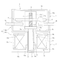
- FIG. 1 is a sectional view showing an example in which the contact device of the present invention is applied to an electromagnetic contactor as an electromagnetic switch.
- reference numeral 1 denotes a contact device
- an electromagnet device 2 is disposed on the lower surface side of the contact device 1.
- the contact device 1 has an arc extinguishing chamber container 3 which is a sealed container in which, for example, a non-magnetic material and an insulator or an inner wall are subjected to insulation treatment, and a contact mechanism 4 is disposed in the arc extinguishing chamber container 3. .
- the arc-extinguishing chamber container 3 includes a bottomed cylindrical body 3a whose lower end surface is opened and a bottom plate portion 3b that closes the lower end surface of the bottomed cylindrical body 3a.
- the bottom plate portion 3b is formed with an insertion hole 3c through which a shaft portion 13a of the movable plunger 13 described later is inserted at the center portion.
- the contact mechanism 4 includes fixed contacts 4 a and 4 b and a movable contact 5. As shown in FIG. 2, the fixed contacts 4 a and 4 b are spaced apart from each other by a predetermined distance on the opposing wall surface of the bottomed cylindrical body 3 a of the arc extinguishing chamber container 3 and the outer end of the arc extinguishing chamber container 3 It is fixedly supported by protruding outward. Further, as shown in FIGS. 1 and 2, the movable contact 5 is formed in a flat plate shape and is opposed to the upper ends of the fixed contacts 4a and 4b so as to be able to contact and separate at a predetermined distance. The movable contact 5 is attached to a contact holder 6 fixedly supported by a movable plunger 13 which will be described later by being biased downward by a contact spring 7.
- an electromagnet device 2 is disposed on the lower surface side of the arc extinguishing chamber container 3.
- the electromagnet device 2 includes a coil bobbin 10 including a cylindrical portion 10a whose axial direction is the vertical direction and flange portions 10b and 10c that protrude outward from both ends thereof.
- An exciting coil 11 is wound around a cylindrical space surrounded by the cylindrical portion 10a and the flange portions 10b and 10c of the coil bobbin 10.
- a bottomed cylindrical body 12 having an open upper end is fitted in the inner peripheral surface of the cylindrical portion 10a of the coil bobbin 10, and a movable plunger 13 made of a magnetic material is movable up and down in the bottomed cylindrical body 12.
- the movable plunger 13 includes a shaft portion 13a inserted into the bottomed cylindrical body 12, a flat plate portion 13b extending in the left-right direction fixed to an end portion of the shaft portion 13a protruding into the arc extinguishing chamber container 3. It is configured in a T shape.
- a contact holder 6 that holds the movable contact 5 is fixedly supported on the flat plate portion 13 b of the movable plunger 13 at the center of the upper surface.
- a return spring 14 is inserted between the lower end surface of the shaft portion 13 a of the movable plunger 13 and the bottom surface of the bottomed cylindrical body 12, and the movable plunger 13 is urged upward by the return spring 14.
- the upper position of the movable plunger 13, that is, the open position is restricted by the flat plate portion 13b coming into contact with a first magnetic yoke described later.
- a second magnetic yoke 15 is disposed on the outer peripheral side of the coil bobbin 10.
- the second magnetic yoke 15 includes an attraction yoke portion 15A that generates an electromagnetic attraction force that attracts the movable plunger 13 against the return spring 14, and is connected to the attraction yoke portion 15A up to a back surface of a permanent magnet to be described later. And an extending yoke portion 15B that extends.
- the suction yoke portion 15A is connected to the lower end side of the shaft portion 13a of the movable plunger 13 via the bottomed cylindrical body 12 and the lower end surface of the inner cylindrical portion 15a so as to connect the bottom surface of the coil bobbin 10 to the suction yoke portion 15A.
- an upper plate portion 15d for covering. Further, as shown in FIG.
- the extension yoke portion 15B is composed of extension plate portions 15e and 15f extending from the opposing outer peripheral edge of the upper plate portion 15d of the suction yoke portion 15A to the outer surfaces of permanent magnets 16a and 16b described later. Has been.
- flat rectangular permanent magnets 16a and 16b having a width substantially equal to the length in the longitudinal direction of the movable contact 5 at both side positions facing the movable contact 5 on the outer peripheral surface of the arc extinguishing chamber container 3 of the contact device 1. Is fixed by an adhesive or the like.
- Each of the permanent magnets 16a and 16b is magnetized with an N pole on the inner surface side in contact with the arc extinguishing chamber 3 and an S pole on the outer surface side.
- the first magnetic yokes 17a and 17b are disposed on the inner peripheral surface of the arc extinguishing chamber container 3 facing the permanent magnets 16a and 16b at a position facing the pair of fixed contacts 4a and 4b. .
- Each of the first magnetic yokes 17a and 17b has a cross section of a vertical plate portion 17c fixed to the inner wall of the arc-extinguishing chamber 3 and a horizontal plate portion 17d extending inward from the lower end of the vertical plate portion 17c. It is configured in an L shape.
- the horizontal plate portion 17d is extended to a position where the inner end faces the fixed contacts 4a and 4b at a predetermined interval and contacts the upper surface of the flat plate portion 13b of the movable plunger 13 described above. Yes.
- the lower surface of the horizontal plate portion 17d is in the open position where the flat plate portion 13b of the movable plunger 13 is in contact, and the upper surface of the flat plate portion 13b is spaced from the fixed contacts 4a and 4b by a predetermined distance. Is set to
- the movable contact 5 is separated from the fixed contacts 4a and 4b by about 2 mm, for example, and the contact device 1 is in the open state.
- the power supplied to one fixed contact 4a is not supplied to the fixed contact 4b, and the power is cut off.
- the magnetic path La shown in FIG. It is formed. That is, the magnetic flux output from the permanent magnet 16a is permanently transmitted through the first magnetic yoke 17a, the movable plunger 13, the inner cylindrical portion 15a, the bottom plate portion 15b, the outer cylindrical portion 15c, and the extension plate portion 15e of the second magnetic yoke 15. A magnetic circuit returning to the magnet 16a is formed.
- the magnetic flux output from the permanent magnet 16b passes through the first magnetic yoke 17b, the movable plunger 13, the inner cylindrical portion 15a, the bottom plate portion 15b, the outer cylindrical portion 15c, and the extension plate portion 15f of the second magnetic yoke 15.
- a magnetic circuit returning to the permanent magnet 16b is formed.
- the flat plate portion 13b of the movable plunger 13 is attracted by the first magnetic yokes 17a and 17b. Accordingly, the movable plunger 13 is pressed against the horizontal plate portion 17d of the first magnetic yokes 17a and 17b by both the attractive force of the first magnetic yokes 17a and 17b and the urging force of the return spring 14. For this reason, even when vibration or impact force is input to the magnetic contactor from the outside, the movable plunger 13 is not separated from the first magnetic yokes 17a and 17b, and the vibration-resistant impact performance is increased and the biasing force of the return spring 14 is increased. It can be improved without doing.
- the permanent magnet 16a and the permanent magnet 16a are in the open position using the permanent magnets 16a and 16b that extinguish the arc generated in the contact mechanism 4 of the contact device 1.
- a magnetic circuit is formed in which the magnetic flux output from 16b returns to the permanent magnets 16a and 16b through the first magnetic yokes 17a and 17b, the movable plunger 13, the attraction yoke portion 15A and the extension yoke portion 15B of the second magnetic yoke 15. .
- sucks the flat plate part 13b of the movable plunger 13 with the 1st magnetic yokes 17a and 17b can be generated.
- the movable plunger 13 in combination with the urging force of the return spring 14, the movable plunger 13 can be securely held by the first magnetic yokes 17 a and 17 b, and the vibration and impact resistance performance is increased without increasing the urging force of the return spring 14. Can be improved. For this reason, the vibration-impact resistance performance can be improved without increasing the size of the electromagnet device 2 or increasing the power consumption.
- the first magnetic yokes 17a and 17b are disposed between the fixed contacts 4a and 4b, they are generated when the movable contact 5 and the fixed contacts 4a and 4b are opened by the permanent magnets 16a and 16b.
- the arc-extinguishing function of the arc is not affected, and the vibration-resistant impact performance can be improved while exhibiting a reliable arc-extinguishing function.
- the permanent magnets 16 a and 16 b are arranged on the outer wall of the arc extinguishing chamber container 3 has been described.
- the present invention is not limited to this, and the permanent magnet is disposed on the inner wall side of the arc extinguishing chamber container 3. You may make it form the pocket part which accommodates 16a and 16b.
- the first magnetic yokes 17a and 17b may be disposed inside the pocket portion.
- the present invention forms a magnetic circuit that returns from a permanent magnet to a permanent magnet via a movable plunger, generates an electromagnetic attraction force that suppresses the vibration of the movable plunger, and does not increase the return biasing force.
Landscapes
- Physics & Mathematics (AREA)
- Electromagnetism (AREA)
- Contacts (AREA)
- Electromagnets (AREA)
Abstract
Description
そこで、本発明は、上記従来例の未解決の課題に着目してなされたものであり、復帰用付勢力を増大することなく、耐振動衝撃性能を向上させることができる電磁開閉器を提供することを目的としている。
また、本発明に係る電磁開閉器の第2の態様は、前記永久磁石が、前記消弧室容器の対向側壁の外側における前記可動接触子の長手方向と直交する位置に当該可動接触子と対向して配設されている。
また、本発明に係る電磁開閉器の第3の態様は、前記磁気回路が、前記永久磁石と対向する消弧室容器の内面側における前記一対の固定接触子間に対向して配設されて前記開成位置の可動プランジャと接触する第1の磁気ヨークと、前記可動プランジャの前記第1の磁気ヨークと接触する部位とは反対側の部位に対向するとともに、前記永久磁石の背面側に接する第2の磁気ヨークとを備えている。
図1は本発明の接点装置を電磁開閉器としての電磁接触器に適用した場合の一例を示す断面図である。この図1において、1は接点装置であって、この接点装置1の下面側に電磁石装置2が配設されている。
接点装置1は、例えば非磁性体且つ絶縁体又は内壁に絶縁処理を施した密閉容器である消弧室容器3を有し、この消弧室容器3内に接点機構4が配設されている。消弧室容器3は、下端面が開放された有底筒体3aと、この有底筒体3aの下端面を閉塞する底板部3bとで構成されている。底板部3bは、中央部に後述する可動プランジャ13の軸部13aを挿通する挿通孔3cが形成されている。
また、可動接触子5は、図1及び図2に示すように、平板状に形成され、固定接触子4a,4bの上端側に所定距離を隔てて接離自在に対向配置されている。この可動接触子5は後述する可動プランジャ13に固定支持された接触子ホルダ6に接触スプリング7によって下方に付勢されて装着されている。
この可動プランジャ13は、有底筒体12内に挿通された軸部13aと、この軸部13aの消弧室容器3内に突出する端部に固定された左右方向に延長する平板部13bとでT字形状に構成されている。この可動プランジャ13の平板部13bには、上面中央部に可動接触子5を保持する接触子ホルダ6が固定支持されている。
また、コイルボビン10の外周側には、第2の磁気ヨーク15が配設されている。この第2の磁気ヨーク15は、可動プランジャ13を復帰スプリング14に抗して吸引する電磁吸引力を発生する吸引ヨーク部15Aと、この吸引ヨーク部15Aと連結して後述する永久磁石の背面まで延長する延長ヨーク部15Bとを備えている。
また、延長ヨーク部15Bは、図1に示すように、吸引ヨーク部15Aの上板部15dの対向する外周縁から後述する永久磁石16a及び16bの外面まで延長する延長板部15e及び15fで構成されている。
また、永久磁石16a及び16bと対向する消弧室容器3の内周面には、一対の固定接触子4a及び4b間に対向する位置に第1の磁気ヨーク17a及び17bが配設されている。
今、電磁石装置2の励磁コイルが電流を供給しない非通電状態であるときには、第2の磁気ヨーク15の吸引ヨーク部15Aには磁束が流れず、可動プランジャ13を吸引する電磁吸引力が発生しない状態となっている。
このため、可動プランジャ13は、復帰スプリング14によって、上方に付勢され、平板部13bの上端が第1の磁気ヨーク17a及び17bの水平板部17dの下面に当接して開成位置となっている。
なお、上記実施形態においては、永久磁石16a及び16bを消弧室容器3の外壁に配置した場合について説明したが、これに限定されるものではなく、消弧室容器3の内壁側に永久磁石16a及び16bを収納するポケット部を形成するようにしてもよい。この場合には、ポケット部の内側に第1の磁気ヨーク17a及び17bを配置すればよい。
さらに、上記実施形態においては、本発明を電磁接触器に適用した場合について説明したが、これに限定されるものではなく、電磁継電器などの他の電磁開閉器に本発明を適用することができる。
Claims (3)
- 消弧室容器内に所定間隔を保って固定された一対の固定接触子と該一対の固定接触子に対して接離可能に配設された可動接触子とを有する接点装置と、
前記可動接触子を前記固定接触子から離間させる開成位置及び前記固定接触子に接触させて押し込む閉成位置間で可動する可動プランジャを有する電磁石装置とを備え、
前記消弧室容器に、前記可動接触子が前記固定接触子に接触している閉成位置にある状態から当該可動接触子が前記固定接触子から離間する開極時に発生するアークを消弧する永久磁石を設け、
前記可動プランジャが前記開成位置にある状態で、前記永久磁石から前記可動プランジャを経由して当該永久磁石に戻る磁気回路を形成したことを特徴とする電磁開閉器。 - 前記永久磁石は、前記消弧室容器の対向側壁の外側における前記可動接触子の長手方向と直交する位置に当該可動接触子と対向して配設されていることを特徴とする請求項1に記載の電磁開閉器。
- 前記磁気回路は、前記永久磁石と対向する消弧室容器の内面側における前記一対の固定接触子間に対向して配設されて前記開成位置の可動プランジャと接触する第1の磁気ヨークと、前記可動プランジャの前記第1の磁気ヨークと接触する部位とは反対側の部位に対向するとともに、前記永久磁石の背面側に接する第2の磁気ヨークとを備えていることを特徴とする請求項1又は2に記載の電磁開閉器。
Priority Applications (4)
| Application Number | Priority Date | Filing Date | Title |
|---|---|---|---|
| KR1020137006017A KR20140003390A (ko) | 2010-08-31 | 2011-06-14 | 전자 개폐기 |
| EP11821243.0A EP2557582A4 (en) | 2010-08-31 | 2011-06-14 | ELECTROMAGNETIC SWITCH |
| US13/696,929 US8937518B2 (en) | 2010-08-31 | 2011-06-14 | Electromagnetic switch |
| CN201180027673.0A CN103155082B (zh) | 2010-08-31 | 2011-06-14 | 电磁开关 |
Applications Claiming Priority (2)
| Application Number | Priority Date | Filing Date | Title |
|---|---|---|---|
| JP2010194463A JP5307779B2 (ja) | 2010-08-31 | 2010-08-31 | 電磁開閉器 |
| JP2010-194463 | 2010-08-31 |
Publications (1)
| Publication Number | Publication Date |
|---|---|
| WO2012029218A1 true WO2012029218A1 (ja) | 2012-03-08 |
Family
ID=45772345
Family Applications (1)
| Application Number | Title | Priority Date | Filing Date |
|---|---|---|---|
| PCT/JP2011/003381 WO2012029218A1 (ja) | 2010-08-31 | 2011-06-14 | 電磁開閉器 |
Country Status (6)
| Country | Link |
|---|---|
| US (1) | US8937518B2 (ja) |
| EP (1) | EP2557582A4 (ja) |
| JP (1) | JP5307779B2 (ja) |
| KR (1) | KR20140003390A (ja) |
| CN (1) | CN103155082B (ja) |
| WO (1) | WO2012029218A1 (ja) |
Cited By (4)
| Publication number | Priority date | Publication date | Assignee | Title |
|---|---|---|---|---|
| CN104199563A (zh) * | 2014-09-23 | 2014-12-10 | 马根昌 | 电磁键盘 |
| CN104704597A (zh) * | 2012-11-09 | 2015-06-10 | 富士电机机器制御株式会社 | 电磁开闭器 |
| JP2016520248A (ja) * | 2013-05-31 | 2016-07-11 | ティーイー コネクティビティ ジャーマニー ゲゼルシャフト ミット ベシュレンクテル ハフツンクTE Connectivity Germany GmbH | 電気スイッチ要素のための装置およびスイッチ要素 |
| WO2020137095A1 (ja) * | 2018-12-28 | 2020-07-02 | オムロン株式会社 | 電磁継電器 |
Families Citing this family (21)
| Publication number | Priority date | Publication date | Assignee | Title |
|---|---|---|---|---|
| JP5727860B2 (ja) * | 2011-05-19 | 2015-06-03 | 富士電機機器制御株式会社 | 電磁接触器 |
| JP5965197B2 (ja) | 2012-04-13 | 2016-08-03 | 富士電機機器制御株式会社 | 開閉器 |
| JP5938745B2 (ja) * | 2012-07-06 | 2016-06-22 | パナソニックIpマネジメント株式会社 | 接点装置および当該接点装置を搭載した電磁継電器 |
| JP5990091B2 (ja) | 2012-11-13 | 2016-09-07 | 富士電機機器制御株式会社 | 電磁開閉器 |
| CN103268840A (zh) * | 2013-04-18 | 2013-08-28 | 戴丁志 | 电磁型电源总开关 |
| CN103247479A (zh) * | 2013-04-18 | 2013-08-14 | 戴丁志 | 电磁式电源总开关 |
| JP6202943B2 (ja) * | 2013-08-26 | 2017-09-27 | 富士通コンポーネント株式会社 | 電磁継電器 |
| JP6406596B2 (ja) * | 2014-05-12 | 2018-10-17 | パナソニックIpマネジメント株式会社 | 接点装置 |
| JP6274229B2 (ja) * | 2016-01-27 | 2018-02-07 | 富士電機機器制御株式会社 | 接点装置及びこれを使用した電磁接触器 |
| JP6536472B2 (ja) * | 2016-04-28 | 2019-07-03 | 株式会社デンソー | ソレノイド |
| CN106252162A (zh) * | 2016-08-01 | 2016-12-21 | 厦门宏发电力电器有限公司 | 一种灭弧磁路及其直流继电器 |
| CN106229179B (zh) * | 2016-08-03 | 2018-08-03 | 太仓美宅姬娱乐传媒有限公司 | 一种采用拨叉消弧的电磁开关 |
| WO2019021673A1 (ja) * | 2017-07-26 | 2019-01-31 | 三菱電機株式会社 | 開閉器 |
| US10950402B2 (en) * | 2017-10-17 | 2021-03-16 | Solarbos, Inc. | Electrical contactor |
| JP7068929B2 (ja) | 2018-05-31 | 2022-05-17 | 富士通コンポーネント株式会社 | 電磁継電器 |
| JP7293598B2 (ja) * | 2018-10-10 | 2023-06-20 | オムロン株式会社 | 電磁継電器 |
| US10998155B2 (en) | 2019-01-18 | 2021-05-04 | Te Connectivity Corporation | Contactor with arc suppressor |
| JP2021044211A (ja) * | 2019-09-13 | 2021-03-18 | オムロン株式会社 | 電磁継電器 |
| US11908648B2 (en) * | 2020-01-23 | 2024-02-20 | Mitsubishi Electric Corporation | Switch configured to form magnetic fields relative to contact points |
| CN111681341A (zh) * | 2020-05-22 | 2020-09-18 | 深圳市多度科技有限公司 | 门禁锁的控制方法以及门禁锁控制电路 |
| CN114156122A (zh) * | 2021-12-15 | 2022-03-08 | 正勤电气(沈阳)有限公司 | 一种分离磁路型双稳态永磁操动机构 |
Citations (2)
| Publication number | Priority date | Publication date | Assignee | Title |
|---|---|---|---|---|
| JP2010010058A (ja) * | 2008-06-30 | 2010-01-14 | Omron Corp | 電磁石装置 |
| JP2010010057A (ja) * | 2008-06-30 | 2010-01-14 | Omron Corp | 電磁継電器 |
Family Cites Families (10)
| Publication number | Priority date | Publication date | Assignee | Title |
|---|---|---|---|---|
| WO1985005217A1 (en) * | 1984-05-01 | 1985-11-21 | Mitsubishi Denki Kabushiki Kaisha | Switch |
| JPH088048B2 (ja) * | 1989-09-18 | 1996-01-29 | 三菱電機株式会社 | 限流装置 |
| JPH04341721A (ja) * | 1990-07-24 | 1992-11-27 | Fuji Electric Co Ltd | 電磁開閉装置 |
| EP1069584B1 (en) * | 1998-12-28 | 2007-09-12 | Mitsubishi Denki Kabushiki Kaisha | Current limiter and circuit breaker with current-limiting function |
| DE60019912T2 (de) * | 1999-10-14 | 2006-01-12 | Matsushita Electric Works, Ltd., Kadoma | Kontaktvorrichtung |
| JP2005026182A (ja) | 2003-07-02 | 2005-01-27 | Matsushita Electric Works Ltd | 電磁開閉装置 |
| KR100927490B1 (ko) * | 2004-12-23 | 2009-11-17 | 지멘스 악티엔게젤샤프트 | 스위칭 장치의 안전한 동작을 위한 방법 및 장치 |
| JP2010118206A (ja) * | 2008-11-12 | 2010-05-27 | Kyoritsu Keiki Co Ltd | 電磁接触器 |
| CN201562631U (zh) * | 2009-11-03 | 2010-08-25 | 泰科电子(深圳)有限公司 | 接触器 |
| JP5385877B2 (ja) * | 2010-08-31 | 2014-01-08 | 富士電機機器制御株式会社 | 電磁開閉器 |
-
2010
- 2010-08-31 JP JP2010194463A patent/JP5307779B2/ja not_active Expired - Fee Related
-
2011
- 2011-06-14 EP EP11821243.0A patent/EP2557582A4/en not_active Withdrawn
- 2011-06-14 US US13/696,929 patent/US8937518B2/en not_active Expired - Fee Related
- 2011-06-14 KR KR1020137006017A patent/KR20140003390A/ko active Search and Examination
- 2011-06-14 CN CN201180027673.0A patent/CN103155082B/zh not_active Expired - Fee Related
- 2011-06-14 WO PCT/JP2011/003381 patent/WO2012029218A1/ja active Application Filing
Patent Citations (2)
| Publication number | Priority date | Publication date | Assignee | Title |
|---|---|---|---|---|
| JP2010010058A (ja) * | 2008-06-30 | 2010-01-14 | Omron Corp | 電磁石装置 |
| JP2010010057A (ja) * | 2008-06-30 | 2010-01-14 | Omron Corp | 電磁継電器 |
Cited By (10)
| Publication number | Priority date | Publication date | Assignee | Title |
|---|---|---|---|---|
| CN104704597A (zh) * | 2012-11-09 | 2015-06-10 | 富士电机机器制御株式会社 | 电磁开闭器 |
| US20150213986A1 (en) * | 2012-11-09 | 2015-07-30 | Fuji Electric Fa Components & Systems Co., Ltd. | Electromagnetic switch |
| US9564279B2 (en) * | 2012-11-09 | 2017-02-07 | Fuji Electric Fa Components & Systems Co., Ltd. | Electromagnetic switch having magnetic yoke with slits |
| JP2016520248A (ja) * | 2013-05-31 | 2016-07-11 | ティーイー コネクティビティ ジャーマニー ゲゼルシャフト ミット ベシュレンクテル ハフツンクTE Connectivity Germany GmbH | 電気スイッチ要素のための装置およびスイッチ要素 |
| CN104199563A (zh) * | 2014-09-23 | 2014-12-10 | 马根昌 | 电磁键盘 |
| CN104199563B (zh) * | 2014-09-23 | 2017-03-22 | 陈浩宇 | 电磁键盘 |
| WO2020137095A1 (ja) * | 2018-12-28 | 2020-07-02 | オムロン株式会社 | 電磁継電器 |
| JP2020107546A (ja) * | 2018-12-28 | 2020-07-09 | オムロン株式会社 | 電磁継電器 |
| JP7115303B2 (ja) | 2018-12-28 | 2022-08-09 | オムロン株式会社 | 電磁継電器 |
| US11784017B2 (en) | 2018-12-28 | 2023-10-10 | Omron Corporation | Electromagnetic relay |
Also Published As
| Publication number | Publication date |
|---|---|
| CN103155082B (zh) | 2015-08-19 |
| EP2557582A4 (en) | 2014-05-21 |
| US8937518B2 (en) | 2015-01-20 |
| US20140176268A1 (en) | 2014-06-26 |
| JP5307779B2 (ja) | 2013-10-02 |
| JP2012054047A (ja) | 2012-03-15 |
| EP2557582A1 (en) | 2013-02-13 |
| CN103155082A (zh) | 2013-06-12 |
| KR20140003390A (ko) | 2014-01-09 |
Similar Documents
| Publication | Publication Date | Title |
|---|---|---|
| JP5307779B2 (ja) | 電磁開閉器 | |
| JP5385877B2 (ja) | 電磁開閉器 | |
| US8653917B2 (en) | Contact device and electromagnetic switch using contact device | |
| JP5797351B2 (ja) | 2つの反対に作動可能なスイッチを備える継電器 | |
| JP5437949B2 (ja) | 接点装置及びこれを使用した電磁接触器 | |
| JP5560058B2 (ja) | 電磁継電器 | |
| WO2019031228A1 (ja) | 電磁継電器 | |
| JP6359896B2 (ja) | 接点機構及びこれを使用した電磁接触器 | |
| JP7223119B2 (ja) | 直流リレー | |
| JP2013246873A (ja) | 接点装置 | |
| WO2012073780A1 (ja) | ラッチングリレー | |
| JP7076633B2 (ja) | 直流リレー | |
| JP2016201188A (ja) | 電磁継電器 | |
| JP2016012505A (ja) | 接点機構及びこれを使用した電磁接触器 | |
| JP5942276B2 (ja) | 接点装置 | |
| US9734972B2 (en) | Electromagnetic relay | |
| JP7077890B2 (ja) | 接点機構及びこれを使用した電磁接触器 | |
| WO2020137107A1 (ja) | 電磁継電器 | |
| WO2019031229A1 (ja) | 電磁継電器 | |
| JP7259669B2 (ja) | 電磁接触器 | |
| JP5853224B2 (ja) | 接点装置及びそれを用いた電磁開閉装置 | |
| JP7107169B2 (ja) | リレー | |
| JP2012104363A (ja) | 接点装置 | |
| JP2015079673A (ja) | 接点装置 |
Legal Events
| Date | Code | Title | Description |
|---|---|---|---|
| WWE | Wipo information: entry into national phase |
Ref document number: 201180027673.0 Country of ref document: CN |
|
| 121 | Ep: the epo has been informed by wipo that ep was designated in this application |
Ref document number: 11821243 Country of ref document: EP Kind code of ref document: A1 |
|
| WWE | Wipo information: entry into national phase |
Ref document number: 2011821243 Country of ref document: EP |
|
| WWE | Wipo information: entry into national phase |
Ref document number: 13696929 Country of ref document: US |
|
| NENP | Non-entry into the national phase |
Ref country code: DE |
|
| ENP | Entry into the national phase |
Ref document number: 20137006017 Country of ref document: KR Kind code of ref document: A |