EP2557582A1 - Electromagnetic switch - Google Patents
Electromagnetic switch Download PDFInfo
- Publication number
- EP2557582A1 EP2557582A1 EP11821243A EP11821243A EP2557582A1 EP 2557582 A1 EP2557582 A1 EP 2557582A1 EP 11821243 A EP11821243 A EP 11821243A EP 11821243 A EP11821243 A EP 11821243A EP 2557582 A1 EP2557582 A1 EP 2557582A1
- Authority
- EP
- European Patent Office
- Prior art keywords
- contact
- movable
- fixed contacts
- permanent magnets
- movable plunger
- Prior art date
- Legal status (The legal status is an assumption and is not a legal conclusion. Google has not performed a legal analysis and makes no representation as to the accuracy of the status listed.)
- Withdrawn
Links
Images

Classifications
-
- H—ELECTRICITY
- H01—ELECTRIC ELEMENTS
- H01H—ELECTRIC SWITCHES; RELAYS; SELECTORS; EMERGENCY PROTECTIVE DEVICES
- H01H50/00—Details of electromagnetic relays
- H01H50/16—Magnetic circuit arrangements
- H01H50/18—Movable parts of magnetic circuits, e.g. armature
- H01H50/20—Movable parts of magnetic circuits, e.g. armature movable inside coil and substantially lengthwise with respect to axis thereof; movable coaxially with respect to coil
- H01H50/22—Movable parts of magnetic circuits, e.g. armature movable inside coil and substantially lengthwise with respect to axis thereof; movable coaxially with respect to coil wherein the magnetic circuit is substantially closed
-
- H—ELECTRICITY
- H01—ELECTRIC ELEMENTS
- H01H—ELECTRIC SWITCHES; RELAYS; SELECTORS; EMERGENCY PROTECTIVE DEVICES
- H01H50/00—Details of electromagnetic relays
- H01H50/54—Contact arrangements
- H01H50/546—Contact arrangements for contactors having bridging contacts
-
- H—ELECTRICITY
- H01—ELECTRIC ELEMENTS
- H01H—ELECTRIC SWITCHES; RELAYS; SELECTORS; EMERGENCY PROTECTIVE DEVICES
- H01H50/00—Details of electromagnetic relays
-
- H—ELECTRICITY
- H01—ELECTRIC ELEMENTS
- H01H—ELECTRIC SWITCHES; RELAYS; SELECTORS; EMERGENCY PROTECTIVE DEVICES
- H01H50/00—Details of electromagnetic relays
- H01H50/16—Magnetic circuit arrangements
- H01H50/18—Movable parts of magnetic circuits, e.g. armature
- H01H50/30—Mechanical arrangements for preventing or damping vibration or shock, e.g. by balancing of armature
-
- H—ELECTRICITY
- H01—ELECTRIC ELEMENTS
- H01H—ELECTRIC SWITCHES; RELAYS; SELECTORS; EMERGENCY PROTECTIVE DEVICES
- H01H50/00—Details of electromagnetic relays
- H01H50/16—Magnetic circuit arrangements
- H01H50/36—Stationary parts of magnetic circuit, e.g. yoke
-
- H—ELECTRICITY
- H01—ELECTRIC ELEMENTS
- H01H—ELECTRIC SWITCHES; RELAYS; SELECTORS; EMERGENCY PROTECTIVE DEVICES
- H01H50/00—Details of electromagnetic relays
- H01H50/54—Contact arrangements
-
- H—ELECTRICITY
- H01—ELECTRIC ELEMENTS
- H01H—ELECTRIC SWITCHES; RELAYS; SELECTORS; EMERGENCY PROTECTIVE DEVICES
- H01H9/00—Details of switching devices, not covered by groups H01H1/00 - H01H7/00
- H01H9/30—Means for extinguishing or preventing arc between current-carrying parts
- H01H9/44—Means for extinguishing or preventing arc between current-carrying parts using blow-out magnet
- H01H9/443—Means for extinguishing or preventing arc between current-carrying parts using blow-out magnet using permanent magnets
Definitions
- the present invention relates to an electromagnetic switch including a contact device having fixed contacts and a movable contact inserted in a current path, and an electromagnet that drives the movable contact.
- an electromagnetic switch such as an electromagnetic relay or electromagnetic contactor
- an electromagnetic switch that carries out an opening and closing of a current path, extinguish an arc generated at an opening time when a movable contact is caused to separate from a fixed contact in order to cut off current, thus obtaining an opened condition from a closed condition of a contact mechanism wherein the fixed contact and movable contact are in contact.
- an electromagnetic relay having a configuration including a pair of fixed contacts disposed separated by a predetermined distance, a movable contact disposed so that it can come into contact with, and separate from, the pair of fixed contacts, and an electromagnetic block having a movable iron core that drives the movable contact, wherein U-form magnetic holding members are disposed on the outer side of a sealing receptacle opposing either side surface side of positions in which the fixed contacts and movable contact are opposed, and two sets of pairs of permanent magnets for expediting arc extinguishing by drawing out the arc using magnetic force are disposed on the inner side of the magnetic holding members (for example, refer to Patent Document 1).
- the invention having been contrived focusing on the unsolved problem of the heretofore known example, has an object of providing an electromagnetic switch wherein it is possible to improve vibration and impact resistance performance without increasing return biasing force.
- a first aspect of an electromagnetic switch includes a contact device having a pair of fixed contacts fixed maintaining a predetermined interval inside an arc extinguishing chamber receptacle and a movable contact disposed so that it can come into contact with, and separate from, the pair of fixed contacts, and an electromagnetic device having a movable plunger that can move between an opened position wherein the movable contact is caused to separate from the fixed contacts and a closed position wherein the movable contact is brought into contact with the fixed contacts and further depressed.
- permanent magnets which extinguish an arc generated at an opening time when the movable contact separates from the fixed contacts from a condition in which the movable contact is in the closed position wherein it is in contact with the fixed contacts, are provided on the arc extinguishing chamber receptacle and, in a condition in which the movable plunger is in the opened position, there is formed a magnetic circuit from the permanent magnets, returning to the permanent magnets via the movable plunger.
- a second aspect of the electromagnetic switch according to the invention is such that the permanent magnets are disposed opposing the movable contact in positions perpendicular to the longitudinal direction of the movable contact on the outer side of opposing side walls of the arc extinguishing chamber receptacle.
- a third aspect of the electromagnetic switch according to the invention is such that the magnetic circuit includes first magnetic yokes, disposed opposed between the pair of fixed contacts on the inner surface side of the arc extinguishing chamber receptacle opposing the permanent magnets, that are in contact with the movable plunger in the opened position, and second magnetic yokes that oppose a region of the movable plunger on the side opposite to the region in contact with the first magnetic yoke and are in contact with the back surface sides of the permanent magnets.
- a magnetic circuit from the permanent magnets, returning to the permanent magnets via the movable plunger is formed in a condition in which the movable plunger is in the opened position, an advantage is obtained in that an electromagnetic suction force that suppresses vibration of the movable plunger is generated acting on the movable plunger, and it is thus possible to improve vibration and impact resistance performance without increasing return biasing force.
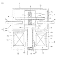
- Fig. 1 is a sectional view showing one example of a case in which a contact device of the invention is applied to an electromagnetic contactor acting as an electromagnetic switch.
- 1 is a contact device, and an electromagnetic device 2 is provided on the lower surface side of the contact device 1.
- the contact device 1 has an arc extinguishing chamber receptacle 3, which is, for example, an airtight receptacle wherein an insulation process has been carried out on a non-magnetic body and on an insulator or inner wall, and a contact mechanism 4 is provided inside the arc extinguishing chamber receptacle 3.
- the arc extinguishing chamber receptacle 3 is configured of a bottomed tubular body 3a, whose lower end surface is opened, and a bottom plate portion 3b that closes off the lower end surface of the bottomed tubular body 3a.
- An insertion hole 3c through which is inserted a shaft portion 13a of a movable plunger 13, to be described hereafter, is formed in a central portion of the bottom plate portion 3b.
- the contact mechanism 4 is configured of fixed contacts 4a and 4b and a movable contact 5.
- the fixed contacts 4a and 4b are fixed and supported, with inner side ends thereof separated by a predetermined distance and outer side ends thereof protruding to the exterior of the arc extinguishing chamber receptacle 3, in opposing wall surfaces of the bottomed tubular body 3a of the arc extinguishing chamber receptacle 3, as shown in Fig. 2 . Also, as shown in Fig. 1 and Fig.
- the movable contact 5 is formed in a flat plate form, and is disposed opposed to the fixed contacts 4a and 4b across a predetermined distance on the upper end side thereof, so that it can come into contact with, and separate from, the fixed contacts 4a and 4b.
- the movable contact 5 is mounted, biased downward by a contact spring 7, in a contact holder 6 fixed and supported by the movable plunger 13, to be described hereafter.
- the electromagnetic device 2 is provided on the lower surface side of the arc extinguishing chamber receptacle 3.
- the electromagnetic device 2 includes a coil bobbin 10 configured of a cylindrical portion 10a, whose axial direction is a vertical direction, and flange portions 10b and 10c protruding outward from either end of the cylindrical portion 10a.
- An exciting coil 11 is wound inside a cylindrical space bounded by the cylindrical portion 10a and flange portions 10b and 10c of the coil bobbin 10.
- a bottomed tubular body 12 whose top end is opened, is fitted into the inner peripheral surface of the cylindrical portion 10a of the coil bobbin 10, and the movable plunger 13, made of a magnetic body, is guided so as to be freely movable vertically inside the bottomed tubular body 12.
- the movable plunger 13 is configured in a T-form of a shaft portion 13a, inserted into the bottomed tubular body 12, and a flat plate portion 13b, extending in left and right directions, fixed to an end portion of the shaft portion 13a protruding into the arc extinguishing chamber receptacle 3.
- a return spring 14 is inserted between the lower end surface of the shaft portion 13a of the movable plunger 13 and the bottom surface of the bottomed tubular body 12, and the movable plunger 13 is biased upward by the return spring 14. Then, an upper position, that is, an opened position, of the movable plunger 13 is regulated by the flat plate portion 13b coming into contact with a first magnetic yoke, to be described hereafter. Also, a second magnetic yoke 15 is disposed on the outer peripheral side of the coil bobbin 10.
- the second magnetic yoke 15 includes a suction yoke portion 15A, which generates an electromagnetic suction force that suctions the movable plunger 13, against the force of the return spring 14, and an extension yoke portion 15B which, coupled to the suction yoke portion 15A, extends to the back surface of a permanent magnet, to be described hereafter.
- the suction yoke portion 15A includes an inner tubular portion 15a opposing the lower end side of the shaft portion 13a of the movable plunger 13 across the bottomed tubular body 12, a bottom plate portion 15b that covers the bottom surface of the coil bobbin 10 in conjunction with the lower end surface of the inner tubular portion 15a, an outer tubular portion 15c that, extending upward from the outer peripheral edge of the bottom plate portion 15b, covers the outer peripheral surface of the coil bobbin 10, and an upper plate portion 15d that, extending inward from the upper end of the outer tubular portion 15c, covers the upper surface if the coil bobbin 10.
- the extension yoke portion 15B is configured of extension plate portions 15e and 15f, which extend from opposing outer peripheral edges of the upper plate portion 15d of the suction yoke portion 15A to the outer surfaces of permanent magnets 16a and 16b, to be described hereafter.
- the permanent magnets 16a and 16b of a flattened cuboid form having a width virtually equivalent to the length in the longitudinal direction of the movable contact 5, are fixed using an adhesive, or the like, in positions opposing the movable contact 5 on either side of the outer peripheral surface of the arc extinguishing chamber receptacle 3 of the contact device 1.
- Each of the permanent magnets 16a and 16b is magnetized in such a way that the inner surface side in contact with the arc extinguishing chamber receptacle 3 is the north pole, while the outer surface side is the south pole.
- first magnetic yokes 17a and 17b are disposed in opposed positions between the pair of fixed contacts 4a and 4b on the inner peripheral surface of the arc extinguishing chamber receptacle 3 opposing the permanent magnets 16a and 16b.
- Each of the first magnetic yokes 17a and 17b is configured in a sectional L-form of a vertical plate portion 17c, fixed to the inner wall of the arc extinguishing chamber receptacle 3, and a horizontal plate portion 17d extending inward from the lower end of the vertical plate portion 17c.
- the horizontal plate portion 17d is extended to a position such that the inner end thereof opposes the fixed contacts 4a and 4b while maintaining a predetermined interval, and is in contact with the upper surface of the previously described flat plate portion 13b of the movable plunger 13.
- the lower surface of the horizontal plate portion 17d is set so that, in a condition in which the flat plate portion 13b of the movable plunger 13 is in the opened position wherein it is in contact, the upper surface of the flat plate portion 13b is in a position separated by a predetermined distance from the fixed contacts 4a and 4b.
- the movable contact 5 is separated from the fixed contacts 4a and 4b by in the region of, for example, 2mm upward, as shown in Fig. 2 , the contact device 1 is in an opened condition, and power supplied to the one fixed contact 4a is not supplied to the fixed contact 4b, resulting in a power shutoff condition.
- a magnetic path La indicated by the dashed dotted line in Fig. 1 is formed. That is, there is formed a magnetic circuit wherein a magnetic flux output from the permanent magnet 16a returns to the permanent magnet 16a via the first magnetic yoke 17a, the movable plunger 13, and the inner tubular portion 15a, bottom plate portion 15b, outer tubular portion 15c, and extension plate portion 15e of the second magnetic yoke 15.
- the flat plate portion 13b of the movable plunger 13 is suctioned by the first magnetic yokes 17a and 17b. Consequently, the movable plunger 13 is pressed against the horizontal plate portions 17d of the first magnetic yokes 17a and 17b by two forces - the suction force of the first magnetic yokes 17a and 17b and the biasing force of the return spring 14. Because of this, as the movable plunger 13 does not separate from the first magnetic yokes 17a and 17b even in the event that vibration or an impact force is introduced into the electromagnetic contactor from the exterior, it is possible to improve vibration and impact resistance performance without increasing the biasing force of the return spring 14.
- the movable plunger 13 descends against the force of the return spring 14, in accordance with which the movable contact 5 held in the contact holder 6 descends, and is brought into contact with the fixed contacts 4a and 4b at a predetermined contact pressure applied by the contact spring 7. Because of this, the space between the fixed contacts 4a and 4b is brought into a condition of continuity by the movable contact 5, and the contact device 1 is in a closed condition.
- the magnetic flux ceases to flow through the magnetic circuit in the suction yoke portion 15A of the second magnetic yoke 15 of the electromagnetic device 2, and the electromagnetic suction force exerted by the upper plate portion 15d of the second magnetic yoke 15 is extinguished. Because of this, the movable plunger 13 is returned by the biasing force of the return spring 14 to the opened position wherein the movable plunger 13 is in contact with the first magnetic yokes 17a and 17b. Because of this, the movable contact 5 moves upward, separating from the fixed contacts 4a and 4b, and the contact device 1 returns to the opened position.
- the first magnetic yokes 17a and 17b are disposed between the fixed contacts 4a and 4b, there is no effect on the function whereby an arc generated between the movable contact 5 and fixed contacts 4a and 4b at an opening time is extinguished by the permanent magnets 16a and 16b, and it is possible to improve vibration and impact resistance performance while fulfilling a reliable arc extinguishing function.
- the permanent magnets 16a and 16b are formed in one flattened cuboid but, not being limited to this, they may also be formed divided into two portions or more. Furthermore, in the embodiment, a description has been given of a case in which the invention is applied to an electromagnetic contactor but, not being limited to this, it is also possible to apply the invention to another electromagnetic switch, such as an electromagnetic relay.
- the invention provides an electromagnetic switch wherein there is formed a magnetic circuit from a permanent magnet, returning to the permanent magnet via a movable plunger, an electromagnetic suction force that suppresses vibration of the movable plunger is generated acting on the movable plunger, and it is possible to improve vibration and impact resistance performance without increasing return biasing force.
Abstract
Description
- The present invention relates to an electromagnetic switch including a contact device having fixed contacts and a movable contact inserted in a current path, and an electromagnet that drives the movable contact.
- There are proposed various mechanisms that, in an electromagnetic switch, such as an electromagnetic relay or electromagnetic contactor, that carries out an opening and closing of a current path, extinguish an arc generated at an opening time when a movable contact is caused to separate from a fixed contact in order to cut off current, thus obtaining an opened condition from a closed condition of a contact mechanism wherein the fixed contact and movable contact are in contact.
- For example, there is proposed an electromagnetic relay having a configuration including a pair of fixed contacts disposed separated by a predetermined distance, a movable contact disposed so that it can come into contact with, and separate from, the pair of fixed contacts, and an electromagnetic block having a movable iron core that drives the movable contact, wherein U-form magnetic holding members are disposed on the outer side of a sealing receptacle opposing either side surface side of positions in which the fixed contacts and movable contact are opposed, and two sets of pairs of permanent magnets for expediting arc extinguishing by drawing out the arc using magnetic force are disposed on the inner side of the magnetic holding members (for example, refer to Patent Document 1).
-
- Patent Document 1:
JP-A-2010-10057 - In the heretofore known example described in
Patent Document 1, by a pair of permanent magnets being disposed opposed in each position in which the pair of fixed contacts and movable contact are opposed, the extinguishing of an arc generated at an opening time when the movable contact is caused to separate from the pair of fixed contacts is expedited by the arc being drawn out using the magnetic force of the permanent magnets. - However, in a case in which a movable contact is disposed so that it can come into contact with, and separate from, a pair of fixed contacts separated by a predetermined distance, as in the heretofore known example described in
Patent Document 1, there is a demand for improvement in vibration and impact resistance performance at a contact mechanism opening time when the movable contact is separated from the pair of fixed contacts. Heretofore, in order to improve the vibration and impact resistance performance, the biasing force of a return coil spring provided in a movable iron core that holds the movable contact has been increased, thus suppressing the vibration of the movable iron core. - However, although it is possible to improve the vibration and impact resistance performance when increasing the biasing force of the return coil spring, it is necessary that the movable iron core can move against the biasing force of the return coil spring at a contact mechanism closing time, and thus necessary to increase electromagnetic suction force generated in an electromagnetic block, and there is an unsolved problem in that this leads to an increase in size of the electromagnetic block, and an increase in power consumption for exciting an exciting coil.
Therefore, the invention, having been contrived focusing on the unsolved problem of the heretofore known example, has an object of providing an electromagnetic switch wherein it is possible to improve vibration and impact resistance performance without increasing return biasing force. - In order to achieve the heretofore described object, a first aspect of an electromagnetic switch according to the invention includes a contact device having a pair of fixed contacts fixed maintaining a predetermined interval inside an arc extinguishing chamber receptacle and a movable contact disposed so that it can come into contact with, and separate from, the pair of fixed contacts, and an electromagnetic device having a movable plunger that can move between an opened position wherein the movable contact is caused to separate from the fixed contacts and a closed position wherein the movable contact is brought into contact with the fixed contacts and further depressed. Then, permanent magnets, which extinguish an arc generated at an opening time when the movable contact separates from the fixed contacts from a condition in which the movable contact is in the closed position wherein it is in contact with the fixed contacts, are provided on the arc extinguishing chamber receptacle and, in a condition in which the movable plunger is in the opened position, there is formed a magnetic circuit from the permanent magnets, returning to the permanent magnets via the movable plunger.
- According to this configuration, as the extinguishing of an arc generated at a contact mechanism opening time is carried out by the permanent magnets, and a magnetic circuit from the permanent magnets, returning to the permanent magnets via the movable plunger, is formed when the contact mechanism is opened, the movable plunger is suctioned by the magnetic force of the magnetic circuit, and it is possible to improve vibration and impact resistance performance without increasing the biasing force of a return spring.
Also, a second aspect of the electromagnetic switch according to the invention is such that the permanent magnets are disposed opposing the movable contact in positions perpendicular to the longitudinal direction of the movable contact on the outer side of opposing side walls of the arc extinguishing chamber receptacle. - According to this configuration, as the permanent magnets are disposed in positions opposing the movable contact, it is possible to effectively draw out and extinguish an arc generated at an opening time when the movable contact separates from the pair of fixed contacts.
Also, a third aspect of the electromagnetic switch according to the invention is such that the magnetic circuit includes first magnetic yokes, disposed opposed between the pair of fixed contacts on the inner surface side of the arc extinguishing chamber receptacle opposing the permanent magnets, that are in contact with the movable plunger in the opened position, and second magnetic yokes that oppose a region of the movable plunger on the side opposite to the region in contact with the first magnetic yoke and are in contact with the back surface sides of the permanent magnets. - According to this configuration, it is possible to configure a magnetic circuit passing from the permanent magnets via the first magnetic yokes and movable plunger, and returning to the permanent magnets from the second magnetic yokes, at a contact mechanism opening time, and thus possible to improve the vibration and impact resistance performance of the movable plunger by generating in the first magnetic yokes an electromagnetic suction force that suctions the movable plunger. Herein, as a sufficient gap is provided between the movable plunger and first magnetic yokes when the arc is drawn out and extinguished, there is no effect on the function whereby an arc generated at an opening time is extinguished by the permanent magnets.
- According to the invention, as a magnetic circuit from the permanent magnets, returning to the permanent magnets via the movable plunger, is formed in a condition in which the movable plunger is in the opened position, an advantage is obtained in that an electromagnetic suction force that suppresses vibration of the movable plunger is generated acting on the movable plunger, and it is thus possible to improve vibration and impact resistance performance without increasing return biasing force.
-
- [
Fig. 1] Fig. 1 is a sectional view showing one embodiment of a case in which the invention is applied to an electromagnetic contactor. - [
Fig. 2] Fig. 2 is a sectional view along a line A-A ofFig. 1 . - Hereafter, a description will be given, based on the drawings, of an embodiment of the invention.
Fig. 1 is a sectional view showing one example of a case in which a contact device of the invention is applied to an electromagnetic contactor acting as an electromagnetic switch. InFig. 1, 1 is a contact device, and anelectromagnetic device 2 is provided on the lower surface side of thecontact device 1.
Thecontact device 1 has an arcextinguishing chamber receptacle 3, which is, for example, an airtight receptacle wherein an insulation process has been carried out on a non-magnetic body and on an insulator or inner wall, and acontact mechanism 4 is provided inside the arcextinguishing chamber receptacle 3. The arcextinguishing chamber receptacle 3 is configured of a bottomedtubular body 3a, whose lower end surface is opened, and abottom plate portion 3b that closes off the lower end surface of the bottomedtubular body 3a. Aninsertion hole 3c, through which is inserted ashaft portion 13a of amovable plunger 13, to be described hereafter, is formed in a central portion of thebottom plate portion 3b. - The
contact mechanism 4 is configured offixed contacts movable contact 5. Thefixed contacts extinguishing chamber receptacle 3, in opposing wall surfaces of the bottomedtubular body 3a of the arc extinguishingchamber receptacle 3, as shown inFig. 2 .
Also, as shown inFig. 1 andFig. 2 , themovable contact 5 is formed in a flat plate form, and is disposed opposed to thefixed contacts fixed contacts movable contact 5 is mounted, biased downward by acontact spring 7, in acontact holder 6 fixed and supported by themovable plunger 13, to be described hereafter. - Also, the
electromagnetic device 2 is provided on the lower surface side of the arcextinguishing chamber receptacle 3. Theelectromagnetic device 2 includes acoil bobbin 10 configured of acylindrical portion 10a, whose axial direction is a vertical direction, andflange portions cylindrical portion 10a. Anexciting coil 11 is wound inside a cylindrical space bounded by thecylindrical portion 10a andflange portions coil bobbin 10. - Also, a bottomed
tubular body 12, whose top end is opened, is fitted into the inner peripheral surface of thecylindrical portion 10a of thecoil bobbin 10, and themovable plunger 13, made of a magnetic body, is guided so as to be freely movable vertically inside the bottomedtubular body 12.
Themovable plunger 13 is configured in a T-form of ashaft portion 13a, inserted into the bottomedtubular body 12, and aflat plate portion 13b, extending in left and right directions, fixed to an end portion of theshaft portion 13a protruding into the arcextinguishing chamber receptacle 3. Thecontact holder 6, which holds themovable contact 5 in a central portion of the upper surface, is fixed and supported in theflat plate portion 13b of themovable plunger 13. - Also, a
return spring 14 is inserted between the lower end surface of theshaft portion 13a of themovable plunger 13 and the bottom surface of the bottomedtubular body 12, and themovable plunger 13 is biased upward by thereturn spring 14. Then, an upper position, that is, an opened position, of themovable plunger 13 is regulated by theflat plate portion 13b coming into contact with a first magnetic yoke, to be described hereafter.
Also, a secondmagnetic yoke 15 is disposed on the outer peripheral side of thecoil bobbin 10. The secondmagnetic yoke 15 includes asuction yoke portion 15A, which generates an electromagnetic suction force that suctions themovable plunger 13, against the force of thereturn spring 14, and anextension yoke portion 15B which, coupled to thesuction yoke portion 15A, extends to the back surface of a permanent magnet, to be described hereafter. - The
suction yoke portion 15A includes an innertubular portion 15a opposing the lower end side of theshaft portion 13a of themovable plunger 13 across the bottomedtubular body 12, abottom plate portion 15b that covers the bottom surface of thecoil bobbin 10 in conjunction with the lower end surface of the innertubular portion 15a, an outertubular portion 15c that, extending upward from the outer peripheral edge of thebottom plate portion 15b, covers the outer peripheral surface of thecoil bobbin 10, and anupper plate portion 15d that, extending inward from the upper end of the outertubular portion 15c, covers the upper surface if thecoil bobbin 10.
Also, theextension yoke portion 15B, as shown inFig. 1 , is configured ofextension plate portions upper plate portion 15d of thesuction yoke portion 15A to the outer surfaces ofpermanent magnets - Meanwhile, the
permanent magnets movable contact 5, are fixed using an adhesive, or the like, in positions opposing themovable contact 5 on either side of the outer peripheral surface of the arcextinguishing chamber receptacle 3 of thecontact device 1. Each of thepermanent magnets extinguishing chamber receptacle 3 is the north pole, while the outer surface side is the south pole.
Also, firstmagnetic yokes fixed contacts extinguishing chamber receptacle 3 opposing thepermanent magnets - Each of the first
magnetic yokes vertical plate portion 17c, fixed to the inner wall of the arcextinguishing chamber receptacle 3, and ahorizontal plate portion 17d extending inward from the lower end of thevertical plate portion 17c. Herein, thehorizontal plate portion 17d is extended to a position such that the inner end thereof opposes thefixed contacts flat plate portion 13b of themovable plunger 13. Furthermore, the lower surface of thehorizontal plate portion 17d is set so that, in a condition in which theflat plate portion 13b of themovable plunger 13 is in the opened position wherein it is in contact, the upper surface of theflat plate portion 13b is in a position separated by a predetermined distance from thefixed contacts - Next, a description will be given of an operation of the embodiment.
Now, when the exciting coil of theelectromagnetic device 2 is in a non-conductive condition in which no current is supplied, no magnetic flux flows to thesuction yoke portion 15A of the secondmagnetic yoke 15, and a condition is such that no electromagnetic suction force suctioning themovable plunger 13 is generated.
Because of this, themovable plunger 13 is biased upward by thereturn spring 14, and the upper end of theflat plate portion 13b is in the opened position wherein it is in contact with the lower surface of thehorizontal plate portions 17d of the firstmagnetic yokes - In the condition in which the
movable plunger 13 is in the opened position, themovable contact 5 is separated from thefixed contacts Fig. 2 , thecontact device 1 is in an opened condition, and power supplied to the onefixed contact 4a is not supplied to the fixedcontact 4b, resulting in a power shutoff condition. - As the
flat plate portion 13b of themovable plunger 13 is in contact with the lower surface of thehorizontal plate portions 17d of the firstmagnetic yokes contact mechanism 4 is in the opened condition, a magnetic path La indicated by the dashed dotted line inFig. 1 is formed. That is, there is formed a magnetic circuit wherein a magnetic flux output from thepermanent magnet 16a returns to thepermanent magnet 16a via the firstmagnetic yoke 17a, themovable plunger 13, and the innertubular portion 15a,bottom plate portion 15b, outertubular portion 15c, andextension plate portion 15e of the secondmagnetic yoke 15. - In the same way, there is formed a magnetic circuit wherein a magnetic flux output from the
permanent magnet 16b returns to thepermanent magnet 16b via the firstmagnetic yoke 17b, themovable plunger 13, and the innertubular portion 15a,bottom plate portion 15b, outertubular portion 15c, andextension plate portion 15f of the secondmagnetic yoke 15. - Because of this, the
flat plate portion 13b of themovable plunger 13 is suctioned by the firstmagnetic yokes movable plunger 13 is pressed against thehorizontal plate portions 17d of the firstmagnetic yokes magnetic yokes return spring 14. Because of this, as themovable plunger 13 does not separate from the firstmagnetic yokes return spring 14. - When energizing the
exciting coil 11 with thecontact device 1 in the opened condition, there is formed a magnetic circuit Lb from theflat plate portion 13b of themovable plunger 13, returning to theshaft portion 13a of themovable plunger 13 via the upper plate portion 10d, outertubular portion 15c,bottom plate portion 15b, and innertubular portion 15a of thesuction yoke portion 15A of the second magnetic yoke, and a magnetic flux flows through themovable plunger 13 in a direction the reverse of that in the magnetic circuit La. Because of this, theflat plate portion 13b of themovable plunger 13 is suctioned to theupper plate portion 15d in thesuction yoke portion 15A of the secondmagnetic yoke 15. As a result of this, themovable plunger 13 descends against the force of thereturn spring 14, in accordance with which themovable contact 5 held in thecontact holder 6 descends, and is brought into contact with the fixedcontacts contact spring 7. Because of this, the space between the fixedcontacts movable contact 5, and thecontact device 1 is in a closed condition. - When stopping the energizing of the
exciting coil 11 with thecontact device 1 in the closed condition, the magnetic flux ceases to flow through the magnetic circuit in thesuction yoke portion 15A of the secondmagnetic yoke 15 of theelectromagnetic device 2, and the electromagnetic suction force exerted by theupper plate portion 15d of the secondmagnetic yoke 15 is extinguished. Because of this, themovable plunger 13 is returned by the biasing force of thereturn spring 14 to the opened position wherein themovable plunger 13 is in contact with the firstmagnetic yokes movable contact 5 moves upward, separating from the fixedcontacts contact device 1 returns to the opened position. - At an opening time when the
movable contact 5 separates from the fixedcontacts movable contact 5 and fixedcontacts permanent magnets permanent magnets - In this way, according to the embodiment, utilizing the
permanent magnets contact mechanism 4 of thecontact device 1, there is formed, in a condition in which themovable plunger 13 is in the opened position, a magnetic circuit wherein magnetic fluxes output from thepermanent magnets permanent magnets magnetic yokes movable plunger 13, and thesuction yoke portion 15A andextension yoke portion 15B of the secondmagnetic yoke 15. Because of this, it is possible to cause an electromagnetic suction force that suctions theflat plate portion 13b of themovable plunger 13 to be generated in the firstmagnetic yokes return spring 14, it is possible to cause the firstmagnetic yokes movable plunger 13, and thus possible to improve vibration and impact resistance performance without increasing the biasing force of thereturn spring 14. Because of this, it is possible to improve vibration and impact resistance performance without the size of the configuration of theelectromagnetic device 2 increasing, and without power consumption increasing. - Moreover, as the first
magnetic yokes contacts movable contact 5 and fixedcontacts permanent magnets
In the embodiment, a description has been given of a case in which thepermanent magnets chamber receptacle 3 but, not being limited to this, a pocket portion in which thepermanent magnets chamber receptacle 3. In this case, it is sufficient that the firstmagnetic yokes - Also, in the embodiment, a description has been given of a case in which the
permanent magnets
Furthermore, in the embodiment, a description has been given of a case in which the invention is applied to an electromagnetic contactor but, not being limited to this, it is also possible to apply the invention to another electromagnetic switch, such as an electromagnetic relay. - The invention provides an electromagnetic switch wherein there is formed a magnetic circuit from a permanent magnet, returning to the permanent magnet via a movable plunger, an electromagnetic suction force that suppresses vibration of the movable plunger is generated acting on the movable plunger, and it is possible to improve vibration and impact resistance performance without increasing return biasing force. Description of Reference Numerals and Signs
- 1 ··· Contact device, 2 ··· Electromagnetic device, 3 ··· Arc extinguishing chamber receptacle, 3a ··· Bottomed tubular body, 3b ··· Bottom plate portion, 4 ··· Contact mechanism, 4a, 4b ··· Fixed contact, 5 ··· Movable contact, 6 ··· Contact holder, 7 ··· Contact spring, 10 ··· Coil bobbin, 11 ··· Exciting coil, 12 ··· Bottomed tubular body, 13 ··· Movable plunger, 13a ··· Shaft portion, 13b ··· Flat plate portion, 14 ··· Return spring, 15 ··· Second magnetic yoke, 15A ··· Suction yoke portion, 15B ··· Extension yoke portion, 15a ··· Inner tubular portion, 15b ··· Bottom plate portion, 15c ··· Outer tubular portion, 15d ··· Upper plate portion, 15e, 15f ··· Extension plate portion, 16a, 16b ··· Permanent magnet, 17a, 17b ··· First magnetic yoke
Claims (3)
- An electromagnetic switch, characterized by comprising:a contact device having a pair of fixed contacts fixed maintaining a predetermined interval inside an arc extinguishing chamber receptacle and a movable contact disposed so that it can come into contact with, and separate from, the pair of fixed contacts; andan electromagnetic device having a movable plunger that can move between an opened position wherein the movable contact is caused to separate from the fixed contacts and a closed position wherein the movable contact is brought into contact with the fixed contacts and pressed down, whereinpermanent magnets, which extinguish an arc generated at an opening time when the movable contact separates from the fixed contacts from a condition in which the movable contact is in the closed position wherein it is in contact with the fixed contacts, are provided on the arc extinguishing chamber receptacle, andin a condition in which the movable plunger is in the opened position, there is formed a magnetic circuit from the permanent magnets, returning to the permanent magnets via the movable plunger.
- The electromagnetic switch according to claim 1, characterized in that the permanent magnets are disposed opposing the movable contact in positions perpendicular to the longitudinal direction of the movable contact on the outer side of opposing side walls of the arc extinguishing chamber receptacle.
- The electromagnetic switch according to claim 1 or 2, characterized in that the magnetic circuit includes first magnetic yokes, disposed opposed between the pair of fixed contacts on the inner surface side of the arc extinguishing chamber receptacle opposing the permanent magnets, that are in contact with the movable plunger in the opened position, and second magnetic yokes that oppose a region of the movable plunger on the side opposite to the region in contact with the first magnetic yoke and are in contact with the back surface sides of the permanent magnets.
Applications Claiming Priority (2)
| Application Number | Priority Date | Filing Date | Title |
|---|---|---|---|
| JP2010194463A JP5307779B2 (en) | 2010-08-31 | 2010-08-31 | electromagnetic switch |
| PCT/JP2011/003381 WO2012029218A1 (en) | 2010-08-31 | 2011-06-14 | Electromagnetic switch |
Publications (2)
| Publication Number | Publication Date |
|---|---|
| EP2557582A1 true EP2557582A1 (en) | 2013-02-13 |
| EP2557582A4 EP2557582A4 (en) | 2014-05-21 |
Family
ID=45772345
Family Applications (1)
| Application Number | Title | Priority Date | Filing Date |
|---|---|---|---|
| EP11821243.0A Withdrawn EP2557582A4 (en) | 2010-08-31 | 2011-06-14 | Electromagnetic switch |
Country Status (6)
| Country | Link |
|---|---|
| US (1) | US8937518B2 (en) |
| EP (1) | EP2557582A4 (en) |
| JP (1) | JP5307779B2 (en) |
| KR (1) | KR20140003390A (en) |
| CN (1) | CN103155082B (en) |
| WO (1) | WO2012029218A1 (en) |
Cited By (5)
| Publication number | Priority date | Publication date | Assignee | Title |
|---|---|---|---|---|
| CN103247479A (en) * | 2013-04-18 | 2013-08-14 | 戴丁志 | Electromagnetic type power master switch |
| CN103268840A (en) * | 2013-04-18 | 2013-08-28 | 戴丁志 | Electromagnetic power main switch |
| US9484173B2 (en) | 2012-11-13 | 2016-11-01 | Fuji Electric Fa Components & Systems Co., Ltd. | Electromagnetic switch with increased magnetic flux density |
| US9564279B2 (en) | 2012-11-09 | 2017-02-07 | Fuji Electric Fa Components & Systems Co., Ltd. | Electromagnetic switch having magnetic yoke with slits |
| WO2020148634A1 (en) * | 2019-01-18 | 2020-07-23 | Te Connectivity Corporation | Contactor with arc suppressor |
Families Citing this family (20)
| Publication number | Priority date | Publication date | Assignee | Title |
|---|---|---|---|---|
| JP5727860B2 (en) * | 2011-05-19 | 2015-06-03 | 富士電機機器制御株式会社 | Magnetic contactor |
| JP5965197B2 (en) | 2012-04-13 | 2016-08-03 | 富士電機機器制御株式会社 | Switch |
| JP5938745B2 (en) * | 2012-07-06 | 2016-06-22 | パナソニックIpマネジメント株式会社 | Contact device and electromagnetic relay equipped with the contact device |
| DE102013210195A1 (en) * | 2013-05-31 | 2014-12-04 | Tyco Electronics Amp Gmbh | Arrangement for an electrical switching element and switching element |
| JP6202943B2 (en) * | 2013-08-26 | 2017-09-27 | 富士通コンポーネント株式会社 | Electromagnetic relay |
| JP6406596B2 (en) * | 2014-05-12 | 2018-10-17 | パナソニックIpマネジメント株式会社 | Contact device |
| CN104199563B (en) * | 2014-09-23 | 2017-03-22 | 陈浩宇 | Electromagnetic keyboard |
| JP6274229B2 (en) * | 2016-01-27 | 2018-02-07 | 富士電機機器制御株式会社 | Contact device and electromagnetic contactor using the same |
| JP6536472B2 (en) * | 2016-04-28 | 2019-07-03 | 株式会社デンソー | solenoid |
| CN106252162A (en) * | 2016-08-01 | 2016-12-21 | 厦门宏发电力电器有限公司 | A kind of arc extinguishing magnetic circuit and DC relay thereof |
| CN106229179B (en) * | 2016-08-03 | 2018-08-03 | 太仓美宅姬娱乐传媒有限公司 | A kind of electromagnetic switch using shift fork extinguishing arc |
| US11205546B2 (en) * | 2017-07-26 | 2021-12-21 | Mitsubishi Electric Corporation | Switch |
| US10950402B2 (en) * | 2017-10-17 | 2021-03-16 | Solarbos, Inc. | Electrical contactor |
| JP7068929B2 (en) | 2018-05-31 | 2022-05-17 | 富士通コンポーネント株式会社 | Electromagnetic relay |
| JP7293598B2 (en) * | 2018-10-10 | 2023-06-20 | オムロン株式会社 | electromagnetic relay |
| JP7115303B2 (en) * | 2018-12-28 | 2022-08-09 | オムロン株式会社 | electromagnetic relay |
| JP2021044211A (en) * | 2019-09-13 | 2021-03-18 | オムロン株式会社 | Electromagnetic relay |
| US11908648B2 (en) * | 2020-01-23 | 2024-02-20 | Mitsubishi Electric Corporation | Switch configured to form magnetic fields relative to contact points |
| CN111681341A (en) * | 2020-05-22 | 2020-09-18 | 深圳市多度科技有限公司 | Control method of entrance guard lock and entrance guard lock control circuit |
| CN114156122A (en) * | 2021-12-15 | 2022-03-08 | 正勤电气(沈阳)有限公司 | Separated magnetic circuit type bistable permanent magnet operating mechanism |
Citations (4)
| Publication number | Priority date | Publication date | Assignee | Title |
|---|---|---|---|---|
| US20060050466A1 (en) * | 2003-07-02 | 2006-03-09 | Matsushita Electric Works, Ltd. | Electromagnetic switching device |
| WO2006069970A1 (en) * | 2004-12-23 | 2006-07-06 | Siemens Aktiengesellschaft | Method and device for the safe operation of a switching device |
| EP2141723A2 (en) * | 2008-06-30 | 2010-01-06 | Omron Corporation | Electromagnet device |
| JP2010010057A (en) * | 2008-06-30 | 2010-01-14 | Omron Corp | Electromagnetic relay |
Family Cites Families (8)
| Publication number | Priority date | Publication date | Assignee | Title |
|---|---|---|---|---|
| EP0179912B1 (en) * | 1984-05-01 | 1990-10-24 | Mitsubishi Denki Kabushiki Kaisha | Switch |
| JPH088048B2 (en) * | 1989-09-18 | 1996-01-29 | 三菱電機株式会社 | Current limiting device |
| JPH04341721A (en) * | 1990-07-24 | 1992-11-27 | Fuji Electric Co Ltd | Electromagnetic switch |
| JP4265725B2 (en) * | 1998-12-28 | 2009-05-20 | 三菱電機株式会社 | Current limiting device and circuit breaker having current limiting function |
| CN1323410C (en) * | 1999-10-14 | 2007-06-27 | 松下电工株式会社 | Contactor |
| JP2010118206A (en) | 2008-11-12 | 2010-05-27 | Kyoritsu Keiki Co Ltd | Electromagnetic contactor |
| CN201562631U (en) | 2009-11-03 | 2010-08-25 | 泰科电子(深圳)有限公司 | contactor |
| JP5385877B2 (en) * | 2010-08-31 | 2014-01-08 | 富士電機機器制御株式会社 | electromagnetic switch |
-
2010
- 2010-08-31 JP JP2010194463A patent/JP5307779B2/en not_active Expired - Fee Related
-
2011
- 2011-06-14 KR KR1020137006017A patent/KR20140003390A/en active Search and Examination
- 2011-06-14 US US13/696,929 patent/US8937518B2/en not_active Expired - Fee Related
- 2011-06-14 WO PCT/JP2011/003381 patent/WO2012029218A1/en active Application Filing
- 2011-06-14 CN CN201180027673.0A patent/CN103155082B/en not_active Expired - Fee Related
- 2011-06-14 EP EP11821243.0A patent/EP2557582A4/en not_active Withdrawn
Patent Citations (4)
| Publication number | Priority date | Publication date | Assignee | Title |
|---|---|---|---|---|
| US20060050466A1 (en) * | 2003-07-02 | 2006-03-09 | Matsushita Electric Works, Ltd. | Electromagnetic switching device |
| WO2006069970A1 (en) * | 2004-12-23 | 2006-07-06 | Siemens Aktiengesellschaft | Method and device for the safe operation of a switching device |
| EP2141723A2 (en) * | 2008-06-30 | 2010-01-06 | Omron Corporation | Electromagnet device |
| JP2010010057A (en) * | 2008-06-30 | 2010-01-14 | Omron Corp | Electromagnetic relay |
Non-Patent Citations (1)
| Title |
|---|
| See also references of WO2012029218A1 * |
Cited By (6)
| Publication number | Priority date | Publication date | Assignee | Title |
|---|---|---|---|---|
| US9564279B2 (en) | 2012-11-09 | 2017-02-07 | Fuji Electric Fa Components & Systems Co., Ltd. | Electromagnetic switch having magnetic yoke with slits |
| US9484173B2 (en) | 2012-11-13 | 2016-11-01 | Fuji Electric Fa Components & Systems Co., Ltd. | Electromagnetic switch with increased magnetic flux density |
| CN103247479A (en) * | 2013-04-18 | 2013-08-14 | 戴丁志 | Electromagnetic type power master switch |
| CN103268840A (en) * | 2013-04-18 | 2013-08-28 | 戴丁志 | Electromagnetic power main switch |
| WO2020148634A1 (en) * | 2019-01-18 | 2020-07-23 | Te Connectivity Corporation | Contactor with arc suppressor |
| US10998155B2 (en) | 2019-01-18 | 2021-05-04 | Te Connectivity Corporation | Contactor with arc suppressor |
Also Published As
| Publication number | Publication date |
|---|---|
| KR20140003390A (en) | 2014-01-09 |
| US8937518B2 (en) | 2015-01-20 |
| CN103155082A (en) | 2013-06-12 |
| JP2012054047A (en) | 2012-03-15 |
| JP5307779B2 (en) | 2013-10-02 |
| US20140176268A1 (en) | 2014-06-26 |
| CN103155082B (en) | 2015-08-19 |
| EP2557582A4 (en) | 2014-05-21 |
| WO2012029218A1 (en) | 2012-03-08 |
Similar Documents
| Publication | Publication Date | Title |
|---|---|---|
| EP2557582A1 (en) | Electromagnetic switch | |
| US20190148095A1 (en) | Contact switching device and electromagnetic relay using same | |
| JP5884034B2 (en) | Contact device | |
| US8570125B2 (en) | Electromagnetic switch | |
| CN110164725B (en) | Electromagnetic relay | |
| US8760247B2 (en) | Electromagnetic contactor | |
| EP2711962A1 (en) | Electromagnetic contactor | |
| EP2835813B1 (en) | Contact mechanism and electromagnetic relay | |
| US20150206666A1 (en) | Electromagnetic contactor | |
| JP2016201187A (en) | Electromagnetic relay | |
| JP5120162B2 (en) | Electromagnetic relay | |
| WO2022004378A1 (en) | Electromagnetic relay | |
| CN112470244A (en) | Electromagnetic relay | |
| US11784017B2 (en) | Electromagnetic relay | |
| JP2013008621A (en) | Contactor and electromagnetic switch | |
| US11450498B2 (en) | Relay | |
| JP5942276B2 (en) | Contact device | |
| US20210335565A1 (en) | Relay | |
| US11636992B2 (en) | Electromagnetic relay including fixed terminal having chamfered shape or movable contact piece having chamfered shape | |
| JP6064289B2 (en) | Contact device | |
| JP7056549B2 (en) | Electromagnetic relay | |
| KR20230146984A (en) | Electromagnetic relay | |
| CN113272929A (en) | Relay with a movable contact | |
| JP2020071993A (en) | relay | |
| KR20160114404A (en) | Magnetic contactor |
Legal Events
| Date | Code | Title | Description |
|---|---|---|---|
| PUAI | Public reference made under article 153(3) epc to a published international application that has entered the european phase |
Free format text: ORIGINAL CODE: 0009012 |
|
| 17P | Request for examination filed |
Effective date: 20121106 |
|
| AK | Designated contracting states |
Kind code of ref document: A1 Designated state(s): AL AT BE BG CH CY CZ DE DK EE ES FI FR GB GR HR HU IE IS IT LI LT LU LV MC MK MT NL NO PL PT RO RS SE SI SK SM TR |
|
| DAX | Request for extension of the european patent (deleted) | ||
| A4 | Supplementary search report drawn up and despatched |
Effective date: 20140422 |
|
| RIC1 | Information provided on ipc code assigned before grant |
Ipc: H01H 9/44 20060101ALI20140414BHEP Ipc: H01H 50/30 20060101AFI20140414BHEP |
|
| GRAP | Despatch of communication of intention to grant a patent |
Free format text: ORIGINAL CODE: EPIDOSNIGR1 |
|
| INTG | Intention to grant announced |
Effective date: 20150305 |
|
| RAP1 | Party data changed (applicant data changed or rights of an application transferred) |
Owner name: FUJI ELECTRIC FA COMPONENTS & SYSTEMS CO., LTD. Owner name: FUJI ELECTRIC CO., LTD. |
|
| RIN1 | Information on inventor provided before grant (corrected) |
Inventor name: NAKA, YASUHIRO Inventor name: SHIBA, YUJI Inventor name: YAMAMOTO, YUICHI Inventor name: SUZUKI, KENJI Inventor name: TAKAYA, KOETSU |
|
| INTG | Intention to grant announced |
Effective date: 20150310 |
|
| STAA | Information on the status of an ep patent application or granted ep patent |
Free format text: STATUS: THE APPLICATION IS DEEMED TO BE WITHDRAWN |
|
| 18D | Application deemed to be withdrawn |
Effective date: 20150721 |