WO2012026196A1 - 車両用駆動装置 - Google Patents
車両用駆動装置 Download PDFInfo
- Publication number
- WO2012026196A1 WO2012026196A1 PCT/JP2011/064314 JP2011064314W WO2012026196A1 WO 2012026196 A1 WO2012026196 A1 WO 2012026196A1 JP 2011064314 W JP2011064314 W JP 2011064314W WO 2012026196 A1 WO2012026196 A1 WO 2012026196A1
- Authority
- WO
- WIPO (PCT)
- Prior art keywords
- electric motor
- connection
- wheel
- state
- vehicle
- Prior art date
Links
Images


Classifications
-
- B—PERFORMING OPERATIONS; TRANSPORTING
- B60—VEHICLES IN GENERAL
- B60K—ARRANGEMENT OR MOUNTING OF PROPULSION UNITS OR OF TRANSMISSIONS IN VEHICLES; ARRANGEMENT OR MOUNTING OF PLURAL DIVERSE PRIME-MOVERS IN VEHICLES; AUXILIARY DRIVES FOR VEHICLES; INSTRUMENTATION OR DASHBOARDS FOR VEHICLES; ARRANGEMENTS IN CONNECTION WITH COOLING, AIR INTAKE, GAS EXHAUST OR FUEL SUPPLY OF PROPULSION UNITS IN VEHICLES
- B60K6/00—Arrangement or mounting of plural diverse prime-movers for mutual or common propulsion, e.g. hybrid propulsion systems comprising electric motors and internal combustion engines ; Control systems therefor, i.e. systems controlling two or more prime movers, or controlling one of these prime movers and any of the transmission, drive or drive units Informative references: mechanical gearings with secondary electric drive F16H3/72; arrangements for handling mechanical energy structurally associated with the dynamo-electric machine H02K7/00; machines comprising structurally interrelated motor and generator parts H02K51/00; dynamo-electric machines not otherwise provided for in H02K see H02K99/00
- B60K6/20—Arrangement or mounting of plural diverse prime-movers for mutual or common propulsion, e.g. hybrid propulsion systems comprising electric motors and internal combustion engines ; Control systems therefor, i.e. systems controlling two or more prime movers, or controlling one of these prime movers and any of the transmission, drive or drive units Informative references: mechanical gearings with secondary electric drive F16H3/72; arrangements for handling mechanical energy structurally associated with the dynamo-electric machine H02K7/00; machines comprising structurally interrelated motor and generator parts H02K51/00; dynamo-electric machines not otherwise provided for in H02K see H02K99/00 the prime-movers consisting of electric motors and internal combustion engines, e.g. HEVs
- B60K6/42—Arrangement or mounting of plural diverse prime-movers for mutual or common propulsion, e.g. hybrid propulsion systems comprising electric motors and internal combustion engines ; Control systems therefor, i.e. systems controlling two or more prime movers, or controlling one of these prime movers and any of the transmission, drive or drive units Informative references: mechanical gearings with secondary electric drive F16H3/72; arrangements for handling mechanical energy structurally associated with the dynamo-electric machine H02K7/00; machines comprising structurally interrelated motor and generator parts H02K51/00; dynamo-electric machines not otherwise provided for in H02K see H02K99/00 the prime-movers consisting of electric motors and internal combustion engines, e.g. HEVs characterised by the architecture of the hybrid electric vehicle
- B60K6/46—Series type
-
- B—PERFORMING OPERATIONS; TRANSPORTING
- B60—VEHICLES IN GENERAL
- B60W—CONJOINT CONTROL OF VEHICLE SUB-UNITS OF DIFFERENT TYPE OR DIFFERENT FUNCTION; CONTROL SYSTEMS SPECIALLY ADAPTED FOR HYBRID VEHICLES; ROAD VEHICLE DRIVE CONTROL SYSTEMS FOR PURPOSES NOT RELATED TO THE CONTROL OF A PARTICULAR SUB-UNIT
- B60W10/00—Conjoint control of vehicle sub-units of different type or different function
- B60W10/02—Conjoint control of vehicle sub-units of different type or different function including control of driveline clutches
-
- B—PERFORMING OPERATIONS; TRANSPORTING
- B60—VEHICLES IN GENERAL
- B60K—ARRANGEMENT OR MOUNTING OF PROPULSION UNITS OR OF TRANSMISSIONS IN VEHICLES; ARRANGEMENT OR MOUNTING OF PLURAL DIVERSE PRIME-MOVERS IN VEHICLES; AUXILIARY DRIVES FOR VEHICLES; INSTRUMENTATION OR DASHBOARDS FOR VEHICLES; ARRANGEMENTS IN CONNECTION WITH COOLING, AIR INTAKE, GAS EXHAUST OR FUEL SUPPLY OF PROPULSION UNITS IN VEHICLES
- B60K17/00—Arrangement or mounting of transmissions in vehicles
- B60K17/04—Arrangement or mounting of transmissions in vehicles characterised by arrangement, location, or kind of gearing
- B60K17/043—Transmission unit disposed in on near the vehicle wheel, or between the differential gear unit and the wheel
- B60K17/046—Transmission unit disposed in on near the vehicle wheel, or between the differential gear unit and the wheel with planetary gearing having orbital motion
-
- B—PERFORMING OPERATIONS; TRANSPORTING
- B60—VEHICLES IN GENERAL
- B60K—ARRANGEMENT OR MOUNTING OF PROPULSION UNITS OR OF TRANSMISSIONS IN VEHICLES; ARRANGEMENT OR MOUNTING OF PLURAL DIVERSE PRIME-MOVERS IN VEHICLES; AUXILIARY DRIVES FOR VEHICLES; INSTRUMENTATION OR DASHBOARDS FOR VEHICLES; ARRANGEMENTS IN CONNECTION WITH COOLING, AIR INTAKE, GAS EXHAUST OR FUEL SUPPLY OF PROPULSION UNITS IN VEHICLES
- B60K17/00—Arrangement or mounting of transmissions in vehicles
- B60K17/34—Arrangement or mounting of transmissions in vehicles for driving both front and rear wheels, e.g. four wheel drive vehicles
- B60K17/356—Arrangement or mounting of transmissions in vehicles for driving both front and rear wheels, e.g. four wheel drive vehicles having fluid or electric motor, for driving one or more wheels
-
- B—PERFORMING OPERATIONS; TRANSPORTING
- B60—VEHICLES IN GENERAL
- B60K—ARRANGEMENT OR MOUNTING OF PROPULSION UNITS OR OF TRANSMISSIONS IN VEHICLES; ARRANGEMENT OR MOUNTING OF PLURAL DIVERSE PRIME-MOVERS IN VEHICLES; AUXILIARY DRIVES FOR VEHICLES; INSTRUMENTATION OR DASHBOARDS FOR VEHICLES; ARRANGEMENTS IN CONNECTION WITH COOLING, AIR INTAKE, GAS EXHAUST OR FUEL SUPPLY OF PROPULSION UNITS IN VEHICLES
- B60K6/00—Arrangement or mounting of plural diverse prime-movers for mutual or common propulsion, e.g. hybrid propulsion systems comprising electric motors and internal combustion engines ; Control systems therefor, i.e. systems controlling two or more prime movers, or controlling one of these prime movers and any of the transmission, drive or drive units Informative references: mechanical gearings with secondary electric drive F16H3/72; arrangements for handling mechanical energy structurally associated with the dynamo-electric machine H02K7/00; machines comprising structurally interrelated motor and generator parts H02K51/00; dynamo-electric machines not otherwise provided for in H02K see H02K99/00
- B60K6/20—Arrangement or mounting of plural diverse prime-movers for mutual or common propulsion, e.g. hybrid propulsion systems comprising electric motors and internal combustion engines ; Control systems therefor, i.e. systems controlling two or more prime movers, or controlling one of these prime movers and any of the transmission, drive or drive units Informative references: mechanical gearings with secondary electric drive F16H3/72; arrangements for handling mechanical energy structurally associated with the dynamo-electric machine H02K7/00; machines comprising structurally interrelated motor and generator parts H02K51/00; dynamo-electric machines not otherwise provided for in H02K see H02K99/00 the prime-movers consisting of electric motors and internal combustion engines, e.g. HEVs
- B60K6/50—Architecture of the driveline characterised by arrangement or kind of transmission units
- B60K6/52—Driving a plurality of drive axles, e.g. four-wheel drive
-
- B—PERFORMING OPERATIONS; TRANSPORTING
- B60—VEHICLES IN GENERAL
- B60K—ARRANGEMENT OR MOUNTING OF PROPULSION UNITS OR OF TRANSMISSIONS IN VEHICLES; ARRANGEMENT OR MOUNTING OF PLURAL DIVERSE PRIME-MOVERS IN VEHICLES; AUXILIARY DRIVES FOR VEHICLES; INSTRUMENTATION OR DASHBOARDS FOR VEHICLES; ARRANGEMENTS IN CONNECTION WITH COOLING, AIR INTAKE, GAS EXHAUST OR FUEL SUPPLY OF PROPULSION UNITS IN VEHICLES
- B60K7/00—Disposition of motor in, or adjacent to, traction wheel
- B60K7/0007—Disposition of motor in, or adjacent to, traction wheel the motor being electric
-
- B—PERFORMING OPERATIONS; TRANSPORTING
- B60—VEHICLES IN GENERAL
- B60W—CONJOINT CONTROL OF VEHICLE SUB-UNITS OF DIFFERENT TYPE OR DIFFERENT FUNCTION; CONTROL SYSTEMS SPECIALLY ADAPTED FOR HYBRID VEHICLES; ROAD VEHICLE DRIVE CONTROL SYSTEMS FOR PURPOSES NOT RELATED TO THE CONTROL OF A PARTICULAR SUB-UNIT
- B60W20/00—Control systems specially adapted for hybrid vehicles
- B60W20/10—Controlling the power contribution of each of the prime movers to meet required power demand
- B60W20/13—Controlling the power contribution of each of the prime movers to meet required power demand in order to stay within battery power input or output limits; in order to prevent overcharging or battery depletion
- B60W20/14—Controlling the power contribution of each of the prime movers to meet required power demand in order to stay within battery power input or output limits; in order to prevent overcharging or battery depletion in conjunction with braking regeneration
-
- B—PERFORMING OPERATIONS; TRANSPORTING
- B60—VEHICLES IN GENERAL
- B60K—ARRANGEMENT OR MOUNTING OF PROPULSION UNITS OR OF TRANSMISSIONS IN VEHICLES; ARRANGEMENT OR MOUNTING OF PLURAL DIVERSE PRIME-MOVERS IN VEHICLES; AUXILIARY DRIVES FOR VEHICLES; INSTRUMENTATION OR DASHBOARDS FOR VEHICLES; ARRANGEMENTS IN CONNECTION WITH COOLING, AIR INTAKE, GAS EXHAUST OR FUEL SUPPLY OF PROPULSION UNITS IN VEHICLES
- B60K7/00—Disposition of motor in, or adjacent to, traction wheel
- B60K2007/0046—Disposition of motor in, or adjacent to, traction wheel the motor moving together with the vehicle body, i.e. moving independently from the wheel axle
-
- B—PERFORMING OPERATIONS; TRANSPORTING
- B60—VEHICLES IN GENERAL
- B60K—ARRANGEMENT OR MOUNTING OF PROPULSION UNITS OR OF TRANSMISSIONS IN VEHICLES; ARRANGEMENT OR MOUNTING OF PLURAL DIVERSE PRIME-MOVERS IN VEHICLES; AUXILIARY DRIVES FOR VEHICLES; INSTRUMENTATION OR DASHBOARDS FOR VEHICLES; ARRANGEMENTS IN CONNECTION WITH COOLING, AIR INTAKE, GAS EXHAUST OR FUEL SUPPLY OF PROPULSION UNITS IN VEHICLES
- B60K7/00—Disposition of motor in, or adjacent to, traction wheel
- B60K2007/0092—Disposition of motor in, or adjacent to, traction wheel the motor axle being coaxial to the wheel axle
-
- B—PERFORMING OPERATIONS; TRANSPORTING
- B60—VEHICLES IN GENERAL
- B60W—CONJOINT CONTROL OF VEHICLE SUB-UNITS OF DIFFERENT TYPE OR DIFFERENT FUNCTION; CONTROL SYSTEMS SPECIALLY ADAPTED FOR HYBRID VEHICLES; ROAD VEHICLE DRIVE CONTROL SYSTEMS FOR PURPOSES NOT RELATED TO THE CONTROL OF A PARTICULAR SUB-UNIT
- B60W10/00—Conjoint control of vehicle sub-units of different type or different function
- B60W10/12—Conjoint control of vehicle sub-units of different type or different function including control of differentials
- B60W10/16—Axle differentials, e.g. for dividing torque between left and right wheels
-
- B—PERFORMING OPERATIONS; TRANSPORTING
- B60—VEHICLES IN GENERAL
- B60W—CONJOINT CONTROL OF VEHICLE SUB-UNITS OF DIFFERENT TYPE OR DIFFERENT FUNCTION; CONTROL SYSTEMS SPECIALLY ADAPTED FOR HYBRID VEHICLES; ROAD VEHICLE DRIVE CONTROL SYSTEMS FOR PURPOSES NOT RELATED TO THE CONTROL OF A PARTICULAR SUB-UNIT
- B60W20/00—Control systems specially adapted for hybrid vehicles
-
- B—PERFORMING OPERATIONS; TRANSPORTING
- B60—VEHICLES IN GENERAL
- B60W—CONJOINT CONTROL OF VEHICLE SUB-UNITS OF DIFFERENT TYPE OR DIFFERENT FUNCTION; CONTROL SYSTEMS SPECIALLY ADAPTED FOR HYBRID VEHICLES; ROAD VEHICLE DRIVE CONTROL SYSTEMS FOR PURPOSES NOT RELATED TO THE CONTROL OF A PARTICULAR SUB-UNIT
- B60W30/00—Purposes of road vehicle drive control systems not related to the control of a particular sub-unit, e.g. of systems using conjoint control of vehicle sub-units, or advanced driver assistance systems for ensuring comfort, stability and safety or drive control systems for propelling or retarding the vehicle
- B60W30/18—Propelling the vehicle
- B60W30/18009—Propelling the vehicle related to particular drive situations
- B60W30/18109—Braking
- B60W30/18127—Regenerative braking
-
- B—PERFORMING OPERATIONS; TRANSPORTING
- B60—VEHICLES IN GENERAL
- B60Y—INDEXING SCHEME RELATING TO ASPECTS CROSS-CUTTING VEHICLE TECHNOLOGY
- B60Y2400/00—Special features of vehicle units
- B60Y2400/42—Clutches or brakes
- B60Y2400/427—One-way clutches
-
- Y—GENERAL TAGGING OF NEW TECHNOLOGICAL DEVELOPMENTS; GENERAL TAGGING OF CROSS-SECTIONAL TECHNOLOGIES SPANNING OVER SEVERAL SECTIONS OF THE IPC; TECHNICAL SUBJECTS COVERED BY FORMER USPC CROSS-REFERENCE ART COLLECTIONS [XRACs] AND DIGESTS
- Y02—TECHNOLOGIES OR APPLICATIONS FOR MITIGATION OR ADAPTATION AGAINST CLIMATE CHANGE
- Y02T—CLIMATE CHANGE MITIGATION TECHNOLOGIES RELATED TO TRANSPORTATION
- Y02T10/00—Road transport of goods or passengers
- Y02T10/60—Other road transportation technologies with climate change mitigation effect
- Y02T10/62—Hybrid vehicles
-
- Y—GENERAL TAGGING OF NEW TECHNOLOGICAL DEVELOPMENTS; GENERAL TAGGING OF CROSS-SECTIONAL TECHNOLOGIES SPANNING OVER SEVERAL SECTIONS OF THE IPC; TECHNICAL SUBJECTS COVERED BY FORMER USPC CROSS-REFERENCE ART COLLECTIONS [XRACs] AND DIGESTS
- Y02—TECHNOLOGIES OR APPLICATIONS FOR MITIGATION OR ADAPTATION AGAINST CLIMATE CHANGE
- Y02T—CLIMATE CHANGE MITIGATION TECHNOLOGIES RELATED TO TRANSPORTATION
- Y02T10/00—Road transport of goods or passengers
- Y02T10/60—Other road transportation technologies with climate change mitigation effect
- Y02T10/72—Electric energy management in electromobility
Definitions
- the present invention relates to a vehicle drive device including an electric motor that generates a driving force of a vehicle, and a hydraulic connection / disconnection means that is provided on a power transmission path between the electric motor and wheels and connects / disconnects power.
- the vehicle described in Patent Document 1 has a front wheel driven by a main drive source (not shown) such as an engine, and the rear wheel 102 of the vehicle 100 is auxiliary driven. It is driven via a power transmission mechanism 104 by an electric motor 103 as a source.
- a main drive source such as an engine
- an electric motor 103 as a source.
- the power transmission mechanism 104 includes a speed reduction mechanism 105 that inputs power from the electric motor 103 and a differential gear 106 that distributes power output from the speed reduction mechanism 105 to the left and right rear wheels 102 and 102.
- the reduction mechanism 105 includes a first gear 105 a fixed to the output shaft of the electric motor 103, a second gear 105 b that meshes with the first gear 105 a, and a third gear 105 c that meshes with the input gear 106 a of the differential gear 106. It consists of a reduction gear train.
- a hydraulic clutch 107 is provided between the second gear 105b and the third gear 105c.
- the hydraulic clutch 107 in order to transmit the power of the electric motor 103 to the rear wheel 102, the hydraulic clutch 107 is firmly engaged so as to be able to transmit power and maintained in a large torque capacity state. For example, when the oil temperature is low, a response delay may occur.
- the present invention has been made in view of the above problems, and an object of the present invention is to provide a vehicle drive device capable of suppressing a response delay in power transmission between the motor side and the wheel side.
- an electric motor that generates a driving force of the vehicle for example, electric motors 2A, 2B, and 2C in embodiments described later
- An electric motor control device for controlling the electric motor for example, an ECU 45 in an embodiment described later
- Provided on a power transmission path between the motor and wheels for example, rear wheels Wr, LWr, RWr in the embodiments described later, and the motor side and the wheel side are disconnected or connected by releasing or fastening.
- Connecting / disconnecting means for example, hydraulic brakes 60A, 60B, 60 of the embodiment described later
- a vehicle drive device e.g., rear wheel drive device 1 according to an embodiment described later
- a connection / disconnection device control device e.g., an ECU 45 of an embodiment described later
- the connection / disconnecting means Provided in parallel with the connecting / disconnecting means on the power transmission path between the electric motor and the wheel, and enters the engaged state when the forward rotational power on the motor side is input to the wheel side and reverse on the electric motor side
- the rotational power is input to the wheel side, it is disengaged, and when the forward rotational power on the wheel side is input to the motor side, it is disengaged and the reverse rotational power on the wheel side.
- connection / disconnection means control device is configured to fasten the connection / disconnection means so that the motor side and the wheel side are connected when forward rotational power on the motor side is input to the wheel side.
- a vehicle drive device for example, a one-way clutch 50 in an embodiment described later
- connection / disconnection means control device is configured to fasten the connection / disconnection means so that the motor side and the wheel side are in a connected state when forward rotational power on the wheel side is input to the motor side.
- the invention of Claim 3 is The electric motor control device controls the electric motor to a regenerative drive state when forward rotational power on the wheel side is input to the electric motor side.
- connection / disconnection means control device can control the fastening force of the connection / disconnection means in a fastening state, in addition to switching between the cutoff state and the connection state,
- the electric motor control device controls the electric motor to a regenerative drive state or a non-drive state when rotational power in the forward direction on the wheel side is input to the electric motor side
- the connection / disconnection means control device controls the fastening force of the connection / disconnection means when the electric motor is in a non-driving state to be weaker than the fastening force of the connection / disconnection means when the electric motor is in a regenerative drive state.
- the invention of Claim 5 is The electric motor control device controls the electric motor to a regenerative drive state when forward rotational power on the wheel side is input to the electric motor side,
- the connection / disconnection means control device can control the fastening force of the connection / disconnection means in a fastening state, in addition to switching between the cutoff state and the connection state,
- the connecting / disconnecting means control device is configured to input a fastening force of the connecting / disconnecting means when forward rotational power on the motor side is input to the wheel side, and forward rotational power on the wheel side is input to the motor side,
- the motor control device controls the motor so as to be weaker than the fastening force of the connection / disconnection means when controlling the motor to the regenerative drive state.
- connection / disconnection means control device is characterized in that the connection / disconnection means is fastened so that the motor side and the wheel side are connected when rotational power in the reverse direction on the motor side is input to the wheel side. To do.
- connection / disconnection means control device can control the fastening force of the connection / disconnection means in a fastening state, in addition to switching between the cutoff state and the connection state,
- the connecting / disconnecting means control device is configured such that when the rotational power in the forward direction on the motor side is input to the wheel side, the fastening force of the connecting / disconnecting means is input, and the rotational power in the reverse direction on the motor side is input to the wheel side. It controls so that it may become weaker than the fastening force of the said connection / disconnection means.
- the connecting / disconnecting means includes an oil chamber (for example, a first working chamber S1 and a second working chamber in an embodiment described later) that stores oil supplied by a hydraulic supply source (for example, an electric oil pump 70 in an embodiment described later).
- Hydraulic connecting / disconnecting means comprising S2
- the connection / disconnection means control device controls an operating state of the hydraulic pressure supply source, adjusts a hydraulic pressure in the oil chamber, and controls a fastening force of the connection / disconnection means in a fastening state.
- the invention according to claim 9 provides: An electric motor that generates a driving force of the vehicle (for example, electric motors 2A and 2B in embodiments described later)
- An electric motor control device for controlling the electric motor for example, an ECU 45 in an embodiment described later
- Connecting / disconnecting means for example, hydraulic brakes 60A and 60B according to the embodiments described later
- a vehicle drive device comprising a connection / disconnection means control device (for example, an ECU 45 in an embodiment described later) for controlling the connection / disconnection means, Provided in parallel with the connecting / disconnecting means on the power transmission path between the electric motor and the wheel, and enters the engaged state when the forward rotational power on the motor side is input to the wheel side and reverse on the electric motor side When the rotational power is input to the wheel side, it is disengaged, and when the forward rotational power on the wheel side is input to the motor side, it is disengaged and the reverse rotational power on the wheel side.
- a connection / disconnection means control device for example, an ECU 45 in an embodiment described later
- a one-way power transmission means for example, a one-way clutch 50 in an embodiment described later
- the connecting / disconnecting means control device fastens the connecting / disconnecting means so that the motor side and the wheel side are connected when the forward rotational power on the wheel side is input to the motor side, When the vehicle side is in a connected state and the vehicle speed becomes equal to or higher than a predetermined value, the connected connecting / disconnecting means is released.
- the connecting / disconnecting means includes an oil chamber (for example, a first working chamber S1 and a second working chamber in an embodiment described later) that stores oil supplied by a hydraulic supply source (for example, an electric oil pump 70 in an embodiment described later).
- a hydraulic supply source for example, an electric oil pump 70 in an embodiment described later.
- Hydraulic connecting / disconnecting means comprising S2
- the connection / disconnection means control device controls an operating state of the hydraulic pressure supply source to adjust a hydraulic pressure in the oil chamber and control a fastening force of the connection / disconnection means in a connection state;
- the hydraulic supply source serves also as a supply source of a cooling medium for cooling the electric motor, When the connection / disconnection means control device releases the connection / disconnection means, the operation of the hydraulic pressure supply source is not stopped.
- the invention described in claim 11 includes: On the power transmission path between the electric motor and the wheel, a transmission (for example, planetary gear type speed reducers 12A and 12B in the embodiments described later) for changing the rotation of the electric motor and the wheel is provided.
- the transmission is a planetary gear type transmission that includes three rotating elements (for example, sun gears 21A and 21B, planetary carriers 23A and 23B, and ring gears 24A and 24B according to embodiments described later).
- the one-way power transmission means and the connection / disconnection means are connected to a first rotation element (for example, ring gears 24A and 24B in an embodiment described later) which is one of the three rotation elements of the transmission. It is characterized by being.
- the invention of Claim 12 is Of the three rotating elements, the electric motor is connected to a second rotating element (for example, sun gears 21A and 21B in an embodiment described later), and a third rotating element (for example, a planetary carrier 23A in an embodiment described later, 23B) is connected to the wheel.
- a second rotating element for example, sun gears 21A and 21B in an embodiment described later
- a third rotating element for example, a planetary carrier 23A in an embodiment described later, 23B
- the invention of Claim 13 is In the planetary gear type transmission, the first rotating element is a ring gear, the second rotating element is a sun gear, and the third rotating element is constituted by a carrier.
- the electric motor includes first and second electric motors arranged on the left and right in the vehicle width direction of the vehicle,
- the rotational power of the first electric motor (for example, electric motor 2A in the embodiment described later) is transmitted to the left wheel (for example, rear wheel LWr in the embodiment described later)
- Rotational power of the second electric motor (for example, an electric motor 2B in an embodiment described later) is transmitted to a right wheel (for example, a rear wheel RWr in an embodiment described later).
- the electric motor includes first and second electric motors arranged on the left and right in the vehicle width direction of the vehicle
- the transmission includes first and second transmissions arranged on the left and right in the vehicle width direction of the vehicle, Rotational power of the first electric motor (for example, an electric motor 2A in an embodiment described later) is supplied to a left wheel (for example, an operation described later) via the first transmission (for example, a planetary gear type speed reducer 12A in an embodiment described later).
- Rotational power of the second electric motor (for example, an electric motor 2B in the embodiment described later) is transmitted to the right wheel (for example, an operation described later) via the second transmission (for example, a planetary gear speed reducer 12B in the embodiment described later).
- the first electric motor and the first transmission are arranged in this order from the outside in the vehicle width direction
- the second electric motor and the second transmission are arranged in this order from the outside in the vehicle width direction.
- this invention of Claim 16 is connected to the first rotation elements of the first transmission and the second transmission arranged on the left and right in the vehicle width direction of the vehicle.
- the invention of Claim 17 is The first rotating element of the first transmission and the first rotating element of the second transmission are connected to each other.
- invention according to claim 18 is in addition to the structure according to claim 17, One unidirectional power transmission means is provided for the connected first rotating element of the first transmission and the first rotating element of the second transmission.
- the invention described in claim 19 includes One connecting / disconnecting means is provided for the connected first rotating element of the first transmission and the first rotating element of the second transmission.
- the one-way power transmission means is provided in parallel with the connection / disconnection means, the one-way power transmission is performed when the forward rotational power on the motor side is input to the wheel side. Since the means is in the engaged state, a delay in response can be prevented, and the fastening force of the connection / disconnection means can be reduced and the fastening time can be shortened. Further, when considering only the transmission of rotational power, when the forward rotational power on the motor side is input to the wheel side, the one-way power transmission means is in an engaged state, and power transmission is performed only by the one-way power transmission means.
- the connecting / disconnecting means are also fastened in parallel and the motor side and the wheel side are in a connected state, so that the forward rotational power input from the motor side temporarily decreases, etc. It is possible to prevent the power transmission means from being disengaged and becoming unable to transmit power. Further, when the electric motor is shifted to a regenerative drive state (a state in which the forward rotational power on the wheel side is input to the electric motor side), it is not necessary to control the rotational speed for connecting the electric motor side and the wheel side. Become.
- the one-way power transmission means when the forward rotational power on the wheel side is input to the motor side, the one-way power transmission means is disengaged, and power transmission is impossible only with the one-way power transmission means.
- the energy of the vehicle is regenerated by controlling the electric motor to the regenerative drive state after fastening the connecting / disconnecting means and maintaining the electric motor side and the wheel side in the connected state. Can do.
- the motor when the forward rotational power on the wheel side is input to the motor side, that is, when the one-way power transmission means is in the disengaged state, the motor is regeneratively driven in this state.
- a large load due to regeneration is generated in the motor, so it is necessary to strongly connect and disconnect the connection means to keep the wheel side and the motor side connected, and when controlling the motor to the non-driven state Since there is no large load, it is not necessary to tighten the connection / disconnection means strongly, and the connection / disconnection means when the motor is controlled to the non-driven state is made weaker than when the regenerative drive state is controlled. Energy consumption for fastening the contact means can be reduced.
- the forward rotational power on the motor side is input to the wheel side, that is, the unidirectional direction.
- the fastening force of the connecting / disconnecting means when the power transmission means is in the engaged state when the rotational power in the forward direction on the wheel side is input to the motor side, and the motor control device controls the motor to the regenerative drive state, that is, in one direction
- the one-way power transmission means when the rotational power in the reverse direction on the motor side is input to the wheel side, the one-way power transmission means is disengaged and power transmission is impossible only with the one-way power transmission means.
- the motor side and the wheel side can be kept connected so that the power can be transmitted, and the vehicle can be moved backward. it can.
- the forward rotational power on the motor side is input to the wheel side, that is, the unidirectional direction.
- the fastening force of the connecting / disconnecting means when the power transmission means is engaged is the disconnection force when the reverse rotational power on the motor side is input to the wheel side, that is, when the one-way power transmission means is not engaged. It is possible to weaker than the fastening force of the contact means can be reduced energy consumption for fastening the engaging and disengaging means.
- the fastening force, the area to which the fastening force is applied, and the like can be adjusted according to the shape and structure of the oil passage and the oil chamber (brake oil chamber). it can.
- the one-way power transmission means is provided in parallel with the connection / disconnection means, the one-way power transmission is performed when the forward rotational power on the motor side is input to the wheel side. Since the means is in the engaged state, a delay in response can be prevented, and the fastening force of the connection / disconnection means can be reduced and the fastening time can be shortened. Further, when the forward rotational power on the wheel side is input to the motor side, the connection means is fastened so that the motor side and the wheel side are in a connected state, and the vehicle speed is increased with the connection means fastened. When the predetermined value or more is reached, over-rotation of the electric motor can be prevented by releasing the connected connecting / disconnecting means.
- the fastening force, the area to which the fastening force is applied, and the like can be adjusted according to the shape and structure of the oil passage and the oil chamber (brake oil chamber). it can.
- the hydraulic pressure supply source also serves as a cooling medium supply source for cooling the electric motor, it is not necessary to provide a separate cooling medium supply source.
- the connection / disconnection means control device releases the connection / disconnection means, the motor can be continuously cooled by not stopping the operation of the hydraulic pressure supply source.
- the output characteristics of the electric motor and the wheel can be adjusted.
- the transmission can be reduced in size by using a planetary gear type transmission.
- the one-way power transmission means and the connection / disconnection means can function in parallel.
- the one-way power transmission means and the connecting / disconnecting means are connected to the rotating element to which the electric motor and the wheel are not connected, thereby improving the degree of freedom in arranging the one-way power transmitting means and the connecting / disconnecting means. To do.
- the one-way power transmission means and the connection / disconnection means are connected to the ring gear that is the outermost peripheral element of the planetary gear mechanism and is close to the housing (case) of the transmission.
- the left and right wheels can be controlled independently to improve the steering stability and the turning performance. Moreover, compared with the case where both the left and right wheels are driven by one electric motor and the left and right distribution device, the controllability is high and the loss can be suppressed.
- the left and right transmissions can be arranged close to each other by arranging the electric motor and the transmission from the outer side in the vehicle width direction in the order of the arrangement of the electric motor and the transmission.
- the vehicle mountability can be improved by using a common housing (case) for the transmission, or by common lubrication of the transmission.
- the one-way power transmission means and the connection / disconnection means are connected to one of the three rotation elements by connecting the one-way power transmission means and the connection / disconnection means. Can function in parallel.
- a member for controlling the rotary element can be shared.
- the size and weight can be reduced and the number of parts can be reduced.
- only one unidirectional power transmission means is required on the left and right, so that the drive unit can be reduced in size and weight and the number of parts can be reduced.
- the drive unit can be reduced in size and weight, and the number of parts can be reduced.
- FIG. 3 is a partially enlarged view of the rear wheel drive device shown in FIG. 2. It is a perspective view which shows the state with which the rear-wheel drive device was mounted in the flame
- A) is explanatory drawing when a low pressure oil path switching valve is located in a low pressure side position
- (b) is an explanatory drawing when a low pressure oil path switching valve is located in a high pressure side position.
- FIG. 3 is a hydraulic circuit diagram of the hydraulic control device while traveling and in a released state of the hydraulic brake. It is a hydraulic circuit diagram of the hydraulic control device in a weakly engaged state of the hydraulic brake. It is a hydraulic circuit diagram of the hydraulic control device in the engaged state of the hydraulic brake. It is a graph which shows the load characteristic of an electric oil pump.
- FIG. 1 is a schematic diagram of a vehicle drive device described in Patent Document 1.
- a vehicle drive device uses an electric motor as a drive source for driving an axle, and is used, for example, in a vehicle having a drive system as shown in FIG.
- the vehicle drive device is used for rear wheel drive
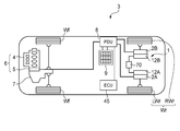
- a vehicle 3 shown in FIG. 1 is a hybrid vehicle having a drive device 6 (hereinafter referred to as a front wheel drive device) in which an internal combustion engine 4 and an electric motor 5 are connected in series at the front portion of the vehicle.
- the power of the driving device 1 (hereinafter referred to as a rear wheel driving device) provided at the rear of the vehicle separately from the front wheel driving device 6 is the rear wheel Wr ( RWr, LWr).
- the electric motor 5 of the front wheel drive device 6 and the electric motors 2A and 2B of the rear wheel drive device 1 on the rear wheel Wr side are connected to the battery 9 via the PDU 8 (power drive unit), and supply power from the battery 9 to the battery 9. Energy regeneration is performed through the PDU 8.
- the PDU 8 is connected to an ECU 45 described later.
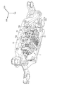
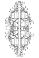
- FIG. 2 is a longitudinal sectional view of the entire rear wheel drive device 1.
- 10A and 10B are left and right axles on the rear wheel Wr side of the vehicle, and are coaxial in the vehicle width direction. Is arranged.
- the reduction gear case 11 of the rear wheel drive device 1 is formed in a substantially cylindrical shape as a whole, and includes an electric motor 2A and 2B for driving an axle, and a planetary gear type reduction gear for reducing the drive rotation of the electric motors 2A and 2B.
- the machines 12A and 12B are arranged coaxially with the axles 10A and 10B.
- the electric motor 2A and the planetary gear type reduction gear 12A control the left rear wheel LWr
- the electric motor 2B and the planetary gear type reduction gear 12B control the right rear wheel RWr
- the electric motor 2A, the planetary gear type reduction gear 12A, the electric motor 2B, planetary gear reducer 12B are disposed symmetrically in the vehicle width direction in the reducer case 11.
- the speed reducer case 11 is supported by the support portions 13 a and 13 b of the frame member 13 that is a part of the frame that is the skeleton of the vehicle 3 and the frame of the rear wheel drive device 1 (not shown).
- the support portions 13a and 13b are provided on the left and right with respect to the center of the frame member 13 in the vehicle width direction.
- the arrow in FIG. 4 has shown the positional relationship in the state in which the rear-wheel drive device 1 was mounted in the vehicle.
- the stators 14A and 14B of the electric motors 2A and 2B are respectively fixed inside the left and right ends of the speed reducer case 11, and annular rotors 15A and 15B are rotatably arranged on the inner peripheral sides of the stators 14A and 14B.
- Cylindrical shafts 16A and 16B surrounding the outer periphery of the axles 10A and 10B are coupled to the inner peripheral portions of the rotors 15A and 15B, and the cylindrical shafts 16A and 16B are decelerated so as to be coaxially rotatable with the axles 10A and 10B.
- the machine case 11 is supported by end walls 17A and 17B and intermediate walls 18A and 18B via bearings 19A and 19B.
- the rotational position information of the rotors 15A and 15B is transmitted to the end walls 17A and 17B of the reduction gear case 11 on the outer periphery on one end side of the cylindrical shafts 16A and 16B, and the control controllers (not shown) of the motors 2A and 2B.
- Resolvers 20A and 20B are provided for feedback.
- the planetary gear speed reducers 12A and 12B include sun gears 21A and 21B, a plurality of planetary gears 22A and 22B meshed with the sun gear 21, planetary carriers 23A and 23B that support the planetary gears 22A and 22B, and planetary gears. Ring gears 24A and 24B meshed with the outer peripheral sides of 22A and 22B, and the driving forces of the electric motors 2A and 2B are input from the sun gears 21A and 21B, and the reduced driving force is output through the planetary carriers 23A and 23B. It is like that.
- Sun gears 21A and 21B are formed integrally with cylindrical shafts 16A and 16B.
- the planetary gears 22A and 22B include large-diameter first pinions 26A and 26B that are directly meshed with the sun gears 21A and 21B, and a second pinion having a smaller diameter than the first pinions 26A and 26B.
- the first and second pinions 26A and 26B and the second pinions 27A and 27B are integrally formed in a state of being coaxially and offset in the axial direction.
- the planetary gears 22A and 22B are supported by the planetary carriers 23A and 23B, and the planetary carriers 23A and 23B are supported so as to be integrally rotatable with the axially inner ends extending inward in the radial direction and being spline-fitted to the axles 10A and 10B.
- the intermediate walls 18A and 18B are supported.
- the intermediate walls 18A and 18B separate the motor housing space for housing the motors 2A and 2B and the speed reducer space for housing the planetary gear type speed reducers 12A and 12B, and the axial distance from the outer diameter side to the inner diameter side. It is configured to bend so as to spread.
- Bearings 33A and 33B for supporting the planetary carriers 23A and 23B are arranged on the inner diameter side of the intermediate walls 18A and 18B and on the planetary gear type speed reducers 12A and 12B, and the outer diameter side of the intermediate walls 18A and 18B.
- bus rings 41A and 41B for the stators 14A and 14B are arranged on the side of the electric motors 2A and 2B (see FIG. 2).
- the ring gears 24A and 24B are disposed opposite to each other at gears 28A and 28B whose inner peripheral surfaces are meshed with the second pinions 27A and 27B having a small diameter, and smaller in diameter than the gear parts 28A and 28B, at an intermediate position of the speed reducer case 11.
- the maximum radii of the ring gears 24A and 24B are set to be smaller than the maximum distance from the center of the axles 10A and 10B of the first pinions 26A and 26B.
- the small diameter portions 29A and 29B are spline-fitted to an inner race 51 of a one-way clutch 50, which will be described later, and the ring gears 24A and 24B are configured to rotate integrally with the inner race 51 of the one-way clutch 50.
- a cylindrical space is secured between the speed reducer case 11 and the ring gears 24A and 24B, and hydraulic brakes 60A and 60B that constitute braking means for the ring gears 24A and 24B are provided in the space portions in the first pinion 26A, wrapped in 26B and radially, the second pinion 27A, is arranged to wrap at 27B in the axial direction.
- the hydraulic brakes 60A and 60B include a plurality of fixed plates 35A and 35B that are spline-fitted to the inner peripheral surface of a cylindrical outer diameter side support portion 34 that extends in the axial direction on the inner diameter side of the speed reducer case 11, a ring gear 24A, A plurality of rotating plates 36A, 36B that are spline-fitted on the outer peripheral surface of 24B are alternately arranged in the axial direction, and these plates 35A, 35B, 36A, 36B are fastened and released by the annular pistons 37A, 37B. It is like that.
- the pistons 37 ⁇ / b> A and 37 ⁇ / b> B are formed between the left and right dividing walls 39 extending from the intermediate position of the reduction gear case 11 to the inner diameter side, and the outer diameter side support portion 34 and the inner diameter side support portion 40 connected by the left and right division walls 39.
- the pistons 37A and 37B are moved forward by introducing high pressure oil into the cylinder chambers 38A and 38B, and the oil is discharged from the cylinder chambers 38A and 38B.
- the pistons 37A and 37B are moved backward.
- the hydraulic brakes 60A and 60B are connected to an electric oil pump 70 disposed between the support portions 13a and 13b of the frame member 13 described above, as shown in FIG.
- the pistons 37A and 37B have first piston walls 63A and 63B and second piston walls 64A and 64B in the axial direction, and the piston walls 63A, 63B, 64A and 64B are cylindrical. Are connected by inner peripheral walls 65A and 65B. Therefore, an annular space that opens radially outward is formed between the first piston walls 63A and 63B and the second piston walls 64A and 64B. This annular space is formed on the inner periphery of the outer wall of the cylinder chambers 38A and 38B. It is partitioned in the axial direction left and right by partition members 66A and 66B fixed to the surface.
- a space between the left and right dividing walls 39 of the speed reducer case 11 and the second piston walls 64A and 64B is a first working chamber S1 (see FIG. 5) into which high-pressure oil is directly introduced, and the partition members 66A and 66B and the first piston wall
- a space between 63A and 63B is a second working chamber S2 (see FIG. 5) that is electrically connected to the first working chamber S1 through a through hole formed in the inner peripheral walls 65A and 65B.
- the second piston walls 64A and 64B and the partition members 66A and 66B are electrically connected to the atmospheric pressure.
- oil is introduced into the first working chamber S1 and the second working chamber S2 from a hydraulic circuit 71, which will be described later, and acts on the first piston walls 63A and 63B and the second piston walls 64A and 64B.
- the fixed plates 35A and 35B and the rotating plates 36A and 36B can be pressed against each other by the pressure of. Therefore, since the large pressure receiving area can be gained by the first and second piston walls 63A, 63B, 64A, 64B on the left and right in the axial direction, the fixing plates 35A, 35B A large pressing force against the rotating plates 36A and 36B can be obtained.
- the fixed plates 35A and 35B are supported by the outer diameter side support portion 34 extending from the reduction gear case 11, while the rotation plates 36A and 36B are supported by the ring gears 24A and 24B.
- the frictional engagement between the plates 35A, 35B, 36A, and 36B causes a braking force to be applied to the ring gears 24A and 24B, thereby fixing them.
- piston 37A, the fastening by 37B is released, the ring gear 24A, free rotation of 24B is allowed.
- a space is secured between the coupling portions 30A and 30B of the ring gears 24A and 24B facing each other in the axial direction, and only power in one direction is transmitted to the ring gears 24A and 24B in the space to transmit power in the other direction.
- a one-way clutch 50 is arranged to be shut off.
- the one-way clutch 50 has a large number of sprags 53 interposed between an inner race 51 and an outer race 52.
- the inner race 51 is connected to the small diameter portions 29A, 29B of the ring gears 24A, 24B by spline fitting. It is configured to rotate integrally.
- the outer race 52 is positioned by the inner diameter side support portion 40 and is prevented from rotating.
- the one-way clutch 50 is configured to engage and lock the rotation of the ring gears 24A and 24B when the vehicle 3 moves forward with the power of the electric motors 2A and 2B. More specifically, the one-way clutch 50 is engaged when rotational power in the forward direction on the motors 2A, 2B side (rotation direction when the vehicle 3 is advanced) is input to the wheel Wr side. When the rotational power in the reverse direction on the electric motors 2A and 2B is input to the wheels Wr, the non-engagement state is established. When the rotational power in the forward direction on the wheels Wr is input to the electric motors 2A and 2B, The engaged state is established when the rotating power in the reverse direction on the wheel Wr side is input to the electric motors 2A, 2B while being engaged.
- the one-way clutch 50 and the hydraulic brakes 60A and 60B are provided in parallel on the power transmission path between the electric motors 2A and 2B and the wheels Wr.
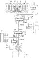
- the hydraulic circuit 71 supplies the oil sucked from the suction port 70a disposed in the oil pan 80 (first oil reservoir) and discharged from the electric oil pump 70 to the low pressure oil path switching valve 73 and the brake oil path switching valve 74.
- the first brake chamber S1 of the hydraulic brakes 60A and 60B is configured to be capable of being refueled via the low pressure oil passage switching valve 73, and the motors 2A and 2B and the planetary gear speed reducers 12A and 12B are lubricated and cooled. It is comprised so that supply to the part 91 is possible.
- the electric oil pump 70 can be operated (operated) in at least two modes of a high pressure mode and a low pressure mode by an electric motor 90 composed of a position sensorless brushless DC motor, and is controlled by PID control.
- Reference numeral 92 denotes a pressure sensor that detects the hydraulic pressure in the brake fluid passage 77.
- the hydraulic circuit 71 is also provided with a temperature sensor (not shown).
- the low-pressure oil passage switching valve 73 includes a first line oil passage 75a on the electric oil pump 70 side constituting the line oil passage 75 and a second line oil passage 75b on the brake oil passage switching valve 74 side constituting the line oil passage 75. And a first low-pressure oil passage 76 a communicating with the lubrication / cooling unit 91 and a second low-pressure oil passage 76 b communicating with the lubrication / cooling unit 91. Further, the low-pressure oil passage switching valve 73 allows the first line oil passage 75a and the second line oil passage 75b to always communicate with each other and the line oil passage 75 is selectively used as the first low-pressure oil passage 76a or the second low-pressure oil passage 76b.
- a valve body 73a that communicates with the valve body 73a, a spring 73b that urges the valve body 73a in a direction that communicates the line oil passage 75 and the first low-pressure oil passage 76a (rightward in FIG. 5), and a valve body 73a that communicates with the line oil passage.
- an oil chamber 73c that presses the line oil passage 75 and the second low-pressure oil passage 76b in a direction (leftward in FIG. 5) in communication with the oil pressure of 75. Therefore, the valve element 73a is urged by the spring 73b in a direction (rightward in FIG.
- the urging force of the spring 73b is, as shown in FIG. 6A, the valve body in the oil pressure of the line oil passage 75 that is input to the oil chamber 73c when the electric oil pump 70 is operated in the low pressure mode described later. 73a does not move, and the line oil passage 75 is cut off from the second low pressure oil passage 76b and communicated with the first low pressure oil passage 76a (hereinafter, the position of the valve body 73a in FIG. 6), when the electric oil pump 70 is operated in the high pressure mode, which will be described later, in the oil pressure of the line oil passage 75 that is input to the oil chamber 73c, as shown in FIG.
- the line oil passage 75 is set so as to be disconnected from the first low pressure oil passage 76a and communicated with the second low pressure oil passage 76b (hereinafter, the position of the valve body 73a in FIG. 6B is referred to as a high pressure side position). ).
- the brake oil passage switching valve 74 includes a second line oil passage 75 b constituting the line oil passage 75, a brake oil passage 77 connected to the hydraulic brakes 60 ⁇ / b> A and 60 ⁇ / b> B, and a reservoir 79 (first 2 oil reservoir). Further, the brake oil passage switching valve 74 connects and disconnects the second line oil passage 75b and the brake oil passage 77, and shuts off the valve body 74a from the second line oil passage 75b and the brake oil passage 77. Spring 74b urging in the direction (rightward in FIG. 5) and the direction in which the valve body 74a communicates with the second line oil passage 75b and the brake oil passage 77 by the oil pressure of the line oil passage 75 (leftward in FIG.
- valve body 74a is urged by the spring 74b in a direction (to the right in FIG. 5) that blocks the second line oil passage 75b and the brake oil passage 77, and is input to the oil chamber 74c.
- the hydraulic pressure of 75 enables the second line oil passage 75b and the brake oil passage 77 to be pressed in a direction (leftward in FIG. 5).
- the urging force of the spring 74b is the hydraulic pressure of the line oil passage 75 that is input to the oil chamber 74c while the electric oil pump 70 is operating in the low pressure mode and the high pressure mode. 7 (b), the brake oil passage 77 is cut off from the high-position drain 78 and communicated with the second line oil passage 75b. That is, regardless of whether the electric oil pump 70 is operated in the low pressure mode or the high pressure mode, the oil pressure of the line oil passage 75 input to the oil chamber 74c exceeds the urging force of the spring 74b, and the brake oil passage 77 is increased. Shut off from the position drain 78 and communicate with the second line oil passage 75b.
- the hydraulic brakes 60 ⁇ / b> A and 60 ⁇ / b> B are communicated with the storage portion 79 via the brake oil passage 77 and the high position drain 78.
- the reservoir 79 is higher in the vertical direction than the oil pan 80, more preferably, the vertical uppermost portion of the reservoir 79 is the uppermost vertical direction of the first working chamber S1 of the hydraulic brakes 60A and 60B. It arrange
- the brake oil passage switching valve 74 when the brake oil passage switching valve 74 is closed, the oil stored in the first working chamber S1 of the hydraulic brakes 60A and 60B is not directly discharged to the oil pan 80 but is discharged to the storage unit 79. Configured to be stored. The oil overflowing from the reservoir 79 is configured to be discharged to the oil pan 80.
- the storage portion side end portion 78 a of the high position drain 78 is connected to the bottom surface of the storage portion 79.
- the oil chamber 74 c of the brake oil passage switching valve 74 is connectable to a second line oil passage 75 b constituting the line oil passage 75 via a pilot oil passage 81 and a solenoid valve 83.
- the solenoid valve 83 is an electromagnetic three-way valve controlled by the ECU 45, and the second line oil passage 75 b is connected to the pilot oil passage 81 when the ECU 45 is not energized to the solenoid 174 (see FIG. 8). Then, the oil pressure of the line oil passage 75 is input to the oil chamber 74c.
- the solenoid valve 83 is provided on a three-way valve member 172 and a case member 173, and is energized by receiving a power supplied via a cable (not shown) and a solenoid 174.
- a solenoid valve body 175 that is pulled right by receiving an exciting force
- a solenoid spring 176 that is housed in a spring holding recess 173a formed at the center of the case member 173, and biases the solenoid valve body 175 leftward
- a guide member 177 which is provided in the direction valve member 172 and slidably guides the advancement / retraction of the solenoid valve body 175.
- the three-way valve member 172 is a substantially bottomed cylindrical member, and includes a right concave hole 181 formed from the right end portion to the substantially middle portion along the center line, and from the left end portion also along the center line.
- a left concave hole 182 formed to the vicinity of the right concave hole 181, and a first radial hole formed along the direction orthogonal to the center line between the right concave hole 181 and the left concave hole 182 183, a second radial hole 184 that communicates with a substantially middle portion of the right concave hole 181 and is formed along a direction orthogonal to the center line, and a left concave hole 182 that is formed along the center line.
- a first axial hole 185 that communicates with the one radial hole 183, and a second axial hole 186 that is formed along the center line and communicates with the first radial hole 183 and the right concave hole 181.
- a ball 187 that opens and closes the first axial hole 185 is placed in the bottom of the left concave hole 182 of the three-way valve member 172 so as to be movable in the left-right direction, and on the inlet side of the left concave hole 182
- a cap 188 for restricting the detachment of the ball 187 is fitted.
- the cap 188 has a through hole 188a that communicates with the first axial hole 185 along the center line.
- the second axial hole 186 is opened and closed by contact or non-contact of the root portion of the opening / closing projection 175a formed at the left end portion of the solenoid valve body 175 that moves left and right.
- the ball 187 that opens and closes the first axial hole 185 is moved to the left and right by the tip of the opening and closing protrusion 175a of the solenoid valve body 175 that moves left and right.
- the solenoid valve body 175 is moved to the left by receiving the urging force of the solenoid spring 176 as shown in FIG. 8A by deenergizing the solenoid 174 (no power supply).
- the tip of the opening / closing protrusion 175a of the solenoid valve body 175 pushes the ball 187, the first axial hole 185 is opened, and the root of the opening / closing protrusion 175a of the solenoid valve body 175 is the second axial hole 186.
- the second axial hole 186 is closed.
- the second line oil passage 75b constituting the line oil passage 75 communicates with the oil chamber 74c from the first axial hole 185 and the first radial hole 183 via the pilot oil passage 81 (hereinafter, FIG. 8).
- the position of the solenoid valve body 175 may be referred to as a valve opening position.
- the solenoid valve body 175 moves to the right against the urging force of the solenoid spring 176 by receiving the exciting force of the solenoid 174 as shown in FIG.
- the oil pressure from the through hole 188a pushes the ball 187
- the first axial hole 185 is closed, and the root portion of the opening / closing protrusion 175a of the solenoid valve body 175 is separated from the second axial hole 186, The second axial hole 186 is opened.
- the oil stored in the oil chamber 74c is discharged to the oil pan 80 through the first radial hole 183, the second axial hole 186, and the second radial hole 184, and the second line oil passage 75b.
- the pilot oil passage 81 are shut off (hereinafter, the position of the solenoid valve body 175 in FIG. 8B may be referred to as a valve closing position).
- the relief valve 84 is connected to discharge the oil in the low pressure common oil passage 76c to the oil pan 80 through the relief drain 86 and reduce the oil pressure. ing.
- orifices 85a and 85b as flow path resistance means are formed in the first low pressure oil passage 76a and the second low pressure oil passage 76b, respectively.
- orifice 85a is configured to be larger in diameter than the orifice 85b of the second low pressure oil passage 76 b.
- the flow resistance of the second low pressure oil passage 76b is larger than the flow resistance of the first low pressure oil passage 76a, and the amount of pressure reduction in the second low pressure oil passage 76b when the electric oil pump 70 is operating in the high pressure mode is
- the pressure reduction amount in the first low-pressure oil passage 76a during operation of the electric oil pump 70 in the low-pressure mode is greater, and the oil pressure in the low-pressure common oil passage 76c in the high-pressure mode and the low-pressure mode is substantially equal.
- the low-pressure oil passage switching valve 73 connected to the first low-pressure oil passage 76a and the second low-pressure oil passage 76b is more than the oil pressure in the oil chamber 73c when the electric oil pump 70 is operating in the low-pressure mode.
- the urging force of the spring 73b wins, and the urging force of the spring 73b causes the valve body 73a to be positioned at the low pressure side position, blocking the line oil passage 75 from the second low pressure oil passage 76b and communicating with the first low pressure oil passage 76a.
- the oil flowing through the first low-pressure oil passage 76a is subjected to flow resistance by the orifice 85a and is depressurized, and reaches the lubrication / cooling section 91 via the low-pressure common oil passage 76c.
- the electric oil pump 70 when the electric oil pump 70 is operating in the high pressure mode, the oil pressure in the oil chamber 73c is greater than the urging force of the spring 73b, and the valve element 73a is positioned at the high pressure side position against the urging force of the spring 73b.
- the line oil passage 75 is cut off from the first low-pressure oil passage 76a and communicated with the second low-pressure oil passage 76b.
- the oil flowing through the second low-pressure oil passage 76b is depressurized by the orifice 85b due to a larger passage resistance than the orifice 85a, and reaches the lubrication / cooling section 91 via the low-pressure common oil passage 76c.
- the oil passage having the small flow resistance is automatically switched from the oil passage having the small flow resistance to the oil passage having the large flow resistance in accordance with the change in the oil pressure of the line oil passage 75. It is suppressed that excessive oil is supplied to the lubrication / cooling unit 91 in the mode.
- a plurality of orifices 85c as other flow path resistance means are provided in the oil path from the low pressure common oil path 76c to the lubrication / cooling section 91.
- the plurality of orifices 85c are set so that the minimum flow passage cross-sectional area of the orifice 85a of the first low-pressure oil passage 76a is smaller than the minimum flow passage cross-sectional area of the plurality of orifices 85c. That is, the flow resistance of the orifice 85a of the first low-pressure oil passage 76a is set larger than the flow resistance of the plurality of orifices 85c.
- the minimum flow path cross-sectional area of the plurality of orifices 85c is the sum of the minimum flow path cross-sectional area of each orifice 85c.
- the ECU 45 (see FIG. 1) is a control device for performing various controls of the entire vehicle.
- the ECU 45 is input with vehicle speed, steering angle, accelerator pedal opening AP, shift position, SOC, and the like. From the ECU 45, a signal for controlling the internal combustion engine 4, a signal for controlling the electric motors 2A and 2B, a signal indicating a power generation state / charge state / discharge state in the battery 9, a control signal for the solenoid 174 of the solenoid valve 83, electric oil A control signal for controlling the pump 70 is output.
- the ECU 45 has at least a function as an electric motor control device for controlling the electric motors 2A and 2B and a function as a connection / disconnection means control device for controlling the hydraulic brakes 60A and 60B as connection / disconnection means.
- the ECU 45 as the connection / disconnection means control device controls the electric oil pump 70 and the solenoid 174 of the solenoid valve 83 based on the driving state of the electric motors 2A, 2B and / or the driving command (driving signal) of the electric motors 2A, 2B.
- the electric oil pump 70 may be controlled by rotational speed control or torque control, and is based on the target hydraulic pressure in the first working chamber S1 and the second working chamber S2.
- the determination is made based on the actual hydraulic pressure and the target hydraulic pressure in the first working chamber S1 and the second working chamber S2 detected from the pressure sensor 92.
- the actual hydraulic pressure from the pressure sensor 92 it may be using the estimated hydraulic pressure obtained by the hydraulic estimating means.
- FIG. 5 shows the hydraulic circuit 71 in a state where the hydraulic brakes 60A and 60B are released while the vehicle is stopped.
- the ECU 45 does not operate the electric oil pump 70.
- the valve body 73a of the low pressure oil passage switching valve 73 is located at the low pressure side position
- the valve body 74a of the brake oil passage switching valve 74 is located at the valve closing position, and no hydraulic pressure is supplied to the hydraulic circuit 71. .
- FIG. 9 shows a state in which the hydraulic brakes 60A and 60B are released while the vehicle is running.
- the ECU 45 operates the electric oil pump 70 in the low pressure mode. Further, the ECU 45 energizes the solenoid 174 of the solenoid valve 83, and the second line oil passage 75b and the pilot oil passage 81 are shut off.
- the valve body 74a of the brake oil passage switching valve 74 is positioned at the valve closing position by the urging force of the spring 74b, and the second line oil passage 75b and the brake oil passage 77 are shut off, and the brake oil passage 77 and The high position drain 78 is communicated, and the hydraulic brakes 60A and 60B are released.
- the brake oil passage 77 is connected to the storage portion 79 via a high position drain 78.
- the low pressure oil passage switching valve 73 has a biasing force of the spring 73b larger than the oil pressure of the line oil passage 75 operating in the low pressure mode of the electric oil pump 70 inputted to the oil chamber 73c at the right end in the figure.
- the body 73a is located at the low-pressure side position, and the line oil passage 75 is cut off from the second low-pressure oil passage 76b and communicated with the first low-pressure oil passage 76a.
- the oil in the line oil passage 75 is depressurized by the orifice 85 a through the first low-pressure oil passage 76 a and supplied to the lubrication / cooling unit 91.
- FIG. 10 shows the hydraulic circuit 71 in a state where the hydraulic brakes 60A and 60B are weakly engaged.
- the weak engagement means a state in which power can be transmitted but is fastened with a weak fastening force with respect to the fastening force of the hydraulic brakes 60A and 60B.
- the ECU 45 operates the electric oil pump 70 in the low pressure mode. Further, the ECU 45 deenergizes the solenoid 174 of the solenoid valve 83 and inputs the hydraulic pressure of the second line oil passage 75 b to the oil chamber 74 c of the brake oil passage switching valve 74.
- the hydraulic pressure in the oil chamber 74c is superior to the urging force of the spring 74b, the valve body 74a is positioned at the valve open position, the brake oil passage 77 and the high position drain 78 are shut off, and the second line oil passage. 75b and the brake oil passage 77 are communicated, and the hydraulic brakes 60A and 60B are weakly engaged.
- the low-pressure oil passage switching valve 73 is operated in the low-pressure mode of the electric oil pump 70 in which the urging force of the spring 73b is input to the oil chamber 73c at the right end in the figure, similarly to the release of the hydraulic brakes 60A and 60B. Since it is larger than the hydraulic pressure of the inner line oil passage 75, the valve body 73a is positioned at the low pressure side position, and the line oil passage 75 is cut off from the second low pressure oil passage 76b and communicated with the first low pressure oil passage 76a. As a result, the oil in the line oil passage 75 is depressurized by the orifice 85 a through the first low-pressure oil passage 76 a and supplied to the lubrication / cooling unit 91.
- FIG. 11 shows the hydraulic circuit 71 in a state where the hydraulic brakes 60A and 60B are engaged.
- the ECU 45 operates the electric oil pump 70 in the high pressure mode.
- the ECU 45 deenergizes the solenoid 174 of the solenoid valve 83 and inputs the hydraulic pressure of the second line oil passage 75 b to the oil chamber 74 c at the right end of the brake oil passage switching valve 74.
- the hydraulic pressure in the oil chamber 74c is superior to the urging force of the spring 74b
- the valve body 74a is positioned at the valve open position
- the brake oil passage 77 and the high position drain 78 are shut off, and the second line oil passage.
- 75b and the brake oil passage 77 are communicated, and the hydraulic brakes 60A and 60B are fastened.
- the low pressure oil passage switching valve 73 Located at the high pressure side position, the line oil passage 75 is blocked from the first low pressure oil passage 76a and communicated with the second low pressure oil passage 76b. As a result, the oil in the line oil passage 75 is depressurized by the orifice 85 b through the second low-pressure oil passage 76 b and supplied to the lubrication / cooling unit 91.
- the ECU 45 controls the operation mode (operating state) of the electric oil pump 70 and the opening and closing of the solenoid valve 83 to release or fasten the hydraulic brakes 60A and 60B, and the motors 2A and 2B and the wheels Wr. with switching between side isolated state and connected state, it is possible to control the engagement force of the hydraulic brake 60A, 60B.
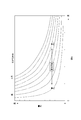
- FIG. 12 is a graph showing load characteristics of the electric oil pump 70.
- the low pressure mode (hydraulic pressure PL) reduces the power of the electric oil pump 70 to about 1/4 to 1/5 while maintaining the oil supply flow rate. Can be reduced. That is, the load of the electric oil pump 70 is small in the low pressure mode, and the power consumption of the electric motor 90 that drives the electric oil pump 70 can be reduced compared to the high pressure mode.
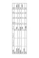
- FIG. 13 shows the relationship between the front wheel drive device 6 and the rear wheel drive device 1 in each vehicle state, including the operating states of the electric motors 2A and 2B and the state of the hydraulic circuit 71.
- the front unit is a front wheel drive device 6, the rear unit is a rear wheel drive device 1, the rear motor is an electric motor 2A, 2B, EOP is an electric oil pump 70, SOL is a solenoid 174, OWC is a one-way clutch 50, and BRK is a hydraulic brake.
- 60A and 60B are represented.
- the rear wheel drive device 1 performs the rear wheel drive at a low vehicle speed with good motor efficiency such as EV start and EV cruise.
- a low vehicle speed with good motor efficiency such as EV start and EV cruise.
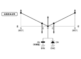
- the electric motors 2A and 2B are driven to rotate in the forward direction, forward torque is applied to the sun gears 21A and 21B.
- the one-way clutch 50 is engaged and the ring gears 24A and 24B are locked.
- the planetary carriers 23A and 23B rotate in the forward direction and travel forward.
- the planetary carrier 23A, the 23B running resistance from the axle 10A, 10B is acting in the opposite direction.
- the ignition is turned on and the torque of the electric motors 2A and 2B is increased, whereby the one-way clutch 50 is mechanically engaged and the ring gears 24A and 24B are locked.
- the electric oil pump 70 operates in the low pressure mode (Lo)
- the solenoid 174 of the solenoid valve 83 is not energized (OFF)
- the hydraulic brakes 60A, 60B Is in a weak fastening state.
- the one-way clutch 50 is engaged and power can be transmitted only by the one-way clutch 50.
- the hydraulic brakes 60A and 60B provided in parallel with the motors are also weakly engaged, and the electric motors 2A and 2B and the wheels Wr are connected to each other, so that forward rotational power input from the electric motors 2A and 2B is temporarily received.
- the fastening force of the hydraulic brakes 60 ⁇ / b> A and 60 ⁇ / b> B at this time is a weak fastening force as compared with deceleration regeneration and reverse travel described later.
- the hydraulic brake 60A By making the fastening force of the hydraulic brakes 60A, 60B when the one-way clutch 50 is engaged smaller than the fastening force of the hydraulic brakes 60A, 60B when the one-way clutch 50 is not engaged, the hydraulic brake 60A , Power consumption for fastening 60B is reduced. Further, in this state, as described above, the oil in the line oil passage 75 is depressurized by the orifice 85a through the first low-pressure oil passage 76a and supplied to the lubrication / cooling section 91, and the lubrication / cooling section 91 is lubricated and cooled. Has been made.
- the rear wheel driving by the rear wheel driving device 1 changes to the front wheel driving by the front wheel driving device 6.
- the forward torque to travel forward from the axles 10A and 10B acts on the planetary carriers 23A and 23B.
- the clutch 50 is disengaged.
- the electric oil pump 70 operates in the low pressure mode (Lo)
- the solenoid 174 of the solenoid valve 83 is not energized (OFF)
- the hydraulic brakes 60A, 60B Is in a weak fastening state.
- the one-way clutch 50 is disengaged and power transmission is impossible only with the one-way clutch 50.
- the hydraulic brakes 60A and 60B provided in parallel with the clutch 50 are weakly engaged, and the motors 2A and 2B and the wheels Wr can be connected to each other so that the power can be transmitted. Rotational speed control is not required when shifting to the hour.
- the fastening force of the hydraulic brakes 60A and 60B at this time is also a weak fastening force as compared with deceleration regeneration or reverse travel described later.
- the oil in the line oil passage 75 is depressurized by the orifice 85a through the first low-pressure oil passage 76a and supplied to the lubrication / cooling section 91, and the lubrication / cooling section 91 is lubricated and cooled. Has been made.
- the electric oil pump 70 operates in the high pressure mode (Hi)
- the solenoid 174 of the solenoid valve 83 is deenergized (OFF)
- the hydraulic brakes 60A and 60B are turned on. It is in a fastening state (ON).
- the ring gears 24A and 24B are fixed, and the regenerative braking torque in the reverse direction acts on the motors 2A and 2B, and the motors 2A and 2B perform deceleration regeneration.
- the one-way clutch 50 is disengaged and power transmission is impossible only with the one-way clutch 50.
- the hydraulic brakes 60A and 60B provided in parallel with the clutch 50 are fastened, and the motors 2A and 2B and the wheels Wr can be connected to each other so that the power can be transmitted.
- the motor 2A By controlling 2B to the regenerative drive state, the energy of the vehicle can be regenerated.
- the oil in the line oil passage 75 is depressurized by the orifice 85b through the second low-pressure oil passage 76b and supplied to the lubrication / cooling section 91, and the lubrication / cooling section 91 is lubricated and cooled. Has been made.
- the front wheel drive device 6 and the rear wheel drive device 1 are driven by four wheels.
- the rear wheel drive device 1 is in the same state as the forward low vehicle speed shown in FIG. 15, and the hydraulic circuit 71 is also shown in FIG. It will be in the state shown.
- the front wheel drive device 6 drives the front wheels.
- the front wheel drive device 6 drives the front wheels.
- the forward torque to travel forward from the axles 10A and 10B acts on the planetary carriers 23A and 23B.
- the clutch 50 is disengaged.
- the electric oil pump 70 is operated in the low pressure mode (Lo)
- the solenoid 174 of the solenoid valve 83 is energized (ON)
- the hydraulic brakes 60A and 60B are released ( OFF). Accordingly, the accompanying rotation of the electric motors 2A and 2B is prevented, and the electric motors 2A and 2B are prevented from over-rotating at the high vehicle speed by the front wheel drive device 6.
- the oil in the line oil passage 75 is depressurized by the orifice 85a through the first low-pressure oil passage 76a and supplied to the lubrication / cooling section 91, and the lubrication / cooling section 91 is lubricated and cooled. Has been made.
- the electric oil pump 70 operates in the high pressure mode (Hi)
- the solenoid 174 of the solenoid valve 83 is deenergized (OFF)
- the hydraulic brakes 60A and 60B are turned on. It will be in a fastening state. Accordingly, the ring gears 24A and 24B are fixed, and the planetary carriers 23A and 23B rotate in the reverse direction to travel backward. Incidentally, the planetary carrier 23A, the 23B running resistance from the axle 10A, 10B is acting in the forward direction.
- the one-way clutch 50 is disengaged and power transmission is impossible only by the one-way clutch 50.
- the hydraulic brakes 60A and 60B provided in parallel with the clutch 50 are fastened, and the electric motors 2A and 2B and the wheels Wr can be connected to each other so that power can be transmitted, and the rotational power of the electric motors 2A and 2B can be maintained. Can reverse the vehicle.
- the oil in the line oil passage 75 is depressurized by the orifice 85b through the second low-pressure oil passage 76b and supplied to the lubrication / cooling section 91, and the lubrication / cooling section 91 is lubricated and cooled. Has been made.
- the rear wheel drive device 1 receives power from the running state of the vehicle, in other words, whether the rotation direction of the motors 2A, 2B is the forward direction or the reverse direction, and from either the motor side 2A, 2B or the wheel Wr side. Accordingly, the engagement / release of the hydraulic brakes 60A, 60B is controlled, and the engagement force is adjusted even when the hydraulic brakes 60A, 60B are engaged.
- FIG. 20 shows an electric oil pump 70 (EOP) when the vehicle is stopped, EV start ⁇ EV acceleration ⁇ engine acceleration ⁇ deceleration regeneration ⁇ medium speed cruise ⁇ acceleration ⁇ high speed cruise ⁇ deceleration regeneration ⁇ stop ⁇ reverse ⁇ stop. ) And one-way clutch 50 (OWC) and hydraulic brakes 60A and 60B (BRK).
- EOP electric oil pump 70
- the electric oil pump 70 is not operated (OFF), the one-way clutch 50 is not engaged (OFF), and the hydraulic pressure is The brakes 60A and 60B maintain a released (OFF) state.
- the accelerator pedal is stepped on, EV start and EV acceleration are performed by the rear wheel drive device 1 by rear wheel drive (RWD).
- the electric oil pump 70 is operated (Lo) in the low pressure mode, the one-way clutch 50 is engaged (ON), and the hydraulic brakes 60A and 60B are in a weakly engaged state.
- ENG traveling is performed by the internal combustion engine 4.
- the one-way clutch 50 is disengaged (OFF), and the electric oil pump 70 and the hydraulic brakes 60A and 60B are maintained as they are.
- deceleration regeneration such as when the brake is stepped on, the electric oil pump 70 operates in the high pressure mode (Hi) while the one-way clutch 50 remains disengaged (OFF), and the hydraulic brakes 60A and 60B are engaged (ON). .
- Hi high pressure mode
- the one-way clutch 50 remains disengaged (OFF)
- the hydraulic brakes 60A and 60B are engaged (ON).
- the state is the same as the above-described ENG traveling.
- the one-way clutch 50 is engaged (ON) again.
- the vehicle speed reaches from the middle vehicle speed range to the high vehicle speed range
- the ENG traveling (FWD) by the internal combustion engine 4 is performed again.
- the one-way clutch 50 is disengaged (OFF), and the hydraulic brakes 60A and 60B are released (OFF) while the electric oil pump 70 is operating (Lo) in the low pressure mode.
- the electric oil pump 70 is not operated (OFF), the one-way clutch 50 is disengaged (OFF), and the hydraulic brakes 60A and 60B are released (OFF).
- the one-way clutch 50 remains disengaged (OFF), the electric oil pump 70 operates (Hi) in the high pressure mode, and the hydraulic brakes 60A and 60B are engaged (ON).
- the electric oil pump 70 is not operated again (OFF), the one-way clutch 50 is disengaged (OFF), and the hydraulic brakes 60A and 60B are released (OFF).
- the hydraulic brakes 60A and 60B are maintained in the weakly engaged state at the time of the forward low vehicle speed and the forward vehicle speed, so that the electric motors 2A and 2B can be used even when the drive torque is temporarily reduced in the electric motors 2A and 2B. It becomes possible to prevent the transmission of power between the side and the wheel Wr side. Further, by setting the hydraulic brakes 60A and 60B to a weakly engaged state and keeping the wheel Wr side and the electric motors 2A and 2B sides capable of transmitting power, the rotational speed control is performed when the electric motors 2A and 2B are shifted to the regenerative drive state. Is no longer necessary.
- the hydraulic brakes 60A and 60B are released to prevent over-rotation of the electric motors 2A and 2B. Since the oil temperature of the hydraulic circuit 71 is sufficiently high at the forward high vehicle speed, the hydraulic brakes 60A and 60B can be fastened even after the shift to deceleration regeneration.
- the oil temperature sensor 71 detects the oil temperature of the hydraulic circuit 71 (step S1), and then the pressure sensor 92 detects the oil pressure (Ps) of the hydraulic circuit 71 (step S2).
- the actual rotational speed (Nact) of the electric oil pump 70 is detected (step S3), and the mode is determined (step S4).
- the mode to be selected corresponds to the vehicle state shown in FIG.
- the stop mode in which the hydraulic brakes 60A and 60B are released in response to the stop state, the forward low vehicle speed, the forward vehicle speed, and the acceleration state Corresponding to the low vehicle speed / acceleration mode in which the hydraulic brakes 60A, 60B are weakly engaged, high vehicle speed mode in which the hydraulic brakes 60A, 60B are released in response to the high vehicle speed state, and hydraulic pressure in response to the deceleration regeneration state It is classified into a regenerative mode in which the brakes 60A and 60B are engaged, and a reverse mode in which the hydraulic brakes 60A and 60B are engaged in response to the reverse state.
- step S5 it is determined whether or not the vehicle is in the stop mode.
- the rotational speed command value (Ncmd) of the electric oil pump 70 is set to zero in order to stop the electric oil pump 70 (step S6).
- the number of rotations of the electric oil pump 70 necessary for supplying a predetermined amount of oil to the lubrication / cooling unit 91 according to the oil temperature ( Nlc) is calculated (step S7).
- step S8 it is determined whether or not the high vehicle speed mode is set.
- the electric motor necessary for supplying a predetermined amount of oil to the lubrication / cooling unit 91 is supplied with the rotational speed command value (Ncmd) of the electric oil pump 70 in order to release the hydraulic brakes 60A and 60B.
- the rotational speed (Nlc) of the oil pump 70 is set (step S9).
- the target hydraulic pressure becomes zero from the low pressure hydraulic pressure (PL)
- the PID correction value becomes negative, and a predetermined amount of oil is supplied to the lubrication / cooling unit 91. It is avoided that the rotational speed (Nlc) of the electric oil pump 70 necessary for supplying the electric oil pump falls below.
- step S10 the target hydraulic pressure (Pt) is calculated (step S10). That is, a predetermined low pressure hydraulic pressure (hydraulic pressure PL in the low pressure mode) in which the hydraulic brakes 60A and 60B are in a weak engagement state is calculated in the low vehicle speed / acceleration mode, and the hydraulic brakes 60A and 60B in the regenerative mode or reverse mode. A predetermined high pressure hydraulic pressure (hydraulic pressure PH in the high pressure mode) that is in the engaged state is calculated.
- a differential pressure ( ⁇ P) obtained by subtracting the hydraulic pressure (Ps) of the hydraulic circuit 71 detected by the pressure sensor 92 from the calculated target hydraulic pressure (Pt) is calculated (step S11), and PID correction of the differential pressure ( ⁇ P) is performed.
- a PID correction value (Pc), which is a value, is calculated (step S12).
- the rotational speed (Nc1) of the electric oil pump 70 corresponding to the PID correction value (Pc) is calculated based on the conversion relationship obtained in advance (step S13), and a predetermined amount of oil is supplied to the lubrication / cooling unit 91.
- the value obtained by adding the number of rotations (Nc1) of the electric oil pump 70 corresponding to the PID correction value (Pc) to the number of rotations (Nlc) of the electric oil pump 70 necessary for the operation is a command value for the number of rotations of the electric oil pump 70 (Ncmd) is set (step S14).
- a command value for the number of rotations of the electric oil pump 70 (Ncmd) is set (step S14).
- the ECU 45 connects the electric motors 2A, 2B and the wheels Wr when the forward rotational power of the electric motors 2A, 2B is input to the wheels Wr.
- the hydraulic brakes 60A and 60B are fastened so as to be in a state.
- the one-way clutch 50 is engaged when the forward rotational power on the motors 2A, 2B side is input to the wheel Wr side, and the power transmission is performed only by the one-way clutch 50.
- the hydraulic brakes 60A and 60B are also fastened in parallel, and the electric motors 2A and 2B and the wheels Wr are connected to each other so that the forward rotational power input from the electric motors 2A and 2B is temporarily received.
- the one-way clutch 50 can be prevented from being disengaged and becoming unable to transmit power, such as when the speed is lowered.
- the one-way clutch 50 is provided in parallel with the hydraulic brakes 60A and 60B, the one-way clutch 50 is engaged when the forward rotational power on the motors 2A and 2B side is input to the wheels Wr. As a result, a delay in response can be prevented, and the fastening force of the hydraulic brakes 60A and 60B can be reduced and the fastening time can be shortened.
- the ECU 45 causes the electric motors 2A, 2B and the wheel Wr to be connected when the forward rotational power on the wheel Wr side is input to the electric motors 2A, 2B.
- the hydraulic brakes 60A and 60B are fastened, and the electric motors 2A and 2B are controlled to be in a regenerative drive state or controlled to be in a non-drive state.
- the one-way clutch 50 is disengaged and power transmission is impossible only with the one-way clutch 50.
- the hydraulic brakes 60A and 60B provided in parallel are fastened and the electric motors 2A and 2B and the wheels Wr are connected to each other, so that the power can be transmitted.
- the electric motors 2A and 2B By controlling the electric motors 2A and 2B in the regenerative drive state in this state, the energy of the vehicle 3 can be regenerated.
- the hydraulic brakes 60A and 60B are fastened so that when the electric motors 2A and 2B are shifted to the regenerative driving state, The rotational speed control for connecting the wheel Wr side is not necessary, and the responsiveness of the rear wheel drive device 1 is improved.
- the ECU 45 can control the fastening force of the hydraulic brakes 60A, 60B in the engaged state, and the forward rotational power on the wheel Wr side is input to the electric motors 2A, 2B side.
- the fastening force of the hydraulic brakes 60A and 60B when the electric motors 2A and 2B are in the non-driven state is controlled to be weaker than the fastening force of the hydraulic brakes 60A and 60B when the electric motors 2A and 2B are in the regenerative drive state.
- the ECU 45 uses the fastening force of the hydraulic brakes 60A and 60B when the forward rotational power on the electric motors 2A and 2B side is input to the wheel Wr side in the forward direction on the wheel Wr side.
- Rotational power is input to the electric motors 2A and 2B, and control is performed so as to be weaker than the fastening force of the hydraulic brakes 60A and 60B when controlling the electric motors 2A and 2B to the regenerative drive state. Since the one-way clutch 50 and the hydraulic brakes 60A, 60B are provided in parallel, when the forward rotational power on the motors 2A, 2B side is input to the wheel Wr side, that is, the one-way clutch 50 is engaged.
- the ECU 45 causes the electric motors 2A, 2B and the wheels Wr to be connected when the rotational power in the reverse direction of the electric motors 2A, 2B is input to the wheels Wr.
- the hydraulic brakes 60A and 60B are fastened.
- the one-way clutch 50 is disengaged and power transmission is impossible only with the one-way clutch 50.
- the hydraulic brakes 60A and 60B provided in parallel are fastened and the electric motors 2A and 2B and the wheels Wr are connected to each other, so that the power can be transmitted and the vehicle can be moved backward.
- the ECU 45 applies the fastening force of the hydraulic brakes 60A, 60B when the forward rotational power on the motors 2A, 2B side is input to the wheels Wr side to the reverse of the motors 2A, 2B side.
- Control is performed so as to be weaker than the fastening force of the hydraulic brakes 60A and 60B when the rotational power in the direction is input to the wheel Wr side. Since the one-way clutch 50 and the hydraulic brakes 60A, 60B are provided in parallel, when the forward rotational power on the motors 2A, 2B side is input to the wheel Wr side, that is, the one-way clutch 50 is engaged.
- 60B can be made weaker than the fastening force, and energy consumption for fastening the hydraulic brakes 60A, 60B can be reduced.
- the hydraulic brakes 60A and 60B having oil chambers for storing the oil supplied by the electric oil pump 70 are employed as the connecting and disconnecting means, so that the shape and structure of the oil passages and oil chambers are adopted. Accordingly, the fastening force and the area to which the fastening force is applied can be adjusted. Further, by controlling the electric oil pump 70 based on the driving state of the electric motors 2A and 2B and / or the driving command of the electric motors 2A and 2B, it is possible to suppress an excessive or excessive operation of the electric oil pump 70.
- connection / disconnection means is not limited to a hydraulic type, and mechanical connection / disconnection means may be used.
- the one-way clutch 50 and the hydraulic brakes 60A and 60B are provided in parallel, when the electric motors 2A and 2B are driven by powering, that is, the one-way clutch 50 is in the engaged state.
- the fastening force of the hydraulic brakes 60A and 60B at the time is set to be weaker than the fastening force of the hydraulic brakes 60A and 60B when the electric motor is regeneratively driven or reversely driven, that is, when the one-way clutch 50 is not engaged. Accordingly, the operating state of the electric oil pump 70 when the electric motors 2A and 2B are driven by power is lower than the operating state of the electric oil pump 70 when the electric motors 2A and 2B are driven regeneratively.
- the operating state of the electric oil pump 70 when the electric motors 2A and 2B are driven by power running is the electric state when the electric motors 2A and 2B are driven by reverse power running.
- power consumption can be reduced.
- the hydraulic brake when the forward rotational power on the wheel Wr side is input to the electric motors 2A and 2B, the hydraulic brake is set so that the electric motors 2A and 2B and the wheel Wr side are connected.
- the vehicle speed exceeds a predetermined value with the hydraulic brakes 60A and 60B engaged, with the hydraulic brakes 60A and 60B engaged, the engaged hydraulic brakes 60A and 60B are released to prevent over-rotation of the electric motors 2A and 2B. can do.
- the drive device of the second embodiment has the same configuration except for the arrangement of the rear wheel drive device 1, the hydraulic brake, and the one-way clutch of the first embodiment.
- the same reference numerals are given and the description thereof is omitted.
- a cylindrical space is secured between the speed reducer case 11 and the ring gear 24A, and the hydraulic brake 60 is radially wrapped with the first pinion 26A in the space,
- the second pinion 27A is disposed so as to wrap in the axial direction.
- a plurality of fixed plates 35 that are spline-fitted to the inner peripheral surface of the speed reducer case 11 and a plurality of rotary plates 36 that are spline-fitted to the outer peripheral surface of the ring gear 24A are alternately arranged in the axial direction. These plates 35 and 36 are configured to be fastened and released by an annular piston 37.
- the piston 37 is accommodated in an annular cylinder chamber 38 formed between the speed reducer case 11, the support wall 45, and the cylindrical support portion 42.
- the piston 37 is inserted into the cylinder chamber 38 by introduction of high-pressure oil.
- the piston 37 is moved backward by discharging the oil from the cylinder chamber 38.
- the piston 37 has a first piston wall 63 and a second piston wall 64 in the axial direction, and the piston walls 63 and 64 are connected by a cylindrical inner peripheral wall 65. Therefore, an annular space that opens radially outward is formed between the first piston wall 63 and the second piston wall 64, and this annular space is a partition fixed to the inner peripheral surface of the outer wall of the cylinder chamber 38.
- the member 66 is partitioned forward and backward in the axial direction.
- a space between the left and right dividing walls 39 of the reduction gear case 11 and the second piston wall 64 is a first working chamber S1 into which high-pressure oil is directly introduced, and between the partition member 66 and the first piston wall 63 is an inner peripheral wall 65.
- the second working chamber S2 is electrically connected to the first working chamber S1 through the formed through hole.
- the second piston wall 64 and the partition member 66 are electrically connected to the atmospheric pressure.
- a cylindrical space is also secured between the reduction gear case 11 and the ring gear 24B, and only one direction of power is transmitted to the ring gears 24A and 24B and the power in the other direction is cut off in the space.
- a clutch 50 is arranged.
- the one-way clutch 50 has a large number of sprags 53 interposed between an inner race 51 and an outer race 52, and the inner race 51 is configured integrally with the gear portion 28B of the ring gear 24B.
- the outer race 52 while being positioned by the inner peripheral surface of the reducer case 11, is prevented from rotating.
- the one-way clutch 50 is configured to engage and lock the rotation of the ring gears 24A and 24B when the vehicle moves forward.
- the one-way clutch 50 is engaged when the rotational power in the forward direction of the electric motors 2A and 2B (the rotational direction when moving the vehicle 3 forward) is input to the wheels Wr.
- 2A, 2B side reverse rotational power is disengaged when input to the wheel Wr side
- wheel Wr side forward rotational power is disengaged when input to the motor 2A, 2B side.
- the planetary gear speed reducers 12A and 12B face each other in the axial direction at the center, and the ring gear 24A of the planetary gear speed reducer 12A and the ring gear 24B of the planetary gear speed reducer 12B are connected.
- the coupled ring gears 24 ⁇ / b> A and 24 ⁇ / b> B are rotatably supported by a cylindrical support portion 42 of the speed reducer case 11 via a bearing 43.
- one hydraulic brake 60 is provided in the space between the outer diameter side of the planetary gear speed reducer 12A and the speed reducer case 11, and the space between the outer diameter side of the planetary gear speed reducer 12B and the speed reducer case 11 is provided.
- One one-way clutch 50 is provided in the space, and a piston 37 that operates the hydraulic brake 60 is disposed on the outer diameter side of the bearing 43 between the hydraulic brake 60 and the one-way clutch 50.
- the same functions and functions as those of the rear wheel drive device 1 of the first embodiment are achieved.
- the drive unit can be reduced in size and weight, and the number of parts can be reduced.
- the rear wheel drive device 1 of the present embodiment is configured such that the planetary gear type speed reducers 12A and 12B are provided in the two electric motors 2A and 2B, respectively, and the left rear wheel LWr and the right rear wheel RWr are respectively controlled.
- the present invention is not limited to this, and one electric motor 2C and one speed reducer 12C may be connected to a differential device (not shown) as shown in FIG.
- the rear wheel drive device 1 of the present embodiment is illustrated as having the planetary gear type speed reducers 12A, 12B on the transmission path between the electric motors 2A, 2B and the rear wheels Wr (RWr, LWr). It is not necessary to provide a transmission such as the planetary gear speed reducers 12A and 12B. Further, the output shafts of the electric motors 2A and 2B and the axles 10A and 10B do not need to be arranged coaxially. Further, the front wheel drive device 6 may use the electric motor 5 as a sole drive source without using the internal combustion engine 4.
- Rear wheel drive system (vehicle drive system) 2A, 2B, 2C Electric motor 10A, 10B Axle 12A, 12B Planetary gear reducer (transmission) 21A, 21B Sun gear (second rotating element) 23A, 23B Planetary carrier (carrier, third rotating element) 24A, 24B Ring gear (first rotating element) 45 ECU (motor control device, connection / disconnection means control device) 50
- Electric oil pump (hydraulic supply source)
- Hydraulic control device 92
- Pressure sensor (hydraulic pressure detecting means) LWr Left rear wheel (wheel) RWr Right rear wheel (wheel) Wr Rear wheel (wheel) S1 First working chamber (oil chamber) S2 Second working chamber (oil chamber)
Abstract
Description
車両の駆動力を発生する電動機(例えば、後述の実施形態の電動機2A、2B、2C)と、
前記電動機を制御する電動機制御装置(例えば、後述の実施形態のECU45)と、
前記電動機と車輪(例えば、後述の実施形態の後輪Wr、LWr、RWr)との動力伝達経路上に設けられ、解放又は締結することにより電動機側と車輪側とを遮断状態又は接続状態にする断接手段(例えば、後述の実施形態の油圧ブレーキ60A、60B、60)と、
前記断接手段を制御する断接手段制御装置(例えば、後述の実施形態のECU45)と、を備えた車両用駆動装置(例えば、後述の実施形態の後輪駆動装置1)であって、
前記電動機と前記車輪との動力伝達経路上に前記断接手段と並列に設けられ、電動機側の順方向の回転動力が車輪側に入力されるときに係合状態となるとともに電動機側の逆方向の回転動力が車輪側に入力されるときに非係合状態となり、車輪側の順方向の回転動力が電動機側に入力されるときに非係合状態となるとともに車輪側の逆方向の回転動力が電動機側に入力されるときに係合状態となる一方向動力伝達手段(例えば、後述の実施形態の一方向クラッチ50)をさらに備え、
前記断接手段制御装置は、電動機側の順方向の回転動力が車輪側に入力されるときに、電動機側と車輪側とが接続状態となるように前記断接手段を締結することを特徴とする車両用駆動装置。
前記断接手段制御装置は、車輪側の順方向の回転動力が電動機側に入力されるときに、電動機側と車輪側とが接続状態となるように前記断接手段を締結することを特徴とする
前記電動機制御装置は、車輪側の順方向の回転動力が電動機側に入力されるときに、前記電動機を回生駆動状態に制御することを特徴とする。
前記断接手段制御装置は、前記遮断状態と前記接続状態との切り替えに加え、締結状態における前記断接手段の締結力を制御可能であり、
前記電動機制御装置は、車輪側の順方向の回転動力が電動機側に入力されるときに、前記電動機を回生駆動状態又は非駆動状態に制御し、
前記断接手段制御装置は、電動機が非駆動状態のときの前記断接手段の締結力を、電動機が回生駆動状態のときの前記断接手段の締結力よりも弱くなるように制御することを特徴とする。
前記電動機制御装置は、車輪側の順方向の回転動力が電動機側に入力されるときに、前記電動機を回生駆動状態に制御し、
前記断接手段制御装置は、前記遮断状態と前記接続状態との切り替えに加え、締結状態における前記断接手段の締結力を制御可能であり、
前記断接手段制御装置は、電動機側の順方向の回転動力が車輪側に入力されるときの前記断接手段の締結力を、車輪側の順方向の回転動力が電動機側に入力され、前記電動機制御装置が電動機を回生駆動状態に制御するときの断接手段の締結力よりも弱くなるように制御することを特徴とする。
前記断接手段制御装置は、電動機側の逆方向の回転動力が車輪側に入力されるときに、電動機側と車輪側とが接続状態となるように前記断接手段を締結することを特徴とする。
前記断接手段制御装置は、前記遮断状態と前記接続状態との切り替えに加え、締結状態における前記断接手段の締結力を制御可能であり、
前記断接手段制御装置は、電動機側の順方向の回転動力が車輪側に入力されるときの前記断接手段の締結力を、電動機側の逆方向の回転動力が車輪側に入力されるときの前記断接手段の締結力よりも弱くなるように制御することを特徴とする。
前記断接手段は、油圧供給源(例えば、後述の実施形態の電動オイルポンプ70)によって供給される油を貯留する油室(例えば、後述の実施形態の第1作動室S1、第2作動室S2)を備える油圧式断接手段であって、
前記断接手段制御装置は、前記油圧供給源の稼働状態を制御して前記油室内の油圧を調整し締結状態における前記断接手段の締結力を制御することを特徴とする。
車両の駆動力を発生する電動機(例えば、後述の実施形態の電動機2A、2B)と、
前記電動機を制御する電動機制御装置(例えば、後述の実施形態のECU45)と、
前記電動機と車輪との動力伝達経路上に設けられ、解放又は締結することにより電動機側と車輪側とを遮断状態又は接続状態にする断接手段(例えば、後述の実施形態の油圧ブレーキ60A、60B)と、
前記断接手段を制御する断接手段制御装置(例えば、後述の実施形態のECU45)と、を備えた車両用駆動装置であって、
前記電動機と前記車輪との動力伝達経路上に前記断接手段と並列に設けられ、電動機側の順方向の回転動力が車輪側に入力されるときに係合状態となるとともに電動機側の逆方向の回転動力が車輪側に入力されるときに非係合状態となり、車輪側の順方向の回転動力が電動機側に入力されるときに非係合状態となるとともに車輪側の逆方向の回転動力が電動機側に入力されるときに係合状態となる一方向動力伝達手段(例えば、後述の実施形態の一方向クラッチ50)をさらに備え、
前記断接手段制御装置は、車輪側の順方向の回転動力が電動機側に入力されるときに、電動機側と車輪側とが接続状態となるように前記断接手段を締結し、電動機側と車輪側とが接続状態で車速が所定以上になったとき、前記締結していた断接手段を解放することを特徴とする。
前記断接手段は、油圧供給源(例えば、後述の実施形態の電動オイルポンプ70)によって供給される油を貯留する油室(例えば、後述の実施形態の第1作動室S1、第2作動室S2)を備える油圧式断接手段であって、
前記断接手段制御装置は、前記油圧供給源の稼働状態を制御して前記油室内の油圧を調整し接続状態における前記断接手段の締結力を制御し、
前記油圧供給源は、前記電動機を冷却する冷却媒体の供給源を兼ねるものであって、
前記断接手段制御装置が前記断接手段を解放するとき、前記油圧供給源の稼動を停止させないことを特徴とする。
前記電動機と前記車輪との動力伝達経路上には、前記電動機及び前記車輪の回転を変速する変速機(例えば、後述の実施形態の遊星歯車式減速機12A、12B)が設けられ、
前記変速機は、3つの回転要素(例えば、後述の実施形態のサンギヤ21A、21B,プラネタリキャリア23A、23B,リングギヤ24A、24B)で構成される遊星歯車式変速機であり、
前記変速機の3つの回転要素のうちの1つの回転要素である第1の回転要素(例えば、後述の実施形態のリングギヤ24A、24B)に、前記一方向動力伝達手段及び前記断接手段が接続されることを特徴とする。
前記3つの回転要素のうち、第2の回転要素(例えば、後述の実施形態のサンギヤ21A、21B)に前記電動機を接続し、第3の回転要素(例えば、後述の実施形態のプラネタリキャリア23A、23B)に前記車輪を接続することを特徴とする。
前記遊星歯車式変速機は、前記第1の回転要素がリングギヤであり、前記第2の回転要素がサンギヤであり、前記第3の回転要素がキャリアで構成されることを特徴とする。
前記電動機は、車両の車幅方向の左右に配置される第1及び第2電動機を含み、
前記第1電動機(例えば、後述の実施形態の電動機2A)の回転動力は左車輪(例えば、後述の実施形態の後輪LWr)に伝達され、
前記第2電動機(例えば、後述の実施形態の電動機2B)の回転動力は右車輪(例えば、後述の実施形態の後輪RWr)に伝達されることを特徴とする。
前記電動機は、車両の車幅方向の左右に配置される第1及び第2電動機を含み、
前記変速機は、車両の車幅方向の左右に配置される第1及び第2変速機を含み、
前記第1電動機(例えば、後述の実施形態の電動機2A)の回転動力は前記第1変速機(例えば、後述の実施形態の遊星歯車式減速機12A)を介して左車輪(例えば、後述の実施形態の後輪LWr)に伝達され、
前記第2電動機(例えば、後述の実施形態の電動機2B)の回転動力は前記第2変速機(例えば、後述の実施形態の遊星歯車式減速機12B)を介して右車輪(例えば、後述の実施形態の後輪RWr)に伝達され、
前記第1電動機と前記第1変速機は車幅方向外側からこの順序で配置され、
前記第2電動機と前記第2変速機は車幅方向外側からこの順序で配置されることを特徴とする。
車両の車幅方向の左右に配置された前記第1変速機と前記第2変速機の前記第1回転要素に前記一方向動力伝達手段及び前記断接手段が接続されることを特徴とする。
前記第1変速機の前記第1回転要素と前記第2変速機の前記第1回転要素とは互いに連結されることを特徴とする。
連結された前記第1変速機の第1回転要素と前記第2変速機の第1回転要素とに対し、1つの前記一方向動力伝達手段が設けられることを特徴とする。
連結された前記第1変速機の第1回転要素と前記第2変速機の第1回転要素とに対し、1つの前記断接手段が設けられることを特徴とする。
また、回転動力の伝達のみを考えた場合には、電動機側の順方向の回転動力が車輪側に入力されるときには一方向動力伝達手段は係合状態となり、一方向動力伝達手段のみで動力伝達可能であるが、断接手段も並列で締結させ、電動機側と車輪側とを接続状態としておくことで、電動機側からの順方向の回転動力の入力が一時的に低下する場合など、一方向動力伝達手段が非係合状態となって動力伝達不能になることを抑制することができる。
また、電動機を回生駆動状態(車輪側の順方向の回転動力が電動機側に入力される状態)に移行するときに、電動機側と車輪側とを接続状態にするための回転数制御が不要となる。
さらに、車輪側の順方向の回転動力が電動機側に入力されるときに、電動機側と車輪側とが接続状態となるように断接手段を締結し、断接手段を締結した状態で車速が所定以上になったとき、締結していた断接手段を解放することにより、電動機の過回転を防止することができる。
本発明に係る車両用駆動装置は、電動機を車軸駆動用の駆動源とするものであり、例えば、図1に示すような駆動システムの車両に用いられる。以下の説明では車両用駆動装置を後輪駆動用として用いる場合を例に説明するが、前輪駆動用に用いてもよい。
図1に示す車両3は、内燃機関4と電動機5が直列に接続された駆動装置6(以下、前輪駆動装置と呼ぶ。)を車両前部に有するハイブリッド車両であり、この前輪駆動装置6の動力がトランスミッション7を介して前輪Wfに伝達される一方で、この前輪駆動装置6と別に車両後部に設けられた駆動装置1(以下、後輪駆動装置と呼ぶ。)の動力が後輪Wr(RWr、LWr)に伝達されるようになっている。前輪駆動装置6の電動機5と後輪Wr側の後輪駆動装置1の電動機2A、2Bは、PDU8(パワードライブユニット)を介してバッテリ9に接続され、バッテリ9からの電力供給と、バッテリ9へのエネルギー回生がPDU8を介して行われるようになっている。PDU8は後述するECU45に接続されている。
油圧回路71は、オイルパン80(第1の油貯留部)に配設した吸入口70aから吸入され電動オイルポンプ70から吐出されるオイルを低圧油路切替弁73とブレーキ油路切替弁74とを介して油圧ブレーキ60A、60Bの第1作動室S1に給油可能に構成されるとともに、低圧油路切替弁73を介して電動機2A、2B及び遊星歯車式減速機12A、12Bなどの潤滑・冷却部91に供給可能に構成される。電動オイルポンプ70は、位置センサレス・ブラシレス直流モータからなる電動機90で高圧モードと低圧モードの少なくとも2つのモードで運転(稼動)可能となっておりPID制御で制御されている。なお、符号92は、ブレーキ油路77の油圧を検出する圧力センサである。また、油圧回路71には、温度センサ(不図示)も設けられている。
図5は、停車中に油圧ブレーキ60A、60Bが解放している状態の油圧回路71を示している。この状態では、ECU45は、電動オイルポンプ70を稼動しない。これにより、低圧油路切替弁73の弁体73aは低圧側位置に位置し、ブレーキ油路切替弁74の弁体74aは閉弁位置に位置し、油圧回路71には油圧が供給されていない。
図12に示すように、高圧モード(油圧PH)に比べて低圧モード(油圧PL)は、オイルの供給流量を維持しつつも電動オイルポンプ70の仕事率を1/4~1/5程度に低減することができる。即ち、低圧モードにおいては電動オイルポンプ70の負荷が小さく、高圧モードに比べて電動オイルポンプ70を駆動する電動機90の消費電力を低減することができる。
先ず、不図示の油温センサで油圧回路71の油温を検出し(ステップS1)、続いて、圧力センサ92で油圧回路71の油圧(Ps)を検出する(ステップS2)。次に、電動オイルポンプ70の実際の回転数であるEOP実回転数(Nact)を検出し(ステップS3)、モード判定を行なう(ステップS4)。選択されるモードは、図13に示した車両状態に対応するようになっており、停車状態に対応して油圧ブレーキ60A、60Bを解放する停車モードと、前進低車速、前進中車速及び加速状態に対応して油圧ブレーキ60A、60Bを弱締結状態とする低車速・加速モードと、高車速状態に対応して油圧ブレーキ60A、60Bを解放する高車速モードと、減速回生状態に対応して油圧ブレーキ60A、60Bを締結させる回生モードと、及び、後進状態に対応して油圧ブレーキ60A、60Bを締結させる後進モードと、に分類される。
次に、本発明の第2実施形態について図22及び図23を参照して説明する。なお、なお、第2実施形態の駆動装置は、第1実施形態の後輪駆動装置1と油圧ブレーキと一方向クラッチの配置が異なる以外、同一の構成を有するので同一又は同等部分については同一又は同等の符号を付してその説明を省略する。
例えば、本実施形態の後輪駆動装置1は、2つの電動機2A、2Bにそれぞれ遊星歯車式減速機12A、12Bを設け、それぞれ左後輪LWrと右後輪RWrの制御するように構成したが、これに限定されず、図24に示すように1つの電動機2Cと1つの減速機12Cを不図示の差動装置に接続して構成してもよい。
例えば、本実施形態の後輪駆動装置1は、電動機2A、2Bと後輪Wr(RWr、LWr)との伝達系路上に遊星歯車式減速機12A、12Bを備えたものを例示したが、必ずしも遊星歯車式減速機12A、12B等の変速機を備えている必要はない。
また、電動機2A、2Bの出力軸と車軸10A、10Bとは同軸上に配置される必要はない。
また、前輪駆動装置6を内燃機関4を用いずに電動機5を唯一の駆動源とするものでもよい。
本出願は、2010年8月24日出願の日本特許出願2010-187541に基づくものであり、その内容はここに参照として取り込まれる。
2A、2B、2C 電動機
10A、10B 車軸
12A、12B 遊星歯車式減速機(変速機)
21A、21B サンギヤ(第2の回転要素)
23A、23B プラネタリキャリア(キャリア、第3の回転要素)
24A、24B リングギヤ(第1の回転要素)
45 ECU(電動機制御装置、断接手段制御装置)
50 一方向クラッチ
60A、60B、60 油圧ブレーキ(油圧式断接手段)
70 電動オイルポンプ(油圧供給源)
71 油圧制御装置
92 圧力センサ(油圧検出手段)
LWr 左後輪(車輪)
RWr 右後輪(車輪)
Wr 後輪(車輪)
S1 第1作動室(油室)
S2 第2作動室(油室)
Claims (19)
- 車両の駆動力を発生する電動機と、
前記電動機を制御する電動機制御装置と、
前記電動機と車輪との動力伝達経路上に設けられ、解放又は締結することにより電動機側と車輪側とを遮断状態又は接続状態にする断接手段と、
前記断接手段を制御する断接手段制御装置と、を備えた車両用駆動装置であって、
前記電動機と前記車輪との動力伝達経路上に前記断接手段と並列に設けられ、電動機側の順方向の回転動力が車輪側に入力されるときに係合状態となるとともに電動機側の逆方向の回転動力が車輪側に入力されるときに非係合状態となり、車輪側の順方向の回転動力が電動機側に入力されるときに非係合状態となるとともに車輪側の逆方向の回転動力が電動機側に入力されるときに係合状態となる一方向動力伝達手段をさらに備え、
前記断接手段制御装置は、電動機側の順方向の回転動力が車輪側に入力されるときに、電動機側と車輪側とが接続状態となるように前記断接手段を締結することを特徴とする車両用駆動装置。 - 前記断接手段制御装置は、車輪側の順方向の回転動力が電動機側に入力されるときに、電動機側と車輪側とが接続状態となるように前記断接手段を締結することを特徴とする請求項1に記載の車両用駆動装置。
- 前記電動機制御装置は、車輪側の順方向の回転動力が電動機側に入力されるときに、前記電動機を回生駆動状態に制御することを特徴とする請求項2に記載の車両用駆動装置。
- 前記断接手段制御装置は、前記遮断状態と前記接続状態との切り替えに加え、締結状態における前記断接手段の締結力を制御可能であり、
前記電動機制御装置は、車輪側の順方向の回転動力が電動機側に入力されるときに、前記電動機を回生駆動状態又は非駆動状態に制御し、
前記断接手段制御装置は、電動機が非駆動状態のときの前記断接手段の締結力を、電動機が回生駆動状態のときの前記断接手段の締結力よりも弱くなるように制御することを特徴とする請求項2に記載の車両用駆動装置。 - 前記電動機制御装置は、車輪側の順方向の回転動力が電動機側に入力されるときに、前記電動機を回生駆動状態に制御し、
前記断接手段制御装置は、前記遮断状態と前記接続状態との切り替えに加え、締結状態における前記断接手段の締結力を制御可能であり、
前記断接手段制御装置は、電動機側の順方向の回転動力が車輪側に入力されるときの断接手段の締結力を、車輪側の順方向の回転動力が電動機側に入力され、前記電動機制御装置が電動機を回生駆動状態に制御するときの前記断接手段の締結力よりも弱くなるように制御することを特徴とする請求項2に記載の車両用駆動装置。 - 前記断接手段制御装置は、電動機側の逆方向の回転動力が車輪側に入力されるときに、電動機側と車輪側とが接続状態となるように前記断接手段を締結することを特徴とする請求項1記載の車両用駆動装置。
- 前記断接手段制御装置は、前記遮断状態と前記接続状態との切り替えに加え、締結状態における前記断接手段の締結力を制御可能であり、
前記断接手段制御装置は、電動機側の順方向の回転動力が車輪側に入力されるときの前記断接手段の締結力を、電動機側の逆方向の回転動力が車輪側に入力されるときの前記断接手段の締結力よりも弱くなるように制御することを特徴とする請求項6に記載の車両用駆動装置。 - 前記断接手段は、油圧供給源によって供給される油を貯留する油室を備える油圧式断接手段であって、
前記断接手段制御装置は、前記油圧供給源の稼働状態を制御して前記油室内の油圧を調整し締結状態における前記断接手段の締結力を制御することを特徴とする請求項4、5、7のいずれか1項に記載の車両用駆動装置。 - 車両の駆動力を発生する電動機と、
前記電動機を制御する電動機制御装置と、
前記電動機と車輪との動力伝達経路上に設けられ、解放又は締結することにより電動機側と車輪側とを遮断状態又は接続状態にする断接手段と、
前記断接手段を制御する断接手段制御装置と、を備えた車両用駆動装置であって、
前記電動機と前記車輪との動力伝達経路上に前記断接手段と並列に設けられ、電動機側の順方向の回転動力が車輪側に入力されるときに係合状態となるとともに電動機側の逆方向の回転動力が車輪側に入力されるときに非係合状態となり、車輪側の順方向の回転動力が電動機側に入力されるときに非係合状態となるとともに車輪側の逆方向の回転動力が電動機側に入力されるときに係合状態となる一方向動力伝達手段をさらに備え、
前記断接手段制御装置は、車輪側の順方向の回転動力が電動機側に入力されるときに、電動機側と車輪側とが接続状態となるように前記断接手段を締結し、電動機側と車輪側とが接続状態で車速が所定以上になったとき、前記締結していた断接手段を解放することを特徴とする車両用駆動装置。 - 前記断接手段は、油圧供給源によって供給される油を貯留する油室を備える油圧式断接手段であって、
前記断接手段制御装置は、前記油圧供給源の稼働状態を制御して前記油室内の油圧を調整し接続状態における前記断接手段の締結力を制御し、
前記油圧供給源は、前記電動機を冷却する冷却媒体の供給源を兼ねるものであり、
前記断接手段制御装置が前記断接手段を解放するとき、前記油圧供給源の稼動を停止させないことを特徴とする請求項9に記載の車両用駆動装置。 - 前記電動機と前記車輪との動力伝達経路上には、前記電動機及び前記車輪の回転を変速する変速機が設けられ、
前記変速機は、3つの回転要素で構成される遊星歯車式変速機であり、
前記変速機の3つの回転要素のうちの1つの回転要素である第1の回転要素に、前記一方向動力伝達手段及び前記断接手段が接続されることを特徴とする請求項1~10のいずれか1項に記載の車両用駆動装置。 - 前記3つの回転要素のうち、第2の回転要素に前記電動機を接続し、第3の回転要素に前記車輪を接続することを特徴とする請求項11に記載の車両用駆動装置。
- 前記遊星歯車式変速機は、前記第1の回転要素がリングギヤであり、前記第2の回転要素がサンギヤであり、前記第3の回転要素がキャリアで構成されることを特徴とする請求項12に記載の車両用駆動装置。
- 前記電動機は、車両の車幅方向の左右に配置される第1及び第2電動機を含み、
前記第1電動機の回転動力は左車輪に伝達され、
前記第2電動機の回転動力は右車輪に伝達されることを特徴とする請求項1~13のいずれか1項に記載の車両用駆動装置。 - 前記電動機は、車両の車幅方向の左右に配置される第1及び第2電動機を含み、
前記変速機は、車両の車幅方向の左右に配置される第1及び第2変速機を含み、
前記第1電動機の回転動力は前記第1変速機を介して左車輪に伝達され、
前記第2電動機の回転動力は前記第2変速機を介して右車輪に伝達され、
前記第1電動機と前記第1変速機は車幅方向外側からこの順序で配置され、
前記第2電動機と前記第2変速機は車幅方向外側からこの順序で配置されることを特徴とする請求項11~13のいずれか1項に記載の車両用駆動装置。 - 車両の車幅方向の左右に配置された前記第1変速機と前記第2変速機の前記第1回転要素に前記一方向動力伝達手段及び前記断接手段が接続されることを特徴とする請求項15に記載の車両用駆動装置。
- 前記第1変速機の前記第1回転要素と前記第2変速機の前記第1回転要素とは互いに連結されることを特徴とする請求項15又は16に記載の車両用駆動装置。
- 連結された前記第1変速機の第1回転要素と前記第2変速機の第1回転要素とに対し、1つの前記一方向動力伝達手段が設けられることを特徴とする請求項17に記載の車両用駆動装置。
- 連結された前記第1変速機の第1回転要素と前記第2変速機の第1回転要素とに対し、1つの前記断接手段が設けられることを特徴とする請求項17又は18に記載の車両用駆動装置。
Priority Applications (5)
| Application Number | Priority Date | Filing Date | Title |
|---|---|---|---|
| BR112013004280A BR112013004280A2 (pt) | 2010-08-24 | 2011-06-22 | sistema de acionamento de veículo |
| CN201180040113.9A CN103069186B (zh) | 2010-08-24 | 2011-06-22 | 车辆用驱动装置 |
| RU2013112873/11A RU2533956C2 (ru) | 2010-08-24 | 2011-06-22 | Система привода транспортного средства |
| EP11819668.2A EP2610516B1 (en) | 2010-08-24 | 2011-06-22 | Vehicle drive device |
| US13/818,282 US8894542B2 (en) | 2010-08-24 | 2011-06-22 | Vehicle drive system |
Applications Claiming Priority (2)
| Application Number | Priority Date | Filing Date | Title |
|---|---|---|---|
| JP2010-187541 | 2010-08-24 | ||
| JP2010187541A JP5414636B2 (ja) | 2010-08-24 | 2010-08-24 | 車両用駆動装置 |
Publications (1)
| Publication Number | Publication Date |
|---|---|
| WO2012026196A1 true WO2012026196A1 (ja) | 2012-03-01 |
Family
ID=45723210
Family Applications (1)
| Application Number | Title | Priority Date | Filing Date |
|---|---|---|---|
| PCT/JP2011/064314 WO2012026196A1 (ja) | 2010-08-24 | 2011-06-22 | 車両用駆動装置 |
Country Status (7)
| Country | Link |
|---|---|
| US (1) | US8894542B2 (ja) |
| EP (1) | EP2610516B1 (ja) |
| JP (1) | JP5414636B2 (ja) |
| CN (1) | CN103069186B (ja) |
| BR (1) | BR112013004280A2 (ja) |
| RU (1) | RU2533956C2 (ja) |
| WO (1) | WO2012026196A1 (ja) |
Cited By (2)
| Publication number | Priority date | Publication date | Assignee | Title |
|---|---|---|---|---|
| JP2012218563A (ja) * | 2011-04-07 | 2012-11-12 | Honda Motor Co Ltd | 車両用駆動装置及び車両 |
| JP2014053989A (ja) * | 2012-09-05 | 2014-03-20 | Mitsubishi Electric Corp | バッテリ充放電システム |
Families Citing this family (18)
| Publication number | Priority date | Publication date | Assignee | Title |
|---|---|---|---|---|
| US10487891B2 (en) | 2016-02-04 | 2019-11-26 | Ford Global Technologies, Llc | Temperature based clutch control |
| CA3138247C (en) * | 2013-03-15 | 2023-12-12 | Linamar Corporation | Hybrid axle assembly for a motor vehicle |
| EP3078534B1 (en) * | 2013-12-02 | 2019-08-28 | Honda Motor Co., Ltd. | Vehicle |
| DE112015003345T5 (de) * | 2014-08-22 | 2017-04-13 | Borgwarner Inc. | Multimodale Kupplung für ein TTR-Hybridfahrzeug |
| JP6252495B2 (ja) * | 2015-01-07 | 2017-12-27 | トヨタ自動車株式会社 | 車両の制御装置 |
| US11225238B2 (en) | 2015-05-18 | 2022-01-18 | Ford Global Technologies, Llc | System and method for increasing regenerative braking in a rear-wheel-drive-based platform with four-wheel-drive capability |
| JP2017047698A (ja) * | 2015-08-31 | 2017-03-09 | Ntn株式会社 | 電気自動車 |
| CN106915252B (zh) * | 2015-12-25 | 2019-02-26 | 比亚迪股份有限公司 | 动力驱动系统及具有其的车辆 |
| US10207751B2 (en) | 2016-05-09 | 2019-02-19 | Nikola Motor Company Llc | Motor gearbox assembly |
| JP6428672B2 (ja) * | 2016-02-17 | 2018-11-28 | トヨタ自動車株式会社 | 車両用駆動装置の制御装置 |
| CN108883693A (zh) * | 2016-03-29 | 2018-11-23 | 本田技研工业株式会社 | 电动机单元 |
| JP6118932B1 (ja) * | 2016-03-30 | 2017-04-19 | 本田技研工業株式会社 | 駆動装置 |
| RU2618661C1 (ru) * | 2016-04-04 | 2017-05-05 | федеральное государственное автономное образовательное учреждение высшего образования "Санкт-Петербургский политехнический университет Петра Великого" (ФГАОУ ВО "СПбПУ") | Бесфлаттерная многодисковая фрикционная муфта для соединения валов привода с возможностью разнонаправленного их вращения |
| CN109416112B (zh) * | 2016-06-30 | 2022-01-04 | 本田技研工业株式会社 | 驱动装置 |
| US10655695B2 (en) * | 2017-03-21 | 2020-05-19 | Allison Transmission, Inc. | Deceleration based brake coolant system and method thereof |
| DE102018215934A1 (de) * | 2018-09-19 | 2020-03-19 | ZF Drivetech (Suzhou) Co.Ltd. | Achsantrieb |
| CN111762010A (zh) * | 2020-07-07 | 2020-10-13 | 精进电动科技股份有限公司 | 一种双电机驱动系统 |
| CN112959983A (zh) * | 2021-02-02 | 2021-06-15 | 中船第九设计研究院工程有限公司 | 一种液压台车启停保护用双重制动机构 |
Citations (7)
| Publication number | Priority date | Publication date | Assignee | Title |
|---|---|---|---|---|
| JPH0663940U (ja) * | 1993-02-19 | 1994-09-09 | 本田技研工業株式会社 | 摩擦係合装置 |
| JPH0979348A (ja) * | 1995-09-11 | 1997-03-25 | Honda Motor Co Ltd | 車両の左右輪間の連結装置 |
| JPH1199838A (ja) * | 1997-09-30 | 1999-04-13 | Fuji Heavy Ind Ltd | ハイブリッド自動車の駆動装置 |
| JP2004088984A (ja) * | 2002-06-27 | 2004-03-18 | Nissan Motor Co Ltd | 車両の左右輪駆動装置 |
| JP2006258279A (ja) | 2005-02-16 | 2006-09-28 | Honda Motor Co Ltd | 電動オイルポンプの制御装置 |
| JP2008162493A (ja) * | 2006-12-28 | 2008-07-17 | Toyota Motor Corp | 駆動装置 |
| JP2010187541A (ja) | 2007-05-29 | 2010-09-02 | Ajinomoto Co Inc | L−リジンの製造法 |
Family Cites Families (8)
| Publication number | Priority date | Publication date | Assignee | Title |
|---|---|---|---|---|
| US5419406A (en) * | 1991-10-24 | 1995-05-30 | Aisin Aw Co., Ltd. | Drive system for electric car |
| US5509491A (en) * | 1994-04-18 | 1996-04-23 | General Motors Corporation | Dual-motor electric drive system for vehicles |
| CA2204872C (en) | 1995-09-11 | 2005-06-28 | Tetsuro Hamada | Coupling device between left and right wheels of a vehicle |
| CA2259771C (en) * | 1998-02-19 | 2003-04-01 | Hitachi, Ltd. | Transmission, and vehicle and bicycle using the same |
| JP4636651B2 (ja) * | 2000-04-07 | 2011-02-23 | Gknドライブラインジャパン株式会社 | 動力伝達装置 |
| US20040132572A1 (en) * | 2003-01-02 | 2004-07-08 | Eaton Corporation | Lock detection sensor |
| JP4628988B2 (ja) * | 2006-04-14 | 2011-02-09 | 本田技研工業株式会社 | 平行軸式変速機 |
| RU95438U1 (ru) * | 2009-12-15 | 2010-06-27 | Пензенская государственная технологическая академия, отдел научных исследований | Гибридная энергетическая установка транспортного средства |
-
2010
- 2010-08-24 JP JP2010187541A patent/JP5414636B2/ja active Active
-
2011
- 2011-06-22 US US13/818,282 patent/US8894542B2/en active Active
- 2011-06-22 BR BR112013004280A patent/BR112013004280A2/pt not_active IP Right Cessation
- 2011-06-22 EP EP11819668.2A patent/EP2610516B1/en not_active Not-in-force
- 2011-06-22 WO PCT/JP2011/064314 patent/WO2012026196A1/ja active Application Filing
- 2011-06-22 RU RU2013112873/11A patent/RU2533956C2/ru not_active IP Right Cessation
- 2011-06-22 CN CN201180040113.9A patent/CN103069186B/zh active Active
Patent Citations (7)
| Publication number | Priority date | Publication date | Assignee | Title |
|---|---|---|---|---|
| JPH0663940U (ja) * | 1993-02-19 | 1994-09-09 | 本田技研工業株式会社 | 摩擦係合装置 |
| JPH0979348A (ja) * | 1995-09-11 | 1997-03-25 | Honda Motor Co Ltd | 車両の左右輪間の連結装置 |
| JPH1199838A (ja) * | 1997-09-30 | 1999-04-13 | Fuji Heavy Ind Ltd | ハイブリッド自動車の駆動装置 |
| JP2004088984A (ja) * | 2002-06-27 | 2004-03-18 | Nissan Motor Co Ltd | 車両の左右輪駆動装置 |
| JP2006258279A (ja) | 2005-02-16 | 2006-09-28 | Honda Motor Co Ltd | 電動オイルポンプの制御装置 |
| JP2008162493A (ja) * | 2006-12-28 | 2008-07-17 | Toyota Motor Corp | 駆動装置 |
| JP2010187541A (ja) | 2007-05-29 | 2010-09-02 | Ajinomoto Co Inc | L−リジンの製造法 |
Non-Patent Citations (1)
| Title |
|---|
| See also references of EP2610516A4 |
Cited By (2)
| Publication number | Priority date | Publication date | Assignee | Title |
|---|---|---|---|---|
| JP2012218563A (ja) * | 2011-04-07 | 2012-11-12 | Honda Motor Co Ltd | 車両用駆動装置及び車両 |
| JP2014053989A (ja) * | 2012-09-05 | 2014-03-20 | Mitsubishi Electric Corp | バッテリ充放電システム |
Also Published As
| Publication number | Publication date |
|---|---|
| CN103069186B (zh) | 2014-08-20 |
| EP2610516B1 (en) | 2015-03-25 |
| JP5414636B2 (ja) | 2014-02-12 |
| EP2610516A1 (en) | 2013-07-03 |
| EP2610516A4 (en) | 2014-05-14 |
| JP2012050185A (ja) | 2012-03-08 |
| RU2013112873A (ru) | 2014-09-27 |
| BR112013004280A2 (pt) | 2016-07-26 |
| US20130150211A1 (en) | 2013-06-13 |
| CN103069186A (zh) | 2013-04-24 |
| RU2533956C2 (ru) | 2014-11-27 |
| US8894542B2 (en) | 2014-11-25 |
Similar Documents
| Publication | Publication Date | Title |
|---|---|---|
| JP5414636B2 (ja) | 車両用駆動装置 | |
| JP5487313B2 (ja) | 車両用駆動装置の液体流路制御装置 | |
| WO2013005783A1 (ja) | 車両用駆動装置 | |
| JP5344771B2 (ja) | 車両 | |
| JP2011031742A (ja) | 駆動装置の油圧制御装置 | |
| JP5414731B2 (ja) | 車両 | |
| JP5600633B2 (ja) | 車両用駆動装置及び車両 | |
| JP5335025B2 (ja) | 車両用駆動装置 | |
| JP5707210B2 (ja) | 車両用駆動装置及び車両 | |
| JP2012214176A (ja) | 車両用駆動装置 | |
| JP5197689B2 (ja) | 車両用駆動装置の油圧制御装置 | |
| JP5520993B2 (ja) | 車両用駆動装置 | |
| JP5850641B2 (ja) | 車両 | |
| JP5757767B2 (ja) | 車両用駆動装置 | |
| JP5695957B2 (ja) | 車両用駆動装置 | |
| JP5247776B2 (ja) | 車両用駆動装置の油圧制御装置 | |
| JP6118932B1 (ja) | 駆動装置 | |
| JP5608604B2 (ja) | 車両用駆動装置 | |
| JP2013199978A (ja) | 動力装置 | |
| JP2019113137A (ja) | 駆動装置 | |
| JP2018173145A (ja) | 駆動装置 |
Legal Events
| Date | Code | Title | Description |
|---|---|---|---|
| WWE | Wipo information: entry into national phase |
Ref document number: 201180040113.9 Country of ref document: CN |
|
| 121 | Ep: the epo has been informed by wipo that ep was designated in this application |
Ref document number: 11819668 Country of ref document: EP Kind code of ref document: A1 |
|
| WWE | Wipo information: entry into national phase |
Ref document number: 13818282 Country of ref document: US |
|
| WWE | Wipo information: entry into national phase |
Ref document number: 2011819668 Country of ref document: EP |
|
| NENP | Non-entry into the national phase |
Ref country code: DE |
|
| ENP | Entry into the national phase |
Ref document number: 2013112873 Country of ref document: RU Kind code of ref document: A |
|
| REG | Reference to national code |
Ref country code: BR Ref legal event code: B01A Ref document number: 112013004280 Country of ref document: BR |
|
| ENP | Entry into the national phase |
Ref document number: 112013004280 Country of ref document: BR Kind code of ref document: A2 Effective date: 20130222 |