WO2012023603A1 - 画像監視システムおよびカメラ - Google Patents
画像監視システムおよびカメラ Download PDFInfo
- Publication number
- WO2012023603A1 WO2012023603A1 PCT/JP2011/068759 JP2011068759W WO2012023603A1 WO 2012023603 A1 WO2012023603 A1 WO 2012023603A1 JP 2011068759 W JP2011068759 W JP 2011068759W WO 2012023603 A1 WO2012023603 A1 WO 2012023603A1
- Authority
- WO
- WIPO (PCT)
- Prior art keywords
- image
- camera
- unit
- light
- monitoring system
- Prior art date
- Legal status (The legal status is an assumption and is not a legal conclusion. Google has not performed a legal analysis and makes no representation as to the accuracy of the status listed.)
- Ceased
Links
Images





Classifications
-
- H—ELECTRICITY
- H04—ELECTRIC COMMUNICATION TECHNIQUE
- H04N—PICTORIAL COMMUNICATION, e.g. TELEVISION
- H04N7/00—Television systems
- H04N7/18—Closed-circuit television [CCTV] systems, i.e. systems in which the video signal is not broadcast
-
- H—ELECTRICITY
- H04—ELECTRIC COMMUNICATION TECHNIQUE
- H04N—PICTORIAL COMMUNICATION, e.g. TELEVISION
- H04N23/00—Cameras or camera modules comprising electronic image sensors; Control thereof
- H04N23/20—Cameras or camera modules comprising electronic image sensors; Control thereof for generating image signals from infrared radiation only
- H04N23/21—Cameras or camera modules comprising electronic image sensors; Control thereof for generating image signals from infrared radiation only from near infrared [NIR] radiation
-
- H—ELECTRICITY
- H04—ELECTRIC COMMUNICATION TECHNIQUE
- H04N—PICTORIAL COMMUNICATION, e.g. TELEVISION
- H04N23/00—Cameras or camera modules comprising electronic image sensors; Control thereof
- H04N23/70—Circuitry for compensating brightness variation in the scene
- H04N23/74—Circuitry for compensating brightness variation in the scene by influencing the scene brightness using illuminating means
-
- H—ELECTRICITY
- H04—ELECTRIC COMMUNICATION TECHNIQUE
- H04N—PICTORIAL COMMUNICATION, e.g. TELEVISION
- H04N5/00—Details of television systems
- H04N5/76—Television signal recording
- H04N5/765—Interface circuits between an apparatus for recording and another apparatus
- H04N5/77—Interface circuits between an apparatus for recording and another apparatus between a recording apparatus and a television camera
-
- H—ELECTRICITY
- H04—ELECTRIC COMMUNICATION TECHNIQUE
- H04N—PICTORIAL COMMUNICATION, e.g. TELEVISION
- H04N9/00—Details of colour television systems
- H04N9/79—Processing of colour television signals in connection with recording
- H04N9/80—Transformation of the television signal for recording, e.g. modulation, frequency changing; Inverse transformation for playback
- H04N9/804—Transformation of the television signal for recording, e.g. modulation, frequency changing; Inverse transformation for playback involving pulse code modulation of the colour picture signal components
- H04N9/8042—Transformation of the television signal for recording, e.g. modulation, frequency changing; Inverse transformation for playback involving pulse code modulation of the colour picture signal components involving data reduction
Definitions
- the present invention relates to a portable image monitoring system in which a camera and a recording device are carried and installed at a desired place, and an image is captured and recorded.
- the image monitoring system is installed in various public facilities such as hotels, buildings, convenience store financial institutions, dams or roads for the purpose of crime prevention, post-verification, and accident prevention.
- the monitoring target area is imaged with a camera or the like,
- the captured image is transmitted to a monitoring center such as a management office or a security room, and the supervisor monitors the monitoring target by the transmitted image, and gives a caution or warning according to the purpose or necessity. Record It was something to save.
- network-type image monitoring forms in which images from surveillance cameras are digitized and transmitted and monitored via a network represented by the Internet have become widespread.
- a conventional network type image monitoring system will be described below.
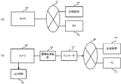
- FIG. 10A is a block diagram of a conventional network image monitoring system.
- 100 is an IP camera that outputs captured images to the network
- 101 is a network such as the Internet
- 102 is an image recording device that records images captured by the IP camera 100
- 103 is the camera 10. 0 or a PC that controls the recording apparatus 102 or browses images.
- the IP camera 100 images a subject and outputs the image to the network 101.
- the output image is input to the image recording apparatus 102 and the PC 103, the image recording apparatus 102 records the image, and the PC 103 displays the image.
- An image that captures a monitor image regardless of whether it is daytime or nighttime using a camera that captures a color image as a color camera during daytime or in a bright place, and a monochrome image as a near-infrared camera during nighttime or in a dark place.
- Surveillance systems are also widespread.
- a conventional image monitoring system regardless of whether it is daytime or nighttime will be described below.
- FIG. 10B is a block diagram of a conventional image monitoring system regardless of whether it is daytime or nighttime.
- 10 4 is a day / night camera that picks up a color image and a monochrome image by attaching / detaching a near-infrared cut filter
- 105 is an LED illumination that irradiates near-infrared light
- 106 is a predetermined image process applied to the image acquired by the day / night camera.
- An image processing device to be applied 107 an encoder that converts the image-processed image into a signal suitable for a network and outputs the signal, 108 a network such as the Internet, 109 an image recording device that records an image captured by the day / night camera 104 1 10 is a P for controlling the day / night camera 104 and the recording device 109 and viewing images.
- the near-infrared cut filter is used to cut off the infrared rays, and the infrared rays are cut from the incident light to pick up the incident light in the visible light region. This is because many imaging units have sensitivity in the visible light region and the near-infrared region, and a normal color image cannot be obtained if both visible light and near-infrared light are imaged simultaneously.
- the near-infrared cut filter is removed and the incident light in the infrared region is imaged.
- LED illumination 105 that irradiates near-infrared light may be used due to sensitivity and illumination.
- the day / night camera 104 When imaging a daytime or bright place, the day / night camera 104 is equipped with a near-infrared cut filter to capture the subject and output a color image. On the other hand, when imaging a night or dark place, the day / night camera 104 removes the near infrared cut filter, the LED illumination 105 emits light in synchronization with the shutter speed of the day / night camera 104, and the day / night camera 104 The subject is imaged and a monochrome image is output. The image output from the day / night camera 104 is subjected to predetermined image processing by the image processing device 106, converted into a signal format suitable for the network by the encoder 107, and output to the network. The output image is input to the image recording apparatus 102 and the PC 103, and the image recording apparatus 102 records the image, and the PC 103 displays the image.
- a network image monitoring system in which an image of a camera is transmitted via a network and recorded on a recording device and displayed on a display device (see Patent Document 1).
- a near-infrared illumination unit is used in a camera that captures a color image as a color camera during daytime or in a bright place, and takes a monochrome image as a near-infrared camera using a near-infrared irradiation unit during night or in a dark place.
- a technique for disposing red light emission inconspicuously by installing a white light illuminating unit in the vicinity of is disclosed (see Patent Document 2).
- the present invention has been made to solve such problems, and it is an object of the present invention to provide an image monitoring system that can be operated even in a place where a network cannot be constructed and has excellent portability.
- An image monitoring system includes a camera including an imaging unit that captures an image of a subject and outputs the image, an encryption unit that encrypts the image, and a control unit that controls the imaging unit and the encryption unit.
- a detachable recording medium that records an image acquired by the camera and a control unit that controls the recording medium, and the camera and the recording apparatus are connected by a cable. It is characterized by that.
- the acquired image is encrypted using a secret key in the encryption unit, and the recording device collects a plurality of encrypted images.
- the file is recorded as the recording medium.
- the camera of the present invention includes an imaging unit that captures an image of a subject and outputs an image, a filter unit that attaches and detaches an infrared cut filter, a lighting unit that includes a plurality of light emitters and irradiates near infrared light, A control unit that controls the imaging unit, the filter unit, and the illumination unit, and the control unit controls to extract the infrared cut filter when it is bright and acquires an image, and when it is dark, infrared control is performed.
- a cut filter is inserted, and the illumination unit is controlled to emit light according to the shutter timing of the imaging unit.
- the camera is characterized in that the control unit controls light emission amounts or directivities of the plurality of light emitters of the illumination unit according to a distance between the camera and the subject.
- the camera is characterized in that the wavelength of light emitted from the illumination unit is about 875 nm.
- the camera is characterized in that a visible light cut filter is attached to the illumination unit.
- FIG. 1 is a block diagram of a monitoring system according to an embodiment of the present invention.
- reference numeral 10 denotes a visible image when a daytime or bright place is used and outputs a color image, and a near-infrared ray is taken when a night or dark place is used to produce a monochrome image.
- An output camera, 11 an LED illumination that irradiates near-infrared light toward a subject when used at night or in a dark place, 20 an image recording device that records an image captured by the camera 10, and 24 an HDD (Hard disk drive) ) And SSD (Solid State Drive) or the like is a detachable large capacity recording unit.
- the camera 10 is preferably a megapixel camera using an imaging unit having a large number of effective pixels.
- the camera 10 is attached to a pillar / signpost or a veranda of a private house installed on the road or the like with the angle of view adjusted, and the recording device 20 is installed within the reach of the cable.
- illumination is described here as LED, other light sources may be used as long as near infrared light can be irradiated.
- the camera 10 When imaging a daytime or bright place, the camera 10 attaches a near-infrared cut filter to image a subject and outputs a color image. On the other hand, when imaging a night or dark place, the camera 10 removes the near-infrared cut filter, the LED illumination 11 irradiates the subject with near-infrared light in synchronization with the shutter speed of the camera 10, and the camera 10 reflects on the subject. Imaging near-infrared light and outputting a monochrome image.
- An image output from the camera 10 is input to the recording device via a dedicated cable.
- any dedicated cable, communication format, and signal format may be used, and TCP / IP or a unique protocol may be used.
- the image recording device 20 receives the image and records it in the recording unit 24.
- the image monitoring system consists of only a camera and an image recording device, and the system can be minimized by connecting each directly with a dedicated cable. An excellent image monitoring system can be provided.
- 30 and 50 are PCs
- 31 and 51 are dedicated viewer software
- 40 is a network.
- the recorded image can be viewed by removing the recording unit 24 and connecting to the PC 30 in which the dedicated viewer software 31 is installed.
- an image recorded on the recording device 20 via the network can be displayed on the PC 50 on which the dedicated viewer software 51 is installed in the same manner as in a normal network type monitoring system. You can browse.
- FIG. 2 is an internal block diagram of the camera of the surveillance system according to the embodiment of the present invention.
- 11 is the LED illumination described above
- 12 is a control unit for controlling each part of the camera 10
- 13 is a lens
- 14 is a filter unit that attaches / detaches the near-infrared cut filter or switches between the near-infrared cut filter and the visible light cut filter
- 15 is an imaging unit that receives light from the subject that has passed through the lens 13 and the filter unit, and outputs an image
- 16 An image compression unit that compresses an image output from the imaging unit 15 in a predetermined compression format
- 17 is an encryption unit that encrypts the compressed image using a predetermined method
- 18 is a network I / F that exchanges signals with the outside. It is.
- the near-infrared cut filter switching mechanism may be provided in the lens, or may be provided in front of the imaging unit separately from the lens.
- a near-infrared cut filter is inserted in the filter unit 14 under the control of the control unit 12, light from the subject enters through the lens 13, and near-infrared light is cut by the filter unit 14. Thus, only visible light is incident on the imaging unit 15 and a color image is output.
- the filter unit 14 removes the near-infrared cut filter or the near-infrared cut filter and the visible light cut filter are switched under the control of the control unit 12, and the shutter speed of the imaging unit 15 is changed.
- the LED illumination 11 irradiates the subject with near infrared light. Light from the subject enters through the lens 13 and the filter unit 1 In 4, the incident light passes through as it is, or the visible light is cut by the visible light cut filter and enters the imaging unit 15, and a monochrome image is output.
- the image output from the imaging unit 15 is input to the image compression unit 16, and JPEG (Joint Photog
- JPEG Joint Photog
- the image is compressed using a compression method such as raphic Experts Group.
- a compression method If emphasis is placed on image evidence, PNG (Portable Network Graphics) or GIF (Graph It is desirable to use a reversible compression method in which the data before compression and the data that has undergone compression / decompression processing are completely equal, such as ics Interchange Format).
- the compressed image is input to the encryption unit 17 and encrypted by a predetermined method.
- the encrypted image is converted into a signal in a format suitable for a dedicated cable by the network I / F and output.
- the wavelength range of light generally called visible light is approximately 360 nm to 830 nm according to the definition of JIS-Z8120, and visible light having a wavelength longer than 620 nm looks red to human eyes.
- the wavelength range of light called near infrared rays is approximately 700 to 2500 nm, which is close to that of visible light.
- illumination such as LEDs
- red light may be seen even though it is desired to irradiate and sneak a shot so as not to be noticed of a breaching vehicle or the like.
- the best sensitivity of the CCD is about 700 nm, and after that, the sensitivity becomes worse as the wavelength becomes longer. It is necessary to use light having a wavelength that balances sensitivity with sensitivity.
- the amount of visible light included is changed to 1 / n by changing the near-infrared light irradiated by near-infrared LED illumination having a peak value at, for example, 850 nm to near-infrared LED illumination having a peak value at, for example, 875 nm. It decreases to about 4 and red light becomes almost invisible, 875 nm It can be said that the light has a wavelength that balances red light reduction and sensitivity.
- a visible light cut filter is attached to the LED illumination 11 or the LED illumination window 82 described later while keeping the wavelength of near infrared light emitted by the LED illumination 11 as it is.
- a visible light cut filter that removes visible light having a wavelength of 830 nm or less is provided and illumination light having a peak value at 850 nm is irradiated, only near infrared light having a wavelength longer than 830 nm is irradiated toward the subject. Become. Thereby, when the light irradiated from the LED illumination 11 passes through the visible light cut filter, the visible light is removed, only the near-infrared light is irradiated to the subject, and the red light becomes almost invisible.
- irradiating near-infrared light by the method (a) or (b) reduces the red light visible from the subject and makes it difficult to notice the subject.
- the possibility that an image can be acquired increases.
- the LED illumination 11 is controlled so that a plurality of LEDs are arranged to emit light all at once or sequentially. At this time, it is desirable to adjust the light emission amount according to the distance between the camera 10 and the range to be imaged and the subject. For example, assuming that a total of 77 LEDs are attached to the LED illumination 11, three modes L, M, and H are set according to the distance as shown in the following table. In mode L, 35 LEDs are lit to illuminate a distance of 10 to 15 m from the camera 10. In mode M, 49 L to illuminate a distance of 15-20 m from the camera 10 Make ED emit light. In mode H, 7 to illuminate a distance of 20 to 25 m from the camera 10 Seven LEDs are caused to emit light. In this way, the system can be installed and operated with a higher degree of freedom by switching modes according to the distance between the camera and the range to be imaged and the subject.
- the light emission amount can be adjusted by controlling the magnitude of the power applied to the LED illumination 11. If you want to image far away, increase the power, and if you want to image near, lower the power.
- the irradiation distance can be adjusted by focusing / diffusing the irradiation range of the LED illumination 11. In this case, various methods are conceivable for adjusting the focusing / diffusion, and as an example, it can be adjusted by providing a reflector around the LED and moving the LED back and forth.
- the modes described above are merely examples, the number of modes may be set to any number, and the corresponding distance and the number of corresponding LEDs can be arbitrarily set. Also, the irradiation range can be arbitrarily set.
- FIG. 3 is an internal block diagram of the recording apparatus of the monitoring system according to the embodiment of the present invention.
- 21 Is a network I / F that exchanges signals with the outside
- 22 is a control unit that controls each unit of the image recording apparatus 20
- 23 is an LED light emitting unit that displays the state of the image recording apparatus 20 in its light emitting state
- 2 Reference numeral 4 denotes the above-described recording unit
- reference numeral 25 denotes a detachable monitor for viewing an image recorded in the recording unit
- reference numeral 26 denotes an input AC power source converted to a DC power source and supplied to each unit of the image recording apparatus 20.
- a power supply unit 27 is an uninterruptible power supply unit that supplies power to each unit or a specific part of the image recording apparatus 20 in place of the power supply unit 26 when power supply to the power supply unit 26 is interrupted.
- the network I / F 21 receives the image transmitted from the camera 10 via the dedicated cable, converts the signal format, and outputs the image to the recording unit 24.
- the received images are randomly synthesized and recorded for each of a plurality of images under the control of the control unit 22. This recording method will be described in detail later.
- the monitor 25 is connected to the control unit 22 and the synthesized image is decomposed and viewed using dedicated viewer software.
- the control unit 22 monitors the state of each unit of the image recording apparatus 20, controls the LED light emitting unit 23 according to the state, and the LED light emitting unit 23 emits light according to the state.
- the color is changed or turned on / flashing / turned off according to the power on / off state, the remaining amount, and the remaining recording capacity of the recording unit 24.
- the power supply unit 26 may convert AC power supplied from the outside into DC power, supply the power to each unit in the recording apparatus 10, and supply the power to the camera 10 via a dedicated cable.
- the camera 10 does not need to be provided with an external power input unit, but may be operated without power supply from the recording device 20 by providing the camera 10 with an external power input unit.
- the power supply unit 26 may be a storage battery, a solar power generator, or the like.
- the uninterruptible power supply unit 27 is connected to the power supply 2 6 may be provided to supply power to the recording device 20 in the event of a failure of 6 or when the power supply from the outside is cut off. You may make it supply to.
- the uninterruptible power supply unit 27 can prevent malfunction of each device and loss of recorded images.
- FIG. 4 is a schematic diagram showing a state of image encryption of the monitoring system according to the embodiment of the present invention.
- An image acquired by the camera 10 is encrypted by an encryption unit 17 in the camera 10 by setting an 8-bit secret key in advance.
- the encrypted image is randomly synthesized for each of a plurality of images in the recording device 20 and recorded in the recording unit 24 as an image A.
- the sheets are combined in a sequence of nine sheets.
- the synthesized image A is separated into the original nine images, and further 8 bi
- the public key of t is input and decrypted to display the image. Thereby, even if it is going to browse an image with PC etc. in which exclusive viewer software is not installed, an image cannot be displayed and high secrecy can be realized.
- FIG. 5 is an image browsing screen of the monitoring system according to the embodiment of the present invention.
- 60 is a browsing screen
- 61 is an image display unit for displaying an image
- 62 is a search operation unit for searching for a desired image by specifying a date and time
- 63 is for displaying a selected image.
- a selected image display unit 64 is a search result display unit 64 that displays thumbnails of the search results according to the conditions input by the search operation unit 62
- 65 is an operation such as play, pause, fast forward, rewind, skip, etc.
- Playback instruction button to be performed 66 is a zoom magnification change button for operating the enlargement / reduction of the image, 67 is a detection button for displaying the moving object detection result, 68 is a snapshot button for saving the image as a snapshot, 69 is an image This is a time advance button for switching the image displayed on the image display unit 61 by adjusting the acquired time.
- the search operation unit 62 displays a calendar and a time axis, and the background is colored on the day when the recorded image is present.
- the time when the recorded image is on the time axis is displayed, and the recorded images of that day are displayed as thumbnails in the search result display section 64 in time series.
- a desired image in the search result display unit 64 is selected, an image corresponding to the selected image display unit is displayed.
- the selected recorded image is reproduced as a video on the image display unit 61.
- the playback image can be played back, paused, fast forwarded, rewound, skipped, etc. by the playback instruction button 65, and the desired position pointed by the zoom magnification change button 66 can be zoomed up or zoomed out.
- the reproduced video indicates the moving object, for example, by surrounding it with a frame.
- the snapshot button 68 captures and records the video at a desired timing as a snapshot. be able to.
- a calendar is displayed on the search operation unit 62, and the background is colored on the day when there is a recorded image.
- the recorded image of the day is displayed on the image display unit 61, and operations such as playback, pause, fast forward, rewind, and skip can be performed as a video using the playback instruction button 65.
- the recorded image of the operated time is displayed on the image display unit 61 by clicking the left and right arrows or dragging and scrolling the portion representing the selected time at the center using the time advance button 69.
- the snapshot button 68 can capture and record a video at a desired timing as a snapshot.
- the image display unit 61 may display a live video currently acquired by an operation.
- FIG. 6 is a moving object detection setting screen of the monitoring system according to the embodiment of the present invention.
- 70 is a moving object detection setting screen
- 71 is an image display unit
- 72 is a detection ON / OFF setting unit that switches on / off of moving object detection
- 73 is a detection area setting unit that sets an area for detecting moving object
- 74 is a detection sensitivity setting unit for setting detection sensitivity for each area set by the detection area setting unit 73
- Reference numeral 5 denotes a detection display setting unit that sets a display method of a moving object detection result.
- the detection ON / OFF setting unit 72 applies a condition by selecting “ON” or “OFF” from the pull-down menu to determine whether or not to detect a moving object, and pressing a setting button.
- the detection area setting unit 73 sets the area of the image within a desired range, and sets detection valid / invalid for each area. Further, the set area and detection valid / invalid for each area are displayed on the image display unit 71. In this embodiment, the area is set to be divided into seven areas, but the area may be set to any number, and the size can be changed variously.
- the detection sensitivity setting unit 74 sets the detection sensitivity of the moving object detection area set by the detection area setting unit 73.
- a superimposition display method and a display duration on the image of the detection area are selected from a pull-down menu, and the condition is applied by pressing a setting button.
- continuous recording that is continuously recorded may be used, recording that is linked to motion detection may be performed, recording is normally performed at a low frame rate, and recording is performed at a high recording rate during motion detection. Also good.
- FIG. 7 is a perspective view of the camera of the surveillance system according to the embodiment of the present invention.
- (A) is a camera when the camera unit (lens and imaging unit) and LED illumination are arranged horizontally
- (B) is a camera when the camera and LED illumination are arranged vertically.
- 81 is a camera window for taking light into the lens 13 inside the camera 10
- 82 is an LED illumination 11 inside the camera 10.
- LED illumination windows 82 and 83 for transmitting light emitted from the camera 10 are grips for carrying the camera 10.
- the camera 10 is provided with a sunshade cover from the upper surface to the side surface so that unnecessary light (direct light from the sun or illumination light such as a streetlight) does not enter the camera window 81.
- heat radiating fins are provided on the left and right side surfaces and the bottom surface of the camera 10, so that heat generated inside can be efficiently radiated.
- a handle 83 is provided on the ceiling surface of the camera 10, which is convenient for carrying.
- a heater glass may be used for the camera window 81 and the LED illumination window 82 to prevent condensation, and a visible light cut filter may be attached to the LED illumination window 82.
- FIG. 8 is a horizontal sectional view of the camera of the surveillance system according to the embodiment of the present invention.
- 84 is a handle portion for opening the rear door
- 85 is a connector portion for connecting a cable for exchanging signals and power with the outside of the camera
- 86 is a heat dissipating heat of the substrate on which the LED is provided.
- the radiating fins 87 are fans that send wind toward the radiating fins 86.
- the camera 10 Since the camera 10 has a sealed structure, heat is easily generated inside. Therefore, the heat radiation effect is enhanced by attaching the heat radiation fins 86 to the back side of the substrate on which the LEDs that generate particularly large heat are provided, and further blowing the wind toward the heat radiation fins 86 by the fans 87.
- the blown wind hits the heat radiating fins 86 and absorbs heat, flows in the vertical direction inside the camera 10, flows further backward, and is again absorbed by the fan and discharged to circulate.
- the heated wind circulates while transferring heat to the inner wall surface of the camera 10 to cool the wind, and the heat transferred to the wall surface of the camera 10 is radiated to the outside air.
- camera 1 Efficient heat dissipation becomes possible by providing the heat radiating fins on the outer wall surface of 0.
- the internal configuration of the camera 10 corresponds to both (A) and (B) of FIG.
- FIG. 9 is a perspective view of the recording apparatus of the monitoring system according to the embodiment of the present invention.
- 91 is a recording apparatus housing
- 92 is a door for opening and closing the recording apparatus housing
- 93 is the recording apparatus 20.
- Reference numeral 5 denotes a lock portion for preventing others from opening when the door portion 92 is closed
- 96 is the recording device 2.
- Legs for supporting the recording device 20 when standing 0, 97 a connector portion for connecting a cable for exchanging signals and power with the outside of the recording device 20, and 98 a recording device when the recording device 20 is laid down 20 is a leg portion that supports 20.
- the recording apparatus housing 91 and the door 92 are connected to each other using a hinge or the like on one side, and the door 92 is closed and sealed by rotating around the connected side as an axis. Further, by closing the key with the lock portion 95, the recording device 20 cannot be opened by others.
- a handle portion 93 is provided on the ceiling surface of the recording apparatus 20, which is convenient for carrying.
- housings of the camera 10 and the recording apparatus 20 are made of, for example, aluminum, stainless steel, copper, plastic, or the like.
- the present invention is not limited to the above-described embodiments as they are, and can be embodied by modifying the components without departing from the scope of the invention in the implementation stage.
- various inventions can be formed by appropriately combining a plurality of constituent elements disclosed in the above embodiments. For example, some components may be deleted from all the components shown in each embodiment. Furthermore, you may combine suitably the component covering different embodiment.
Landscapes
- Engineering & Computer Science (AREA)
- Multimedia (AREA)
- Signal Processing (AREA)
- Health & Medical Sciences (AREA)
- Toxicology (AREA)
- Studio Devices (AREA)
- Closed-Circuit Television Systems (AREA)
- Television Signal Processing For Recording (AREA)
- Alarm Systems (AREA)
Priority Applications (2)
| Application Number | Priority Date | Filing Date | Title |
|---|---|---|---|
| CN201190000682.6U CN203445943U (zh) | 2010-08-20 | 2011-08-19 | 图像监视系统和照相机 |
| US13/817,353 US20130230294A1 (en) | 2010-08-20 | 2011-08-19 | Image monitoring system and camera |
Applications Claiming Priority (2)
| Application Number | Priority Date | Filing Date | Title |
|---|---|---|---|
| JP2010184943 | 2010-08-20 | ||
| JP2010-184943 | 2010-08-20 |
Publications (1)
| Publication Number | Publication Date |
|---|---|
| WO2012023603A1 true WO2012023603A1 (ja) | 2012-02-23 |
Family
ID=45605255
Family Applications (1)
| Application Number | Title | Priority Date | Filing Date |
|---|---|---|---|
| PCT/JP2011/068759 Ceased WO2012023603A1 (ja) | 2010-08-20 | 2011-08-19 | 画像監視システムおよびカメラ |
Country Status (4)
| Country | Link |
|---|---|
| US (1) | US20130230294A1 (https=) |
| JP (1) | JP5921112B2 (https=) |
| CN (2) | CN203445943U (https=) |
| WO (1) | WO2012023603A1 (https=) |
Families Citing this family (15)
| Publication number | Priority date | Publication date | Assignee | Title |
|---|---|---|---|---|
| KR101349560B1 (ko) * | 2012-04-26 | 2014-01-10 | 엘지이노텍 주식회사 | 적외선 카메라 및 이의 동작 방법 |
| IL223225A (en) * | 2012-11-25 | 2013-11-28 | Eliahu Antopolsky | Meetings documentation system that allows access to documentation with the consent of participants only |
| JP6471953B2 (ja) * | 2014-05-23 | 2019-02-20 | パナソニックIpマネジメント株式会社 | 撮像装置、撮像システム、及び撮像方法 |
| CN106572293A (zh) * | 2015-10-09 | 2017-04-19 | 阔展科技(深圳)有限公司 | 具红外led灯摄影机之省电方法及装置 |
| CN105323492A (zh) * | 2015-12-08 | 2016-02-10 | 上海斐讯数据通信技术有限公司 | 一种取景装置及相机和拍摄方法 |
| JP2017182331A (ja) * | 2016-03-29 | 2017-10-05 | シー・ティ・マシン株式会社 | 車番認識装置 |
| EP3328051B1 (en) * | 2016-11-29 | 2019-01-02 | Axis AB | Method for controlling an infrared cut filter of a video camera |
| KR101917329B1 (ko) * | 2017-11-03 | 2018-11-13 | 주식회사 엘리소프트 | 열 방출이 원활한 구조를 가지는 ip 카메라 및 이를 이용한 객체 검지 시스템 |
| WO2019181168A1 (ja) * | 2018-03-23 | 2019-09-26 | 富士フイルム株式会社 | 光配向膜の形成方法及び積層体の製造方法 |
| JP6690106B1 (ja) * | 2019-03-26 | 2020-04-28 | エスゼット ディージェイアイ テクノロジー カンパニー リミテッドSz Dji Technology Co.,Ltd | 決定装置、撮像システム、及び移動体 |
| JP7323787B2 (ja) * | 2019-07-31 | 2023-08-09 | 日亜化学工業株式会社 | 照明装置及び赤外線カメラ付き照明装置 |
| US10861127B1 (en) * | 2019-09-17 | 2020-12-08 | Gopro, Inc. | Image and video processing using multiple pipelines |
| JP7140819B2 (ja) * | 2020-12-25 | 2022-09-21 | 本田技研工業株式会社 | 撮像装置 |
| CN114827479B (zh) * | 2022-06-29 | 2022-09-27 | 深圳比特微电子科技有限公司 | 一种监控设备的工作模式切换方法和装置 |
| US12604072B2 (en) | 2023-11-21 | 2026-04-14 | Dell Products L.P. | Camera and infrared sensor shutter |
Citations (3)
| Publication number | Priority date | Publication date | Assignee | Title |
|---|---|---|---|---|
| JPH11252504A (ja) * | 1998-03-05 | 1999-09-17 | Casio Comput Co Ltd | 画像のセキュリテイシステム,電子カメラ装置および画像処理装置 |
| JP2003319158A (ja) * | 2002-04-18 | 2003-11-07 | Toshiyuki Tani | 画像処理システム |
| JP2009200577A (ja) * | 2008-02-19 | 2009-09-03 | Teac Corp | 画像記録装置 |
Family Cites Families (16)
| Publication number | Priority date | Publication date | Assignee | Title |
|---|---|---|---|---|
| JPH03162091A (ja) * | 1989-11-20 | 1991-07-12 | Fujitsu General Ltd | 集合住宅の画像・音声伝送装置 |
| JP3242822B2 (ja) * | 1995-10-06 | 2001-12-25 | シャープ株式会社 | テレビインターホン装置 |
| JP4097773B2 (ja) * | 1998-04-20 | 2008-06-11 | オリンパス株式会社 | デジタル画像編集システム |
| JP3450801B2 (ja) * | 2000-05-31 | 2003-09-29 | キヤノン株式会社 | 瞳孔位置検出装置及び方法、視点位置検出装置及び方法、並びに立体画像表示システム |
| JP2002084451A (ja) * | 2000-09-11 | 2002-03-22 | Minolta Co Ltd | デジタル撮像装置、画像処理システム、記録媒体、およびデジタル撮像方法 |
| JP3670952B2 (ja) * | 2000-10-19 | 2005-07-13 | 三洋電機株式会社 | カラー/白黒切換カメラ |
| JP2002271688A (ja) * | 2001-03-09 | 2002-09-20 | Hitachi Kokusai Electric Inc | テレビジョンカメラ |
| JP2003075893A (ja) * | 2001-09-06 | 2003-03-12 | Murakami Corp | 車両用周囲撮像装置 |
| DE10146959A1 (de) * | 2001-09-24 | 2003-04-30 | Hella Kg Hueck & Co | Nachtsichtvorrichtung für Fahrzeuge |
| JP2003134245A (ja) * | 2001-10-22 | 2003-05-09 | Matsushita Electric Ind Co Ltd | インターホンシステム |
| JP2003319381A (ja) * | 2002-04-23 | 2003-11-07 | Matsushita Electric Works Ltd | 監視システム |
| JP2005348056A (ja) * | 2004-06-02 | 2005-12-15 | Sharp Corp | テレビインタホン装置 |
| WO2007111317A1 (ja) * | 2006-03-28 | 2007-10-04 | Kyocera Corporation | 暗視装置 |
| JP4939901B2 (ja) * | 2006-11-02 | 2012-05-30 | 富士フイルム株式会社 | 距離画像生成方法及びその装置 |
| JP5196985B2 (ja) * | 2007-12-19 | 2013-05-15 | キヤノン株式会社 | カメラシステム及び撮像装置 |
| JP4209926B1 (ja) * | 2008-01-09 | 2009-01-14 | 株式会社庄内クリエート工業 | 近赤外線を用いた包装食品の検査装置 |
-
2011
- 2011-08-19 US US13/817,353 patent/US20130230294A1/en not_active Abandoned
- 2011-08-19 CN CN201190000682.6U patent/CN203445943U/zh not_active Expired - Fee Related
- 2011-08-19 CN CN201320494996.7U patent/CN203827454U/zh not_active Expired - Fee Related
- 2011-08-19 JP JP2011179447A patent/JP5921112B2/ja active Active
- 2011-08-19 WO PCT/JP2011/068759 patent/WO2012023603A1/ja not_active Ceased
Patent Citations (3)
| Publication number | Priority date | Publication date | Assignee | Title |
|---|---|---|---|---|
| JPH11252504A (ja) * | 1998-03-05 | 1999-09-17 | Casio Comput Co Ltd | 画像のセキュリテイシステム,電子カメラ装置および画像処理装置 |
| JP2003319158A (ja) * | 2002-04-18 | 2003-11-07 | Toshiyuki Tani | 画像処理システム |
| JP2009200577A (ja) * | 2008-02-19 | 2009-09-03 | Teac Corp | 画像記録装置 |
Also Published As
| Publication number | Publication date |
|---|---|
| JP2012065312A (ja) | 2012-03-29 |
| CN203445943U (zh) | 2014-02-19 |
| US20130230294A1 (en) | 2013-09-05 |
| JP5921112B2 (ja) | 2016-05-24 |
| CN203827454U (zh) | 2014-09-10 |
Similar Documents
| Publication | Publication Date | Title |
|---|---|---|
| JP5921112B2 (ja) | 画像監視システムおよびカメラ | |
| Caputo | Digital video surveillance and security | |
| CN102466945B (zh) | 标准人像采集装置中的led补光及人像剪裁评价系统 | |
| US7724280B2 (en) | Dual surveillance camera system | |
| US7719571B2 (en) | Wireless video surveillance system and method with DVR-based querying | |
| US7821533B2 (en) | Wireless video surveillance system and method with two-way locking of input capture devices | |
| US20060075235A1 (en) | Wireless video surveillance system and method with security key | |
| US20060070109A1 (en) | Wireless video surveillance system & method with rapid installation | |
| KR101439180B1 (ko) | 조명 융합형 무선 감시 카메라 시스템 | |
| US7719567B2 (en) | Wireless video surveillance system and method with emergency video access | |
| US20220284783A1 (en) | Security device, system, and method of using the same | |
| CN203457248U (zh) | 一种多功能报警摄像一体机 | |
| CN201974617U (zh) | 公安标准化人像采集系统中的led光源设备 | |
| US8208019B2 (en) | Wireless video surveillance system and method with external removable recording | |
| US7936370B2 (en) | Wireless video surveillance system and method with dual encoding | |
| JP5698104B2 (ja) | 録画一体型防犯用監視カメラ | |
| JP2006287893A (ja) | ネットワークカメラシステム | |
| KR101188564B1 (ko) | 협각렌즈와 광각렌즈를 이용한 폐쇄회로 카메라 시스템 및 그 구현방법 | |
| JP3205135U (ja) | 防犯カメラ付き街灯 | |
| CN112702572A (zh) | 一种人工智能的公共场所的网络安全监控装置 | |
| KR102413249B1 (ko) | 배터리의 효율적인 관리 기능을 가진 독립전원형 영상감시장치 및 그 시스템 | |
| KR20060111806A (ko) | 적외선엘이디가 구비되는 적외선카메라 | |
| KR100905055B1 (ko) | 고장 점검, 방범 및 비상 구조 요청 기능을 동시에 갖는다기능 보안등 | |
| KR200377900Y1 (ko) | 상태표시 기능을 갖는 cctv용 적외선 카메라 장치 | |
| CN207135179U (zh) | 一种具有红外夜视搜索功能的警用执法仪 |
Legal Events
| Date | Code | Title | Description |
|---|---|---|---|
| WWE | Wipo information: entry into national phase |
Ref document number: 201190000682.6 Country of ref document: CN |
|
| 121 | Ep: the epo has been informed by wipo that ep was designated in this application |
Ref document number: 11818243 Country of ref document: EP Kind code of ref document: A1 |
|
| NENP | Non-entry into the national phase |
Ref country code: DE |
|
| WWE | Wipo information: entry into national phase |
Ref document number: 13817353 Country of ref document: US |
|
| 122 | Ep: pct application non-entry in european phase |
Ref document number: 11818243 Country of ref document: EP Kind code of ref document: A1 |