WO2012023603A1 - 画像監視システムおよびカメラ - Google Patents
画像監視システムおよびカメラ Download PDFInfo
- Publication number
- WO2012023603A1 WO2012023603A1 PCT/JP2011/068759 JP2011068759W WO2012023603A1 WO 2012023603 A1 WO2012023603 A1 WO 2012023603A1 JP 2011068759 W JP2011068759 W JP 2011068759W WO 2012023603 A1 WO2012023603 A1 WO 2012023603A1
- Authority
- WO
- WIPO (PCT)
- Prior art keywords
- image
- camera
- unit
- light
- monitoring system
- Prior art date
Links
Images


Classifications
-
- H—ELECTRICITY
- H04—ELECTRIC COMMUNICATION TECHNIQUE
- H04N—PICTORIAL COMMUNICATION, e.g. TELEVISION
- H04N7/00—Television systems
- H04N7/18—Closed-circuit television [CCTV] systems, i.e. systems in which the video signal is not broadcast
-
- H—ELECTRICITY
- H04—ELECTRIC COMMUNICATION TECHNIQUE
- H04N—PICTORIAL COMMUNICATION, e.g. TELEVISION
- H04N23/00—Cameras or camera modules comprising electronic image sensors; Control thereof
- H04N23/70—Circuitry for compensating brightness variation in the scene
- H04N23/74—Circuitry for compensating brightness variation in the scene by influencing the scene brightness using illuminating means
-
- H—ELECTRICITY
- H04—ELECTRIC COMMUNICATION TECHNIQUE
- H04N—PICTORIAL COMMUNICATION, e.g. TELEVISION
- H04N5/00—Details of television systems
- H04N5/30—Transforming light or analogous information into electric information
- H04N5/33—Transforming infrared radiation
-
- H—ELECTRICITY
- H04—ELECTRIC COMMUNICATION TECHNIQUE
- H04N—PICTORIAL COMMUNICATION, e.g. TELEVISION
- H04N5/00—Details of television systems
- H04N5/76—Television signal recording
- H04N5/765—Interface circuits between an apparatus for recording and another apparatus
- H04N5/77—Interface circuits between an apparatus for recording and another apparatus between a recording apparatus and a television camera
-
- H—ELECTRICITY
- H04—ELECTRIC COMMUNICATION TECHNIQUE
- H04N—PICTORIAL COMMUNICATION, e.g. TELEVISION
- H04N9/00—Details of colour television systems
- H04N9/79—Processing of colour television signals in connection with recording
- H04N9/80—Transformation of the television signal for recording, e.g. modulation, frequency changing; Inverse transformation for playback
- H04N9/804—Transformation of the television signal for recording, e.g. modulation, frequency changing; Inverse transformation for playback involving pulse code modulation of the colour picture signal components
- H04N9/8042—Transformation of the television signal for recording, e.g. modulation, frequency changing; Inverse transformation for playback involving pulse code modulation of the colour picture signal components involving data reduction
Definitions
- the present invention relates to a portable image monitoring system in which a camera and a recording device are carried and installed at a desired place, and an image is captured and recorded.
- the image monitoring system is installed in various public facilities such as hotels, buildings, convenience store financial institutions, dams or roads for the purpose of crime prevention, post-verification, and accident prevention.
- the monitoring target area is imaged with a camera or the like,
- the captured image is transmitted to a monitoring center such as a management office or a security room, and the supervisor monitors the monitoring target by the transmitted image, and gives a caution or warning according to the purpose or necessity. Record It was something to save.
- network-type image monitoring forms in which images from surveillance cameras are digitized and transmitted and monitored via a network represented by the Internet have become widespread.
- a conventional network type image monitoring system will be described below.
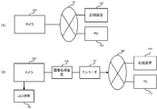
- FIG. 10A is a block diagram of a conventional network image monitoring system.
- 100 is an IP camera that outputs captured images to the network
- 101 is a network such as the Internet
- 102 is an image recording device that records images captured by the IP camera 100
- 103 is the camera 10. 0 or a PC that controls the recording apparatus 102 or browses images.
- the IP camera 100 images a subject and outputs the image to the network 101.
- the output image is input to the image recording apparatus 102 and the PC 103, the image recording apparatus 102 records the image, and the PC 103 displays the image.
- An image that captures a monitor image regardless of whether it is daytime or nighttime using a camera that captures a color image as a color camera during daytime or in a bright place, and a monochrome image as a near-infrared camera during nighttime or in a dark place.
- Surveillance systems are also widespread.
- a conventional image monitoring system regardless of whether it is daytime or nighttime will be described below.
- FIG. 10B is a block diagram of a conventional image monitoring system regardless of whether it is daytime or nighttime.
- 10 4 is a day / night camera that picks up a color image and a monochrome image by attaching / detaching a near-infrared cut filter
- 105 is an LED illumination that irradiates near-infrared light
- 106 is a predetermined image process applied to the image acquired by the day / night camera.
- An image processing device to be applied 107 an encoder that converts the image-processed image into a signal suitable for a network and outputs the signal, 108 a network such as the Internet, 109 an image recording device that records an image captured by the day / night camera 104 1 10 is a P for controlling the day / night camera 104 and the recording device 109 and viewing images.
- the near-infrared cut filter is used to cut off the infrared rays, and the infrared rays are cut from the incident light to pick up the incident light in the visible light region. This is because many imaging units have sensitivity in the visible light region and the near-infrared region, and a normal color image cannot be obtained if both visible light and near-infrared light are imaged simultaneously.
- the near-infrared cut filter is removed and the incident light in the infrared region is imaged.
- LED illumination 105 that irradiates near-infrared light may be used due to sensitivity and illumination.
- the day / night camera 104 When imaging a daytime or bright place, the day / night camera 104 is equipped with a near-infrared cut filter to capture the subject and output a color image. On the other hand, when imaging a night or dark place, the day / night camera 104 removes the near infrared cut filter, the LED illumination 105 emits light in synchronization with the shutter speed of the day / night camera 104, and the day / night camera 104 The subject is imaged and a monochrome image is output. The image output from the day / night camera 104 is subjected to predetermined image processing by the image processing device 106, converted into a signal format suitable for the network by the encoder 107, and output to the network. The output image is input to the image recording apparatus 102 and the PC 103, and the image recording apparatus 102 records the image, and the PC 103 displays the image.
- a network image monitoring system in which an image of a camera is transmitted via a network and recorded on a recording device and displayed on a display device (see Patent Document 1).
- a near-infrared illumination unit is used in a camera that captures a color image as a color camera during daytime or in a bright place, and takes a monochrome image as a near-infrared camera using a near-infrared irradiation unit during night or in a dark place.
- a technique for disposing red light emission inconspicuously by installing a white light illuminating unit in the vicinity of is disclosed (see Patent Document 2).
- the present invention has been made to solve such problems, and it is an object of the present invention to provide an image monitoring system that can be operated even in a place where a network cannot be constructed and has excellent portability.
- An image monitoring system includes a camera including an imaging unit that captures an image of a subject and outputs the image, an encryption unit that encrypts the image, and a control unit that controls the imaging unit and the encryption unit.
- a detachable recording medium that records an image acquired by the camera and a control unit that controls the recording medium, and the camera and the recording apparatus are connected by a cable. It is characterized by that.
- the acquired image is encrypted using a secret key in the encryption unit, and the recording device collects a plurality of encrypted images.
- the file is recorded as the recording medium.
- the camera of the present invention includes an imaging unit that captures an image of a subject and outputs an image, a filter unit that attaches and detaches an infrared cut filter, a lighting unit that includes a plurality of light emitters and irradiates near infrared light, A control unit that controls the imaging unit, the filter unit, and the illumination unit, and the control unit controls to extract the infrared cut filter when it is bright and acquires an image, and when it is dark, infrared control is performed.
- a cut filter is inserted, and the illumination unit is controlled to emit light according to the shutter timing of the imaging unit.
- the camera is characterized in that the control unit controls light emission amounts or directivities of the plurality of light emitters of the illumination unit according to a distance between the camera and the subject.
- the camera is characterized in that the wavelength of light emitted from the illumination unit is about 875 nm.
- the camera is characterized in that a visible light cut filter is attached to the illumination unit.
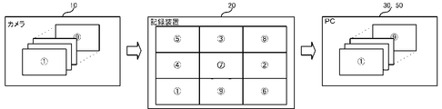
- FIG. 1 is a block diagram of a monitoring system according to an embodiment of the present invention.
- reference numeral 10 denotes a visible image when a daytime or bright place is used and outputs a color image, and a near-infrared ray is taken when a night or dark place is used to produce a monochrome image.
- An output camera, 11 an LED illumination that irradiates near-infrared light toward a subject when used at night or in a dark place, 20 an image recording device that records an image captured by the camera 10, and 24 an HDD (Hard disk drive) ) And SSD (Solid State Drive) or the like is a detachable large capacity recording unit.
- the camera 10 is preferably a megapixel camera using an imaging unit having a large number of effective pixels.
- the camera 10 is attached to a pillar / signpost or a veranda of a private house installed on the road or the like with the angle of view adjusted, and the recording device 20 is installed within the reach of the cable.
- illumination is described here as LED, other light sources may be used as long as near infrared light can be irradiated.
- the camera 10 When imaging a daytime or bright place, the camera 10 attaches a near-infrared cut filter to image a subject and outputs a color image. On the other hand, when imaging a night or dark place, the camera 10 removes the near-infrared cut filter, the LED illumination 11 irradiates the subject with near-infrared light in synchronization with the shutter speed of the camera 10, and the camera 10 reflects on the subject. Imaging near-infrared light and outputting a monochrome image.
- An image output from the camera 10 is input to the recording device via a dedicated cable.
- any dedicated cable, communication format, and signal format may be used, and TCP / IP or a unique protocol may be used.
- the image recording device 20 receives the image and records it in the recording unit 24.
- the image monitoring system consists of only a camera and an image recording device, and the system can be minimized by connecting each directly with a dedicated cable. An excellent image monitoring system can be provided.
- 30 and 50 are PCs
- 31 and 51 are dedicated viewer software
- 40 is a network.
- the recorded image can be viewed by removing the recording unit 24 and connecting to the PC 30 in which the dedicated viewer software 31 is installed.
- an image recorded on the recording device 20 via the network can be displayed on the PC 50 on which the dedicated viewer software 51 is installed in the same manner as in a normal network type monitoring system. You can browse.
- FIG. 2 is an internal block diagram of the camera of the surveillance system according to the embodiment of the present invention.
- 11 is the LED illumination described above
- 12 is a control unit for controlling each part of the camera 10
- 13 is a lens
- 14 is a filter unit that attaches / detaches the near-infrared cut filter or switches between the near-infrared cut filter and the visible light cut filter
- 15 is an imaging unit that receives light from the subject that has passed through the lens 13 and the filter unit, and outputs an image
- 16 An image compression unit that compresses an image output from the imaging unit 15 in a predetermined compression format
- 17 is an encryption unit that encrypts the compressed image using a predetermined method
- 18 is a network I / F that exchanges signals with the outside. It is.
- the near-infrared cut filter switching mechanism may be provided in the lens, or may be provided in front of the imaging unit separately from the lens.
- a near-infrared cut filter is inserted in the filter unit 14 under the control of the control unit 12, light from the subject enters through the lens 13, and near-infrared light is cut by the filter unit 14. Thus, only visible light is incident on the imaging unit 15 and a color image is output.
- the filter unit 14 removes the near-infrared cut filter or the near-infrared cut filter and the visible light cut filter are switched under the control of the control unit 12, and the shutter speed of the imaging unit 15 is changed.
- the LED illumination 11 irradiates the subject with near infrared light. Light from the subject enters through the lens 13 and the filter unit 1 In 4, the incident light passes through as it is, or the visible light is cut by the visible light cut filter and enters the imaging unit 15, and a monochrome image is output.
- the image output from the imaging unit 15 is input to the image compression unit 16, and JPEG (Joint Photog
- JPEG Joint Photog
- the image is compressed using a compression method such as raphic Experts Group.
- a compression method If emphasis is placed on image evidence, PNG (Portable Network Graphics) or GIF (Graph It is desirable to use a reversible compression method in which the data before compression and the data that has undergone compression / decompression processing are completely equal, such as ics Interchange Format).
- the compressed image is input to the encryption unit 17 and encrypted by a predetermined method.
- the encrypted image is converted into a signal in a format suitable for a dedicated cable by the network I / F and output.
- the wavelength range of light generally called visible light is approximately 360 nm to 830 nm according to the definition of JIS-Z8120, and visible light having a wavelength longer than 620 nm looks red to human eyes.
- the wavelength range of light called near infrared rays is approximately 700 to 2500 nm, which is close to that of visible light.
- illumination such as LEDs
- red light may be seen even though it is desired to irradiate and sneak a shot so as not to be noticed of a breaching vehicle or the like.
- the best sensitivity of the CCD is about 700 nm, and after that, the sensitivity becomes worse as the wavelength becomes longer. It is necessary to use light having a wavelength that balances sensitivity with sensitivity.
- the amount of visible light included is changed to 1 / n by changing the near-infrared light irradiated by near-infrared LED illumination having a peak value at, for example, 850 nm to near-infrared LED illumination having a peak value at, for example, 875 nm. It decreases to about 4 and red light becomes almost invisible, 875 nm It can be said that the light has a wavelength that balances red light reduction and sensitivity.
- a visible light cut filter is attached to the LED illumination 11 or the LED illumination window 82 described later while keeping the wavelength of near infrared light emitted by the LED illumination 11 as it is.
- a visible light cut filter that removes visible light having a wavelength of 830 nm or less is provided and illumination light having a peak value at 850 nm is irradiated, only near infrared light having a wavelength longer than 830 nm is irradiated toward the subject. Become. Thereby, when the light irradiated from the LED illumination 11 passes through the visible light cut filter, the visible light is removed, only the near-infrared light is irradiated to the subject, and the red light becomes almost invisible.
- irradiating near-infrared light by the method (a) or (b) reduces the red light visible from the subject and makes it difficult to notice the subject.
- the possibility that an image can be acquired increases.
- the LED illumination 11 is controlled so that a plurality of LEDs are arranged to emit light all at once or sequentially. At this time, it is desirable to adjust the light emission amount according to the distance between the camera 10 and the range to be imaged and the subject. For example, assuming that a total of 77 LEDs are attached to the LED illumination 11, three modes L, M, and H are set according to the distance as shown in the following table. In mode L, 35 LEDs are lit to illuminate a distance of 10 to 15 m from the camera 10. In mode M, 49 L to illuminate a distance of 15-20 m from the camera 10 Make ED emit light. In mode H, 7 to illuminate a distance of 20 to 25 m from the camera 10 Seven LEDs are caused to emit light. In this way, the system can be installed and operated with a higher degree of freedom by switching modes according to the distance between the camera and the range to be imaged and the subject.
- the light emission amount can be adjusted by controlling the magnitude of the power applied to the LED illumination 11. If you want to image far away, increase the power, and if you want to image near, lower the power.
- the irradiation distance can be adjusted by focusing / diffusing the irradiation range of the LED illumination 11. In this case, various methods are conceivable for adjusting the focusing / diffusion, and as an example, it can be adjusted by providing a reflector around the LED and moving the LED back and forth.
- the modes described above are merely examples, the number of modes may be set to any number, and the corresponding distance and the number of corresponding LEDs can be arbitrarily set. Also, the irradiation range can be arbitrarily set.
- FIG. 3 is an internal block diagram of the recording apparatus of the monitoring system according to the embodiment of the present invention.
- 21 Is a network I / F that exchanges signals with the outside
- 22 is a control unit that controls each unit of the image recording apparatus 20
- 23 is an LED light emitting unit that displays the state of the image recording apparatus 20 in its light emitting state
- 2 Reference numeral 4 denotes the above-described recording unit
- reference numeral 25 denotes a detachable monitor for viewing an image recorded in the recording unit
- reference numeral 26 denotes an input AC power source converted to a DC power source and supplied to each unit of the image recording apparatus 20.
- a power supply unit 27 is an uninterruptible power supply unit that supplies power to each unit or a specific part of the image recording apparatus 20 in place of the power supply unit 26 when power supply to the power supply unit 26 is interrupted.
- the network I / F 21 receives the image transmitted from the camera 10 via the dedicated cable, converts the signal format, and outputs the image to the recording unit 24.
- the received images are randomly synthesized and recorded for each of a plurality of images under the control of the control unit 22. This recording method will be described in detail later.
- the monitor 25 is connected to the control unit 22 and the synthesized image is decomposed and viewed using dedicated viewer software.
- the control unit 22 monitors the state of each unit of the image recording apparatus 20, controls the LED light emitting unit 23 according to the state, and the LED light emitting unit 23 emits light according to the state.
- the color is changed or turned on / flashing / turned off according to the power on / off state, the remaining amount, and the remaining recording capacity of the recording unit 24.
- the power supply unit 26 may convert AC power supplied from the outside into DC power, supply the power to each unit in the recording apparatus 10, and supply the power to the camera 10 via a dedicated cable.
- the camera 10 does not need to be provided with an external power input unit, but may be operated without power supply from the recording device 20 by providing the camera 10 with an external power input unit.
- the power supply unit 26 may be a storage battery, a solar power generator, or the like.
- the uninterruptible power supply unit 27 is connected to the power supply 2 6 may be provided to supply power to the recording device 20 in the event of a failure of 6 or when the power supply from the outside is cut off. You may make it supply to.
- the uninterruptible power supply unit 27 can prevent malfunction of each device and loss of recorded images.
- FIG. 4 is a schematic diagram showing a state of image encryption of the monitoring system according to the embodiment of the present invention.
- An image acquired by the camera 10 is encrypted by an encryption unit 17 in the camera 10 by setting an 8-bit secret key in advance.
- the encrypted image is randomly synthesized for each of a plurality of images in the recording device 20 and recorded in the recording unit 24 as an image A.
- the sheets are combined in a sequence of nine sheets.
- the synthesized image A is separated into the original nine images, and further 8 bi
- the public key of t is input and decrypted to display the image. Thereby, even if it is going to browse an image with PC etc. in which exclusive viewer software is not installed, an image cannot be displayed and high secrecy can be realized.
- FIG. 5 is an image browsing screen of the monitoring system according to the embodiment of the present invention.
- 60 is a browsing screen
- 61 is an image display unit for displaying an image
- 62 is a search operation unit for searching for a desired image by specifying a date and time
- 63 is for displaying a selected image.
- a selected image display unit 64 is a search result display unit 64 that displays thumbnails of the search results according to the conditions input by the search operation unit 62
- 65 is an operation such as play, pause, fast forward, rewind, skip, etc.
- Playback instruction button to be performed 66 is a zoom magnification change button for operating the enlargement / reduction of the image, 67 is a detection button for displaying the moving object detection result, 68 is a snapshot button for saving the image as a snapshot, 69 is an image This is a time advance button for switching the image displayed on the image display unit 61 by adjusting the acquired time.
- the search operation unit 62 displays a calendar and a time axis, and the background is colored on the day when the recorded image is present.
- the time when the recorded image is on the time axis is displayed, and the recorded images of that day are displayed as thumbnails in the search result display section 64 in time series.
- a desired image in the search result display unit 64 is selected, an image corresponding to the selected image display unit is displayed.
- the selected recorded image is reproduced as a video on the image display unit 61.
- the playback image can be played back, paused, fast forwarded, rewound, skipped, etc. by the playback instruction button 65, and the desired position pointed by the zoom magnification change button 66 can be zoomed up or zoomed out.
- the reproduced video indicates the moving object, for example, by surrounding it with a frame.
- the snapshot button 68 captures and records the video at a desired timing as a snapshot. be able to.
- a calendar is displayed on the search operation unit 62, and the background is colored on the day when there is a recorded image.
- the recorded image of the day is displayed on the image display unit 61, and operations such as playback, pause, fast forward, rewind, and skip can be performed as a video using the playback instruction button 65.
- the recorded image of the operated time is displayed on the image display unit 61 by clicking the left and right arrows or dragging and scrolling the portion representing the selected time at the center using the time advance button 69.
- the snapshot button 68 can capture and record a video at a desired timing as a snapshot.
- the image display unit 61 may display a live video currently acquired by an operation.
- FIG. 6 is a moving object detection setting screen of the monitoring system according to the embodiment of the present invention.
- 70 is a moving object detection setting screen
- 71 is an image display unit
- 72 is a detection ON / OFF setting unit that switches on / off of moving object detection
- 73 is a detection area setting unit that sets an area for detecting moving object
- 74 is a detection sensitivity setting unit for setting detection sensitivity for each area set by the detection area setting unit 73
- Reference numeral 5 denotes a detection display setting unit that sets a display method of a moving object detection result.
- the detection ON / OFF setting unit 72 applies a condition by selecting “ON” or “OFF” from the pull-down menu to determine whether or not to detect a moving object, and pressing a setting button.
- the detection area setting unit 73 sets the area of the image within a desired range, and sets detection valid / invalid for each area. Further, the set area and detection valid / invalid for each area are displayed on the image display unit 71. In this embodiment, the area is set to be divided into seven areas, but the area may be set to any number, and the size can be changed variously.
- the detection sensitivity setting unit 74 sets the detection sensitivity of the moving object detection area set by the detection area setting unit 73.
- a superimposition display method and a display duration on the image of the detection area are selected from a pull-down menu, and the condition is applied by pressing a setting button.
- continuous recording that is continuously recorded may be used, recording that is linked to motion detection may be performed, recording is normally performed at a low frame rate, and recording is performed at a high recording rate during motion detection. Also good.
- FIG. 7 is a perspective view of the camera of the surveillance system according to the embodiment of the present invention.
- (A) is a camera when the camera unit (lens and imaging unit) and LED illumination are arranged horizontally
- (B) is a camera when the camera and LED illumination are arranged vertically.
- 81 is a camera window for taking light into the lens 13 inside the camera 10
- 82 is an LED illumination 11 inside the camera 10.
- LED illumination windows 82 and 83 for transmitting light emitted from the camera 10 are grips for carrying the camera 10.
- the camera 10 is provided with a sunshade cover from the upper surface to the side surface so that unnecessary light (direct light from the sun or illumination light such as a streetlight) does not enter the camera window 81.
- heat radiating fins are provided on the left and right side surfaces and the bottom surface of the camera 10, so that heat generated inside can be efficiently radiated.
- a handle 83 is provided on the ceiling surface of the camera 10, which is convenient for carrying.
- a heater glass may be used for the camera window 81 and the LED illumination window 82 to prevent condensation, and a visible light cut filter may be attached to the LED illumination window 82.
- FIG. 8 is a horizontal sectional view of the camera of the surveillance system according to the embodiment of the present invention.
- 84 is a handle portion for opening the rear door
- 85 is a connector portion for connecting a cable for exchanging signals and power with the outside of the camera
- 86 is a heat dissipating heat of the substrate on which the LED is provided.
- the radiating fins 87 are fans that send wind toward the radiating fins 86.
- the camera 10 Since the camera 10 has a sealed structure, heat is easily generated inside. Therefore, the heat radiation effect is enhanced by attaching the heat radiation fins 86 to the back side of the substrate on which the LEDs that generate particularly large heat are provided, and further blowing the wind toward the heat radiation fins 86 by the fans 87.
- the blown wind hits the heat radiating fins 86 and absorbs heat, flows in the vertical direction inside the camera 10, flows further backward, and is again absorbed by the fan and discharged to circulate.
- the heated wind circulates while transferring heat to the inner wall surface of the camera 10 to cool the wind, and the heat transferred to the wall surface of the camera 10 is radiated to the outside air.
- camera 1 Efficient heat dissipation becomes possible by providing the heat radiating fins on the outer wall surface of 0.
- the internal configuration of the camera 10 corresponds to both (A) and (B) of FIG.
- FIG. 9 is a perspective view of the recording apparatus of the monitoring system according to the embodiment of the present invention.
- 91 is a recording apparatus housing
- 92 is a door for opening and closing the recording apparatus housing
- 93 is the recording apparatus 20.
- Reference numeral 5 denotes a lock portion for preventing others from opening when the door portion 92 is closed
- 96 is the recording device 2.
- Legs for supporting the recording device 20 when standing 0, 97 a connector portion for connecting a cable for exchanging signals and power with the outside of the recording device 20, and 98 a recording device when the recording device 20 is laid down 20 is a leg portion that supports 20.
- the recording apparatus housing 91 and the door 92 are connected to each other using a hinge or the like on one side, and the door 92 is closed and sealed by rotating around the connected side as an axis. Further, by closing the key with the lock portion 95, the recording device 20 cannot be opened by others.
- a handle portion 93 is provided on the ceiling surface of the recording apparatus 20, which is convenient for carrying.
- housings of the camera 10 and the recording apparatus 20 are made of, for example, aluminum, stainless steel, copper, plastic, or the like.
- the present invention is not limited to the above-described embodiments as they are, and can be embodied by modifying the components without departing from the scope of the invention in the implementation stage.
- various inventions can be formed by appropriately combining a plurality of constituent elements disclosed in the above embodiments. For example, some components may be deleted from all the components shown in each embodiment. Furthermore, you may combine suitably the component covering different embodiment.
Abstract
Description
可搬型の画像監視システムに関するものである。
等といった様々な公共施設等において、犯罪抑止や事後検証、事故防止等の目的で設置さ
れている。従来の一般的な画像監視システムでは、カメラ等で監視対象エリアを撮像し、
撮像された画像を管理事務所や警備室等の監視センタに伝送し、監視者が、伝送されてく
る画像により監視対象を監視し、目的や必要に応じて注意や警告をしたり、画像を記録・
保存したりするものであった。近年は、監視カメラの画像をデジタル化し、インターネ
ットに代表されるネットワークを介して、画像を伝送し監視を行うネットワーク型の画像
監視形態が普及してきている。以下に従来のネットワーク型の画像監視システムを説明す
る。
した画像をネットワークへ出力するIPカメラ、101はインターネット等のネットワー
ク、102はIPカメラ100が撮像した画像を記録する画像記録装置、103はカメラ10
0や記録装置102を制御したり画像を閲覧したりするPCである。
れた画像は画像記録装置102やPC103に入力され、画像記録装置102では画像が
記録され、PC103では画像を表示する。
暗い場所の撮影時には近赤外線カメラとしてモノクロ画像を撮像するカメラを
用いて、昼夜明暗を問わず監視画像を取得する画像監視システムも普及している。以下に
、従来の昼夜明暗を問わない画像監視システムについて説明する。
4は近赤外線カットフィルタを着脱させてカラー画像とモノクロ画像を撮像するデイ/ナ
イトカメラ、105は近赤外線光を照射するLED照明、106はデイ/ナイトカメラが
取得した画像に所定の画像処理を施す画像処理装置、107は画像処理後の画像をネット
ワークに適した信号に変換して出力するエンコーダ、108はインターネット等のネット
ワーク、109はデイ/ナイトカメラ104が撮像した画像を記録する画像記録装置、1
10はデイ/ナイトカメラ104や記録装置109を制御したり画像を閲覧したりするP
Cである。
装置に表示させるネットワーク画像監視システムが開示されている(特許文献1参照)。
暗い場所の撮影時には近赤外線照射部を用いてモノクロで近赤外線カメラとしてモノクロ
画像を撮像するカメラにおいて、近赤外線照明部の付近に白色光照明部を設置し、赤い発
光を目立たなくする技術が開示されている(特許文献2参照)。
IPアドレスを振り当て、カメラと記録装置は固定された場所に設置することが通常であ
り、ネットワーク網を構築できない場所では運用出来ない問題がある。また、設置場所を
度々変更して運用したい場合に、機器の撤去、搬送、設置に多大な負荷がかかる。
い場所でも運用でき、可搬性に優れた画像監視システムを提供することを目的とする。
暗号化する暗号化部と、前記撮像部および暗号化部を制御する制御部と、を備えるカメラ
と、前記カメラで取得した画像を記録する着脱可能な記録媒体と、前記記録媒体を制御す
る制御部と、を備える記録装置と、から構成され、前記カメラと前記記録装置とはケーブ
ルで接続されることを特徴とする。
て秘密鍵を用いて暗号化され、前記記録装置では、前記暗号化された画像を複数纏めて1
のファイルとして前記記録媒体として記録することを特徴とする
ィルタを着脱するフィルタ部と、複数の発光体を備え、近赤外線光を照射する照明部と、
前記撮像部、前記フィルタ部および前記照明部を制御する制御部と、を備え、前記制御部
は、明るい時には、前記赤外線カットフィルタを抜去して画像を取得する様に制御し、暗
い時には、赤外線カットフィルタを挿入し、前記撮像部のシャッタータイミングに合わせ
て前記照明部を発光させる様に制御することを特徴とする。
特徴とすることを特徴とする。
徴とする。
に優れた画像監視システムを提供することができる。
施例である監視システムのブロック図である。
専用ケーブルで接続することでシステムを最小限にできるため、ネットワーク網を構築で
きない場所でも運用でき、可搬性に優れた画像監視システムを提供できる。
、40はネットワークである。本システムでは、記録部24を取り外し、専用のビューア
ソフト31がインストールされたPC30と接続することで、記録された画像を閲覧する
ことができる。
また、専用ケーブルを分配し、ネットワーク40に接続することで、通常のネットワー
ク型の監視システムと同様に専用のビューアソフト51がインストールされたPC50で
ネットワークを介し
て記録装置20に記録された画像を閲覧することができる。
11は上述したLED照明、12はカメラ10の各部を制御する制御部、13はレンズ、
14は近赤外線カットフィルタの着脱または近赤外線カットフィルタと可視光カットフィ
ルタを切り替えるフィルタ部、15はレンズ13およびフィルタ部を通過した被写体から
の光を受光して画像を出力する撮像部、16は撮像部15から出力された画像を所定の圧
縮形式で圧縮する画像圧縮部、17は圧縮された画像を所定の方式で暗号化する暗号化部
、18は外部と信号をやり取りするネットワークI/Fである。なお、近赤外線カットフ
ィルタの切り替え機構は、レンズ内に設けられていても良いし、レンズとは別に撮像部の
前に設けられても良い。
線カットフィルタが挿入され、レンズ13を介して被写体からの光が入射し、フィルタ部
14で近赤外線光がカットされて撮像部15に可視光のみが入射し、カラー画像を出力す
る。
赤外線カットフィルタが取り外され、または、近赤外線カットフィルタと可視光カットフ
ィルタが切り替わり、撮像部15のシャッタースピードに合わせてLED照明11は近赤
外線光を被写体に照射する。レンズ13を介して被写体からの光が入射し、フィルタ部1
4では入射光がそのまま通過して、または、可視光カットフィルタで可視光がカットされ
て撮像部15に入射し、モノクロ画像を出力する。
raphic Experts Group)等の圧縮方式で画像圧縮される。このとき、圧縮方式としては、
画像の証拠性を重視するならば、PNG(Portable Network Graphics)やGIF(Graph
ics Interchange Format)等の、圧縮前のデータと圧縮・展開の処理を経たデータが完全
に等しくなる可逆圧縮方式を用いることが望ましい。
画像はネットワークI/Fで専用ケーブルに適した形式の信号に変換され、出力される。
、おおよそ360nm~830nmであり、620nmより長い波長の可視光は人間の目
に赤く見える。また、近赤外線と呼ばれる光の波長域はおおよそ700~2500nmで
あり、可視光と近い性質を持っている。LED等の照明においては、近赤外線領域である
例えば850nmにピーク値を持つ波長の光を照射すると、プラスマイナス100nm程
度の波長の光も照射されるため、少なからず可視光も同時に照射されてしまうことになる
。すなわち、例えば違反車等に気付かれない様に照射して隠し撮りしたいのに、赤色の光
が見えてしまう場合があり、気付かれて証拠画像を撮像できない等の問題がある。かとい
って900nmや950nmにピーク値を持つ波長の光を照射すると、一般的にCCDの
最も良い感度は700nm程であり、これ以降は波長が長くなるほど感度が悪くなってし
まうため、赤色光低減と感度とのバランスが取れた波長の光を使用する必要がある。
なモノクロ画像を得るために、(イ)LED照明11の照射する光の波長を長くする方法
と、(ロ)可視光カットフィルタを挿入して可視光を除去する方法の2通りの方法が考え
られる。
線光を、例えば875nmにピーク値を持つ近赤外線LED照明に変更することで、含ま
れる可視光の量は1/4程度に減少し、赤色光はほとんど視認できなくなり、875nm
が赤色光低減と感度とのバランスが取れた波長の光であるといえる。
は後述するLED照明窓82に可視光カットフィルタを装着する。例えば、830nm以
下の波長の可視光を除去する可視光カットフィルタを設け、850nmにピーク値を持つ
照明光を照射すると、830nmより波長の長い近赤外線光のみが被写体に向けて照射さ
れることになる。これにより、LED照明11から照射される光が可視光カットフィルタ
を通過する際に可視光が除去され、近赤外線光のみが被写体に照射され、赤色光はほとん
ど視認できなくなる。
体から視認できる赤色光を低減し、被写体に気付かれにくくなるため、証拠画像として良
好なモノクロ画像を取得できる可能性が高くなる。
御される。このとき、カメラ10と撮像したい範囲および被写体との距離に応じて発光量を調
節することが望ましい。例えば、LED照明11には全部で77個のLEDが取り付けら
れているとして、以下の表に示す様に距離に応じて3つのモードL,M,Hが設定される
。モードLでは、カメラ10からの距離10~15mを照らすために35個のLEDを発
光させる。モードMでは、カメラ10からの距離15~20mを照らすために49個のL
EDを発光させる。モードHでは、カメラ10からの距離20~25mを照らすために7
7個のLEDを発光させる。この様にカメラと撮像したい範囲や被写体との距離に応じて
モードを切り替えることで、より自由度の高いシステムの設置・運用が可能となる。

または、LED照明11の照射範囲を集束/拡散させることで照射距離を調整することも可能である。この場合、集束/拡散を調整するためには種々の方法が考えられ、一例として、LEDの周囲に反射板を設けてLEDの位置を前後させる機構とすることで調整できる。
く、対応距離と対応LEDの個数も任意に設定できる。また、照射範囲についても任意に
設定することができる。
は外部と信号をやり取りするネットワークI/F、22は画像記録装置20の各部を制御
する制御部、23は画像記録装置20の状態をその発光状態で表示するLED発光部、2
4は上述した記録部、25は記録部24に記録された画像を閲覧するための着脱可能なモ
ニタ、26は入力されたAC電源をDC電源に変換して画像記録装置20の各部へ供給す
る電源部、27は電源部26への電源供給が遮断された際に電源部26に代わって画像記
録装置20の各部または特定の部位に電源を供給する無停電電源部である。
信し、信号形式を変換して記録部24へ画像を出力する。記録部24では、制御部22の
制御により、受信した画像を複数枚ごとにランダムに合成して記録する。この記録方法に
ついては後に詳述する。記録された画像を閲覧する場合は、制御部22にモニタ25を接
続し、専用のビューアソフトを用いて合成された画像を分解して閲覧する。また、制御部
22は画像記録装置20の各部の状態を監視し、その状態に応じてLED発光部23を制
御し、LED発光部23は状態に応じて発光する。例えば、ここでは電源のオン/オフ状
態や残量、記録部24の残り記録容量に応じて色の変化や点灯・点滅・消灯で表示する。
また、電源部26は、外部から供給されたAC電源をDC電源に変換し、記録装置10内
の各部に供給するとともに、専用ケーブルを介してカメラ10に供給する様にしても良い
。この場合にはカメラ10には別途外部電源入力部を設ける必要はないが、カメラ10に
外部電源入力部を設けて記録装置20からの電源供給なしで運用されても良い。なお、電
源部26は蓄電池や太陽光発電器等であっても良い。また、無停電電源部27は、電源2
6の故障や外部からの電源供給が遮断された場合に、記録装置20内に電源を供給するた
めに設けられ、各部に供給される様にしても良いが、最低限維持が必要な構成のみに供給
する様にしても良い。無停電電源部27により、各機器の故障や記録画像の損失を防ぐこ
とができる。
。
鍵を事前に設定して暗号化される。暗号化された画像は記録装置20内で複数枚ごとにラ
ンダムに合成されて、画像Aとして記録部24に記録される。本実施例では、例えば9枚
ずつ順番をバラバラにして合成される。そして、専用のビューアソフトがインストールさ
れたPCで閲覧する際に、合成された画像Aは元の9枚の画像に分離され、さらに8bi
tの公開鍵を入力し、復号化され画像が表示される。これにより、専用のビューアソフト
がインストールされていないPC等で画像を閲覧しようとしても画像を表示することがで
きず、高い秘匿性を実現することができる。
70は動体検知設定画面、71は画像表示部、72は動体検知のオン/オフを切り替える
検知ON/OFF設定部、73は動体検知するエリアを設定する検知エリア設定部、74
は検知エリア設定部73で設定したエリアごとに検知感度を設定する検知感度設定部、7
5は動体検知結果の表示方法を設定する検知表示設定部である。
ウンで選択し、設定ボタンを押下することで条件を適用する。検知エリア設定部73では
、画像のエリアを所望の範囲に設定し、エリアごとに検出の有効/無効を設定する。さら
に画像表示部71に設定したエリアとエリアごとの検出有効/無効を表示する。本実施例
ではエリアを7つに分割設定しているが、エリアはいくつに設定されても良く、その大き
さも様々に変更できる。検知感度設定部74では、検知エリア設定部73で設定した動体
検知エリアの検知感度を設定する。検知表示設定部75では、検知エリアの画像への重畳
表示方法と表示持続時間をプルダウンで選択し、設定ボタンを押下することで条件を適用
する。
した記録としても良いし、通常時には低いフレームレートで記録し、動体検知時には高い
記録レートで記録する様にしても良い。
カメラ部(レンズと撮像部)とLED照明を水平に配置した際のカメラで、(B)はカメ
ラとLED照明を垂直に配置した際のカメラである。図7において、81はカメラ10内
部のレンズ13に光を取り込むためのカメラ窓、82はカメラ10内部のLED照明11
から発せられる光を透過するためのLED照明窓82、83はカメラ10を持ち運ぶため
に掴む取っ手部である。
陽からの直接の光や街灯などの照明光)がカメラ窓81に入射しない様になっている。ま
た、カメラ10の左右の側面および底面には放熱フィンが設けられており、内部で発生し
た熱を効率よく放熱することができる。また、カメラ10の天井面には取っ手部83が設
けられており、持ち運ぶのに便利である。
られても良く、LED照明窓82には可視光カットフィルタが装着されても良い。
て、84は背面の扉を開くための取っ手部、85はカメラ10外部と信号や電力をやり取
りするためのケーブルを接続するコネクタ部、86はLEDが設けられた基板の熱を放熱
する放熱フィン、87は放熱フィン86に向かって風を送るファンである。
大きいLEDが設けられた基板の裏側に放熱フィン86を取り付け、さらにファン87に
よって放熱フィン86に向かって風を吹き付けることで放熱効果を高めている。吹き付け
られた風は放熱フィン86に当たって熱を吸収し、カメラ10内部の上下方向へ向かって
流れ、さらに後方へと流れ、再びファンに吸収されて排出されることで循環する。このと
き、熱を持った風はカメラ10の内側の壁面に熱を伝達しながら循環することで風が冷却
され、カメラ10の壁面に伝わった熱は外気へと放熱される。さらにこのとき、カメラ1
0の外側の壁面に放熱フィンが設けられていることで、効率の良い放熱が可能となる。
91は記録装置筺体、92は記録装置の筺体を開閉するための扉部、93は記録装置20
を持ち運ぶために掴む取っ手部、94はLED発光部23を覗き込めるLED表示窓、9
5は扉部92を閉じたときに他人に開かれないようにするための錠部、96は記録装置2
0を立て置きする場合に記録装置20を支える脚部、97は記録装置20外部と信号や電
力をやり取りするためのケーブルを接続するコネクタ部、98は記録装置20を寝かせて
おく場合に記録装置20を支える脚部である。
軸にして回動させることで扉部92を閉じ、密閉される。さらに錠部95で鍵を閉めるこ
とで他者に記録装置20を開けられることはなくなる。また、記録装置20の天井面には
取っ手部93が設けられており、持ち運ぶのに便利である。
材、プラスチック等で形成される。
一部説明したが、赤外線カットフィルタを切り替えるデイ・ナイトカメラの他にも通常の
カメラ等に用いることももちろん可能であり、その構成及び動作とその内容についても本
発明の要旨を逸脱しない範囲で種々に変形して実施できる。
その要旨を逸脱しない範囲で構成要素を変形して具体化できる。また、上記各実施形態に
開示されている複数の構成要素の適宜な組み合せにより種々の発明を形成できる。例えば
、各実施形態に示される全構成要素から幾つかの構成要素を削除してもよい。さらに、異
なる実施形態に亘る構成要素を適宜組み合せてもよい。
5:撮像部、16:画像圧縮部、17:暗号化部、18:ネットワークI/F、20:記
録装置、21:ネットワークI/F、22:制御部、23:LED発光部、24:記録部
、25:モニタ、26:電源、27:無停電電源部、30:PC、31:ビューアソフト
、40:ネットワーク、50:PC、51:ビューアソフト、60:閲覧画面、61:画
像表示部、62:検索操作部、63:選択画像表示部、64:検索結果表示部、65:再
生指示ボタン、66:ズーム倍率変更ボタン、67:検知ボタン、68:スナップショッ
トボタン、69:時間送りボタン、70:動体検知設定画面、71:画像表示部、72:検知ON/OFF設定部
、73:検知エリア設定部、74:検知感度設定部、75:検知表示設定部、81:カメ
ラ窓、82:LED照明窓、83:取っ手部、84:取っ手部、85:コネクタ部、86
:放熱フィン、87:ファン、91:記録装置筺体、92:扉部、93:取っ手部、94
:LED表示窓、95:錠部、96:脚部、97:コネクタ部、98:脚部。
Claims (6)
- 被写体を撮像して画像を出力する撮像部と、前記画像を暗号化する暗号化部と、前記撮像
部および暗号化部を制御する制御部と、を備えるカメラと、
前記カメラで取得した画像を記録する着脱可能な記録媒体と、前記記録媒体を制御する制
御部と、を備える記録装置と、から構成され、
前記カメラと前記記録装置とはケーブルで接続されることを特徴とする画像監視システム
。 - 請求項1に記載の画像監視システムにおいて、
前記カメラでは、取得した画像は前記暗号化部において秘密鍵を用いて暗号化され、
前記記録装置では、前記暗号化された画像を複数纏めて1のファイルとして前記記録媒体
として記録することを特徴とする画像監視システム。 - [規則91に基づく訂正 20.10.2011]
被写体を撮像して画像を出力する撮像部と、
赤外線カットフィルタを着脱するフィルタ部と、
複数の発光体を備え、近赤外線光を照射する照明部と、
前記撮像部、前記フィルタ部および前記照明部を制御する制御部と、を備え、
前記制御部は、明るい時には、前記赤外線カットフィルタを挿入して画像を取得する様に
制御し、
暗い時には、赤外線カットフィルタを抜去し、前記撮像部のシャッタータイミングに合わ
せて前記照明部を発光させる様に制御することを特徴とするカメラ。 - 請求項3に記載のカメラにおいて、
前記制御部は、前記カメラと前記被写体との距離に応じて、前記照明部の前記複数の発光体の発光量または指向性を制御することを特徴とするカメラ。 - 請求項3に記載のカメラにおいて、
前記照明部から照射される光の波長は約875nmであることを特徴とするカメラ - 請求項3に記載のカメラにおいて、
前記照明部には可視光カットフィルタが装着されていることを特徴とするカメラ
Priority Applications (2)
| Application Number | Priority Date | Filing Date | Title |
|---|---|---|---|
| US13/817,353 US20130230294A1 (en) | 2010-08-20 | 2011-08-19 | Image monitoring system and camera |
| CN201190000682.6U CN203445943U (zh) | 2010-08-20 | 2011-08-19 | 图像监视系统和照相机 |
Applications Claiming Priority (2)
| Application Number | Priority Date | Filing Date | Title |
|---|---|---|---|
| JP2010-184943 | 2010-08-20 | ||
| JP2010184943 | 2010-08-20 |
Publications (1)
| Publication Number | Publication Date |
|---|---|
| WO2012023603A1 true WO2012023603A1 (ja) | 2012-02-23 |
Family
ID=45605255
Family Applications (1)
| Application Number | Title | Priority Date | Filing Date |
|---|---|---|---|
| PCT/JP2011/068759 WO2012023603A1 (ja) | 2010-08-20 | 2011-08-19 | 画像監視システムおよびカメラ |
Country Status (4)
| Country | Link |
|---|---|
| US (1) | US20130230294A1 (ja) |
| JP (1) | JP5921112B2 (ja) |
| CN (2) | CN203445943U (ja) |
| WO (1) | WO2012023603A1 (ja) |
Families Citing this family (13)
| Publication number | Priority date | Publication date | Assignee | Title |
|---|---|---|---|---|
| KR101349560B1 (ko) * | 2012-04-26 | 2014-01-10 | 엘지이노텍 주식회사 | 적외선 카메라 및 이의 동작 방법 |
| IL223225A (en) * | 2012-11-25 | 2013-11-28 | Eliahu Antopolsky | Meetings documentation system that allows access to documentation with the consent of participants only |
| JP6471953B2 (ja) | 2014-05-23 | 2019-02-20 | パナソニックIpマネジメント株式会社 | 撮像装置、撮像システム、及び撮像方法 |
| CN106572293A (zh) * | 2015-10-09 | 2017-04-19 | 阔展科技(深圳)有限公司 | 具红外led灯摄影机之省电方法及装置 |
| CN105323492A (zh) * | 2015-12-08 | 2016-02-10 | 上海斐讯数据通信技术有限公司 | 一种取景装置及相机和拍摄方法 |
| JP2017182331A (ja) * | 2016-03-29 | 2017-10-05 | シー・ティ・マシン株式会社 | 車番認識装置 |
| EP3328051B1 (en) * | 2016-11-29 | 2019-01-02 | Axis AB | Method for controlling an infrared cut filter of a video camera |
| KR101917329B1 (ko) * | 2017-11-03 | 2018-11-13 | 주식회사 엘리소프트 | 열 방출이 원활한 구조를 가지는 ip 카메라 및 이를 이용한 객체 검지 시스템 |
| WO2019181168A1 (ja) * | 2018-03-23 | 2019-09-26 | 富士フイルム株式会社 | 光配向膜の形成方法及び積層体の製造方法 |
| JP6690106B1 (ja) * | 2019-03-26 | 2020-04-28 | エスゼット ディージェイアイ テクノロジー カンパニー リミテッドSz Dji Technology Co.,Ltd | 決定装置、撮像システム、及び移動体 |
| JP7323787B2 (ja) * | 2019-07-31 | 2023-08-09 | 日亜化学工業株式会社 | 照明装置及び赤外線カメラ付き照明装置 |
| US10861127B1 (en) * | 2019-09-17 | 2020-12-08 | Gopro, Inc. | Image and video processing using multiple pipelines |
| CN114827479B (zh) * | 2022-06-29 | 2022-09-27 | 深圳比特微电子科技有限公司 | 一种监控设备的工作模式切换方法和装置 |
Citations (3)
| Publication number | Priority date | Publication date | Assignee | Title |
|---|---|---|---|---|
| JPH11252504A (ja) * | 1998-03-05 | 1999-09-17 | Casio Comput Co Ltd | 画像のセキュリテイシステム,電子カメラ装置および画像処理装置 |
| JP2003319158A (ja) * | 2002-04-18 | 2003-11-07 | Toshiyuki Tani | 画像処理システム |
| JP2009200577A (ja) * | 2008-02-19 | 2009-09-03 | Teac Corp | 画像記録装置 |
Family Cites Families (16)
| Publication number | Priority date | Publication date | Assignee | Title |
|---|---|---|---|---|
| JPH03162091A (ja) * | 1989-11-20 | 1991-07-12 | Fujitsu General Ltd | 集合住宅の画像・音声伝送装置 |
| JP3242822B2 (ja) * | 1995-10-06 | 2001-12-25 | シャープ株式会社 | テレビインターホン装置 |
| JP4097773B2 (ja) * | 1998-04-20 | 2008-06-11 | オリンパス株式会社 | デジタル画像編集システム |
| JP3450801B2 (ja) * | 2000-05-31 | 2003-09-29 | キヤノン株式会社 | 瞳孔位置検出装置及び方法、視点位置検出装置及び方法、並びに立体画像表示システム |
| JP2002084451A (ja) * | 2000-09-11 | 2002-03-22 | Minolta Co Ltd | デジタル撮像装置、画像処理システム、記録媒体、およびデジタル撮像方法 |
| JP3670952B2 (ja) * | 2000-10-19 | 2005-07-13 | 三洋電機株式会社 | カラー/白黒切換カメラ |
| JP2002271688A (ja) * | 2001-03-09 | 2002-09-20 | Hitachi Kokusai Electric Inc | テレビジョンカメラ |
| JP2003075893A (ja) * | 2001-09-06 | 2003-03-12 | Murakami Corp | 車両用周囲撮像装置 |
| DE10146959A1 (de) * | 2001-09-24 | 2003-04-30 | Hella Kg Hueck & Co | Nachtsichtvorrichtung für Fahrzeuge |
| JP2003134245A (ja) * | 2001-10-22 | 2003-05-09 | Matsushita Electric Ind Co Ltd | インターホンシステム |
| JP2003319381A (ja) * | 2002-04-23 | 2003-11-07 | Matsushita Electric Works Ltd | 監視システム |
| JP2005348056A (ja) * | 2004-06-02 | 2005-12-15 | Sharp Corp | テレビインタホン装置 |
| JP4594423B2 (ja) * | 2006-03-28 | 2010-12-08 | 京セラ株式会社 | 暗視装置 |
| JP4939901B2 (ja) * | 2006-11-02 | 2012-05-30 | 富士フイルム株式会社 | 距離画像生成方法及びその装置 |
| JP5196985B2 (ja) * | 2007-12-19 | 2013-05-15 | キヤノン株式会社 | カメラシステム及び撮像装置 |
| JP4209926B1 (ja) * | 2008-01-09 | 2009-01-14 | 株式会社庄内クリエート工業 | 近赤外線を用いた包装食品の検査装置 |
-
2011
- 2011-08-19 WO PCT/JP2011/068759 patent/WO2012023603A1/ja active Application Filing
- 2011-08-19 JP JP2011179447A patent/JP5921112B2/ja active Active
- 2011-08-19 CN CN201190000682.6U patent/CN203445943U/zh not_active Expired - Fee Related
- 2011-08-19 US US13/817,353 patent/US20130230294A1/en not_active Abandoned
- 2011-08-19 CN CN201320494996.7U patent/CN203827454U/zh not_active Expired - Fee Related
Patent Citations (3)
| Publication number | Priority date | Publication date | Assignee | Title |
|---|---|---|---|---|
| JPH11252504A (ja) * | 1998-03-05 | 1999-09-17 | Casio Comput Co Ltd | 画像のセキュリテイシステム,電子カメラ装置および画像処理装置 |
| JP2003319158A (ja) * | 2002-04-18 | 2003-11-07 | Toshiyuki Tani | 画像処理システム |
| JP2009200577A (ja) * | 2008-02-19 | 2009-09-03 | Teac Corp | 画像記録装置 |
Also Published As
| Publication number | Publication date |
|---|---|
| US20130230294A1 (en) | 2013-09-05 |
| CN203827454U (zh) | 2014-09-10 |
| CN203445943U (zh) | 2014-02-19 |
| JP5921112B2 (ja) | 2016-05-24 |
| JP2012065312A (ja) | 2012-03-29 |
Similar Documents
| Publication | Publication Date | Title |
|---|---|---|
| JP5921112B2 (ja) | 画像監視システムおよびカメラ | |
| CN102466945B (zh) | 标准人像采集装置中的led补光及人像剪裁评价系统 | |
| Kruegle | CCTV Surveillance: Video practices and technology | |
| Caputo | Digital video surveillance and security | |
| US8253796B2 (en) | Wireless video surveillance system and method with rapid installation | |
| CN100508598C (zh) | 双监视摄像机系统 | |
| US7719571B2 (en) | Wireless video surveillance system and method with DVR-based querying | |
| US7821533B2 (en) | Wireless video surveillance system and method with two-way locking of input capture devices | |
| US20060075235A1 (en) | Wireless video surveillance system and method with security key | |
| WO2015147573A1 (ko) | 조명 융합형 무선 감시 카메라 시스템 | |
| US20060072757A1 (en) | Wireless video surveillance system and method with emergency video access | |
| US8208019B2 (en) | Wireless video surveillance system and method with external removable recording | |
| JP2006287893A (ja) | ネットワークカメラシステム | |
| US7936370B2 (en) | Wireless video surveillance system and method with dual encoding | |
| JP2009060261A (ja) | 映像監視システム | |
| KR101600425B1 (ko) | 아이피 스피드 돔 카메라 | |
| KR101188564B1 (ko) | 협각렌즈와 광각렌즈를 이용한 폐쇄회로 카메라 시스템 및 그 구현방법 | |
| JP5698104B2 (ja) | 録画一体型防犯用監視カメラ | |
| JP2011090581A (ja) | 交通信号機や防犯灯などの路上設置機器と一体型であるプライバシー保護機能付防犯カメラシステム | |
| KR102413249B1 (ko) | 배터리의 효율적인 관리 기능을 가진 독립전원형 영상감시장치 및 그 시스템 | |
| CN216526725U (zh) | 360度全景影像变焦显示的摄影机 | |
| US11393309B1 (en) | Security device, system, and method of using the same | |
| KR100905055B1 (ko) | 고장 점검, 방범 및 비상 구조 요청 기능을 동시에 갖는다기능 보안등 | |
| KR200377900Y1 (ko) | 상태표시 기능을 갖는 cctv용 적외선 카메라 장치 | |
| TWI392339B (zh) | 監控系統及監控方法 |
Legal Events
| Date | Code | Title | Description |
|---|---|---|---|
| WWE | Wipo information: entry into national phase |
Ref document number: 201190000682.6 Country of ref document: CN |
|
| 121 | Ep: the epo has been informed by wipo that ep was designated in this application |
Ref document number: 11818243 Country of ref document: EP Kind code of ref document: A1 |
|
| NENP | Non-entry into the national phase |
Ref country code: DE |
|
| WWE | Wipo information: entry into national phase |
Ref document number: 13817353 Country of ref document: US |
|
| 122 | Ep: pct application non-entry in european phase |
Ref document number: 11818243 Country of ref document: EP Kind code of ref document: A1 |