WO2012014869A1 - インプリント装置及びインプリント転写方法 - Google Patents
インプリント装置及びインプリント転写方法 Download PDFInfo
- Publication number
- WO2012014869A1 WO2012014869A1 PCT/JP2011/066918 JP2011066918W WO2012014869A1 WO 2012014869 A1 WO2012014869 A1 WO 2012014869A1 JP 2011066918 W JP2011066918 W JP 2011066918W WO 2012014869 A1 WO2012014869 A1 WO 2012014869A1
- Authority
- WO
- WIPO (PCT)
- Prior art keywords
- back surface
- pressurization
- stamper
- transfer
- imprint
- Prior art date
- Legal status (The legal status is an assumption and is not a legal conclusion. Google has not performed a legal analysis and makes no representation as to the accuracy of the status listed.)
- Ceased
Links
Images



Classifications
-
- G—PHYSICS
- G03—PHOTOGRAPHY; CINEMATOGRAPHY; ANALOGOUS TECHNIQUES USING WAVES OTHER THAN OPTICAL WAVES; ELECTROGRAPHY; HOLOGRAPHY
- G03F—PHOTOMECHANICAL PRODUCTION OF TEXTURED OR PATTERNED SURFACES, e.g. FOR PRINTING, FOR PROCESSING OF SEMICONDUCTOR DEVICES; MATERIALS THEREFOR; ORIGINALS THEREFOR; APPARATUS SPECIALLY ADAPTED THEREFOR
- G03F7/00—Photomechanical, e.g. photolithographic, production of textured or patterned surfaces, e.g. printing surfaces; Materials therefor, e.g. comprising photoresists; Apparatus specially adapted therefor
- G03F7/0002—Lithographic processes using patterning methods other than those involving the exposure to radiation, e.g. by stamping
-
- B—PERFORMING OPERATIONS; TRANSPORTING
- B29—WORKING OF PLASTICS; WORKING OF SUBSTANCES IN A PLASTIC STATE IN GENERAL
- B29C—SHAPING OR JOINING OF PLASTICS; SHAPING OF MATERIAL IN A PLASTIC STATE, NOT OTHERWISE PROVIDED FOR; AFTER-TREATMENT OF THE SHAPED PRODUCTS, e.g. REPAIRING
- B29C43/00—Compression moulding, i.e. applying external pressure to flow the moulding material; Apparatus therefor
- B29C43/02—Compression moulding, i.e. applying external pressure to flow the moulding material; Apparatus therefor of articles of definite length, i.e. discrete articles
- B29C43/021—Compression moulding, i.e. applying external pressure to flow the moulding material; Apparatus therefor of articles of definite length, i.e. discrete articles characterised by the shape of the surface
-
- B—PERFORMING OPERATIONS; TRANSPORTING
- B29—WORKING OF PLASTICS; WORKING OF SUBSTANCES IN A PLASTIC STATE IN GENERAL
- B29C—SHAPING OR JOINING OF PLASTICS; SHAPING OF MATERIAL IN A PLASTIC STATE, NOT OTHERWISE PROVIDED FOR; AFTER-TREATMENT OF THE SHAPED PRODUCTS, e.g. REPAIRING
- B29C43/00—Compression moulding, i.e. applying external pressure to flow the moulding material; Apparatus therefor
- B29C43/02—Compression moulding, i.e. applying external pressure to flow the moulding material; Apparatus therefor of articles of definite length, i.e. discrete articles
- B29C43/10—Isostatic pressing, i.e. using non-rigid pressure-exerting members against rigid parts or dies
-
- B—PERFORMING OPERATIONS; TRANSPORTING
- B82—NANOTECHNOLOGY
- B82Y—SPECIFIC USES OR APPLICATIONS OF NANOSTRUCTURES; MEASUREMENT OR ANALYSIS OF NANOSTRUCTURES; MANUFACTURE OR TREATMENT OF NANOSTRUCTURES
- B82Y10/00—Nanotechnology for information processing, storage or transmission, e.g. quantum computing or single electron logic
-
- B—PERFORMING OPERATIONS; TRANSPORTING
- B82—NANOTECHNOLOGY
- B82Y—SPECIFIC USES OR APPLICATIONS OF NANOSTRUCTURES; MEASUREMENT OR ANALYSIS OF NANOSTRUCTURES; MANUFACTURE OR TREATMENT OF NANOSTRUCTURES
- B82Y40/00—Manufacture or treatment of nanostructures
Definitions
- the present invention relates to an imprint apparatus and an imprint transfer method in which a stamper having a particularly fine unevenness on a surface and a transferred object are pressurized and the uneven shape of the stamper is transferred to the surface of the transferred object.
- an imprint technique for performing fine pattern formation at low cost has been proposed.
- a stamper having irregularities (surface shape) corresponding to the irregularities of a pattern to be formed is embossed on a transfer object obtained by forming a resin layer on a predetermined substrate, for example.
- a fine pattern can be formed on the resin layer of the transfer object.
- the imprint technique is being studied for application to the formation of a recording bit pattern on a large-capacity recording medium such as a hard disk or the formation of a pattern of a semiconductor integrated circuit.
- a stamper In an imprint apparatus in a manufacturing process of a recording medium such as a hard disk, a stamper is required as a pattern master to be transferred.
- a stamper In the stamper manufacturing process, a stamper is manufactured by transferring a high-order pattern original finely processed by an electron beam processing apparatus or the like to a resin layer on a stamper base material. This transfer manufacturing method is performed using thermal imprinting or optical imprinting.
- Patent Document 1 a flat pressurization method by pressing an optically polished flat glass
- Patent Document 2 a fluid pressurization method by the pressure of compressed clean air
- the advantage of the flat pressure method is that a uniform coating thickness of the UV curable resin can be obtained by pressing a flat surface polished with a flatness of several hundred nm.
- uniformity of the curing quality is impaired by blocking ultraviolet (UV) light in the immediate vicinity of the resin, such as when dust or dirt adheres to the light source side in the immediate vicinity of the pattern or there is a scratch.
- the advantage of the fluid pressurization method is that only clean air filtered to 100 nm or less exists in the vicinity of the resin, so that a very uniform curing quality can be obtained.
- the uniformity of the resin coating thickness is dependent on the self-fluidity of the resin.
- an object of the present invention is to provide an imprint apparatus or imprint that can maintain uniformity in curing quality by UV light and obtain a uniform coating thickness of UV curable resin even when dust or dirt adheres to or scratches on the glass. It is to provide a print transfer method.
- the present invention has at least the following features.
- the present invention relates to an imprint apparatus or an imprint transfer method in which an uneven shape on a surface of a stamper is transferred to the transfer body by irradiating the transfer target body with energy, and then the stamper is peeled off from the transfer target body.
- the first back surface of at least one of the stamper or the transfer object is pressurized with a flat pressure member having a planar shape, and then the second back surface of at least one of the stamper or the transfer object is fluidized.
- the first feature is that the transfer is performed by controlling the pressurization timing between pressurization by the pressurization flat body and pressurization by the fluid.
- the second feature is that the first back surface and the second back surface are the same back surface. Furthermore, the third feature is that the first back surface and the second back surface are different back surfaces. Further, the control has a fourth feature that the pressurization is substantially maintained at a predetermined pressure when the pressurization by the pressurization flat body or the pressurization by the fluid is shifted. Furthermore, the fifth feature is that the energy is heat or light.
- the imprint apparatus or imprint transfer can maintain the uniformity of the curing quality by UV light and obtain a uniform coating thickness of the UV curable resin even when dust or dirt adheres to or scratches on the glass. Can provide a method.
- FIG. 1 is a diagram showing a configuration of a first embodiment of an imprint apparatus according to the present invention.
- FIG. FIG. 5 is a diagram illustrating an operation flowchart of the first embodiment of the imprint apparatus according to the present invention. It is a figure which shows the state of the imprint apparatus in a typical position among the operation
- FIG. 1 is a configuration diagram of a first embodiment of an imprint apparatus Ip according to the present invention.
- the imprint apparatus Ip is roughly divided into a transfer mechanism upper part 10 having components above the photocurable resin P which is a molding material of the stamper, and a transfer mechanism lower part 30 having components below the photocurable resin P.
- the upper part 10 of the transfer mechanism has a pattern original plate 11 that is a stamper, and a suction plate 12 for keeping the pattern original plate 11 flat and sucking and holding it.
- the suction plate 12 is held by an actuator (not shown) that operates in the vertical direction on the drawing.
- the transfer mechanism lower part 20 is composed of a glass flat pressure member 21 for embossing the pattern master 11 with a stamper base material SB that constitutes a transferred object together with the photocurable resin P, and UV light to the photocurable resin P.
- a flat pressurizing pipe 27 for injecting a compressed fluid a fluid pressurizing chamber 26 formed by the stamper base material SB, the flat pressurizing body 21, and the housing 24; a fluid pressurizing chamber 26 fixedly held in the housing 24;
- the fluid pressurizing pipe 28 for injecting the compressed fluid into the flat pressurizing chamber 25 and the fluid pressurizing chamber 26 are provided with O-rings 31 to 35 for sealing respective boundary regions.
- O-rings 31, 32 and 33 seal the flat pressurizing chamber 25, and O-rings 34 and 35 seal the fluid pressurizing chamber 26.
- the pressurizing surface by the fluid pressurizing body and the compressed fluid is the back surface side of the transfer object.
- the transfer mechanism upper portion 10 and the transfer mechanism lower portion 20 are configured upside down, their functions and characteristics do not change.
- the pressurizing surface by the fluid pressurizing body and the compressed fluid may be the back side of the stamper side. Therefore, it is possible to select a rational attitude as the design of the entire manufacturing apparatus.
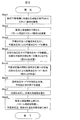
- FIG. 2 is a diagram showing an operation flowchart of the imprint apparatus Ip of this embodiment.
- FIG. 3 is a diagram illustrating a state of the imprint apparatus Ip at a representative position in the operation flow illustrated in FIG.
- FIG. 4 is a timing chart of the operation flow.
- the vertical axis indicates the positions of the transfer mechanism upper part 10 and the flat pressurizing body 21, and the operating states of the flat pressurizing chamber 25, the fluid pressurizing chamber 26, and the light source 22, and the horizontal axis indicates time t.
- Step 1 A stamper base material SB previously dripped around the photocurable resin P in the previous step on the fixing portion of the transfer mechanism lower portion 20 facing the pattern original plate 11 sucked and fixed to the suction plate 12 of the transfer mechanism upper portion 10. Is placed (state shown in FIG. 3A).
- FIG. 3A is the same as FIG.
- Step 2 As shown in the timing chart of FIG. 4 (hereinafter simply referred to as a chart), the transfer upper mechanism 10 having the suction plate 12 and the pattern original plate 11 is lowered, and the pattern original plate 11 is stamped through the photocurable resin P. Adhere to the substrate SB. At this time, the photocurable resin P is sandwiched between the pattern original plate 11 and the stamper base material SB and is thinly stretched, but is not a sufficiently uniform layer.
- Step 3 As shown in the chart of FIG. 4, with a slight delay, the compressed fluid is injected into the flat pressurizing chamber 25 from the flat fluid pipe 27 shown in FIG. 3B, the flat pressurizing body 21 is pushed up, and light curing is performed.
- the plane pressurization mode in which the functional resin P is plane-pressurized with the plane pressurization body 21 is started.
- Step 4 As shown in the chart of FIG. 4, when the predetermined pressurization pressure is reached, the predetermined pressurization pressure is maintained for a timer period until the layer of the photocurable resin P is spread to a predetermined uniform thickness. Then, the plane pressurization mode is continued (state shown in FIG. 3B).
- Step 5 As shown in the chart of FIG. 4, the compressed fluid in the flat pressurizing chamber 25 is sucked from the flat fluid pipe 27 while releasing the pressure while controlling the speed of the compressed fluid in the flat pressurization chamber 25.
- the fluid is pressurized into the fluid pressurizing chamber 26.
- the flat pressurizing body 21 descends, but the pressing force of the flat pressurizing body 21 applied to the stamper base material SB and the pressure of the compressed fluid injected from the pressurizing pipe 28 are interchanged without delay.
- the layer of the conductive resin P shifts to a fluid pressurizing mode in which the layer is pressurized only with the compressed fluid while maintaining a predetermined (sufficient) uniform thickness (state of FIG. 3C).
- Step 6 As shown in the chart of FIG. 4, when the pressurization to the stamper base material SB in the fluid pressurization mode is stabilized, the flat pressurizing chamber 25 is depressurized and the flat pressurizing body 21 is lowered.
- Step 7 As shown in the chart of FIG. 4, when the flat pressing body 21 reaches a predetermined position, the light source 22 is turned on for a certain period of time, and the photocurable resin P is exposed and cured. At this time, the flat pressure member 21 maintains a sufficient distance from the photocurable resin P so that the shadows do not affect the exposure even if there are minute scratches, dirt, or foreign matter on the surface. It is possible to cure the photocurable resin P with uniform energy intensity.
- Step 8 As shown in the chart of FIG. 4, the transfer mechanism upper part 10 supporting the suction plate 12 is raised, the pattern original 11 is peeled from the stamper base SB, and the flat pressurizing chamber 25 and the fluid pressurizing chamber 26 are moved. Return to the initial state. Thereafter, Step 1 to Step 8 are repeated.
- pressurization capable of smoothly switching from planar pressurization to fluid pressurization while maintaining pressurization to the stamper base material SB at a predetermined pressure.
- Mechanisms and pressure methods can be provided.
- it has both the advantages of the two known pressurizing methods and solves the respective disadvantages, and is provided with a transfer pattern layer having a uniform thickness with no flaw defects that are difficult to produce with the prior art.
- High quality stamper can be manufactured stably.
- FIG. 5 shows a configuration diagram of the second embodiment of the imprint apparatus Ip of the present invention.
- the differences from the first embodiment are the following two points. 5 having the same structure and the same function as those in FIG. 1 are denoted by the same reference numerals as those in FIG.
- the light source 22 is provided on the lower portion 20 of the transfer mechanism and UV light is irradiated from below the photocurable resin P, whereas in the second embodiment, the light source 22 is placed on the upper portion of the transfer mechanism.
- the UV light is irradiated from above the ten suction plates 12. Therefore, the suction plate is made of a member that transmits UV light, for example, glass.
- the flat pressure member 21 does not need to be glass.
- the flat pressure member is driven by the compressed fluid
- the air cylinder 37 is provided between the air drive base 36 and the flat pressure member 21. And driving the flat pressure member.
- the flat pressing body 21 is not necessarily a transparent glass body.
- the operation flow in the second embodiment is basically the same, the air cylinder 36 is monitored while monitoring the pressure of the fluid pressurizing chamber 26 in order to surely shift from the plane pressurizing mode to the fluid pressurizing mode. You may control the pressure by the plane pressurization body 21 by.
- the pressurization to the stamper base material SB can be smoothly switched from the plane pressurization to the fluid pressurization while maintaining the pressurization to the predetermined pressure.
- a pressure mechanism and a pressure method can be provided. As a result, it has both the advantages of the two known pressurizing methods and solves the respective disadvantages, and is provided with a transfer pattern layer having a uniform thickness with no flaw defects that are difficult to produce with the prior art. High quality stamper can be manufactured stably.
- the transfer side of the transfer object is the surface
- the pressure surface by the fluid pressurization body and the compressed fluid is used as the transfer object.
- the back side a pressurizing surface by a fluid pressurizing body or a compressed fluid may be provided on the back surface side of the stamper that is the pattern original plate.
- FIG. 6 shows a configuration diagram of the third embodiment of the imprint apparatus Ip of the present invention.
- 6A, 6B, and 6C correspond to FIGS. 3A, 3B, and 3C. 6 having the same structure and the same function as those in FIG. 3 are denoted by the same reference numerals as those in FIG. Differences from the second embodiment will be described with reference to FIG.
- the third embodiment is the same as the second embodiment in that the planar pressurizing body 29 is driven by the air cylinder 37, but the configuration of fluid pressurization is different from that of the second embodiment. Other configurations are basically the same as those of the second embodiment.
- the flat pressing body 29 has a plurality of grooves 38 having a predetermined height on the pressing surface, and a through hole 39 connected to the grooves.
- the fluid pressurizing unit includes the nozzle 40 having substantially the same height that can be inserted into the groove, a connecting pipe 41 provided in the through hole 39, and a fluid that supplies a compressed fluid to the connecting pipe 41. And a pressurizing pipe 28.
- FIG. 6B shows a state in which the transfer mechanism upper part 10 is lowered, is in close contact with the stamper base material SB, the flat pressure member 29 is pressed upward by the air cylinder 37, and the photocurable resin P is flatly pressed. Indicates. Depending on the size of the groove 38, the thickness uniformity of the transfer pattern layer may be lost. In that case, a compressed fluid is injected into each nozzle 40, and the same pressure as that of the flat pressure member 29 or a pressure that does not lose the uniformity is applied to the photocurable resin P having the grooves 38.
- FIG. 6 (c) is a diagram showing a state in which the plane pressurization mode is switched to the fluid pressurization mode using only the compressed fluid. Even if there are minute scratches, dirt, or foreign matters on the surface of the flat pressure member 29, the shadow is lowered to a position where the shadow does not affect the exposure. In the initial stage of the descent, the supply amount of the compressed fluid supplied to each nozzle is increased so that the pressing force of the planar pressurizing body 29 applied to the stamper base material SB and the applied pressure of the injected compressed fluid are interchanged without delay.
- the transfer side of the transfer target is the surface
- the pressurizing surface by the fluid pressurizing body and the compressed fluid is used.
- it is on the back side of the transfer target, it may be provided on the back side of the stamper that is the pattern original. Also in the third embodiment having the configuration and operation flow described above, the same effects as those of the first and second embodiments can be obtained.
Landscapes
- Engineering & Computer Science (AREA)
- Chemical & Material Sciences (AREA)
- Nanotechnology (AREA)
- Physics & Mathematics (AREA)
- General Physics & Mathematics (AREA)
- Crystallography & Structural Chemistry (AREA)
- Mechanical Engineering (AREA)
- Manufacturing & Machinery (AREA)
- Condensed Matter Physics & Semiconductors (AREA)
- Mathematical Physics (AREA)
- Theoretical Computer Science (AREA)
- Shaping Of Tube Ends By Bending Or Straightening (AREA)
- Exposure Of Semiconductors, Excluding Electron Or Ion Beam Exposure (AREA)
Abstract
本発明は、スタンパの表面に有する凹凸形状を、被転写体にエネルギーを照射し、転写し、前記スタンパを前記被転写体から剥離するインプリント装置又はその転写方法であり、前記スタンパ又は前記被転写体の少なくとも一方の第1の裏面を、平面加圧体で加圧し、前記スタンパ又は前記被転写体の少なくとも一方の第2の裏面を流体で加圧し、前記加圧平面体による加圧と前記流体による加圧との加圧タイミングを制御して前記転写を行う。
Description
本発明は、表面に特に微細な凹凸を有するスタンパと被転写体を加圧し、前記被転写体表面に前記スタンパの凹凸形状を転写するインプリント装置およびインプリント転写方法に関する。
近年、微細なパターン形成を低コストで行うためのインプリント技術が提案されている。このインプリント技術は、形成しようとするパターンの凹凸に対応する凹凸(表面形状)が形成されたスタンパを、例えば所定の基板上に樹脂層を形成して得られる被転写体に型押しするものであり、微細パターンを被転写体の樹脂層に形成することができる。そして、このインプリント技術は、ハードディスク等の大容量記録媒体における記録ビットのパターンの形成や、半導体集積回路のパターンの形成への応用が検討されている。
ハードディスク等の記録媒体の製造工程におけるインプリント装置では、転写するパターン原版としてスタンパを必要とする。このスタンパの製造工程においては、電子ビーム加工装置などにより微細加工された上位のパターン原版を、スタンパ基材上の樹脂層に転写することでスタンパを製造する。この転写による製造方法は、熱インプリントもしくは光インプリントを使用して行われる。
このような従来のインプリント技術としては、スタンパを作成するにあたり、光学研磨された平面ガラスの押し当てによる平面加圧方式(特許文献1)と、圧縮されたクリーンエアの圧力による流体加圧方式(特許文献2)の、2種類の転写方法があった。
平面加圧方式の長所は、数100nmの平面度で研磨された平面を押し当てることにより、UV硬化樹脂の均一な塗布厚が得られることである。一方、パターン直近の光源側にゴミや汚れの付着、傷がある場合など、樹脂直近で紫外(UV)光を遮ることで硬化品質の均一性が損なわれることが短所である。
また、流体加圧方式の長所は、100nm以下までフィルタリングされたクリーンエアのみが樹脂近傍に存在するので非常に均一な硬化品質が得られることである。一方、樹脂を平面で押圧しないので、樹脂の塗布厚の均一性は、樹脂の自己流動性に頼るしかないことが短所である。
また、流体加圧方式の長所は、100nm以下までフィルタリングされたクリーンエアのみが樹脂近傍に存在するので非常に均一な硬化品質が得られることである。一方、樹脂を平面で押圧しないので、樹脂の塗布厚の均一性は、樹脂の自己流動性に頼るしかないことが短所である。
従って、本発明の目的は、ガラスにゴミや汚れの付着、傷がある場合においても、UV光による硬化品質の均一性を保ち、UV硬化樹脂の均一な塗布厚が得られるインプリント装置又はインプリント転写方法を提供することにある。
本発明は、上記目的を達成するために、少なくとも以下の特徴を有する。
本発明は、スタンパの表面に有する凹凸形状を、被転写体にエネルギーを照射し、前記転写体に転写し、その後、前記スタンパを前記被転写体から剥離するインプリント装置またはインプリント転写方法において、前記スタンパ又は前記被転写体の少なくとも一方の第1の裏面を、平面形状を有する平面加圧体で加圧し、その後、前記スタンパ又は前記被転写体の少なくとも一方の第2の裏面を流体で加圧し、前記加圧平面体による加圧と、前記流体による加圧との加圧タイミングを制御して前記転写を行うことを第1の特徴とする。
本発明は、スタンパの表面に有する凹凸形状を、被転写体にエネルギーを照射し、前記転写体に転写し、その後、前記スタンパを前記被転写体から剥離するインプリント装置またはインプリント転写方法において、前記スタンパ又は前記被転写体の少なくとも一方の第1の裏面を、平面形状を有する平面加圧体で加圧し、その後、前記スタンパ又は前記被転写体の少なくとも一方の第2の裏面を流体で加圧し、前記加圧平面体による加圧と、前記流体による加圧との加圧タイミングを制御して前記転写を行うことを第1の特徴とする。
また、前記第1の裏面と前記第2の裏面は同一の裏面であることを第2の特徴とする。
さらに、前記第1の裏面と前記第2の裏面は異なる裏面あることを第3の特徴とする。
また、前記制御は、前記加圧平面体による加圧か前記流体による加圧へ移行する際に前記加圧を所定の圧力に略維持するように行うことを第4の特徴とする。
さらに、前記エネルギーは熱または光であることを第5の特徴とする。
さらに、前記第1の裏面と前記第2の裏面は異なる裏面あることを第3の特徴とする。
また、前記制御は、前記加圧平面体による加圧か前記流体による加圧へ移行する際に前記加圧を所定の圧力に略維持するように行うことを第4の特徴とする。
さらに、前記エネルギーは熱または光であることを第5の特徴とする。
本発明によれば、ガラスにゴミや汚れの付着、傷がある場合においても、UV光による硬化品質の均一性を保ち、UV硬化樹脂の均一な塗布厚が得られるインプリント装置又はインプリント転写方法を提供できる。
以下、図面を用いて本発明の実施形態を説明する。図1は本発明のインプリント装置Ipの第1の実施形態の構成図を示す。
インプリント装置Ipは、大別して、スタンパの成形材料である光硬化性樹脂Pより上部に構成要素を持つ転写機構上部10と、光硬化性樹脂Pより下部に構成要素を持つ転写機構下部30とを有する。転写機構上部10は、スタンパであるパターン原版11と、パターン原版11を平面に保ちかつ吸着保持するための吸着板12とを有する。吸着板12は、図面上で上下方向に動作するアクチュエーター(図示せず)に保持されている。
インプリント装置Ipは、大別して、スタンパの成形材料である光硬化性樹脂Pより上部に構成要素を持つ転写機構上部10と、光硬化性樹脂Pより下部に構成要素を持つ転写機構下部30とを有する。転写機構上部10は、スタンパであるパターン原版11と、パターン原版11を平面に保ちかつ吸着保持するための吸着板12とを有する。吸着板12は、図面上で上下方向に動作するアクチュエーター(図示せず)に保持されている。
一方、転写機構下部20は、光硬化性樹脂Pと共に被転写体を構成するスタンパ基材SBをパターン原版11に型押しするガラス製の平面加圧体21と、UV光を光硬化性樹脂Pに照射する光源22と、UV光を透過する光学窓23、平面加圧体21及び光学窓23並びにハウジング24とで形成される平面加圧室25と、ハウジング24に固定保持され平面加圧室25に圧縮流体を注入する平面加圧用配管27と、スタンパ基材SB及び平面加圧体21並びにハウジング24とで形成される流体加圧室26と、ハウジング24に固定保持され流体加圧室26に圧縮流体を注入する流体加圧用配管28と、平面加圧室25及び流体加圧室26を、それぞれの境界領域をシールするOリング31~35とを有する。Oリング31、32及び33が平面加圧室25を、Oリング34、35が流体加圧室26をシールしている。
第1の実施形態では、被転写体の被転写側を表面とすれば、流体加圧体及び圧縮流体による加圧面を被転写体の裏面側としている。
尚、上記実施形態は、転写機構上部10と、転写機構下部20がお互いに上下逆に構成されてもその機能や特徴が変化しない。また、パターン原版であるスタンパのパターンを有する側を表面とすれば、流体加圧体及び圧縮流体による加圧面をスタンパ側の裏面側としてもよい。そこで、製造装置全体の設計として合理的な姿勢を選択することが可能である。
尚、上記実施形態は、転写機構上部10と、転写機構下部20がお互いに上下逆に構成されてもその機能や特徴が変化しない。また、パターン原版であるスタンパのパターンを有する側を表面とすれば、流体加圧体及び圧縮流体による加圧面をスタンパ側の裏面側としてもよい。そこで、製造装置全体の設計として合理的な姿勢を選択することが可能である。
次に、第1の実施形態のインプリント装置Ipの動作を図2、図3及び図4用いて説明する。図2は本実施形態のインプリント装置Ipの動作フローチャートを示す図である。図3は、図2に示す動作フローのうち、代表的な位置におけるインプリント装置Ipの状態を示す図である。図4は前記動作フローのタイミングチャートを示す図である。図4において、縦軸は、転写機構上部10及び平面加圧体21の位置と、平面加圧室25、流体加圧室26及び光源22の動作状態を示し、横軸は時間tを示す。
以下、本実施形態のインプリント装置Ipの動作を図2の動作フローチャートを主体に、図3及び図4を参照しながら説明する。
Step1:転写機構上部10の吸着板12に吸着固定されたパターン原版11に対向させた転写機構下部20の固定部に、前工程で予め光硬化性樹脂Pを中心に滴下されたスタンパ基材SBを載置する(図3(a)の状態)。なお、図3(a)は図1と同じで図である。
Step1:転写機構上部10の吸着板12に吸着固定されたパターン原版11に対向させた転写機構下部20の固定部に、前工程で予め光硬化性樹脂Pを中心に滴下されたスタンパ基材SBを載置する(図3(a)の状態)。なお、図3(a)は図1と同じで図である。
Step2:図4のタイミングチャート(以下、単にチャートという)に示すように、吸着板12とパターン原版11とを有する転写上部機構10を降下させ、パターン原版11を光硬化性樹脂Pを介してスタンパ基材SBに密着させる。このとき光硬化性樹脂Pは、パターン原版11とスタンパ基材SBに挟まれ、薄く押し延ばされた状態であるが、充分に均一な厚さの層にはなっていない。
Step3:図4のチャートに示すように、やや遅れて、図3(b)に示す平面流体用配管27から圧縮流体を平面加圧室25に注入し、平面加圧体21を押し上げ、光硬化性樹脂Pを平面加圧体21で平面加圧する平面加圧モードを開始する。
Step4:図4のチャートに示すように、所定の加圧圧力に達したら、光硬化性樹脂Pの層が所定の均一な厚さに押し広げられるまで、所定の加圧圧力をタイマー期間維持し、平面加圧モードを継続する(図3(b)の状態)。
Step4:図4のチャートに示すように、所定の加圧圧力に達したら、光硬化性樹脂Pの層が所定の均一な厚さに押し広げられるまで、所定の加圧圧力をタイマー期間維持し、平面加圧モードを継続する(図3(b)の状態)。
Step5:図4のチャートに示すように、平面加圧室25の圧縮流体を速度制御しながら平面流体用配管27から吸引し圧力を開放するのとほぼ同時に、流体加圧用配管28から圧縮流体を流体加圧室26に注入する。その結果、平面加圧体21は降下するが、スタンパ基材SBにかかる平面加圧体21の押付け力と加圧用配管28より注入された圧縮流体の加圧力が遅滞無く入れ替わることで、光硬化性樹脂Pの層は、所定の(充分に)均一な厚さを保ったまま、圧縮流体のみで加圧された流体加圧モードに移行する(図3(c)の状態)。
Step6:図4のチャートに示すように、流体加圧モードでのスタンパ基材SBへの加圧が安定したら、平面加圧室25を減圧し、平面加圧体21の降下を促進する。
Step7:図4のチャートに示すように、平面加圧体21が所定の位置まできたら、光源22を一定時間点灯し、光硬化性樹脂Pを露光硬化させる。このとき平面加圧体21は、その表面に微小な傷、汚れ、異物があっても、それらの影が露光に影響を与えないに充分な光硬化性樹脂Pとの距離を保っているので、光硬化性樹脂Pを均一なエネルギー強度で硬化させることが可能である。
Step7:図4のチャートに示すように、平面加圧体21が所定の位置まできたら、光源22を一定時間点灯し、光硬化性樹脂Pを露光硬化させる。このとき平面加圧体21は、その表面に微小な傷、汚れ、異物があっても、それらの影が露光に影響を与えないに充分な光硬化性樹脂Pとの距離を保っているので、光硬化性樹脂Pを均一なエネルギー強度で硬化させることが可能である。
Step8:図4のチャートに示すように、吸着板12を支えている転写機構上部10を上昇させ、パターン原版11をスタンパ基材SBから剥離し、平面加圧室25及び流体加圧室26を初期状態に戻す。
以後、Step1からStep8を繰り返す。
以後、Step1からStep8を繰り返す。
以上説明した、本発明の第1の実施形態によれば、スタンパ基材SBへの加圧を所定の圧力に維持しながら、平面加圧から流体加圧へのスムーズな切り替えが可能な加圧機構及び加圧方法を提供できる。その結果、前記2種類の公知の加圧方法の長所を両立し、またそれぞれの短所を解決した、従来技術では作成困難であった 欠陥が無く、かつ均一な厚さの転写パターン層を備えた、良質なスタンパを安定して製造できる。
図5は本発明のインプリント装置Ipの第2の実施形態の構成図を示す。第1の実施形態と異なる点は次の2点である。図5において、図1と同一構造、同一機能を有するものは図1と同一符号を用いている。
第1に、第1の実施形態では光源22を転写機構下部20に設け光硬化性樹脂Pの下からUV光を照射していたのに対し、第2の実施形態では光源22を転写機構上部10の吸着板12の上からからUV光を照射する。そのために、吸着板はUV光を透過する部材、例えばガラスで構成する。一方、平面加圧体21はガラスである必要はない。
第2に、第1の実施形態では平面加圧体を圧縮流体で駆動していたのに対し、第2の実施形態では、エア駆動ベース36と平面加圧体21との間にエアシリンダ37を設け、平面加圧体を駆動する。この場合、必ずしも平面加圧体21は透明なガラス体でなくともよい。
第2の実施形態における動作フローは基本的に同じであるが、平面加圧モードから流体加圧モードに移行を確実に行うには、流体加圧室26の圧力を監視しながら、エアシリンダ36による平面加圧体21による圧力を制御してもよい。
第1に、第1の実施形態では光源22を転写機構下部20に設け光硬化性樹脂Pの下からUV光を照射していたのに対し、第2の実施形態では光源22を転写機構上部10の吸着板12の上からからUV光を照射する。そのために、吸着板はUV光を透過する部材、例えばガラスで構成する。一方、平面加圧体21はガラスである必要はない。
第2に、第1の実施形態では平面加圧体を圧縮流体で駆動していたのに対し、第2の実施形態では、エア駆動ベース36と平面加圧体21との間にエアシリンダ37を設け、平面加圧体を駆動する。この場合、必ずしも平面加圧体21は透明なガラス体でなくともよい。
第2の実施形態における動作フローは基本的に同じであるが、平面加圧モードから流体加圧モードに移行を確実に行うには、流体加圧室26の圧力を監視しながら、エアシリンダ36による平面加圧体21による圧力を制御してもよい。
以上説明した、本発明の第2の実施形態によれば、スタンパ基材SBへの加圧を所定内の圧力に維持しながら、平面加圧から流体加圧へのスムーズな切り替えが可能な加圧機構及び加圧方法を提供できる。その結果、前記2種類の公知の加圧方法の長所を両立し、またそれぞれの短所を解決した、従来技術では作成困難であった 欠陥が無く、かつ均一な厚さの転写パターン層を備えた、良質なスタンパを安定して製造できる。
以上説明した、本発明の第2の実施形態では、第1の実施形態と同様に、被転写体の被転写側を表面とすれば、流体加圧体及び圧縮流体による加圧面を被転写体の裏面側としている。しかしながら、流体加圧体または圧縮流体による加圧面を、パターン原版であるスタンパの裏面側に設けてもよい。
図6は本発明のインプリント装置Ipの第3の実施形態の構成図を示す。図6の(a)、(b)、(c)は、図3の(a)、(b)、(c)に対応する図である。図6において、図3と同一構造、同一機能を有するものは図3と同一符号を用いている。
図6(a)を用いて第2の実施形態との構成上に異なる点を説明する。第3の実施形態は、第2の実施形態とエアシリンダ37で平面加圧体29を駆動する点は同じであるが、流体加圧の構成が第2の実施形態とは異なる。その他の構成は、基本的には第2の実施形態と同じである。平面加圧体29は、その加圧面に所定の高さを持つ複数の溝38と、前記溝に連結された貫通孔39を有する。一方、流体加圧部は、前記溝に挿入可能な前記所定に略同じ高さを有するノズル40と、前記貫通孔39に設けられた連結管41と、連結管41に圧縮流体を供給する流体加圧用配管28とを有する。
図6(a)を用いて第2の実施形態との構成上に異なる点を説明する。第3の実施形態は、第2の実施形態とエアシリンダ37で平面加圧体29を駆動する点は同じであるが、流体加圧の構成が第2の実施形態とは異なる。その他の構成は、基本的には第2の実施形態と同じである。平面加圧体29は、その加圧面に所定の高さを持つ複数の溝38と、前記溝に連結された貫通孔39を有する。一方、流体加圧部は、前記溝に挿入可能な前記所定に略同じ高さを有するノズル40と、前記貫通孔39に設けられた連結管41と、連結管41に圧縮流体を供給する流体加圧用配管28とを有する。
このような構成によって、第3の実施形態は下記の特徴的な動作フローを有する。
図6(b)は、転写機構上部10が下降し、スタンパ基材SBと密着し、平面加圧体29をエアシリンダ37により上方に加圧し、光硬化性樹脂Pを平面加圧している状態を示す。溝38の大きさによっては転写パターン層の厚さ均一性が失われる場合がある。その場合は、各ノズル40に圧縮流体を注入し、平面加圧体29と同じ又は均一性が失われない程度の圧力を溝38のある光硬化性樹脂Pにかける。
図6(b)は、転写機構上部10が下降し、スタンパ基材SBと密着し、平面加圧体29をエアシリンダ37により上方に加圧し、光硬化性樹脂Pを平面加圧している状態を示す。溝38の大きさによっては転写パターン層の厚さ均一性が失われる場合がある。その場合は、各ノズル40に圧縮流体を注入し、平面加圧体29と同じ又は均一性が失われない程度の圧力を溝38のある光硬化性樹脂Pにかける。
図6(c)は、平面加圧モードから圧縮流体のみによる流体加圧モードへの切り替える様子を示す図である。平面加圧体29は、エアシリンダ37によって、その表面に微小な傷、汚れ、異物があっても、それらの影が露光に影響を与えない位置まで降下する。その降下の初期において、スタンパ基材SBにかかる平面加圧体29の押付け力と注入された圧縮流体の加圧力が遅滞無く入れ替わるように各ノズルに供給する圧縮流体の供給量を多くする。
以上説明した、本発明の第3の実施形態では、第1、第2の実施形態と同様に、被転写体の被転写側を表面とすれば、流体加圧体及び圧縮流体による加圧面を被転写体の裏面側としているが、パターン原版であるスタンパの裏面側に設けてもよい。
上記に説明した構成及び動作フローを有する第3の実施形態においても、第1と第2の実施形態と同様な効果を奏することができる。
上記に説明した構成及び動作フローを有する第3の実施形態においても、第1と第2の実施形態と同様な効果を奏することができる。
10:転写機構上部 11:パターン原版 12:吸着板
20:転写機構下部 21:第1、第2の実施態における平面加圧体
22:光源 23:光学窓 24:ハウジング
25:ハウジング 26:流体加圧室 27:平面加圧用配管
28:流体加圧用配管 29:第3の実施態における平面加圧体
31~35:Oリング 36:エア駆動ベース 37:エアシリンダ
38:平面加圧体の表面の溝 39:平面加圧体の貫通孔 40:ノズル
41:連結管 Ip:インプリント装置 P:光硬化性樹脂
SB:スタンパ基材
20:転写機構下部 21:第1、第2の実施態における平面加圧体
22:光源 23:光学窓 24:ハウジング
25:ハウジング 26:流体加圧室 27:平面加圧用配管
28:流体加圧用配管 29:第3の実施態における平面加圧体
31~35:Oリング 36:エア駆動ベース 37:エアシリンダ
38:平面加圧体の表面の溝 39:平面加圧体の貫通孔 40:ノズル
41:連結管 Ip:インプリント装置 P:光硬化性樹脂
SB:スタンパ基材
Claims (14)
- 表面に凹凸形状を有するスタンパと、前記凹凸形状が表面に転写される被転写体と、前記被転写体にエネルギーを照射するエネルギー源とを有し、前記スタンパを前記被転写体から剥離するインプリント装置において、
前記スタンパ又は前記被転写体の少なくとも一方の第1の裏面を平面形状を有する平面加圧体で加圧する平面加圧手段と、前記スタンパ又は前記被転写体の少なくとも一方の第2の裏面を流体で加圧する流体加圧手段と、前記平面加圧手段と前記流体加圧手段との加圧タイミングを制御する制御手段を有することを特徴とするインプリント装置。 - 前記第1の裏面と前記第2の裏面は同一の裏面であることを特徴とする請求項1に記載のインプリント装置。
- 前記同一の裏面は前記スタンパの裏面であることを特徴とする請求項2に記載のインプリント装置。
- 前記同一の裏面は前記被転写体の裏面であることを特徴とする請求項2に記載のインプリント装置。
- 前記第1の裏面と前記第2の裏面は異なる裏面であることを特徴とする請求項1に記載のインプリント装置。
- 前記第1の裏面は前記スタンパの裏面であり、前記第2の裏面は前記被転写体の裏面であることを特徴とする請求項5に記載のインプリント装置。
- 前記第1の裏面は前記被転写体の裏面であり、前記第2の裏面はスタンパの裏面であるあることを特徴とする請求項5に記載のインプリント装置。
- 前記制御手段は、前記平面加圧手段から前記流体加圧手段へ移行する際に前記加圧を所定の圧力に略維持するように制御することを特徴とする請求項1に記載のインプリント装置。
- 前記エネルギー源は熱源または光源であることを特徴とする請求項1に記載のインプリント装置。
- スタンパの表面に有する凹凸形状を、被転写体にエネルギーを照射し、前記転写体に転写し、その後、前記スタンパを前記被転写体から剥離するインプリント転写方法において、
前記スタンパ又は前記被転写体の少なくとも一方の第1の裏面を、平面形状を有する平面加圧体で加圧し、その後、前記スタンパ又は前記被転写体の少なくとも一方の第2の裏面を流体で加圧し、前記加圧平面体による加圧と、前記流体による加圧との加圧タイミングを制御して前記転写を行うことを特徴とするインプリント転写方法。 - 前記第1の裏面と前記第2の裏面は同一の裏面であることを特徴とする請求項10に記載のインプリント転写方法。
- 前記第1の裏面と前記第2の裏面は異なる裏面であることを特徴とする請求項10に記載のインプリント転写方法。
- 前記制御は、前記加圧平面体による加圧か前記流体による加圧へ移行する際に前記加圧を所定の圧力に略維持するように行うことを特徴とする請求項10に記載のインプリント転写方法。
- 前記エネルギーは熱または光であることを特徴とする請求項10に記載のインプリント転写方法。
Applications Claiming Priority (2)
| Application Number | Priority Date | Filing Date | Title |
|---|---|---|---|
| JP2010-168314 | 2010-07-27 | ||
| JP2010168314A JP5677667B2 (ja) | 2010-07-27 | 2010-07-27 | インプリント装置及びインプリント転写方法 |
Publications (1)
| Publication Number | Publication Date |
|---|---|
| WO2012014869A1 true WO2012014869A1 (ja) | 2012-02-02 |
Family
ID=45525922
Family Applications (1)
| Application Number | Title | Priority Date | Filing Date |
|---|---|---|---|
| PCT/JP2011/066918 Ceased WO2012014869A1 (ja) | 2010-07-27 | 2011-07-26 | インプリント装置及びインプリント転写方法 |
Country Status (3)
| Country | Link |
|---|---|
| US (1) | US8827686B2 (ja) |
| JP (1) | JP5677667B2 (ja) |
| WO (1) | WO2012014869A1 (ja) |
Cited By (1)
| Publication number | Priority date | Publication date | Assignee | Title |
|---|---|---|---|---|
| TWI764926B (zh) * | 2016-09-27 | 2022-05-21 | 美商伊路米納有限公司 | 產生壓印無殘餘基板表面之方法和流量槽 |
Families Citing this family (3)
| Publication number | Priority date | Publication date | Assignee | Title |
|---|---|---|---|---|
| JP6031655B2 (ja) * | 2011-09-06 | 2016-11-24 | Scivax株式会社 | 剛体ステージを備えた流体圧インプリント装置 |
| JP5935453B2 (ja) * | 2012-03-30 | 2016-06-15 | 大日本印刷株式会社 | 基板の製造方法、および、ナノインプリントリソグラフィ用テンプレートの製造方法 |
| US11181819B2 (en) * | 2019-05-31 | 2021-11-23 | Canon Kabushiki Kaisha | Frame curing method for extrusion control |
Citations (4)
| Publication number | Priority date | Publication date | Assignee | Title |
|---|---|---|---|---|
| JP2003516644A (ja) * | 1999-12-10 | 2003-05-13 | オブドゥカト アクティエボラーグ | 構造物の製造に関する装置および方法 |
| JP2007083626A (ja) * | 2005-09-22 | 2007-04-05 | Ricoh Co Ltd | 微細構造転写装置 |
| JP2007287942A (ja) * | 2006-04-18 | 2007-11-01 | Hitachi High-Technologies Corp | 微細構造パターンの転写方法及び転写装置 |
| JP2010506427A (ja) * | 2006-10-10 | 2010-02-25 | ヒューレット−パッカード デベロップメント カンパニー エル.ピー. | 液圧によって促進されるコンタクトリソグラフィ装置、システム及び方法 |
Family Cites Families (5)
| Publication number | Priority date | Publication date | Assignee | Title |
|---|---|---|---|---|
| FR2694906B1 (fr) * | 1992-08-20 | 1994-09-23 | Acb | Presse pour le formage d'une pièce en matériau composite comportant des renforts fibreux dans une matrice en polymère. |
| IT1294944B1 (it) * | 1997-08-01 | 1999-04-23 | Sacmi | Metodo per formare piastrelle ceramiche di grandi dimensioni mediante stampi parzialmente isostatici, e dispositivo per attuare il metodo. |
| JP4596981B2 (ja) | 2005-05-24 | 2010-12-15 | 株式会社日立ハイテクノロジーズ | インプリント装置、及び微細構造転写方法 |
| JP5155814B2 (ja) | 2008-10-21 | 2013-03-06 | 株式会社日立ハイテクノロジーズ | インプリント装置 |
| US8747092B2 (en) * | 2010-01-22 | 2014-06-10 | Nanonex Corporation | Fast nanoimprinting apparatus using deformale mold |
-
2010
- 2010-07-27 JP JP2010168314A patent/JP5677667B2/ja not_active Expired - Fee Related
-
2011
- 2011-07-25 US US13/189,759 patent/US8827686B2/en not_active Expired - Fee Related
- 2011-07-26 WO PCT/JP2011/066918 patent/WO2012014869A1/ja not_active Ceased
Patent Citations (4)
| Publication number | Priority date | Publication date | Assignee | Title |
|---|---|---|---|---|
| JP2003516644A (ja) * | 1999-12-10 | 2003-05-13 | オブドゥカト アクティエボラーグ | 構造物の製造に関する装置および方法 |
| JP2007083626A (ja) * | 2005-09-22 | 2007-04-05 | Ricoh Co Ltd | 微細構造転写装置 |
| JP2007287942A (ja) * | 2006-04-18 | 2007-11-01 | Hitachi High-Technologies Corp | 微細構造パターンの転写方法及び転写装置 |
| JP2010506427A (ja) * | 2006-10-10 | 2010-02-25 | ヒューレット−パッカード デベロップメント カンパニー エル.ピー. | 液圧によって促進されるコンタクトリソグラフィ装置、システム及び方法 |
Cited By (2)
| Publication number | Priority date | Publication date | Assignee | Title |
|---|---|---|---|---|
| TWI764926B (zh) * | 2016-09-27 | 2022-05-21 | 美商伊路米納有限公司 | 產生壓印無殘餘基板表面之方法和流量槽 |
| US11878299B2 (en) | 2016-09-27 | 2024-01-23 | Illumina, Inc. | Imprinted substrates |
Also Published As
| Publication number | Publication date |
|---|---|
| US8827686B2 (en) | 2014-09-09 |
| JP5677667B2 (ja) | 2015-02-25 |
| JP2012028685A (ja) | 2012-02-09 |
| US20120025419A1 (en) | 2012-02-02 |
Similar Documents
| Publication | Publication Date | Title |
|---|---|---|
| JP5411557B2 (ja) | 微細構造転写装置 | |
| TWI532601B (zh) | 在3d玻璃物件上網版印刷之方法 | |
| JP5478854B2 (ja) | システム | |
| TWI573685B (zh) | 奈米壓印方法及使用其的奈米壓印裝置 | |
| JP5232077B2 (ja) | 微細構造転写装置 | |
| JP2010036514A (ja) | ナノインプリント用スタンパ及び該スタンパを使用する微細構造転写装置 | |
| WO2012063948A1 (ja) | 金型の微細パターン面清掃方法とそれを用いたインプリント装置 | |
| JP2011150780A (ja) | 両面インプリント装置 | |
| JP5454160B2 (ja) | インプリント装置及びインプリント方法 | |
| US20170203471A1 (en) | Imprint template and method for producing the same | |
| JP5677667B2 (ja) | インプリント装置及びインプリント転写方法 | |
| JP5155814B2 (ja) | インプリント装置 | |
| JP2008155522A (ja) | インプリント方法およびその装置 | |
| JP2011151093A (ja) | インプリント装置及び物品の製造方法 | |
| JP2008200997A (ja) | ナノインプリント用金型の製造方法 | |
| TWI654060B (zh) | Imprinting device, imprinting method and article manufacturing method | |
| JPWO2007116469A1 (ja) | パターン転写方法およびパターン転写装置 | |
| JP5465474B2 (ja) | インプリント装置およびインプリント方法 | |
| JP2014069339A (ja) | スタンパ、スタンパ製造装置及びその製造方法並びに微細構造転写方法 | |
| KR101813896B1 (ko) | 임프린트 장치 | |
| JP6699146B2 (ja) | インプリント方法 | |
| JP2007324504A (ja) | 転写印刷方法、転写印刷装置およびそれを用いて製造した転写印刷製品 | |
| JP7721736B1 (ja) | 平坦化装置、平坦化方法、および物品の製造方法 | |
| JP2012099197A (ja) | 光インプリント方法 | |
| JP2007287942A (ja) | 微細構造パターンの転写方法及び転写装置 |
Legal Events
| Date | Code | Title | Description |
|---|---|---|---|
| 121 | Ep: the epo has been informed by wipo that ep was designated in this application |
Ref document number: 11812458 Country of ref document: EP Kind code of ref document: A1 |
|
| NENP | Non-entry into the national phase |
Ref country code: DE |
|
| 122 | Ep: pct application non-entry in european phase |
Ref document number: 11812458 Country of ref document: EP Kind code of ref document: A1 |