WO2012014863A1 - 車両用冷却水リザーブタンクの支持構造 - Google Patents
車両用冷却水リザーブタンクの支持構造 Download PDFInfo
- Publication number
- WO2012014863A1 WO2012014863A1 PCT/JP2011/066901 JP2011066901W WO2012014863A1 WO 2012014863 A1 WO2012014863 A1 WO 2012014863A1 JP 2011066901 W JP2011066901 W JP 2011066901W WO 2012014863 A1 WO2012014863 A1 WO 2012014863A1
- Authority
- WO
- WIPO (PCT)
- Prior art keywords
- reserve tank
- bracket
- vehicle
- cooling water
- engine
- Prior art date
- Legal status (The legal status is an assumption and is not a legal conclusion. Google has not performed a legal analysis and makes no representation as to the accuracy of the status listed.)
- Ceased
Links
Images



Classifications
-
- B—PERFORMING OPERATIONS; TRANSPORTING
- B60—VEHICLES IN GENERAL
- B60K—ARRANGEMENT OR MOUNTING OF PROPULSION UNITS OR OF TRANSMISSIONS IN VEHICLES; ARRANGEMENT OR MOUNTING OF PLURAL DIVERSE PRIME-MOVERS IN VEHICLES; AUXILIARY DRIVES FOR VEHICLES; INSTRUMENTATION OR DASHBOARDS FOR VEHICLES; ARRANGEMENTS IN CONNECTION WITH COOLING, AIR INTAKE, GAS EXHAUST OR FUEL SUPPLY OF PROPULSION UNITS IN VEHICLES
- B60K11/00—Arrangement in connection with cooling of propulsion units
- B60K11/02—Arrangement in connection with cooling of propulsion units with liquid cooling
-
- B—PERFORMING OPERATIONS; TRANSPORTING
- B60—VEHICLES IN GENERAL
- B60K—ARRANGEMENT OR MOUNTING OF PROPULSION UNITS OR OF TRANSMISSIONS IN VEHICLES; ARRANGEMENT OR MOUNTING OF PLURAL DIVERSE PRIME-MOVERS IN VEHICLES; AUXILIARY DRIVES FOR VEHICLES; INSTRUMENTATION OR DASHBOARDS FOR VEHICLES; ARRANGEMENTS IN CONNECTION WITH COOLING, AIR INTAKE, GAS EXHAUST OR FUEL SUPPLY OF PROPULSION UNITS IN VEHICLES
- B60K5/00—Arrangement or mounting of internal-combustion or jet-propulsion units
- B60K5/12—Arrangement of engine supports
- B60K5/1208—Resilient supports
-
- F—MECHANICAL ENGINEERING; LIGHTING; HEATING; WEAPONS; BLASTING
- F02—COMBUSTION ENGINES; HOT-GAS OR COMBUSTION-PRODUCT ENGINE PLANTS
- F02B—INTERNAL-COMBUSTION PISTON ENGINES; COMBUSTION ENGINES IN GENERAL
- F02B77/00—Component parts, details or accessories, not otherwise provided for
- F02B77/11—Thermal or acoustic insulation
- F02B77/13—Acoustic insulation
-
- B—PERFORMING OPERATIONS; TRANSPORTING
- B60—VEHICLES IN GENERAL
- B60K—ARRANGEMENT OR MOUNTING OF PROPULSION UNITS OR OF TRANSMISSIONS IN VEHICLES; ARRANGEMENT OR MOUNTING OF PLURAL DIVERSE PRIME-MOVERS IN VEHICLES; AUXILIARY DRIVES FOR VEHICLES; INSTRUMENTATION OR DASHBOARDS FOR VEHICLES; ARRANGEMENTS IN CONNECTION WITH COOLING, AIR INTAKE, GAS EXHAUST OR FUEL SUPPLY OF PROPULSION UNITS IN VEHICLES
- B60K5/00—Arrangement or mounting of internal-combustion or jet-propulsion units
- B60K5/12—Arrangement of engine supports
- B60K5/1208—Resilient supports
- B60K5/1216—Resilient supports characterised by the location of the supports relative to the motor or to each other
-
- F—MECHANICAL ENGINEERING; LIGHTING; HEATING; WEAPONS; BLASTING
- F01—MACHINES OR ENGINES IN GENERAL; ENGINE PLANTS IN GENERAL; STEAM ENGINES
- F01P—COOLING OF MACHINES OR ENGINES IN GENERAL; COOLING OF INTERNAL-COMBUSTION ENGINES
- F01P11/00—Component parts, details, or accessories not provided for in, or of interest apart from, groups F01P1/00 - F01P9/00
- F01P11/02—Liquid-coolant filling, overflow, venting, or draining devices
Definitions
- the present invention relates to a support structure for a cooling water reserve tank for a vehicle, and in particular, a vehicle that reduces idling vibration transmitted from a power train to a vehicle body using a cooling water reserve tank and a reserve tank bracket for storing engine cooling water.
- the present invention relates to a support structure for a cooling water reserve tank.
- a power train composed of an engine and a transmission arranged in an engine room is elastically supported on the vehicle body by a mounting device to suppress vibration transmitted to the vehicle body.
- the mounting device includes a power train side mounting bracket that is attached to the power train, a vehicle body side mounting bracket that is attached to a side member constituting the vehicle body, and a bush mount that elastically connects the power train side mounting bracket and the vehicle body side mounting bracket. It consists of.
- a vehicle has engine accessories in the engine room.
- a vehicle has a battery for supplying electric power to an engine and an auxiliary machine in an engine room, and a reserve tank for cooling water for compensating for loss of cooling water due to securing of an expansion space for cooling water accompanying a temperature rise and evaporation. Is arranged.
- a battery support structure there is a structure in which a battery tray on which a battery is placed is attached to a vehicle body side mounting bracket of a mounting device via a buffer (for example, Patent Document 1). Further, as a support structure for the coolant reserve tank, there is a structure in which a reserve tank bracket to which a reserve tank is attached is attached to a vehicle body side mount bracket of the mount device (for example, Patent Document 2).
- Patent Document 1 describes a configuration in which vibration generated in the vehicle body during idling of the engine is reduced by resonance of a vibration system configured by a battery, a battery tray, and a buffer.
- a vibration system configured by a battery, a battery tray, and a buffer.
- the weight of the battery is described. Therefore, the resonance frequency must be adjusted only by the shape of the buffer.
- Patent Document 2 describes a configuration in which a cooling water reserve tank is attached to a vehicle body side mounting bracket with a reserve tank bracket.
- the cooling water reserve tank is disposed so as not to interfere with the vehicle body side mounting bracket.
- it was not intended to reduce powertrain vibration.
- the present invention is a vehicle coolant reservoir tank that can reduce the vibration transmitted from the power train to the vehicle body by configuring a dynamic damper with existing components and can easily adjust the resonance frequency of the dynamic damper.
- the purpose is to realize a support structure.
- the present invention provides a vehicle reserve tank support structure in which a powertrain having an engine is supported on a vehicle body by a mount bracket, and a coolant reserve tank is attached to the mount bracket via a reserve tank bracket.
- a dynamic damper is constructed with the cooling water stored therein as a weight and the reserve tank bracket as an elastic body, and the resonance frequency of the dynamic damper is substantially matched to the frequency of vibration generated during idling operation of the engine. It is characterized by that.
- the cooling water reserve tank and the cooling water stored therein are weights of weight m.
- the resonance frequency f 1 / 2 ⁇ k / m of the dynamic damper formed by the weight and the elastic body is substantially matched with the frequency of vibration generated by combustion during idling operation of the engine.
- the vehicle cooling water reserve tank support structure comprises a dynamic damper that uses the cooling water reserve tank and the cooling water as weights, and the reserve tank bracket as an elastic body. Therefore, the idling vibration of the engine transmitted to the vehicle body by the dynamic damper. Can be reduced.
- the cooling water reserve tank support structure for a vehicle uses the cooling water reserve tank and the cooling water stored therein as a weight
- the weight of the cooling water reserve tank can be changed by changing the shape of the cooling water reserve tank or the cooling water amount.
- the position of the weight and the center of gravity can be freely adjusted, and the degree of freedom in setting the shape of the reserve tank bracket as an elastic body can be improved.
- a dynamic damper can be configured with existing components to reduce idling vibration transmitted from the powertrain to the vehicle body and to easily adjust the resonance frequency of the dynamic damper. Can do.
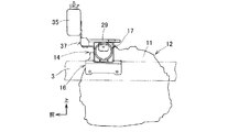
- FIG. 1 is a side view of a support structure for a vehicle coolant reserve tank according to an embodiment of the present invention.
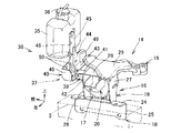
- FIG. 2 is a perspective view of a support structure for a vehicle coolant reserve tank according to an embodiment of the present invention.
- FIG. 3 is a perspective view of the reserve tank bracket in the above embodiment.
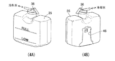
- 4A is a front perspective view of the cooling water reserve tank
- FIG. 4B is a rear perspective view of the cooling water reserve tank.
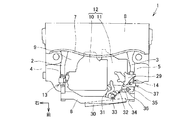
- FIG. 5 is a plan view in the engine room of the vehicle.
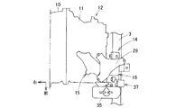
- FIG. 6 is an enlarged plan view of a mounting device portion of the vehicle power plant.
- FIG. 7 is an enlarged front view of the mounting device portion of the power plant.
- FIG. 8 is an enlarged side view of the mounting device portion of the power plant.
- the present invention provides a powertrain by making the resonance frequency of a dynamic damper, which uses a cooling water reserve tank and cooling water as a weight, and a reserve tank bracket as an elastic body, substantially matches the frequency of vibration generated during idling operation of the engine.
- the vibration transmitted from the vehicle to the vehicle body is reduced, and the resonance frequency of the dynamic damper can be easily adjusted.
- reference numeral 1 indicates a vehicle such as an automobile, for example.
- the vehicle 1 has a horizontally installed engine 10 and a power train 12 having a transmission 11 connected to the left side of the engine 10 arranged in an engine room 9. Yes.
- a pair of left and right side frames 2 and 3 and a pair of left and right side panels 4 and 5 are disposed on the left and right side portions of the power train 12.
- a cross member 6 is disposed on the front portion, a dash panel 7 and a floor panel 8 are disposed on the rear portion.
- An engine 10, a transmission 11, and a power train 12 are disposed in the engine room 9.
- the power train 12 supports the engine 10 on the right side frame 2 by the right mounting device 13, supports the transmission 11 on the left side frame 3 by the left mounting device 14, and further transmits the transmission by the rear mounting device. 11 is supported by the rear lower cross member. Since the left mounting device 14 is a target structure for supporting a cooling water reserve tank 35 described later, the left mounting device 14 will be described below.
- the left mounting device 14 of the power train 9 is arranged on the left side frame 3 side constituting the vehicle body, as shown in FIGS.
- the mounting device 14 includes a power train side mounting bracket 15 attached to the transmission 11 of the power train 12, a vehicle body side mounting bracket 16 attached to the left side frame 3 and the left side panel 5, a power train side mounting bracket 15, It comprises a bush mount 17 that elastically connects the vehicle body side mount bracket 16.
- the power train side mounting bracket 15 has one end fixed to an inner cylinder 21 of a bush mount 17 described later and the other end attached to the transmission 11 to form an integral structure.
- the vehicle body side mounting bracket 16 includes a first vehicle body side mounting bracket 18 attached to the side frame 3, a second vehicle body side mounting bracket 19 fixed to an outer cylinder 2 of a bush mount 17 described later, and a second vehicle body side mounting bracket.
- the third vehicle body side mounting bracket 20 is fixed to the bracket 19 and attached to the side panel 5.
- the bush mount 17 includes an inner cylinder 21, an outer cylinder 22 that is coaxially disposed on the outer periphery of the inner cylinder 21 and to which the second vehicle body side mounting bracket 19 of the vehicle body side mounting bracket 16 is fixed, and an inner cylinder 21. And an anti-vibration rubber 23 connecting the outer cylinder 22.
- the inner cylinder 21 and the outer cylinder 22 are arranged so that the axis extends in the left-right direction of the vehicle 1, the power train side mounting bracket 15 is fixed to the inner cylinder 21, and the vehicle body side mounting bracket 16 is fixed to the outer cylinder 22.
- the second vehicle body side mounting bracket 19 is fixed.
- the first vehicle body side mounting bracket 18 is formed in an inverted L shape by an upper surface portion 24 and an elevation surface portion 25, and the upper surface portion 24 and the elevation surface portion 25 are attached to the side frame 3.
- the second vehicle body side mounting bracket 19 is a flat connecting the pair of vertical wall portions 26 and 27 facing each other in the longitudinal direction of the vehicle 1 and extending in the vehicle vertical direction, and the upper ends of the pair of vertical wall portions 26 and 27. With the upper wall portion 28, the opening side is formed in an inverted U shape in a side view in which the vehicle 1 is directed downward.
- the second vehicle body side mounting bracket 19 fixes the lower ends of the pair of vertical wall portions 26, 27 extending in the vehicle vertical direction to the upper surface portion 24 and the elevation surface portion 25 of the first vehicle body side mounting bracket 18 by welding or the like. ing.
- the second vehicle body-side mount bracket 19 includes an outer cylinder 22 of the bush mount 17 that is disposed on the inner side of the pair of vertical wall portions 26 and 27 and below the upper wall portion 28 so that the axis extends in the left-right direction of the vehicle 1. It is fixed. Further, the second vehicle body side mounting bracket 19 fixes a battery bracket 29 for attaching a battery tray to the upper side of the upper wall portion 28.
- the third vehicle body side mounting bracket 20 is formed in a horizontal U shape in a plan view in which the opening side is directed in the right direction of the vehicle 1, and the opening side end is below the upper wall portion 28 of the second vehicle body side mounting bracket 19. It is fixed to.
- a radiator 30 that cools cooling water of the engine 10 is disposed on the front side of the engine 10 and the transmission 11 and below the cross member 6.
- an inlet hose 31 that introduces cooling water that has been heated from the engine 10
- an outlet hose 32 that supplies the cooled cooling water to the engine 10.
- the radiator 30 has one end side of the reserve hose 34 connected to the pressure cap 33.
- the other end of the reserve hose 34 is connected to a tank cap 36 of the coolant reserve tank 35.
- the cooling water reserve tank 35 is connected to the radiator 30 via the reserve hose 34, and compensates for the loss of the cooling water due to the securing of the expansion space of the cooling water and the evaporation due to the temperature rise.
- the cooling water reserve tank 35 is attached to the vehicle body side mounting bracket 16 of the left mounting device 14 via a reserve tank bracket 37.
- the vehicle 1 has a power train 12 including an engine 10 and a transmission 11 arranged horizontally in the engine room 9, and the right end portion and the left end portion of the power train 12 (mounting device 13 and mounting device 14). And the rear end (not shown) are elastically supported by the vehicle body. As shown in FIG. 1, the right and left mounting devices 13 and 14 are arranged at a position higher than the center of gravity G of the power train 12 and support the power train 12 in a suspended manner. The rear end mounting device suppresses the movement of the power train 12.
- the left and right mounting devices 13 and 14 vibrate in the vehicle longitudinal direction when the engine 10 is idling.
- the vehicle body side mounting bracket 16 of the left mounting device 14 is connected to the front and rear of the vehicle 10 as a support structure of the cooling water reserve tank 35 for suppressing vibration.
- the vehicle-side mount bracket is disposed when the engine 10 is idling by arranging the cooling water reserve tank 35, which is disposed at a position to be input in the direction, and mounted on the mount device 14 via the reserve tank bracket 37 as a dynamic damper 38. 16 is used to attenuate the idling vibration generated in 16.
- the resonance frequency of the dynamic damper 38 is set to 25 Hz.
- m is the weight of the weight
- k is the spring constant of the elastic body.
- a dynamic damper 38 is configured with the cooling water reserve tank 35 including the cooling water as a weight and the reserve tank bracket 37 as an elastic body.
- the weight m of the cooling water reserve tank 35 containing cooling water was set to 557 g
- the spring constant k of the elastic body was set to 134.5 kN / mm.
- the reserve tank bracket 35 appropriately selects the distance from the attachment point of the mounting device 14 to the vehicle body side mount bracket 16 to the center of gravity of the coolant reserve tank 37 and the cross-sectional shape thereof, whereby the spring constant k is set to the above value (134. 5 kN / mm).
- the cooling water reserve tank 35 functions as a weight of the dynamic damper 38, so that the total weight of the cooling water reserve tank 35 and the cooling water is set to a set value (for example, 557 g). To do.
- the cooling water reserve tank 35 has not only the weight of the weight, but also the center of gravity of the cooling water reserve tank 35 sets the spring constant of the reserve tank bracket 37 to a set value (for example, 134.5 kN / mm). Thus, the shape of the cooling water reserve tank 35 is set so as to be an optimum distance from the mount bracket 37.
- the reserve tank bracket 37 functions as an elastic body of the dynamic damper 38.
- the first reserve tank bracket 39 on the lower side in the vehicle vertical direction and the second reserve on the upper side in the vehicle vertical direction are shown.
- the tank bracket 40 is divided.
- the first reserve tank bracket 39 includes a flat plate portion 41 and a fixing portion 42 that extends downward from the flat plate portion 41 from a plate material that is thicker (for example, about 2.6 mm) than the second reserve tank bracket 40. It has a horizontal L shape.
- the first reserve tank bracket 39 connects the fixed portion 42 to the vertical wall portion 26 so as to protrude forward from the vertical wall portion 26 on the front side of the vehicle body side mounting bracket 16.
- the first reserve tank bracket 39 does not function as an elastic body of the dynamic damper 38 and plays a role of transmitting the vibration of the dynamic damper 38 to the vertical wall portion 26 of the vehicle body side mounting bracket 16.
- the second reserve tank bracket 40 is formed in an L shape including a horizontal portion 43 along the upper surface of the flat portion 41 of the first reserve tank bracket 39 and a vertical portion 44 that curves from the horizontal portion 43 and extends upward. And functions as an elastic body of the dynamic damper 38. For this reason, the second reserve tank bracket 40 is formed of a plate material that is thinner than the first reserve tank bracket 39 (for example, about 1.4 mm). A reserve tank mounting portion 45 extending upward is formed in the vertical portion 44. A bracket attachment portion 46 of the cooling water reserve tank 35 is attached to the reserve tank attachment portion 45.
- the second reserve tank bracket 40 is formed in a shape that easily vibrates in the vehicle front-rear direction. Specifically, as shown in FIG. 3, the vehicle width direction both sides of the curved portion 47 where the horizontal portion 43 and the vertical portion 44 are continuous are connected by left and right flange portions 48 and 49 extending in the vehicle front-rear direction.
- the shape is such that the rigidity in the front-rear direction is lower than the rigidity in the vehicle up-down direction and the vehicle left-right direction.
- the second reserve tank bracket 40 forms a plurality of beads 50 extending from the horizontal portion 43 to the vertical portion 44 and the reserve tank mounting portion 45 through the curved portion 47. Accordingly, the second reserve tank bracket 40 sets the spring constant of the reserve tank bracket 37 before and after the vehicle to a set value (for example, 134.5 kN / mm).
- the spring constant of the reserve tank bracket 37 is set not only by the bead 50 but also by the shapes and positions of the flange portions 48 and 49, the material, the plate thickness, and the thickness reduction 51.
- the first reserve tank bracket 39 and the second reserve tank bracket 40 are connected by a fixture 52 such as a bolt and a nut.
- the dynamic water damper 38 having the weight of the cooling water reserve tank 35 and the cooling water stored therein and the reserve tank bracket 37 as an elastic body is configured.
- the resonance frequency of the dynamic damper 38 is substantially matched with the frequency of vibration generated when the engine 10 is idling.
- the cooling water reserve tank 35 is supported by the cooling water reserve tank 35 and the cooling water, and the dynamic damper 38 having the reserve tank bracket 37 as an elastic body is formed.
- the dynamic damper 38 is transmitted to the vehicle body.
- the idling vibration of the engine 10 can be reduced.
- the cooling water reserve tank 35 and the cooling water stored in the cooling water reserve tank 35 are weighted, the weight structure of the cooling water reserve tank 35 is changed by changing the shape of the cooling water reserve tank 35 and the amount of cooling water.
- the position of the center of gravity can be freely adjusted, and the degree of freedom in setting the shape of the reserve tank bracket 37 serving as an elastic body can be improved.
- the dynamic damper 38 can be configured by existing parts to reduce idling vibration transmitted from the power train 12 to the vehicle body, and the resonance frequency of the dynamic damper 38 can be easily adjusted. Can do.
- the vehicle body side mounting bracket 16 of the left mounting device 13 is disposed at a position where idling vibration of the engine 10 is input in the vehicle front-rear direction.
- a reserve tank bracket 37 is connected to the longitudinal wall 26 on the front side extending in the direction so that the resonance frequency of the dynamic damper 38 in the vehicle front-rear direction substantially matches the frequency of vibration generated when the engine 10 of the powertrain 12 is idling. ing.
- the support structure of the coolant reserve tank 35 can more effectively attenuate the idling vibration of the power train 12 input to the vehicle body side mounting bracket 37 in the vehicle front-rear direction.
- the reserve tank bracket 37 is divided into a first reserve tank bracket 39 on the lower side in the vehicle vertical direction and a second reserve tank bracket 40 on the upper side in the vehicle vertical direction on a horizontal plane.
- the first reserve tank bracket 39 is formed of a plate material thicker than the second reserve tank bracket 40 and is connected so as to protrude from the vertical wall portion 26 of the vehicle body side mount bracket 16 to the front of the vehicle.
- the support structure of the cooling water reserve tank 35 divides the reserve tank bracket 37 into the first reserve tank bracket 39 on the lower side in the vehicle vertical direction and the second reserve tank 40 on the upper side in the vehicle vertical direction on a horizontal plane, Since the first reserve tank bracket 39 is formed of a plate material thicker than the second reserve tank bracket 40 and is connected so as to protrude forward from the vertical wall portion 26 of the vehicle body side mounting bracket 16, the cooling water reserve tank 35.
- the vibration of the weight constituted by the vehicle in the longitudinal direction of the vehicle can be transmitted to the vertical wall portion 26 of the vehicle body side mount bracket 16 to attenuate the vibration of the vehicle body side mount bracket 16 in the vehicle longitudinal direction.
- the support structure of the cooling water reserve tank 35 is formed in an L-shape having a horizontal portion 43 and a vertical portion 44 while the second reserve tank bracket 40 is formed of a thin plate material compared to the first reserve tank bracket 38. By forming, the second reserve tank bracket 40 can be easily vibrated in the vehicle front-rear direction.
- this cooling water reserve tank 35 has connected the horizontal part 43 of the 2nd reserve tank bracket 40, and the vehicle width direction both sides part of the vertical part 44 by the flange parts 48 and 49 extended in a vehicle front-back direction, a flange part
- the resonance frequency of the dynamic damper 38 can be changed by the shapes of 48 and 49, and the resonance frequency of the dynamic damper 38 can be easily adjusted.
- the present invention can reduce the idling vibration transmitted from the power train to the vehicle body by configuring a dynamic damper with existing parts, and can easily adjust the resonance frequency of the dynamic damper.
- the same effect can be obtained by attaching a dynamic damper to a place where a dynamic damper is necessary, not limited to a certain mounting device, and by similarly installing a sub tank of a sub tank starting system in an FFV (Flexible Fuel Vehicle) car, The effect as a dynamic damper can be acquired.
- FFV Flexible Fuel Vehicle
Landscapes
- Engineering & Computer Science (AREA)
- Chemical & Material Sciences (AREA)
- Combustion & Propulsion (AREA)
- Mechanical Engineering (AREA)
- Transportation (AREA)
- Physics & Mathematics (AREA)
- Acoustics & Sound (AREA)
- General Engineering & Computer Science (AREA)
- Arrangement Or Mounting Of Propulsion Units For Vehicles (AREA)
- Vibration Prevention Devices (AREA)
- Cooling, Air Intake And Gas Exhaust, And Fuel Tank Arrangements In Propulsion Units (AREA)
Abstract
Description
2 右のサイドフレーム
3 左のサイドフレーム
9 エンジンルーム
10 エンジン
11 トランスミッション
12 パワートレイン
13 右のマウント装置
14 左のマウント装置
15 パワートレイン側マウントブラケット
16 車体側マウントブラケット
17 ブッシュマウント
18 第1車体側マウントブラケット
19 第2車体側マウントブラケット
20 第3車体側マウントブラケット
26 前側の縦壁部
27 後側の縦壁部
29 バッテリブラケット
30 ラジエータ
35 冷却水リザーブタンク
37 リザーブタンクブラケット
38 ダイナミックダンパ
39 第1リザーブタンクブラケット
40 第2リザーブタンクブラケット
43 水平部
44 鉛直部
45 リザーブタンク取付け部
46 ブラケット取付け部
47 湾曲部
48 右のフランジ部
49 左のフランジ部
Claims (4)
- エンジンを有するパワートレインをマウントブラケットで車体に支持し、
前記マウントブラケットにリザーブタンクブラケットを介して冷却水リザーブタンクを取り付けた車両用リザーブタンクの支持構造において、
前記冷却水リザーブタンク及びその内部に貯留される冷却水をウエイトとするとともに前記リザーブタンクブラケットを弾性体とするダイナミックダンパを構成し、
前記ダイナミックダンパの共振周波数を前記エンジンがアイドリング運転時に発生する振動の周波数に略一致させたことを特徴とする車両用冷却水リザーブタンクの支持構造。 - 前記マウントブラケットは前記エンジンのアイドリング振動が車両前後方向に入力する位置に配置され、前記マウントブラケットの車両上下方向に延びる縦壁部に前記リザーブタンクブラケットを連結し、前記ダイナミックダンパの車両前後方向の共振周波数を前記パワートレインのエンジンがアイドリング運転時に発生する振動の周波数に略一致するようにしたことを特徴とする請求項1に記載の車両用冷却水リザーブタンクの支持構造。
- 前記リザーブタンクブラケットを水平面で車両上下方向下側の第1リザーブタンクブラケットと車両上下方向上側の第2リザーブタンクブラケットとに分割し、前記第1リザーブタンクブラケットを第2リザーブタンクブラケットよりも厚さが厚い板材から形成するとともに前記マウントブラケットの縦壁部から車両前方に突出するように連結し、前記第2リザーブタンクブラケットを第1リザーブタンクブラケットの上面に沿う水平部とこの水平部から湾曲して上方へ延びる鉛直部とを有するL字形状に形成し、前記水平部および前記鉛直部の車両幅方向両側部を車両前後方向に延びるフランジ部によって連結したことを特徴とする請求項2に記載の車両用冷却水リザーブタンクの支持構造。
- エンジンを有するパワートレインをマウントブラケットで車体に支持し、
前記マウントブラケットにリザーブタンクブラケットを介して冷却水リザーブタンクを取り付けた車両用リザーブタンクの支持構造において、
前記冷却水リザーブタンク及びその内部に貯留される冷却水を重量mのウエイトとし、
前記リザーブタンクブラケットを前記マウントブラケットに連結される水平部とこの水平部から湾曲して上方へ延びる鉛直部とからなるL-字状の板材によって車両前後方向のバネ定数がkの弾性体に形成し、
前記ウエイトと前記弾性体とによって構成されるダイナミックダンパの共振周波数f=1/2π√k/mを前記エンジンがアイドリング運転時に燃焼によって発生する振動の周波数に略一致させたことを特徴とする車両用冷却水リザーブタンクの支持構造。
Priority Applications (3)
| Application Number | Priority Date | Filing Date | Title |
|---|---|---|---|
| CN201180037076.6A CN103052776B (zh) | 2010-07-28 | 2011-07-26 | 车辆用冷却水贮存箱的支承构造 |
| DE112011102501.7T DE112011102501B4 (de) | 2010-07-28 | 2011-07-26 | Haltestruktur für Kühlwassertank eines Fahrzeugs |
| US13/812,389 US9266422B2 (en) | 2010-07-28 | 2011-07-26 | Supporting structure for cooling water reserve tank of vehicle |
Applications Claiming Priority (2)
| Application Number | Priority Date | Filing Date | Title |
|---|---|---|---|
| JP2010-169221 | 2010-07-28 | ||
| JP2010169221A JP5467525B2 (ja) | 2010-07-28 | 2010-07-28 | 車両用冷却水リザーブタンクの支持構造 |
Publications (1)
| Publication Number | Publication Date |
|---|---|
| WO2012014863A1 true WO2012014863A1 (ja) | 2012-02-02 |
Family
ID=45530071
Family Applications (1)
| Application Number | Title | Priority Date | Filing Date |
|---|---|---|---|
| PCT/JP2011/066901 Ceased WO2012014863A1 (ja) | 2010-07-28 | 2011-07-26 | 車両用冷却水リザーブタンクの支持構造 |
Country Status (5)
| Country | Link |
|---|---|
| US (1) | US9266422B2 (ja) |
| JP (1) | JP5467525B2 (ja) |
| CN (1) | CN103052776B (ja) |
| DE (1) | DE112011102501B4 (ja) |
| WO (1) | WO2012014863A1 (ja) |
Families Citing this family (14)
| Publication number | Priority date | Publication date | Assignee | Title |
|---|---|---|---|---|
| JP6079483B2 (ja) * | 2013-07-10 | 2017-02-15 | スズキ株式会社 | 車両用気液分離タンク支持構造 |
| JP6454142B2 (ja) * | 2014-11-28 | 2019-01-16 | 日立建機株式会社 | 建設機械 |
| JP2016112956A (ja) * | 2014-12-12 | 2016-06-23 | 三菱自動車工業株式会社 | 自動車の前部構造 |
| JP6197241B2 (ja) * | 2015-10-22 | 2017-09-20 | 本田技研工業株式会社 | 車体前部構造 |
| JP6527287B2 (ja) * | 2016-03-10 | 2019-06-05 | 日立建機株式会社 | 建設機械 |
| JP6776782B2 (ja) * | 2016-10-04 | 2020-10-28 | スズキ株式会社 | パワートレインの懸架構造 |
| JP6604997B2 (ja) * | 2017-07-06 | 2019-11-13 | 本田技研工業株式会社 | 冷却装置 |
| JP7103099B2 (ja) * | 2018-09-13 | 2022-07-20 | いすゞ自動車株式会社 | リザーブタンク |
| FR3093477B1 (fr) * | 2019-03-07 | 2021-02-19 | Psa Automobiles Sa | Ensemble pour moteur de vehicule comportant une cale de suspension munie d’un support de fixation d’un boitier de degazage |
| EP3900969A1 (en) * | 2020-04-20 | 2021-10-27 | Valeo Autosystemy SP. Z.O.O. | Service member for a vehicle cooling module and a vehicle cooling module with the service member |
| CN112721612B (zh) * | 2020-12-26 | 2022-10-25 | 荣成市莫林汽车科技有限公司 | 一种汽车带有定位装置的汽车工装 |
| JP2025006871A (ja) | 2023-06-30 | 2025-01-17 | 株式会社クボタ | 作業機 |
| JP2025011482A (ja) * | 2023-07-11 | 2025-01-24 | トヨタ自動車株式会社 | 車両用リザーブタンクの支持機構 |
| DE102024207772A1 (de) | 2024-08-15 | 2026-02-19 | Robert Bosch Gesellschaft mit beschränkter Haftung | Thermalmanagementsystem |
Citations (4)
| Publication number | Priority date | Publication date | Assignee | Title |
|---|---|---|---|---|
| JPS64330Y2 (ja) * | 1980-09-30 | 1989-01-06 | ||
| JPH0571580A (ja) * | 1991-09-13 | 1993-03-23 | Toyota Motor Corp | エンジン懸架装置 |
| JPH0658144A (ja) * | 1992-08-07 | 1994-03-01 | Mazda Motor Corp | 車両の振動低減装置 |
| JP2005082063A (ja) * | 2003-09-10 | 2005-03-31 | Suzuki Motor Corp | エンジンルームの補機部品配設構造 |
Family Cites Families (17)
| Publication number | Priority date | Publication date | Assignee | Title |
|---|---|---|---|---|
| DE612406C (de) | 1932-04-18 | 1935-04-24 | Herbert Austin | Einrichtung zur Daempfung der Schwingungen einer Brennkraftmaschine |
| JPS5784223A (en) * | 1980-11-13 | 1982-05-26 | Nissan Motor Co Ltd | Vibration absorber of vehicle |
| JPS616020A (ja) * | 1984-06-19 | 1986-01-11 | Nissan Motor Co Ltd | 自動車の振動吸収装置 |
| JPH0326983Y2 (ja) * | 1985-03-20 | 1991-06-11 | ||
| US4821828A (en) * | 1987-06-08 | 1989-04-18 | General Motors Corporation | Dynamic absorber for motor vehicle |
| JPH064330Y2 (ja) | 1987-09-07 | 1994-02-02 | 株式会社ニコン | 電動ズームが可能なカメラ |
| JP2697218B2 (ja) | 1989-12-27 | 1998-01-14 | 日産自動車株式会社 | 自動車用バッテリの取付構造 |
| US5203293A (en) | 1990-06-29 | 1993-04-20 | Mazda Motor Corporation | Auxiliary mechanism mounting structure for an engine |
| JP3200451B2 (ja) | 1991-10-17 | 2001-08-20 | 大日本印刷株式会社 | 静電情報記録媒体 |
| GB2297066B (en) * | 1995-01-17 | 1997-04-02 | Suzuki Motor Co | Vehicular vibration isolating apparatus |
| DE19532039A1 (de) | 1995-08-31 | 1997-03-06 | Porsche Ag | Vorrichtung zum Bedämpfen von Karosserieschwingungen |
| FI108293B (fi) * | 1998-11-20 | 2001-12-31 | Kone Corp | Kiinnityskappale |
| US6539913B1 (en) * | 2002-01-14 | 2003-04-01 | William P. Gardiner | Rotary internal combustion engine |
| JP4647507B2 (ja) * | 2006-01-31 | 2011-03-09 | 本田技研工業株式会社 | リザーブタンク構造 |
| CN2903413Y (zh) * | 2006-03-08 | 2007-05-23 | 王文 | 一种组合式发动机热交换器 |
| JP4830700B2 (ja) * | 2006-04-21 | 2011-12-07 | 株式会社デンソー | クーリングモジュール |
| US8701847B2 (en) * | 2010-05-25 | 2014-04-22 | Ford Global Technologies, Llc | Vibration damper assembly for a vehicle |
-
2010
- 2010-07-28 JP JP2010169221A patent/JP5467525B2/ja active Active
-
2011
- 2011-07-26 CN CN201180037076.6A patent/CN103052776B/zh not_active Expired - Fee Related
- 2011-07-26 DE DE112011102501.7T patent/DE112011102501B4/de active Active
- 2011-07-26 US US13/812,389 patent/US9266422B2/en not_active Expired - Fee Related
- 2011-07-26 WO PCT/JP2011/066901 patent/WO2012014863A1/ja not_active Ceased
Patent Citations (4)
| Publication number | Priority date | Publication date | Assignee | Title |
|---|---|---|---|---|
| JPS64330Y2 (ja) * | 1980-09-30 | 1989-01-06 | ||
| JPH0571580A (ja) * | 1991-09-13 | 1993-03-23 | Toyota Motor Corp | エンジン懸架装置 |
| JPH0658144A (ja) * | 1992-08-07 | 1994-03-01 | Mazda Motor Corp | 車両の振動低減装置 |
| JP2005082063A (ja) * | 2003-09-10 | 2005-03-31 | Suzuki Motor Corp | エンジンルームの補機部品配設構造 |
Also Published As
| Publication number | Publication date |
|---|---|
| CN103052776A (zh) | 2013-04-17 |
| US20130112842A1 (en) | 2013-05-09 |
| JP2012030604A (ja) | 2012-02-16 |
| DE112011102501B4 (de) | 2019-04-04 |
| CN103052776B (zh) | 2015-05-13 |
| DE112011102501T5 (de) | 2013-05-16 |
| US9266422B2 (en) | 2016-02-23 |
| JP5467525B2 (ja) | 2014-04-09 |
Similar Documents
| Publication | Publication Date | Title |
|---|---|---|
| JP5467525B2 (ja) | 車両用冷却水リザーブタンクの支持構造 | |
| JP2012030604A5 (ja) | ||
| JP5630613B2 (ja) | 電動車両のモータマウント構造 | |
| JP4857306B2 (ja) | 車両の高圧タンク支持構造および燃料電池自動車 | |
| JP5622045B2 (ja) | パワートレインの支持装置 | |
| JP5455553B2 (ja) | エンジン支持装置 | |
| JP7428591B2 (ja) | 車体構造 | |
| JP2015093584A (ja) | 車両の動力源支持構造 | |
| JP2012224276A (ja) | キャブマウント構造 | |
| JP2012066622A (ja) | 排気管の支持装置 | |
| JP3154697U (ja) | 車載部品の支持構造 | |
| JP2023146325A (ja) | 車両用発電ユニットの構造 | |
| JP2010221928A (ja) | フロントエンジンマウント構造 | |
| CN207630947U (zh) | 质量减振结构 | |
| JP2011117343A (ja) | 車両の補機取付構造 | |
| JP2014094648A (ja) | 防振支持装置 | |
| JP2011218901A (ja) | 車両用シートバックボード | |
| KR100589424B1 (ko) | 엔진의 흡기계 지지구조 | |
| JP2013248895A (ja) | 車両用パワーユニットの支持装置 | |
| JP2013071509A (ja) | 車両用排気管の支持装置 | |
| JP2024098223A (ja) | 車両のエンジンマウントブラケット | |
| JP6552378B2 (ja) | 燃料電池車両 | |
| JP6079483B2 (ja) | 車両用気液分離タンク支持構造 | |
| JP2012192831A (ja) | パワートレインの支持装置 | |
| JP2015217817A (ja) | ブラケット |
Legal Events
| Date | Code | Title | Description |
|---|---|---|---|
| WWE | Wipo information: entry into national phase |
Ref document number: 201180037076.6 Country of ref document: CN |
|
| 121 | Ep: the epo has been informed by wipo that ep was designated in this application |
Ref document number: 11812452 Country of ref document: EP Kind code of ref document: A1 |
|
| WWE | Wipo information: entry into national phase |
Ref document number: 13812389 Country of ref document: US |
|
| WWE | Wipo information: entry into national phase |
Ref document number: 112011102501 Country of ref document: DE Ref document number: 1120111025017 Country of ref document: DE |
|
| 122 | Ep: pct application non-entry in european phase |
Ref document number: 11812452 Country of ref document: EP Kind code of ref document: A1 |