WO2012014781A1 - 建設機械のキャブフレーム構造 - Google Patents
建設機械のキャブフレーム構造 Download PDFInfo
- Publication number
- WO2012014781A1 WO2012014781A1 PCT/JP2011/066589 JP2011066589W WO2012014781A1 WO 2012014781 A1 WO2012014781 A1 WO 2012014781A1 JP 2011066589 W JP2011066589 W JP 2011066589W WO 2012014781 A1 WO2012014781 A1 WO 2012014781A1
- Authority
- WO
- WIPO (PCT)
- Prior art keywords
- pillar
- cab frame
- curve
- construction machine
- frame structure
- Prior art date
- Legal status (The legal status is an assumption and is not a legal conclusion. Google has not performed a legal analysis and makes no representation as to the accuracy of the status listed.)
- Ceased
Links
Images


Classifications
-
- E—FIXED CONSTRUCTIONS
- E02—HYDRAULIC ENGINEERING; FOUNDATIONS; SOIL SHIFTING
- E02F—DREDGING; SOIL-SHIFTING
- E02F9/00—Component parts of dredgers or soil-shifting machines, not restricted to one of the kinds covered by groups E02F3/00 - E02F7/00
- E02F9/16—Cabins, platforms, or the like, for drivers
- E02F9/163—Structures to protect drivers, e.g. cabins, doors for cabins; Falling object protection structure [FOPS]; Roll over protection structure [ROPS]
-
- B—PERFORMING OPERATIONS; TRANSPORTING
- B60—VEHICLES IN GENERAL
- B60J—WINDOWS, WINDSCREENS, NON-FIXED ROOFS, DOORS, OR SIMILAR DEVICES FOR VEHICLES; REMOVABLE EXTERNAL PROTECTIVE COVERINGS SPECIALLY ADAPTED FOR VEHICLES
- B60J1/00—Windows; Windscreens; Accessories therefor
- B60J1/004—Mounting of windows
Definitions
- the present invention relates to a cab frame structure of a construction machine in which a front pillar and a roof pillar that constitute a cab frame of a construction machine are configured by a single curved pipe material.
- the cab frame structure of a construction machine generally has a front pillar 1 that is arranged on the left and right in front of a cab (driver's seat), and an approximately rearward direction from the upper end of the front pillar 1.
- the roof pillar 2 that extends horizontally
- the rear pillar 3 that is connected to the rear end of the roof pillar 2 and extends downward therefrom, and the left and right front pillars 1 are disposed over the front pillar 1.
- a front header 4 and a rear header 5 disposed so as to span the left and right rear pillars 3 are provided above the rear pillar 3.
- a guide rail 6 is provided in the front pillar 1 and the roof pillar 2, and a guided member 8 (for example, a guide roller, a protrusion, etc.) mounted on the front window unit 7 is engaged with the guide rail 6. ing.
- the front window unit 7 moves along the front pillar 1 and the roof pillar 2 by the guided member 8 being guided by the guide rail 6, and is closed to the roof pillar 2 in a closed position where the front window unit 7 is supported.
- the front position of the cab is opened and closed by switching to an open position supported in a horizontal state.
- the front header 4 is arranged according to the position of the upper end of the front window unit 7 set at the closed position.
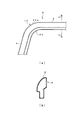
- a curved portion 10 is formed at a portion connecting the front pillar 1 and the roof pillar 2 of the pipe member 9 as shown in FIG. .
- the curved portion 10 is formed, for example, by bending (bending) a linear pipe material (deformed steel pipe) 9 having a cross-sectional shape shown in FIG.
- the radius of curvature of the curve outer side 10a becomes larger than the radius of curvature of the curve inner side 10b in the curve portion 10.
- the upper limit position of the upper end 7x of the front window unit 7 is the portion of the radius stop 10x of the curve outer side 10a. Because of the limitation, the position of the upper end 7x of the front window unit 7 cannot be made higher than the radius stop 10x. For this reason, the mounting position of the front header 4 arranged in accordance with the position of the upper end 7x of the front window unit 7 cannot be increased, and the upper viewing angle (viewing elevation angle) ⁇ 1 with respect to the driver's eye point of the driver seat is the front. It is limited by the header 4.
- the position of the upper end of the front window unit 7 is higher than the rounded stop 10x of the outer round 10a of the curved portion 10. Can be brought to. Accordingly, the height of the front header 4 can be increased, and the driver's upward viewing angle ⁇ 1 is increased. However, if curved glass is used for the front window unit 7, the driver's field of view may be distorted, which may hinder accurate work.
- the front window unit 7 is arranged along the guide rail 6 with the roof pillar. If it moves to the open position horizontally supported by 2, the curved glass of the front window unit 7 will interfere with the ceiling board (refer FIG. 1) 11 provided in the roof pillar 2. FIG. For this reason, a flat glass 7 g is used for the front window unit 7.
- the upper limit position of the upper end 7x of the front window unit 7 is in a position where it hits the rounded stop 10x portion of the curve outside 10a of the curve portion 10. Limited. For this reason, the height of the front header 4 arranged in accordance with the position of the upper end 7x of the front window unit 7 is restricted, and the driver's upper viewing angle ⁇ 1 is restricted by the front header 4.
- the object of the present invention which was created in view of the above circumstances, is to make the mounting position of the front header as high as possible in the cab frame structure of a construction machine in which the front pillar and the roof pillar are configured by a single pipe. It is an object of the present invention to provide a cab frame structure for a construction machine that widens the driver's upward viewing angle.
- the invention according to claim 1 comprises a front pillar and a roof pillar constituting a cab frame of a construction machine, comprising a single pipe member having a curved portion at a connecting portion between the front pillar and the roof pillar.
- a front header is disposed outside the curved portion of the curved portion and positioned at an upper end of the front window unit accommodated in the space.
- the invention according to claim 2 is characterized in that the pipe member has an extra length portion in a circumferential direction at a front pillar portion and a roof pillar portion, and an overhang portion projecting outward from the curve portion.
- the invention according to claim 3 is the construction machine according to claim 1 or 2, wherein a circumferential length of the front pillar portion, a circumferential length of the roof pillar portion, and a circumferential length of the curved portion of the pipe material are equal.
- This is a cab frame structure.
- the invention according to claim 4 is any one of claims 1 to 3, wherein the front window unit has a guided member that engages with a guide rail provided in the tube material, and is movable along the tube material.
- the invention according to claim 5 is the cab frame structure of the construction machine according to claim 4, wherein the guide rail is formed in the extra length portion.
- the invention according to claim 6 is the cab frame structure of the construction machine according to any one of claims 1 to 5, wherein the front window unit has flat glass.
- the construction machine cab frame structure according to the present invention can exhibit the following effects.
- the curvature radius outside the curve in the curved portion of one pipe constituting the front pillar and the roof pillar is made smaller than the curvature radius inside the curve, so that A space is provided to increase the storage position of the upper end of the window unit, and the front header is located at the upper end of the front window unit stored in that space, so that the mounting position of the front header can be increased as much as possible. This can widen the driver's upward viewing angle.
- the pipe member has an extra length portion at the front pillar portion and the roof pillar portion, and has an overhang portion projecting outward from the curve portion, Since the cross-sectional area is gradually changed along the direction, a curved portion in which the curvature radius on the outside of the curve is smaller than the curvature radius on the inside of the curve can be accurately formed from a single pipe.
- the curve portion is formed from a single pipe. The expansion and contraction of the pipe material in the circumferential direction can be suppressed.
- the front window unit can be moved along the pipe material.
- the front of the cab can be opened. Therefore, the driver can directly view the target object, not through the glass, and can increase the attachment position of the front header as much as possible, so that the driver's upward viewing angle can be widened.
- the front window unit since the front window unit has flat glass, there is no distortion in the driver's field of view unlike curved glass. Therefore, the driver can view the target without distortion and can raise the attachment position of the front header as much as possible, so that the driver's upward viewing angle can be widened.
- FIG. 1 It is a whole perspective view which shows the outline of the cab frame structure of a construction machine. It is a disassembled perspective view which shows the principal part of the cab frame structure of a construction machine.
- FIG. 1 It is explanatory drawing which shows a prior art example, (a) is a side view which shows the part of the front pillar of one pipe material which comprises a part of cab frame, the part of a roof pillar, and a curve part, (b) is b of (a).
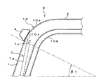
- FIG. It is explanatory drawing which shows a prior art example, and is a side view of the part of the front pillar of a pipe material, the part of a roof pillar, a curve part, a front window unit, and a front header.
- FIG. 5A is a partially enlarged view of FIG. 5
- FIG. 5B is a sectional view taken along line bb in FIG. 5A
- FIG. 5C is a sectional view taken along line cc in FIG.
- FIG. 4C is a sectional view taken along line cc of FIG.
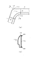
- transformation embodiment of this invention (a) is the side view of the part of the front pillar of a pipe material, the part of a roof pillar, and a curve part, (b) is the bb sectional view taken on the line bb of (a).
- FIG. 4C is a sectional view taken along line cc of FIG.
- transformation embodiment of this invention (a) is the side view of the part of the front pillar of a pipe material, the part of a roof pillar, and a curve part, (b) is the bb sectional view taken on the line bb of (a).
- FIG. 4C is a sectional view taken along line cc of FIG. It is explanatory drawing which shows the comparative example which is not embodiment of this invention, (a) is a side view of the part of the front pillar of a pipe material, the part of a roof pillar, and a curve part, (b) is the bb sectional view taken on the line bb of (a).
- FIG. 1 is a side view of the part of the front pillar of a pipe material, the part of a roof pillar, and a curve part
- the front pillar 1 and the roof pillar 2 constituting the cab frame have a curved portion 10 at a connecting portion between the front pillar 1 and the roof pillar 2. It is comprised from the one pipe material 9, and has the same component as what was already described using FIG. 1, FIG. Therefore, the same components are denoted by the same reference numerals, description thereof is omitted, and only differences, that is, features will be described.
- the cab frame structure according to the present embodiment is characterized in that the curved portion 10 of the tubular material 9 has a curved radius 10 on the curved outer side 10a smaller than that of the curved inner side 10b.
- a space 12 for increasing the accommodation position of the upper end 7 x of the front window unit 7 is provided, and the front header 4 is arranged in accordance with the position of the upper end 7 x of the front window unit 7 accommodated in the space 12.
- the mounting position of the front header 4 can be made higher than that of the conventional example shown in FIG. 4, and the driver's upper viewing angle ⁇ 2 can be made wider than the upper viewing angle ⁇ 1 of the conventional example shown in FIG. This point will be described in detail below.
- flat glass 7g is used for the glass of the front window unit 7 instead of curved glass in order to suppress distortion of the driver's field of view.
- the upper limit position of the upper end 7x of the front window unit 7 is limited to a height that abuts against the rounded stop 10x portion of the curve outside 10a of the curve portion 10.
- the front header 4 arranged in accordance with the position of the upper end 7x of the front window unit 7 is the rounded portion 10a on the curve outer side 10a of the curve portion 10 in the present embodiment shown in FIG. 5 and the conventional example shown in FIG. It is arranged at the portion of the stop 10x.
- the radius of curvature of the curve outer side 10a of the curve portion 10 is smaller than the radius of curvature of the curve inner side 10b, as shown in FIG.
- the position of the radius stop 10x of the curve outer side 10a is higher than that of the conventional example in which is larger than the curvature radius of the curve inner side 10b.
- the height of the front header 4 disposed at the portion of the radius stop 10x is higher in the present embodiment shown in FIG. 5 than in the conventional example shown in FIG. Therefore, the upper viewing angle ⁇ 2 of the driver of this embodiment shown in FIG. 5 is wider than the upper viewing angle ⁇ 1 of the conventional example shown in FIG.
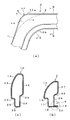
- the pipe member 9 having the curved portion 10 described above has an extra length portion 13 in the circumferential direction at the roof pillar 2 portion as shown in FIG. 6 (b).
- the curved portion 10 has a protruding portion 14 that protrudes outside the curve, and although not shown, an extra length portion 13 similar to that shown in FIG. 6B is provided in the front pillar 1 portion.
- the cross section is gradually changed along the longitudinal direction.
- the tubular material 9 having the curved portion 10 shown in FIG. 6A is a tubular material having a cross-sectional shape having a step-like surplus length portion 13 in the circumferential direction as shown in FIG. 6B (linear deformed steel pipe). Is obtained by molding (deforming), but at the time of molding, the surplus portion 13 is projected to the curve outer side 10a, thereby forming the projecting portion 14 of the curve portion 10.
- the convex circumferential length (portion including the extra length portion 13) shown in the imaginary line x in FIG. 6B is shown in FIG. 6C and in the imaginary line y. It moves to the part (part including the overhang
- the curve part 10 whose curvature radius of the curve outer side 10a is smaller than the curvature radius of the curve inner side 10b can be shape
- the phantom line z in FIG. 6 (a) depicts a concentric circle of R on the curve inner side 10b on the curve outer side 10a of the curve part 10.
- FIG. Normally, when the pipe material is bent (bent), the imaginary line z is formed on the curve outer side 10a of the curve portion 10, and the curvature radius of the curve outer side 10a becomes larger than the curvature radius of the curve inner side 10b.
- a tubular member (straight tubular member) having a cross-sectional shape having a step-like extra length portion 13 in the circumferential direction is formed (deformed).
- the curvature radius of the curve outer side 10a of the curve portion 10 can be set as shown by a solid line in FIG. It is smaller than the curvature radius of the curve inner side 10b.
- peripheral length is equal is a concept including a “peripheral length is substantially equal” state in which there is a slight difference in the peripheral length that is inevitably generated when the pipe material is formed (deformed).
- the front window unit 7 has a guided member 8 (for example, a guide roller, a protrusion, etc.) that engages with a guide rail 6 provided on the tube material 9, and can move along the tube material 9. It has become.
- the front window unit 7 moves along the front pillar 1 and the roof pillar 2 by the guided member 8 being guided by the guide rail 6, and is closed to the roof pillar 2 and is supported in a standing state on the front pillar 1.
- the front position of the cab is opened and closed by switching to an open position supported in a horizontal state. By opening the front surface of the cab, the driver in the cab can perform an accurate work by directly observing the target rather than through the glass, and in addition, the mounting position of the front header 4 is increased as much as possible. Therefore, the driver's upper viewing angle ⁇ 2 can be widened.
- the guide rail 6 may be formed in the extra length portion 13 shown in FIG. The case where the guide rail 6 is formed in the surplus length portion 13 will be described.
- the roof pillar 2 portion of the pipe material 9 (the same applies to the front pillar 1 portion) is substantially perpendicular to the outer curved surface portion 15 and from the lower end of the outer curved surface portion 15 toward the inside of the cab.
- An extended outer stepped portion 16 an outer flat portion 17 extending from the outer stepped portion 16 downward at a substantially right angle, and a lower portion extended from the outer flat portion 17 inward at a substantially right angle.
- an inner upper flat portion 21 extending upward from the inner stepped portion 20 and connected to the outer curved surface portion 15.
- the edge part of the side door 22 shown in FIG. 1 is accommodated in the part of the outer step part 16 and the outer flat part 17.
- the curved portion 10 of the tube material 9 extends from the outer curved surface portion 23 constituting the projecting portion 14 and the lower end of the outer curved surface portion 23 toward the inside of the cab at a substantially right angle.
- an inner flat portion 27 that extends upward at a substantially right angle from the lower flat portion 26 and is connected to the outer curved surface portion 14.
- the edge part of the side door 22 shown in FIG. 1 is accommodated in the part of the outside step part 24 and the outside flat part 25.
- the inner stepped portion 20 in the roof pillar 2 portion of the pipe material 9 (the same applies to the front pillar 2 portion) mainly includes the extra length portion 13. Will be composed.
- a part of the guide rail 6 can also be used as the inner stepped portion 20, that is, the extra length portion 13. That is, as shown in FIG. 6B, a guide rail is formed by the chevron steel 28 and the inner step part 20 by attaching a steel material 28 having a chevron cross section (a chevron steel with a sharp top) to the inner lower flat part 19. 6 can be configured.
- the guided member 8 of the front window unit 7 shown in FIG. 2 is engaged with the guide rail 6 and guided along the longitudinal direction of the tube material 9.
- the guided member 8 may be a tapered roller, a tapered protrusion, or the like that matches the inclination. In this way, by forming a part of the guide rail 6 in the surplus length portion 13 and combining the function of the guide rail 6, compared to the case where the surplus length portion 13 and the guide rail 6 are provided completely separately, Cost reduction can be promoted.
- FIG. 7 shows a first modified embodiment of the present invention.
- the cab frame structure of the construction machine according to the first modified embodiment has the same basic configuration as the cab frame structure of the construction machine of the previous embodiment described with reference to FIGS.
- FIG. 7B and FIG. 7B only the cross-sectional shape of the roof pillar 2 portion of the tube material 9 shown in FIG. 6B (the same applies to the front pillar 1 portion) is the previous embodiment. And different. Therefore, only the difference will be described, and the same components are denoted by the same reference numerals and description thereof will be omitted.
- the roof pillar 2 portion of the pipe material 9 (the same applies to the front pillar 1 portion) is substantially perpendicular to the outer curved surface portion 15 and from the lower end of the outer curved surface portion 15 toward the inside of the cab.
- the outer stepped portion 16 extended to the outer side, the outer flat portion 17 extended downward from the outer stepped portion 16 at a substantially right angle, and the outer flat portion 17 extended at a substantially right angle toward the inner side.
- the lower flat portion 18, the inner lower flat portion 29 extending substantially perpendicularly upward from the lower flat portion 18, and the inner lower step difference extending obliquely upward from the inner lower flat portion 29 outward.
- the inner lower step portion 30 and the inner upper step portion 32 mainly constitute the surplus length portion 13. Will do.
- the inner lower stepped portion 30 and the inner upper stepped portion 32 also serve as the guide rail 6, and the guided member 8 of the front window unit 7 shown in FIG. It accommodates between the part 30 and the inner upper level
- FIG. 8 shows a second modified embodiment of the present invention.
- the cab frame structure of the construction machine according to the second modified embodiment has the same basic configuration as the cab frame structure of the construction machine of the first embodiment described with reference to FIGS. 6 (b) and FIG. 8 (b), and FIG. 6 (c) and FIG. 8 (c) are clearly compared, the portion of the roof pillar 2 (front pillar 1) of the tube material 9 shown in FIG. 6 (b).
- This also applies to the first embodiment
- only the cross-sectional shape of the curved portion 10 shown in FIG. 6C is different from the first embodiment. Therefore, only the difference will be described, and the same components are denoted by the same reference numerals and description thereof will be omitted.
- the roof pillar 2 portion of the pipe material 9 (the same applies to the front pillar 1 portion) is substantially perpendicular to the outer curved surface portion 15 and from the lower end of the outer curved surface portion 15 toward the inside of the cab.
- the outer stepped portion 16 extended to the outer side, the outer flat portion 17 extended downward from the outer stepped portion 16 at a substantially right angle, and the outer flat portion 17 extended at a substantially right angle toward the inner side.
- an inner upper step portion 36 extending upward from the inner step portion 36 and connected to the outer curved surface portion 15.
- the curved portion 10 of the tube material 9 extends from the outer curved surface portion 23 constituting the protruding portion 14 and the lower end of the outer curved surface portion 23 toward the inside of the cab at a substantially right angle.
- An inner lower flat portion 38 extending substantially perpendicularly upward from the lower flat portion 26, an inner stepped portion 39 extending obliquely upward from the inner lower flat portion 38, and an inner side
- An inner upper flat portion 40 extending upward from the step portion 39 and connected to the outer curved surface portion 23 is provided.
- the folded portion 34 in the portion of the roof pillar 2 of the tube material 9 (the same applies to the portion of the front pillar 1) is provided.
- the extra length portion 13 is mainly configured.
- the folded portion 34, that is, the extra length portion 13 also serves as the guide rail 6, and the guided member 8 of the front window unit 7 is disposed between the folded portion 34 and the inner stepped portion 36 shown in FIG. Is housed.
- cost reduction can be promoted compared with the case where the surplus length part 13 and the guide rail 6 are provided separately.
- the basic operational effects of the second modified embodiment are the same as those of the first embodiment, and thus description thereof is omitted.
- the long portion 13 is projected at the curved portion 10 to the curved outer side 10 a to form a projected portion 14.
- These embodiments are like an inner stepped portion 20 shown in FIG. 6B, an inner lower stepped portion 30 and an inner upper stepped portion 32 shown in FIG. 7B, and a folded portion 34 shown in FIG. 8B.
- the shape that functions as the guide rail 6 is used as the extra length portion 13 in the basic cross section
- the front pillar 1, the curved portion 10, and the roof pillar 2 are not formed of a single pipe material as in the present invention, but are made as separate parts.
- the curved portion 10 may be formed of a hollow body formed by spot welding the inner panel 10p and the outer panel 10q, and the radius of curvature of the curved outer side 10a of the curved portion 10 is set to the curvature of the curved inner side 10b. It is possible to make it smaller than the radius.
- the hollow body forming the curved portion 10 since the hollow body forming the curved portion 10 has a panel structure joined only by the spot welded portion SW, the strength is lower than that of the integrated product. Moreover, since it is necessary to weld the front pillar 1 (pipe material), the curve part 10 (panel structure hollow body), and the roof pillar 2 (pipe material) at the connection part, the appearance of the weld joint part (weld part W) is poor, A decrease in strength is inevitable at the weld W. Further, since welding distortion occurs, the accuracy is not stable, and the assemblability to the cab frame is poor. In addition, since it is an assembly structure in which a plurality of parts are assembled, the number of assembling steps increases and the cost increases.
- the front pillar 1, the curved portion 10, and the roof pillar 2 are integrated with each other by molding a single pipe, so that it is necessary for the divided panel type of FIG.
- the welded portion W and the spot welded portion SW do not exist, and a cab (cab frame) excellent in strength can be provided.
- the accuracy is stable, and the assemblability to the cab frame is good.
- the grinder processing for finishing them becomes unnecessary and the appearance is good. The number of man-hours involved in assembling the cab frame can be reduced and cost reduction can be promoted.
Landscapes
- Engineering & Computer Science (AREA)
- Mining & Mineral Resources (AREA)
- Civil Engineering (AREA)
- General Engineering & Computer Science (AREA)
- Structural Engineering (AREA)
- Body Structure For Vehicles (AREA)
- Component Parts Of Construction Machinery (AREA)
Priority Applications (3)
| Application Number | Priority Date | Filing Date | Title |
|---|---|---|---|
| CN201180037211.7A CN103140633B (zh) | 2010-07-29 | 2011-07-21 | 建筑机械的驾驶室框架结构 |
| DE112011102533.5T DE112011102533B4 (de) | 2010-07-29 | 2011-07-21 | Kabinenrahmenstruktur für eine Baumaschine |
| US13/811,542 US8876196B2 (en) | 2010-07-29 | 2011-07-21 | Cab frame structure for construction machine |
Applications Claiming Priority (2)
| Application Number | Priority Date | Filing Date | Title |
|---|---|---|---|
| JP2010-170767 | 2010-07-29 | ||
| JP2010170767A JP5706110B2 (ja) | 2010-07-29 | 2010-07-29 | 建設機械のキャブフレーム構造 |
Publications (1)
| Publication Number | Publication Date |
|---|---|
| WO2012014781A1 true WO2012014781A1 (ja) | 2012-02-02 |
Family
ID=45529993
Family Applications (1)
| Application Number | Title | Priority Date | Filing Date |
|---|---|---|---|
| PCT/JP2011/066589 Ceased WO2012014781A1 (ja) | 2010-07-29 | 2011-07-21 | 建設機械のキャブフレーム構造 |
Country Status (5)
| Country | Link |
|---|---|
| US (1) | US8876196B2 (https=) |
| JP (1) | JP5706110B2 (https=) |
| CN (1) | CN103140633B (https=) |
| DE (1) | DE112011102533B4 (https=) |
| WO (1) | WO2012014781A1 (https=) |
Families Citing this family (4)
| Publication number | Priority date | Publication date | Assignee | Title |
|---|---|---|---|---|
| USD751123S1 (en) | 2014-12-19 | 2016-03-08 | One Fifty Labs Inc. | Operator cab |
| CA2875553A1 (en) | 2014-12-19 | 2016-06-19 | Metalboss Labs Inc. | Operator cabs and methods for constructing same |
| US10550546B2 (en) * | 2018-03-26 | 2020-02-04 | Komatsu Ltd. | Cover of work vehicle, cab of work vehicle, and work vehicle |
| CN109482684B (zh) * | 2018-11-15 | 2020-07-17 | 陕西宏象房车科技发展有限公司 | 房车框架的弯折成型工艺 |
Citations (4)
| Publication number | Priority date | Publication date | Assignee | Title |
|---|---|---|---|---|
| JP2002088810A (ja) * | 2000-09-14 | 2002-03-27 | Komatsu Ltd | 建設機械の運転室前部窓 |
| JP2002088812A (ja) * | 2000-09-18 | 2002-03-27 | Hitachi Constr Mach Co Ltd | 建設機械用キャブ |
| JP2005247006A (ja) * | 2004-03-01 | 2005-09-15 | Komatsu Ltd | 作業機械の運転室構造 |
| JP2007099236A (ja) * | 2005-10-07 | 2007-04-19 | Shin Caterpillar Mitsubishi Ltd | キャブおよび作業機械 |
Family Cites Families (53)
| Publication number | Priority date | Publication date | Assignee | Title |
|---|---|---|---|---|
| US5096253A (en) * | 1990-05-31 | 1992-03-17 | Samsung Heavy Industries, Co., Ltd. | Cabs of heavy construction vehicles with an openable front window and a locking device therefor |
| JPH0612556U (ja) * | 1992-07-21 | 1994-02-18 | 株式会社小松製作所 | 建設機械の運転室 |
| WO1999032734A1 (en) * | 1997-12-22 | 1999-07-01 | Hitachi Construction Machinery Co., Ltd. | Swinging construction machine, and cab, equipment cover and counter-weight used for the machine |
| DE60001403T2 (de) * | 2000-07-28 | 2003-10-30 | Same Deutz-Fahr S.P.A., Treviglio | Kabinerahmen für landwirtschaftliche Maschine |
| DE60130128T2 (de) * | 2000-09-18 | 2008-05-15 | Hitachi Construction Machinery Co., Ltd. | Fahrerhaus für erdbewegungsmaschinen |
| US6568746B2 (en) * | 2000-09-18 | 2003-05-27 | Hitachi Construction Machinery Co., Ltd. | Cab for construction machinery |
| DE10118344A1 (de) * | 2001-04-12 | 2002-10-17 | Daimler Chrysler Ag | Modular aufgebaute Fahrerhaus-Baureihe für Lastkraftwagen |
| US6772544B2 (en) * | 2002-03-28 | 2004-08-10 | Kubota Corporation | Wheeled work vehicle |
| JP2004042739A (ja) * | 2002-07-10 | 2004-02-12 | Komatsu Ltd | 作業車両における運転室 |
| JP2004090039A (ja) * | 2002-08-30 | 2004-03-25 | Komatsu Ltd | キャブフレーム用異形断面管材の曲げ加工方法 |
| JP4201126B2 (ja) * | 2003-04-10 | 2008-12-24 | 株式会社小松製作所 | 建設機械のキャブ |
| US7140670B2 (en) * | 2003-08-19 | 2006-11-28 | Custom Products Of Litchfield | Interconnection system for overhead frame structures |
| EP1666343B1 (en) * | 2003-09-09 | 2009-07-15 | Komatsu Ltd. | Cab of construction machinery |
| US7216926B2 (en) * | 2003-10-22 | 2007-05-15 | Hampel Lance T | Vehicle cab |
| JP4209787B2 (ja) * | 2004-02-26 | 2009-01-14 | 日立建機株式会社 | 建設機械 |
| WO2005121459A1 (ja) * | 2004-06-07 | 2005-12-22 | Hitachi Construction Machinery Co., Ltd. | 建設機械 |
| WO2006008985A1 (ja) * | 2004-07-16 | 2006-01-26 | Komatsu Ltd. | 建設機械のキャブ |
| US20060017308A1 (en) * | 2004-07-22 | 2006-01-26 | Kobelco Construction Machinery Co., Ltd. | Driver's cabin of construction machine |
| JP4999689B2 (ja) * | 2005-07-19 | 2012-08-15 | 株式会社小松製作所 | 建設機械のキャブ構造 |
| US7770963B2 (en) * | 2005-07-19 | 2010-08-10 | Komatsu Ltd. | Cab structure for construction machine |
| JP4804078B2 (ja) * | 2005-09-06 | 2011-10-26 | 株式会社小松製作所 | 建設機械のキャブ構造 |
| JP2007106286A (ja) * | 2005-10-14 | 2007-04-26 | Kobelco Contstruction Machinery Ltd | 作業機械のキャブ |
| JP4343900B2 (ja) * | 2005-12-26 | 2009-10-14 | 日立建機株式会社 | 建設機械 |
| USD555677S1 (en) * | 2006-03-24 | 2007-11-20 | Kubota Corporation | Cabin for work machine |
| USD549245S1 (en) * | 2006-09-22 | 2007-08-21 | Saf-T-Cab, Inc. | Off highway mobile equipment cab |
| JP5325578B2 (ja) * | 2006-10-16 | 2013-10-23 | 株式会社小松製作所 | パイプの補強構造およびこれを備えた建設機械のキャブ構造 |
| ATE522671T1 (de) * | 2006-11-28 | 2011-09-15 | Hitachi Construction Machinery | Baumaschine |
| USD548753S1 (en) * | 2006-11-29 | 2007-08-14 | Volvo Construction Equipment Holding Sweden Ab | Cabin for heavy construction equipment |
| DE202007006500U1 (de) * | 2007-05-07 | 2008-09-18 | Liebherr-Hydraulikbagger Gmbh | Baumaschine |
| JP4966100B2 (ja) * | 2007-05-31 | 2012-07-04 | 日立建機株式会社 | 建設機械 |
| USD571073S1 (en) * | 2007-07-06 | 2008-06-10 | Crown Equipment Corporation | Fork lift truck |
| USD571074S1 (en) * | 2007-07-06 | 2008-06-10 | Crown Equipment Corporation | Overhead guard for a fork lift truck |
| EP2180100B1 (en) * | 2007-08-13 | 2012-10-24 | Hitachi Construction Machinery Co., Ltd | Construction machine |
| JP5172381B2 (ja) * | 2008-02-22 | 2013-03-27 | 日立建機株式会社 | 建設機械 |
| KR101307286B1 (ko) * | 2008-07-16 | 2013-09-11 | 가부시키가이샤 고마쓰 세이사쿠쇼 | 건설 기계의 캡 |
| JP5088268B2 (ja) * | 2008-08-11 | 2012-12-05 | コベルコ建機株式会社 | キャブ及びこれを備えた移動式建設機械 |
| USD594480S1 (en) * | 2008-09-30 | 2009-06-16 | Clark Equipment Company | Telehandler cab |
| JP5108709B2 (ja) * | 2008-09-30 | 2012-12-26 | 株式会社神戸製鋼所 | 建設機械のキャビン防音装置 |
| WO2010050469A1 (ja) * | 2008-10-30 | 2010-05-06 | 株式会社小松製作所 | 建設機械用のキャブ |
| JP4821895B2 (ja) * | 2009-07-29 | 2011-11-24 | コベルコ建機株式会社 | 建設機械 |
| JP5234693B2 (ja) * | 2009-10-16 | 2013-07-10 | 日立建機株式会社 | 建設機械 |
| KR101745530B1 (ko) * | 2009-11-20 | 2017-06-09 | 가부시키가이샤 히다치 겡키 티에라 | 건설 기계 |
| WO2011118285A1 (ja) * | 2010-03-24 | 2011-09-29 | 日立建機株式会社 | 建設機械 |
| JP5054802B2 (ja) * | 2010-05-24 | 2012-10-24 | 日立建機株式会社 | 建設機械 |
| JP5054805B2 (ja) * | 2010-06-09 | 2012-10-24 | 日立建機株式会社 | 建設機械 |
| CN102947512B (zh) * | 2010-06-15 | 2015-05-27 | 日立建机株式会社 | 电动式工程机械 |
| JP5418425B2 (ja) * | 2010-07-01 | 2014-02-19 | コベルコ建機株式会社 | キャビンのドア |
| JP5077411B2 (ja) * | 2010-09-14 | 2012-11-21 | コベルコ建機株式会社 | 建設機械における機器類の脱着構造及び同脱着方法 |
| JP5356341B2 (ja) * | 2010-09-16 | 2013-12-04 | 日立建機株式会社 | 建設機械 |
| JP5516439B2 (ja) * | 2011-01-25 | 2014-06-11 | コベルコ建機株式会社 | 建設機械 |
| US8807635B2 (en) * | 2011-02-11 | 2014-08-19 | Cnh Industrial America Llc | Self-cleaning cab floor |
| JP5810683B2 (ja) * | 2011-07-04 | 2015-11-11 | コベルコ建機株式会社 | 建設機械のキャブ支持構造 |
| JP5118259B1 (ja) * | 2012-03-30 | 2013-01-16 | 株式会社小松製作所 | キャブ |
-
2010
- 2010-07-29 JP JP2010170767A patent/JP5706110B2/ja active Active
-
2011
- 2011-07-21 WO PCT/JP2011/066589 patent/WO2012014781A1/ja not_active Ceased
- 2011-07-21 DE DE112011102533.5T patent/DE112011102533B4/de active Active
- 2011-07-21 US US13/811,542 patent/US8876196B2/en not_active Expired - Fee Related
- 2011-07-21 CN CN201180037211.7A patent/CN103140633B/zh active Active
Patent Citations (4)
| Publication number | Priority date | Publication date | Assignee | Title |
|---|---|---|---|---|
| JP2002088810A (ja) * | 2000-09-14 | 2002-03-27 | Komatsu Ltd | 建設機械の運転室前部窓 |
| JP2002088812A (ja) * | 2000-09-18 | 2002-03-27 | Hitachi Constr Mach Co Ltd | 建設機械用キャブ |
| JP2005247006A (ja) * | 2004-03-01 | 2005-09-15 | Komatsu Ltd | 作業機械の運転室構造 |
| JP2007099236A (ja) * | 2005-10-07 | 2007-04-19 | Shin Caterpillar Mitsubishi Ltd | キャブおよび作業機械 |
Also Published As
| Publication number | Publication date |
|---|---|
| JP5706110B2 (ja) | 2015-04-22 |
| JP2012031606A (ja) | 2012-02-16 |
| US20130119708A1 (en) | 2013-05-16 |
| DE112011102533T5 (de) | 2013-05-02 |
| DE112011102533B4 (de) | 2016-01-21 |
| CN103140633B (zh) | 2016-01-20 |
| US8876196B2 (en) | 2014-11-04 |
| CN103140633A (zh) | 2013-06-05 |
Similar Documents
| Publication | Publication Date | Title |
|---|---|---|
| US11254366B2 (en) | Vehicle body joint structure | |
| US9168956B2 (en) | Vehicle body having rear side member | |
| JP5706110B2 (ja) | 建設機械のキャブフレーム構造 | |
| JP5873106B2 (ja) | 車両の意匠部品配置構造 | |
| JP6156291B2 (ja) | 車両用ドア構造 | |
| CN103568787A (zh) | 车门框架结构 | |
| GB2428645A (en) | Fixing arrangement for side spoiler | |
| JP2010047226A (ja) | 車両用バンパ装置 | |
| JP5236717B2 (ja) | 車両の後部車体 | |
| US10988005B2 (en) | Vehicle door structure and method for manufacturing the same | |
| WO2015056623A1 (ja) | ドアフレーム | |
| WO2019087903A1 (ja) | ドアサッシュ構造 | |
| US6533347B2 (en) | Front chassis structure for a vehicle | |
| KR20210076588A (ko) | 차체 조인트 구조 | |
| JP6863246B2 (ja) | 車両後部構造 | |
| JP2009035095A (ja) | ピラー上部構造 | |
| JP6869278B2 (ja) | 車両側部構造 | |
| JP4313238B2 (ja) | 熱交換器のファンシュラウド | |
| JP2014131888A (ja) | 自動車の車体 | |
| JP4354331B2 (ja) | 車両のカウル構造 | |
| JP6473436B2 (ja) | 車体構造 | |
| JP7839482B2 (ja) | 車体後部構造 | |
| JPWO2009037789A1 (ja) | バンパーリインフォースメント | |
| JP2020006859A (ja) | 車両用フロントピラーの周辺構造 | |
| JP2022185939A (ja) | インパクトビーム |
Legal Events
| Date | Code | Title | Description |
|---|---|---|---|
| WWE | Wipo information: entry into national phase |
Ref document number: 201180037211.7 Country of ref document: CN |
|
| 121 | Ep: the epo has been informed by wipo that ep was designated in this application |
Ref document number: 11812372 Country of ref document: EP Kind code of ref document: A1 |
|
| WWE | Wipo information: entry into national phase |
Ref document number: 13811542 Country of ref document: US |
|
| WWE | Wipo information: entry into national phase |
Ref document number: 1120111025335 Country of ref document: DE Ref document number: 112011102533 Country of ref document: DE |
|
| 122 | Ep: pct application non-entry in european phase |
Ref document number: 11812372 Country of ref document: EP Kind code of ref document: A1 |