WO2012014742A1 - 開閉装置 - Google Patents
開閉装置 Download PDFInfo
- Publication number
- WO2012014742A1 WO2012014742A1 PCT/JP2011/066422 JP2011066422W WO2012014742A1 WO 2012014742 A1 WO2012014742 A1 WO 2012014742A1 JP 2011066422 W JP2011066422 W JP 2011066422W WO 2012014742 A1 WO2012014742 A1 WO 2012014742A1
- Authority
- WO
- WIPO (PCT)
- Prior art keywords
- housing
- slide
- plate
- slide plate
- moving plate
- Prior art date
Links
Images


Classifications
-
- H—ELECTRICITY
- H04—ELECTRIC COMMUNICATION TECHNIQUE
- H04B—TRANSMISSION
- H04B1/00—Details of transmission systems, not covered by a single one of groups H04B3/00 - H04B13/00; Details of transmission systems not characterised by the medium used for transmission
- H04B1/38—Transceivers, i.e. devices in which transmitter and receiver form a structural unit and in which at least one part is used for functions of transmitting and receiving
- H04B1/40—Circuits
-
- H—ELECTRICITY
- H04—ELECTRIC COMMUNICATION TECHNIQUE
- H04M—TELEPHONIC COMMUNICATION
- H04M1/00—Substation equipment, e.g. for use by subscribers
- H04M1/02—Constructional features of telephone sets
- H04M1/0202—Portable telephone sets, e.g. cordless phones, mobile phones or bar type handsets
- H04M1/0206—Portable telephones comprising a plurality of mechanically joined movable body parts, e.g. hinged housings
- H04M1/0208—Portable telephones comprising a plurality of mechanically joined movable body parts, e.g. hinged housings characterized by the relative motions of the body parts
- H04M1/0214—Foldable telephones, i.e. with body parts pivoting to an open position around an axis parallel to the plane they define in closed position
- H04M1/0216—Foldable in one direction, i.e. using a one degree of freedom hinge
-
- G—PHYSICS
- G06—COMPUTING; CALCULATING OR COUNTING
- G06F—ELECTRIC DIGITAL DATA PROCESSING
- G06F1/00—Details not covered by groups G06F3/00 - G06F13/00 and G06F21/00
- G06F1/16—Constructional details or arrangements
- G06F1/1613—Constructional details or arrangements for portable computers
- G06F1/1615—Constructional details or arrangements for portable computers with several enclosures having relative motions, each enclosure supporting at least one I/O or computing function
- G06F1/1624—Constructional details or arrangements for portable computers with several enclosures having relative motions, each enclosure supporting at least one I/O or computing function with sliding enclosures, e.g. sliding keyboard or display
-
- H—ELECTRICITY
- H04—ELECTRIC COMMUNICATION TECHNIQUE
- H04M—TELEPHONIC COMMUNICATION
- H04M1/00—Substation equipment, e.g. for use by subscribers
- H04M1/02—Constructional features of telephone sets
-
- H—ELECTRICITY
- H04—ELECTRIC COMMUNICATION TECHNIQUE
- H04M—TELEPHONIC COMMUNICATION
- H04M1/00—Substation equipment, e.g. for use by subscribers
- H04M1/02—Constructional features of telephone sets
- H04M1/0202—Portable telephone sets, e.g. cordless phones, mobile phones or bar type handsets
- H04M1/0206—Portable telephones comprising a plurality of mechanically joined movable body parts, e.g. hinged housings
- H04M1/0208—Portable telephones comprising a plurality of mechanically joined movable body parts, e.g. hinged housings characterized by the relative motions of the body parts
- H04M1/0235—Slidable or telescopic telephones, i.e. with a relative translation movement of the body parts; Telephones using a combination of translation and other relative motions of the body parts
- H04M1/0237—Sliding mechanism with one degree of freedom
-
- H—ELECTRICITY
- H04—ELECTRIC COMMUNICATION TECHNIQUE
- H04M—TELEPHONIC COMMUNICATION
- H04M1/00—Substation equipment, e.g. for use by subscribers
- H04M1/02—Constructional features of telephone sets
- H04M1/0202—Portable telephone sets, e.g. cordless phones, mobile phones or bar type handsets
- H04M1/0206—Portable telephones comprising a plurality of mechanically joined movable body parts, e.g. hinged housings
- H04M1/0208—Portable telephones comprising a plurality of mechanically joined movable body parts, e.g. hinged housings characterized by the relative motions of the body parts
- H04M1/021—Portable telephones comprising a plurality of mechanically joined movable body parts, e.g. hinged housings characterized by the relative motions of the body parts using combined folding and rotation motions
- H04M1/0212—Portable telephones comprising a plurality of mechanically joined movable body parts, e.g. hinged housings characterized by the relative motions of the body parts using combined folding and rotation motions with a two degrees of freedom mechanism, i.e. folding around a first axis and rotating around a second axis perpendicular to the first
Definitions
- the present invention relates to an opening and closing device, and more particularly to an opening and closing device capable of opening a first housing and a second housing in a so-called full flat.
- a portable terminal device represented by a portable terminal device has a first case (fixed plate) provided with a numeric keypad and the like, and the liquid crystal display device etc. provided and can be opened and closed with respect to the first case And the second case (moving plate). Further, as a structure for opening and closing the second housing with respect to the first housing, the first housing and the second housing are connected by a hinge mechanism, and the second housing is rotated with respect to the first housing.
- a type that is opened and closed by folding (folding type) and a type that is opened and closed by sliding the second casing with respect to the first casing (sliding type) are common.
- the liquid crystal display device is hidden in the folded state, and the liquid crystal display device can not be used in the folded state. Further, in the slide type portable terminal device, the above-mentioned problem of the fold type does not occur, but in the open state, the first housing and the second housing inevitably overlap, which prevents effective use of space. There is a problem.
- a more specific object of the present invention is to provide an opening and closing device capable of stably and smoothly performing a movement operation between the closed position and the open position of the second housing in one operation.
- the switchgear is: A fixed frame having a bearing portion and fixed to the first housing; A movable plate rotatably movable relative to the fixed frame; A slide plate which is slidable relative to the moving plate and fixed to the second housing; An arm having one end pivotally supported by the bearing and the other end pivotally supported by the moving plate, and having a plurality of arms of the same length disposed between the bearing and the moving plate; And a slide mechanism for sliding the slide plate relative to the moving plate, The slide plate slides relative to the movable plate by the slide mechanism, and the movable plate rotates relative to the fixed frame as the arm rotates, whereby the second housing and the first housing
- the second housing is configured to move from an overlapping closed position to an open position where the second housing is flat with the first housing.
- the plurality of arms may be arranged in parallel with each other between the bearing portion and the moving plate.
- a force is applied to at least one of the arms in the return direction until the arms are rotated from the closed position or the open position to the predetermined reverse position, and in the forward direction when the reverse position is exceeded.
- a first semi-automatic mechanism for biasing force may be provided.
- the slide mechanism applies a force in the return direction until the slide plate is slid from the slide start position to the predetermined reverse position, and biases the force in the forward direction when the reverse position is exceeded.
- the second semi-automatic mechanism may be provided.
- the present invention it is possible to stably open and close the second housing with respect to the first housing while maintaining the horizontal state of the second housing, and at the same time the second housing is in the closed position and the open position. Can be moved between
- FIG. 8 is an exploded perspective view for explaining a first modification of the switchgear sliding mechanism according to the embodiment of the present invention.
- FIG. 9 is an exploded perspective view for explaining a second modification of the switchgear sliding mechanism according to the embodiment of the present invention.
- FIG. 10 is an exploded perspective view for explaining a third modification of the switchgear sliding mechanism according to the embodiment of the present invention.
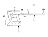
- FIG. 1 to 3 are views for explaining a switching device 10 according to an embodiment of the present invention
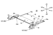
- FIG. 1 is a perspective view of the switching device 10
- FIG. 2 is an exploded perspective view of the switching device 10
- FIG. 3 is an exploded perspective view for explaining a slide mechanism 22 and the like of the opening and closing device 10.
- the switching device 10 is applied to, for example, an electronic device 1 as shown in FIG. 7A.
- the electronic device 1 is a portable terminal device, and includes a first housing 2, a second housing 3, and the opening / closing device 10 according to the present embodiment.
- a keyboard, a liquid crystal display device, etc. are provided on the upper surface of the first housing 2.
- a liquid crystal display device or the like is provided on the upper surface of the second housing 3.
- the electronic device 1 When carrying a portable terminal device, it is necessary to reduce its shape to improve portability. Therefore, the electronic device 1 according to the present embodiment is configured to slide the second housing 3 with respect to the first housing 2 between the closed position and the open position by providing the opening / closing device 10.
- FIG. 7A shows a state in which the second housing 3 is in the closed position (hereinafter referred to as the closed state), and FIG. 7D shows a state in which the second housing 3 is in the open position (hereinafter referred to as the open state).
- the closed state the second housing 3 is in a state of overlapping the top of the first housing 2.
- the area in plan view of the electronic device 1 in the closed state is the area in the open state. It is half. Therefore, in the closed state, the electronic device 1 has a small size, and portability is secured.
- the second housing 3 is moved from the closed position to the open position by the opening / closing device 10 as described in detail later, and the upper surface 2a of the first housing 2 and the upper surface 3a of the second housing 3 Are held in the same plane.
- the first housing 2 and the second housing 3 do not overlap, but are arranged in parallel on the same plane.
- the casings 2 and 3 do not overlap, and the entire upper surfaces 2a and 3a of the casings 2 and 3 are exposed upward. Therefore, the entire surface of the upper surface 2a of the first housing 2 and the entire surface of the upper surface 3a of the second housing 3 can be used as installation positions of components of the electronic device 1.
- the entire upper surface of the first housing 2 and the entire upper surface of the second housing 3 can be used as installation positions of components. The use efficiency of a few space can be improved.
- the opening / closing device 10 is constituted by a fixed frame 12, a moving plate 14, a slide plate 16, a first link arm 18, a second link arm 20, a slide mechanism 22 and the like. There is. First, the fixed frame 12 will be described.
- the fixed frame 12 is fixed to the first housing 2 of the electronic device 1.
- the fixed frame 12 is formed by press-forming a metal plate material, and a base portion 12a fixed to the first housing 2 and shaft supporting portions 12b, 12c, 12d bent at both ends of the base portion 12a. And are integrally formed.
- the respective bearing portions 12b, 12c, 12d are bent substantially at right angles with respect to the base portion 12a.
- a first link arm 18, which will be described later, is connected to a shaft pin 17 supported between the bearing portion 12b and the bearing portion 12c.
- a second link arm 20 described later is connected to a link shaft 26 axially supported by the bearing portion 12c and the bearing portion 12d. For this reason, the axial hole in which the axial pin 17 and the link shaft 26 are penetrated is formed in each axial support part 12b, 12c, 12d.
- two fixed frames 12 are provided, and they are arranged to be separated in the directions of arrows Y1 and Y2 in the drawing.
- the fixed frame 12 on the Y1 direction side is referred to as a fixed frame 12A
- the fixed frame 12 on the Y2 direction side is a fixed frame. It shall be shown and described as 12B.
- the component disposed on the Y1 direction side is also appended with “A” as necessary to its reference numeral, and the component disposed on the Y2 direction side
- the symbol “A” will be added to the code as necessary.
- the fixed frames 12A and 12B do not necessarily have to be divided into two, and the fixed frames 12A and 12B can be integrally configured by connecting the base portions 12a to each other.
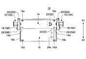
- the movable plate 14 is formed by press-forming a metal plate material, and as shown in FIG. 3, has a base portion 14a, connection portions 14b and 14c, a slide groove 14f, and the like.
- the main body portion 14a is a plate-like member extending in the directions of arrows Y1 and Y2 in the drawing.
- the connection portions 14b and 14c and the slide groove 14f are integrally formed at both ends (ends in the Y1 and Y2 directions) of the main body portion 14a.
- connection portions 14b and 14c are bent so as to extend perpendicularly upward (in the direction of the arrow Z1 in the drawing) with respect to the main body portion 14a.
- Connecting members 29 (29A, 29B) described later are disposed at the connecting portions 14b, 14c.
- stopper grooves 14d and 14e are formed at positions near four corners of the main body portion 14a.
- the stopper grooves 14d and 14e are semicircular grooves, and are formed corresponding to the arrangement positions of the stoppers 16d and 16e described later.
- the slide grooves 14f are U-shaped grooves formed at both end portions of the main body portion 14a.
- the slide groove 14f is formed by bending the end of the main body 14a downward once and then bending it inward.
- a slide portion 16b of a slide plate 16 described later is slidably attached to the slide groove 14f.
- connecting members 29 (29A, 29B) are disposed at the connecting portions 14b, 14c described above.
- the connection member 29 is a member formed by bending a metal plate material in a U-shape.
- the connecting member 29 is fixed to the connecting portions 14 b and 14 c by using a fixing member 38.
- axial holes 29 b and 29 c are formed on the side surfaces of the connecting member 29.
- the upper end portion of the first link arm 18 is rotatably connected to the shaft hole 29 b.
- the shaft hole 18a formed at the upper end of the first link arm 18 and the shaft hole 29b formed in the connecting member 29 are aligned, and the shaft pin 15 is inserted into each shaft hole 18a, 29b.
- the upper end portion of the second link arm 20 is rotatably connected to the shaft hole 29 c. Specifically, the axial holes 20a formed in the second link arm 20 and the axial holes 29c formed in the connecting member 29 are aligned, and the axial pins 19 are arranged in each axial hole 20a.
- the second link arm 20 is rotatably connected to the moving plate 14 via the connecting member 29 by inserting the connector 29c and fixing to the connecting member 29.
- the slide plate 16 is formed by pressing a metal plate material, and is fixed to the second housing 3 of the electronic device 1. Further, the slide plate 16 is movably attached to the movable plate 14, and more specifically, is configured to be slidable in the directions of arrows X1 and X2 with respect to the movable plate 14 by the slide mechanism 22.
- the slide plate 16 is configured to have a main body portion 16a, a slide portion 16b, stoppers 16d and 16e, and the like.
- the main body portion 16 a is a metal plate-like member having a rectangular shape.
- the side portions of the main body portion 16a in the Y1 direction and the Y2 direction in the drawing are formed with slide portions 16b by being bent in a step shape.
- stoppers 16d and 16e are disposed at four corner positions of the main body portion 16a.
- the stoppers 16d and 16e are cylindrical projections erected on the main body portion 16a.
- the stopper 16d is disposed on the X2 direction side of the main body portion 16a, and the stopper 16e is disposed on the X1 direction side of the main body portion 16a.
- the slide plate 16 moves in the X1 and X2 directions with respect to the moving plate 14.
- the stopper grooves 14d and 14e provided on the moving plate 14 and the stoppers 16d and 16e provided on the slide plate 16 function as a movement range restricting mechanism for restricting the movement range of the slide plate 16 with respect to the movement plate 14.
- the stopper 16d abuts on the stopper groove 14d, whereby the slide of the slide plate 16 in the X1 direction is restricted.
- the stopper 16e abuts on the stopper groove 14e, whereby the slide of the slide plate 16 in the X2 direction is restricted.
- 16d and 16e are in contact with the stopper grooves 14d and 14e. Therefore, in order to suppress the collision sound at the time of contact, it is desirable to dispose a buffer member such as rubber on the outer periphery of 16 d and 16 e.
- the slide mechanism 22 has a function of sliding the slide plate 16 in the X1 and X2 directions with respect to the moving plate 14.
- the slide mechanism 22 is configured to have a slide groove 14 f formed in the moving plate 14, a slide portion 16 b formed in the slide plate 16, a spring unit 23, a cam plate 24 and the like.
- the slide portions 16b formed on both sides (sides in the Y1 and Y2 directions) of the slide plate 16 slidably engage with the slide grooves 14f formed in the U shape in the moving plate 14
- the slide plate 16 slides in the X1 and X2 directions with respect to the moving plate 14.
- the spring unit 23 is fixed to the back surface (the surface on the arrow Z2 side) of the moving plate 14.
- the spring unit 23 includes a roller 28 and a corry spring 27 and the like.
- the spring unit 23 is configured to bias the roller 28 in the direction of the arrow Y1 in FIG.
- the cam plate 24 is fixed to the upper surface (the surface on the arrow Z1 side) of the slide plate 16.
- the cam plate 24 is provided to extend in the X1 and X2 directions along the side of the slide plate 16 in the Y1 direction.
- cam grooves 24a and 24b and a cam surface 24c are formed.
- the cam grooves 24a and 24b are disposed on the cam plate 24 so as to be separated in the X1 and X2 directions, and a cam surface 24c is formed between the pair of cam grooves 24a and 24b.
- the cam surface 24 c is in the form of a linear cam having no unevenness in the surface direction.
- the spring unit 23 is configured such that the roller 28 engages with the cam grooves 24 a and 24 b or the cam surface 24 c of the cam plate 24 in a state where the slide plate 16 is mounted on the moving plate 14. That is, the roller 28 provided in the spring unit 23 is configured to be in pressure contact with the cam plate 24 by the elastic force of the corie spring 27.
- the position where the cam groove 24 a and the roller 28 of the spring unit 23 engage is configured to correspond to the position where the stopper groove 14 d and the stopper 16 d abut when the slide plate 16 slides in the X1 direction with respect to the moving plate 14. It is done.
- the position where the cam groove 24b and the roller 28 of the spring unit 23 engage corresponds to the position where the stopper groove 14e and the stopper 16e abut when the slide plate 16 slides in the X2 direction with respect to the moving plate 14. It is configured as follows.
- An upper end portion of the first link arm 18 is rotatably connected to the connecting member 29 by a shaft pin 15. Further, since the connecting member 29 is fixed to the moving plate 14, the upper end portion of the first link arm 18 is configured to be rotatable with respect to the moving plate 14.
- the lower end portion of the first link arm 18 is connected to the bearing portions 12 b and 12 c of the fixed frame 12 by the shaft pin 17. Therefore, the lower end portion of the first link arm 18 is configured to be rotatable with respect to the bearing portions 12 b and 12 c of the fixed frame 12.
- the upper end of the second link arm 20 is rotatably connected to the connecting member 29 by the shaft pin 19, so that the upper end of the second link arm 20 can be rotated relative to the moving plate 14. It is a structure.
- the lower end portion of the second link arm 20 is connected to the bearing portions 12 b and 12 c of the fixed frame 12 by a link shaft 26.
- the lower end portion of the second link arm 20 is configured to be rotatable with respect to the bearing portions 12 b and 12 c of the fixed frame 12.
- first and second link arms 18 and 20 are disposed between the bearing portions 12 b and 12 c of the fixed frame 12 and the slide plate 16. It is supposed to be configured.
- the first and second link arms 18 and 20 are arranged parallel to each other between the bearing portions 12 b and 12 c of the fixed frame 12 and the slide plate 16.
- the first link arm 18 is provided with the hinge unit 30 (a first semi-automatic mechanism described in the claims).
- the hinge unit 30 is coaxially disposed on an axial pin 17 that supports the lower end of the first link arm 18.
- the configuration in which the hinge unit 30 is provided on the first link arm 18 (shaft pin 17) is illustrated, but the configuration in which the hinge unit 30 is provided on the second link arm 20 (link shaft 26) It is also possible.
- the hinge unit 30 is configured such that a head cam, a slide cam, a hinge spring 33 and the like are provided in a hinge case (individual components do not appear in the figure). Convex and concave surfaces are formed on the contact surfaces of the head cam and the slide cam. In this hinge unit 30, no rotational torque is generated at a position where the convex portions of the convex surfaces of the cams abut (referred to as a reverse position), but when the convex portion deviates from the reverse position, a hinge spring The elastic force is configured to generate a rotational torque.
- the movable plate 14 is rotationally moved by the rotation of the first link arm 18 and the second link arm 20.
- the position in the middle of the rotation is set to be the reverse position of each cam.
- the position shown in FIG. 5C (the position where each arm 18, 19 is inclined 30 ° counterclockwise with respect to the vertical direction) is set to be the reverse position of the hinge unit 30.
- the hinge unit 30 causes the first and second link arms 18 to move. Is rotationally biased in the direction (return direction) indicated by arrow A2 in FIG. 5C.
- the hinge unit 30 configured as described above constitutes a so-called cam-type semi-automatic hinge.
- 4A to 4D, 5A to 5D, 6A to 6D, and 7A to 7D show the movement of the second housing 3 and the slide plate 16 from the closed state to the open state.
- FIGS. 4A, 5A, 6A, and 7A show the switching device 10 and the electronic device 1 in the closed state.
- the closed state as shown in FIG. 7A, the second housing 3 of the electronic device 1 is in a state of being superimposed on the top of the first housing 2.
- the first and second link arms 18 and 20 of the opening / closing device 10 are counterclockwise in the figure centering on the shaft pin 17 and the link shaft 26 (see FIG. 5A). It is in the state of being rotated in the direction indicated by the arrow A2. At this time, the hinge unit 30 biases the first and second link arms 18 in the counterclockwise direction (A2 direction, return direction).
- the slide plate 16 slides in the X2 direction with respect to the movable plate 14. Therefore, as shown in FIGS. 4A and 6A, the stopper groove 14e is in contact with the stopper 16e, and the roller 28 of the spring unit 23 is engaged with the cam groove 24b of the cam plate 24. Thus, the slide plate 16 does not rattle the moving plate 14 by the stopper groove 14e and the stopper 16e coming into contact and the roller 28 engaging with the cam groove 24b and pressing it in the Y1 direction. .
- the slide plate 16 In order to move the slide plate 16 (the second housing 3) from the closed position to the open position, the slide plate 16 is first slid in the X1 direction with respect to the moving plate 14. Specifically, the operator moves and urges the slide plate 16 (second housing 3) in the arrow X1 direction.
- the slide groove 14f and the slide portion 16b which constitute the slide mechanism 22 are configured to be slidable.
- the roller 28 of the spring unit 23 eventually engages with the cam groove 24a. Further, the stopper groove 14d is engaged with the stopper 16d, and the further slide of the slide plate 16 is restricted.
- the roller 28 engages with the cam groove 24a the operator can feel this engagement as clicking. Therefore, the operator can know that the slide plate 16 has moved to the predetermined position in the X1 direction by the click feeling.
- FIGS. 4B to 7B show a state where the slide plate 16 engages with the cam groove 24a and the stopper groove 14d and the stopper 16d as described above.
- the positions shown in FIGS. 4B to 7B of the opening / closing device 10 and each component constituting the opening / closing device 10 will be referred to as a first intermediate position.
- the fixed frames 12A and 12B are arranged separately in the Y1 and Y2 directions, and the first link arms 18A and 18B and the second link arms 20A and 10B are also separated in the Y1 and Y2 directions. It has a configuration in which However, the second link arm 20A and the second link arm 20B are connected by the link shaft 26. Thus, the rotation of the second link arm 20A and the rotation of the second link arm 20B are synchronized with each other, and the same rotation can be performed.
- FIGS. 4C to 7C show a state in which the first link arm 18 is moved to the reverse position by the moving operation of the moving plate 14 toward the open position.
- the positions shown in FIGS. 4C to 7C of the opening / closing device 10 and the respective constituent elements constituting the same are referred to as second intermediate positions.
- the apexes of the convex surfaces of the head cam and the slide cam of the hinge unit 30 are in contact with each other.
- the rotational biasing force of the first link arm 18 by the hinge unit 30 is instantaneously lost.
- the rotational torque generated by the hinge unit 30 is reversed, and the direction in which the movable plate 14 moves toward the open position
- the first link arm 18 is rotationally biased.
- the first link arm 18 is rotationally urged clockwise (A1 direction, opening direction) about the shaft pin 17. Therefore, after the movable plate 14 is slightly operated from the reverse position to the open position, the movable plate 14 (the slide plate 16 and the second housing 3) is automatically rotationally moved to the open position.
- FIGS. 4D to 7D show the movable plate 14 (the slide plate 16 and the second housing 3) moved to the open position.
- the upper surface 2a of the first housing 2 and the upper surface 3a of the second housing 3 are flat (the upper surfaces 2a and 3a are in the same plane) It becomes. Therefore, in the open position, the first housing 2 and the second housing 3 do not overlap, and the entire upper surface 2 a of the first housing 2 and the upper surface 3 a of the second housing 3 are exposed.
- the space of each case 2, 3 can be used effectively.
- the moving plate 14 and the slide plate 16 move between the open position and the closed position, the moving plate 14 and the slide plate 16 are fixed to the fixed frame 12 (base portion 12a Move while maintaining the horizontal state. Therefore, compared with the structure which a movement plate and a slide plate are fluctuate
- the operation direction with respect to the respective plates 14 and 16 by the operator at the time of the opening / closing operation can be made only in the horizontal direction (X1 direction). it can. Therefore, the operativity of the switching device 10 at the time of opening and closing can be improved.
- the roller 28 of the spring unit 23 presses the cam plate 24 in the Y1 direction. Therefore, even if the slide plate 16 is slid relative to the movable plate 14, it is possible to prevent the slide plate 16 from rattling.
- the slide plate 16 fixed to the second housing 3 is slid with respect to the moving plate 14 rotationally moved by the first and second link arms 18 and 20. For this reason, simplification of the structure in the connection position (position supported) of each link arm 18 and 20 can be achieved, and accordingly, the configuration of the opening / closing device 10 can be made compact.
- the slide mechanisms 42, 52, 62 slide the slide plate 16 from the closed position or the first intermediate position to the predetermined reverse position.
- a mechanism a second semi-automatic mechanism described in the claims which biases the force in the return direction and biases the force in the forward direction when the reverse position is exceeded.
- FIG. 8 to FIG. 10 the same reference numerals are assigned to configurations corresponding to the configurations shown in FIG. 1 to FIG. 7D, and the description thereof is omitted.
- FIG. 8 shows a slide mechanism 42 according to a first modification.
- the slide mechanism 42 has a configuration similar to the slide mechanism 22 described above. However, while the cam surface 24c of the cam plate 24 in the slide mechanism 22 has a flat linear shape, the slide mechanism 42 according to the present modification example is between the cam groove 44a and the cam groove 44b of the cam plate 44. A chevron-shaped cam surface 44c which is convex in the direction of the arrow Y2 is provided.
- the vertex position (the position indicated by the arrow P1 in the figure) of the cam surface 44c in a mountain shape is the reverse position.
- FIG. 9 shows a slide mechanism 52 which is a second modification.
- the slide mechanism 52 is characterized in that arched wire springs 53 are provided on both sides (sides in the Y1 and Y2 directions) of the slide plate 16 and rollers 54 are provided on the moving plate 14. It is a thing.
- the pair of wire springs 53 is formed of a spring wire and is curved so as to be convex inward.
- the pair of wire springs 53 is fixed to the slide plate 16 by fixing the fixing pins 56 to the mounting holes 16g at both ends.
- the roller 54 is rotatably fixed to a mounting hole 14 g formed in the moving plate 14. Furthermore, the roller 54 is configured to always engage the wire spring 53 from the inside when the slide plate 16 slides in the X1 and X2 directions with respect to the moving plate 14.
- the apex position (the position indicated by the arrow P2 in the figure) of the arched wire spring 53 is the reverse position. Assuming that the slide plate 16 is slid in the X1 direction with respect to the moving plate 14 as in the first modification, when the roller 54 is between the fixing pin 56 in the arrow X1 direction and the reverse position P2, The elastic force of the wire spring 53 biases the slide plate 16 in the X2 direction (toward the closed position).
- FIG. 10 shows a slide mechanism 62 which is a third modification.
- the slide mechanism 62 is characterized in that a spring unit 63 is disposed between the moving plate 14 and the slide plate 16.
- the spring unit 63 has a configuration in which fixing members 65 and 66 are disposed at both ends of the plurality of wire springs 64.
- the wire spring 64 is bent in a substantially V-shape. One end of each wire spring 64 is formed on the fixing member 65 by welding or the like, and the other end is fixed to the fixing member 66 by welding or the like.
- the fixing member 65 is fixed to the fixing hole 14 h of the moving plate 14, and the fixing member 66 is fixed to the fixing hole 16 h of the slide plate 16.
- the position where the fixing member 65 and the fixing member 66 which are not associated with the slide of the slide plate 16 are aligned in the Y2 and Y2 directions is the reverse position.
- the slide plate 16 is slid in the X1 direction with respect to the moving plate 14 as in the above respective modifications, the slide plate 16 is moved in the X2 direction by the elastic force of the spring unit 63 until the slide plate 16 reaches the reverse position. It is biased towards (to the closed position).
- the resin slide guide 55 is disposed in the slide groove 14f to prevent the generation of rattling between the slide groove 14f and the slide portion 16b.
Priority Applications (4)
| Application Number | Priority Date | Filing Date | Title |
|---|---|---|---|
| KR1020137002034A KR101530937B1 (ko) | 2010-07-26 | 2011-07-20 | 개폐장치 |
| US13/811,713 US8769773B2 (en) | 2010-07-26 | 2011-07-20 | Opening and closing device |
| EP11812333.0A EP2600594B1 (en) | 2010-07-26 | 2011-07-20 | Opening/closing apparatus |
| CN201180036174.8A CN103039060B (zh) | 2010-07-26 | 2011-07-20 | 开闭装置 |
Applications Claiming Priority (2)
| Application Number | Priority Date | Filing Date | Title |
|---|---|---|---|
| JP2010-167444 | 2010-07-26 | ||
| JP2010167444A JP5944095B2 (ja) | 2010-07-26 | 2010-07-26 | 開閉装置 |
Publications (1)
| Publication Number | Publication Date |
|---|---|
| WO2012014742A1 true WO2012014742A1 (ja) | 2012-02-02 |
Family
ID=45529957
Family Applications (1)
| Application Number | Title | Priority Date | Filing Date |
|---|---|---|---|
| PCT/JP2011/066422 WO2012014742A1 (ja) | 2010-07-26 | 2011-07-20 | 開閉装置 |
Country Status (6)
| Country | Link |
|---|---|
| US (1) | US8769773B2 (zh) |
| EP (1) | EP2600594B1 (zh) |
| JP (1) | JP5944095B2 (zh) |
| KR (1) | KR101530937B1 (zh) |
| CN (1) | CN103039060B (zh) |
| WO (1) | WO2012014742A1 (zh) |
Families Citing this family (11)
| Publication number | Priority date | Publication date | Assignee | Title |
|---|---|---|---|---|
| JP5161336B2 (ja) * | 2010-09-10 | 2013-03-13 | 三菱製鋼株式会社 | 開閉装置 |
| EP3004027B1 (en) * | 2013-06-07 | 2022-03-09 | Solidia Technologies, Inc. | A method of preparing thin composite material sections |
| JP6298694B2 (ja) * | 2014-04-11 | 2018-03-20 | キヤノンファインテックニスカ株式会社 | 操作ハンドル機構及び荷重支持機構 |
| JP6403891B2 (ja) * | 2014-12-23 | 2018-10-10 | シェンジェン ロイオル テクノロジーズ カンパニー リミテッドShenzhen Royole Technologies Co., Ltd. | フレキシブルスクリーン拡張構造、フレキシブルスクリーンアセンブリ及び端末 |
| US9518414B1 (en) * | 2015-11-03 | 2016-12-13 | Lianhong Art Co., Ltd. | Hinge device capable of extending rotational angle |
| US9404298B1 (en) * | 2015-11-18 | 2016-08-02 | Lianhong Art Co., Ltd. | Hinge structure |
| TWM536198U (zh) * | 2016-08-24 | 2017-02-01 | First Dome Corp | 雙軸式傳動裝置及傳動模組 |
| TWM537244U (zh) * | 2016-09-26 | 2017-02-21 | Jarllytec Co Ltd | 省力型轉軸裝置 |
| US10079921B2 (en) * | 2017-06-25 | 2018-09-18 | Deda Metal Co., Ltd. | Guide rail type flip-up mechanism |
| CN109547603B (zh) | 2018-12-29 | 2021-09-21 | 维沃移动通信有限公司 | 终端设备 |
| KR102507974B1 (ko) * | 2021-12-08 | 2023-03-08 | 김정희 | 접이식 휴대폰 거치대 |
Citations (7)
| Publication number | Priority date | Publication date | Assignee | Title |
|---|---|---|---|---|
| JP2007166621A (ja) * | 2005-12-12 | 2007-06-28 | Lg Electronics Inc | スライド型移動通信端末機 |
| JP2008301244A (ja) * | 2007-05-31 | 2008-12-11 | Strawberry Corporation | スライド装置並びにスライド装置を用いた電子機器 |
| JP2009059102A (ja) | 2007-08-30 | 2009-03-19 | Sony Ericsson Mobilecommunications Japan Inc | 携帯情報端末 |
| JP2009071588A (ja) | 2007-09-13 | 2009-04-02 | Kyocera Corp | 携帯通信端末機 |
| JP2009218674A (ja) | 2008-03-07 | 2009-09-24 | Nec Corp | 携帯端末装置 |
| JP2010167444A (ja) | 2009-01-22 | 2010-08-05 | Daikin Ind Ltd | 熱交換器の製造方法 |
| WO2011052553A1 (ja) * | 2009-10-28 | 2011-05-05 | 京セラ株式会社 | 連結部材及び電子機器 |
Family Cites Families (22)
| Publication number | Priority date | Publication date | Assignee | Title |
|---|---|---|---|---|
| JPH0512062Y2 (zh) * | 1986-11-18 | 1993-03-26 | ||
| JP2734033B2 (ja) * | 1988-08-08 | 1998-03-30 | ソニー株式会社 | 表示装置の支持機構 |
| US5103376A (en) * | 1991-02-19 | 1992-04-07 | At&T Bell Laboratories | Dual position computer arrangement |
| US7187538B2 (en) * | 2004-04-07 | 2007-03-06 | Hewlett-Packard Development Company, L.P. | Hinge for electronic device |
| DE202005021541U1 (de) * | 2004-07-14 | 2008-08-28 | Julius Blum Gmbh | Stellmechanismus für einen schwenkbar gelagerten Stellarm |
| DE602005011788D1 (de) * | 2004-09-15 | 2009-01-29 | M2Sys Co Ltd | Schiebemechanismus zum öffnen und schliessen eines mobiltelefons |
| US8347462B2 (en) * | 2005-08-01 | 2013-01-08 | Southco, Inc. | Sliding and rotating hinge module |
| EP1793568B1 (en) * | 2005-11-30 | 2010-02-10 | Laird Technologies MAP Co., Ltd | Sliding mechanism of portable communication terminals |
| KR100662442B1 (ko) * | 2005-12-12 | 2007-01-02 | 엘지전자 주식회사 | 슬라이드형 이동통신 단말기 |
| KR100698131B1 (ko) * | 2006-04-10 | 2007-03-26 | 엘지전자 주식회사 | 슬라이드형 이동통신 단말기 |
| US7725988B2 (en) * | 2006-02-15 | 2010-06-01 | Lg Electronics Inc. | Hinge assembly and mobile device having the same |
| US7627337B2 (en) * | 2006-04-17 | 2009-12-01 | Nokia Corporation | Dual lever slide mechanism for extendible device housings |
| WO2008103846A2 (en) * | 2007-02-21 | 2008-08-28 | Southco, Inc. | Sliding and rotating hinge module |
| JP2009060569A (ja) * | 2007-08-07 | 2009-03-19 | Panasonic Corp | 開閉装置 |
| US8411421B2 (en) * | 2008-03-05 | 2013-04-02 | Kyocera Corporation | Open-close type compact electronic device |
| JP2009248075A (ja) * | 2008-04-05 | 2009-10-29 | Minus Co2 Kk | 無動力グリストラップ |
| KR101463818B1 (ko) * | 2008-05-14 | 2014-11-20 | 엘지전자 주식회사 | 휴대 단말기 |
| KR101554187B1 (ko) * | 2009-05-11 | 2015-09-18 | 엘지전자 주식회사 | 힌지 유닛 및 그를 채용한 휴대용 단말기 |
| KR101027096B1 (ko) * | 2009-06-01 | 2011-04-05 | 주식회사 팬택 | 힌지 조립체 및 이를 구비하는 휴대 단말기 |
| US8272104B2 (en) * | 2011-02-25 | 2012-09-25 | Lianhong Art Co., Ltd. | Hinge-slide cover mounting structure using a sheet metal bracket mechanism |
| US8250711B1 (en) * | 2011-04-27 | 2012-08-28 | Lianhong Art Co., Ltd. | Space-saving slide cover lifting structure |
| US8713757B2 (en) * | 2011-06-25 | 2014-05-06 | Lianhong Art Co., Ltd. | Slide cover lifting structure |
-
2010
- 2010-07-26 JP JP2010167444A patent/JP5944095B2/ja active Active
-
2011
- 2011-07-20 KR KR1020137002034A patent/KR101530937B1/ko active IP Right Grant
- 2011-07-20 US US13/811,713 patent/US8769773B2/en active Active
- 2011-07-20 WO PCT/JP2011/066422 patent/WO2012014742A1/ja active Application Filing
- 2011-07-20 EP EP11812333.0A patent/EP2600594B1/en active Active
- 2011-07-20 CN CN201180036174.8A patent/CN103039060B/zh active Active
Patent Citations (7)
| Publication number | Priority date | Publication date | Assignee | Title |
|---|---|---|---|---|
| JP2007166621A (ja) * | 2005-12-12 | 2007-06-28 | Lg Electronics Inc | スライド型移動通信端末機 |
| JP2008301244A (ja) * | 2007-05-31 | 2008-12-11 | Strawberry Corporation | スライド装置並びにスライド装置を用いた電子機器 |
| JP2009059102A (ja) | 2007-08-30 | 2009-03-19 | Sony Ericsson Mobilecommunications Japan Inc | 携帯情報端末 |
| JP2009071588A (ja) | 2007-09-13 | 2009-04-02 | Kyocera Corp | 携帯通信端末機 |
| JP2009218674A (ja) | 2008-03-07 | 2009-09-24 | Nec Corp | 携帯端末装置 |
| JP2010167444A (ja) | 2009-01-22 | 2010-08-05 | Daikin Ind Ltd | 熱交換器の製造方法 |
| WO2011052553A1 (ja) * | 2009-10-28 | 2011-05-05 | 京セラ株式会社 | 連結部材及び電子機器 |
Non-Patent Citations (1)
| Title |
|---|
| See also references of EP2600594A4 |
Also Published As
| Publication number | Publication date |
|---|---|
| EP2600594A1 (en) | 2013-06-05 |
| EP2600594B1 (en) | 2017-11-15 |
| CN103039060A (zh) | 2013-04-10 |
| US20140026368A1 (en) | 2014-01-30 |
| KR101530937B1 (ko) | 2015-06-23 |
| EP2600594A4 (en) | 2016-10-26 |
| JP2012029165A (ja) | 2012-02-09 |
| CN103039060B (zh) | 2015-05-20 |
| US8769773B2 (en) | 2014-07-08 |
| JP5944095B2 (ja) | 2016-07-05 |
| KR20130048770A (ko) | 2013-05-10 |
Similar Documents
| Publication | Publication Date | Title |
|---|---|---|
| WO2012014742A1 (ja) | 開閉装置 | |
| JP5599226B2 (ja) | 開閉装置 | |
| KR101487362B1 (ko) | 개폐장치 | |
| US20120149438A1 (en) | Mobile phone of folding type and hinge device of the same | |
| JP4212577B2 (ja) | 折畳み機器のヒンジ機構及びこのヒンジ機構を備えた折畳み機器 | |
| CN112814992B (zh) | 双轴式枢轴机构与包括其的电子装置 | |
| US9094490B2 (en) | Cover mechanism for opening and closing device | |
| JP4754450B2 (ja) | 電子機器 | |
| CN102160364A (zh) | 滑动式电子设备 | |
| TWM575953U (zh) | Bending mechanism and flexible screen display device | |
| JP2011112150A (ja) | ヒンジ装置及びこれを用いた携帯型情報機器 | |
| JP5420486B2 (ja) | 開閉装置 | |
| JP3157566U (ja) | チルト機構 | |
| JP4899190B2 (ja) | 携帯電子機器 | |
| JP4424126B2 (ja) | キースイッチ構造 | |
| JP2015180113A (ja) | 開閉装置 | |
| JP2010226267A (ja) | スライド回転ヒンジ | |
| JP2012015888A (ja) | 携帯端末機 | |
| JP2011199336A (ja) | スライド機構 | |
| US20100107367A1 (en) | Rotary hinge module and folder type mobile communication terminal having the same |
Legal Events
| Date | Code | Title | Description |
|---|---|---|---|
| WWE | Wipo information: entry into national phase |
Ref document number: 201180036174.8 Country of ref document: CN |
|
| 121 | Ep: the epo has been informed by wipo that ep was designated in this application |
Ref document number: 11812333 Country of ref document: EP Kind code of ref document: A1 |
|
| ENP | Entry into the national phase |
Ref document number: 20137002034 Country of ref document: KR Kind code of ref document: A |
|
| NENP | Non-entry into the national phase |
Ref country code: DE |
|
| REEP | Request for entry into the european phase |
Ref document number: 2011812333 Country of ref document: EP |
|
| WWE | Wipo information: entry into national phase |
Ref document number: 2011812333 Country of ref document: EP |
|
| WWE | Wipo information: entry into national phase |
Ref document number: 13811713 Country of ref document: US |