WO2012014514A1 - 表面処理装置 - Google Patents
表面処理装置 Download PDFInfo
- Publication number
- WO2012014514A1 WO2012014514A1 PCT/JP2011/054626 JP2011054626W WO2012014514A1 WO 2012014514 A1 WO2012014514 A1 WO 2012014514A1 JP 2011054626 W JP2011054626 W JP 2011054626W WO 2012014514 A1 WO2012014514 A1 WO 2012014514A1
- Authority
- WO
- WIPO (PCT)
- Prior art keywords
- surface treatment
- detection sensor
- processed
- treatment apparatus
- projection
- Prior art date
- Legal status (The legal status is an assumption and is not a legal conclusion. Google has not performed a legal analysis and makes no representation as to the accuracy of the status listed.)
- Ceased
Links
Images


Classifications
-
- B—PERFORMING OPERATIONS; TRANSPORTING
- B24—GRINDING; POLISHING
- B24C—ABRASIVE OR RELATED BLASTING WITH PARTICULATE MATERIAL
- B24C3/00—Abrasive blasting machines or devices; Plants
-
- B—PERFORMING OPERATIONS; TRANSPORTING
- B24—GRINDING; POLISHING
- B24C—ABRASIVE OR RELATED BLASTING WITH PARTICULATE MATERIAL
- B24C3/00—Abrasive blasting machines or devices; Plants
- B24C3/02—Abrasive blasting machines or devices; Plants characterised by the arrangement of the component assemblies with respect to each other
- B24C3/06—Abrasive blasting machines or devices; Plants characterised by the arrangement of the component assemblies with respect to each other movable; portable
-
- B—PERFORMING OPERATIONS; TRANSPORTING
- B24—GRINDING; POLISHING
- B24C—ABRASIVE OR RELATED BLASTING WITH PARTICULATE MATERIAL
- B24C3/00—Abrasive blasting machines or devices; Plants
- B24C3/08—Abrasive blasting machines or devices; Plants essentially adapted for abrasive blasting of travelling stock or travelling workpieces
-
- B—PERFORMING OPERATIONS; TRANSPORTING
- B24—GRINDING; POLISHING
- B24C—ABRASIVE OR RELATED BLASTING WITH PARTICULATE MATERIAL
- B24C3/00—Abrasive blasting machines or devices; Plants
- B24C3/32—Abrasive blasting machines or devices; Plants designed for abrasive blasting of particular work, e.g. the internal surfaces of cylinder blocks
-
- B—PERFORMING OPERATIONS; TRANSPORTING
- B24—GRINDING; POLISHING
- B24C—ABRASIVE OR RELATED BLASTING WITH PARTICULATE MATERIAL
- B24C9/00—Appurtenances of abrasive blasting machines or devices, e.g. working chambers, arrangements for handling used abrasive material
Definitions
- the present invention relates to a surface treatment apparatus for performing a surface treatment by projecting a projection material onto a surface to be treated.
- Patent Document 1 there is an apparatus for blasting a long member.
- the long member to be processed is, for example, an H-shaped steel with an H-shaped cross section
- the projecting material is projected with the H-shaped steel in an H-shaped posture (web surface is in a horizontal posture).
- Surface treatment is performed.
- the upper side of the H-shaped steel has a groove shape
- the projection material remains after the projection. Therefore, in such a conventional apparatus, when the surface treatment of the H-shaped steel is performed, the H-shaped steel after the surface treatment is placed in an I-shape (the web surface is vertical) so that no projection material remains on the H-shaped steel after the projection. )).
- the conveyance in such a posture is lacking in stability.
- the projection material remains on the H-shaped steel as described above.
- an object of the present invention is to provide a surface treatment apparatus capable of preventing or suppressing the projection material from remaining on the object to be treated.
- a surface treatment apparatus for subjecting a treatment target according to the present invention to a surface treatment with a projection material,
- a transporting means for transporting the object to be processed along the transport path, and transporting the object to be processed in the transport direction;
- Projection means for projecting a projection material onto the object to be processed to be surface-treated,
- Spraying means for blowing gas toward the upper surface of the object to be processed from above the transport path downstream of the projecting means in the transport direction.
- the object to be treated is conveyed by the conveying means, and the projection material is projected by the projecting means to perform the surface treatment.
- the spraying unit blows gas toward the upper surface of the object to be processed from the upper side of the conveying path downstream from the projecting unit, the projection material on the object to be processed is blown off and removed. Thereby, it can prevent or suppress that a projection material remains on a to-be-processed object.
- the spraying means is preferably configured such that the streamline direction of the gas sprayed onto the object to be treated is inclined downward from the downstream in the transport direction toward the upstream in the transport direction.
- the surface treatment apparatus of the present invention may further include an accommodating portion for receiving the projection material blown up from the object to be treated by the blowing of gas by the blowing means, above the conveying path downstream in the conveying direction from the projecting means.
- a transfer means for transferring the projected projection material; Circulation means for circulating the projection material transferred by the transfer means to the projection means may be further provided.
- the projected projection material is transferred by the transfer means and is circulated to the projection means by the circulation means, so that it can be recycled.
- the transfer means in order to circulate and use the projection material received in the storage unit, it is preferable to connect the storage unit to the transfer means.
- the surface treatment apparatus is disposed upstream of the spraying unit in the transport direction, and detects the height of the object to be processed being transported, and detection by the height detection sensor. You may further provide the raising / lowering means which raises / lowers a spraying means according to a result.
- the height in the conveyance state of the object to be processed is detected by the height detection sensor arranged upstream of the spraying means.
- the spraying means is moved up and down by the lifting and lowering means according to the detection result by the height detection sensor. For this reason, the height position of the spraying means can be set to an appropriate height position according to the height of the object to be processed.
- the height position of the lower end of the height detection sensor is set to be equal to or lower than the height position of the lower end of the spraying means, and the height detection sensor
- An interlocking mechanism that interlocks the ascending and descending with the ascending and descending of the spraying means may be further provided.
- This configuration makes it possible to set the lower end of the height detection sensor at a position where it does not collide with the object to be processed. Moreover, the elevation of the height detection sensor is interlocked with the elevation of the spraying means by an interlocking mechanism. For this reason, the collision with a spraying means and a to-be-processed object can be avoided easily.
- the surface treatment apparatus is disposed upstream of the projection unit in the transport direction, and detects an end detection sensor that detects the passage of the front end and the rear end of the target to be processed, Based on the detection result by the end detection sensor and the conveyance speed of the object to be processed by the conveyance means, when it is determined that the object to be processed exists within a predetermined range along the conveyance direction on the conveyance path, the projection unit and And a control unit that activates the spraying unit.
- the end detection sensor detects passage of the front end portion and the rear end portion in the conveyance direction of the processing target. Based on the detection result and the conveyance speed by the conveyance unit, the control unit can appropriately control the operation timing of the projection device and the spraying device.
- the surface treatment apparatus of the present invention may be provided with further spraying means for blowing gas toward the upper surface of the object to be processed from above the transport path downstream in the transport direction from the spraying means.
- the further spraying means is preferably configured such that the streamline direction of the gas sprayed onto the object to be treated is inclined downward from the downstream in the transport direction toward the upstream in the transport direction.
- the surface treatment apparatus of the present invention is a scattering prevention member that is disposed below the conveyance path of the object to be treated and prevents the projection material projected onto the object to be treated from scattering along the lower surface side of the object to be treated.
- scattering prevention means having
- this scattering prevention means it is possible to prevent the projection material projected on the lower surface side of the object to be processed from scattering along the lower surface side of the object to be processed.
- the scattering prevention member of the scattering prevention means includes a plurality of self-supporting long members, and each of the long members has flexibility and is bent in the transport direction when passing the object to be processed. Is preferred.
- the surface treatment apparatus using the scattering prevention device is arranged upstream of the spraying means in the conveyance direction, and detects the height of the object to be treated being conveyed, and according to the detection result by the height detection sensor. And further raising and lowering means for raising and lowering the scattering prevention means.
- the scattering prevention means is raised and lowered by the further raising and lowering means.
- the height position of the scattering prevention means can be set to an appropriate height position according to the height of the object to be processed.
- the surface treatment apparatus of the present invention is based on an end detection sensor that detects the passage of the front end and the rear end of the object to be processed and a detection result by the end detection sensor.
- the passage of the front end and the rear end in the transport direction of the object to be processed is detected by the end detection sensor unit disposed upstream of the projection unit in the transport direction. Based on the detection result by the end detection sensor unit, when it is determined that the time during which the object to be processed does not exist on the transfer path has reached a predetermined value or more, the operation of the transfer unit is stopped by the control unit. Therefore, it is possible to appropriately control the operation of the conveying means.
- the surface treatment apparatus of the present invention may further include variable supply means for supplying the projection material to the projection means with a variable supply amount.
- an appropriate amount of projection material can be appropriately supplied from the supply means to the projection means.
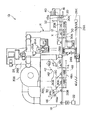
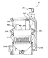
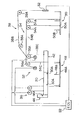
- FIG. 1 is a side view schematically showing a shot blasting apparatus according to an embodiment of the present invention. It is a front view which shows schematically the shot blasting apparatus of FIG. It is a perspective view which shows a part of shot blasting apparatus which concerns on one Embodiment of this invention.
- FIG. 4 is a cross-sectional view corresponding to an enlarged cross section taken along line 4-4 of FIG. It is a side view which shows typically the raising / lowering mechanism in the shot blasting apparatus which concerns on one Embodiment of this invention.
- FIG. 1 shows a schematic configuration of a shot blasting apparatus 10 according to an embodiment of the present invention in a side view
- FIG. 2 shows a schematic configuration of the shot blasting apparatus 10 in a front view
- FIG. 3 is a perspective view showing a part of the shot blasting apparatus 10 and the H-section steel 12 as the object to be processed.
- the H-shaped steel 12 is a long member and includes a web 12A and a flange 12B.
- the H-shaped posture (the posture of the web 12A is a horizontal posture). Is conveyed along the longitudinal direction of the H-shaped steel 12. In such a conveying state of the H-shaped steel 12, the one surface of the web 12A becomes the upper surface 112A directed upward.
- the shot blasting apparatus 10 includes a cabinet 14.
- the inside of the cabinet 14 constitutes a processing chamber that is long in the conveying direction (arrow X direction) of the H-section steel 12.
- the cabinet 14 has a product carry-in part 16 formed on the carry-in side (right side in the figure) and a product carry-out part 18 formed on the carry-out side (left side in the figure).
- a conveying device (conveying means) 20 for conveying the H-section steel 12 is provided.
- a plurality of round bar-shaped conveyor rollers 20 ⁇ / b> B are rotatably supported on a conveyor base 20 ⁇ / b> A provided on both sides in the transport width direction.
- the plurality of conveyor rollers 20B are arranged at appropriate intervals along the conveying direction (arrow X direction) and the length direction of the conveyor roller 20B is orthogonal to the conveying direction to form a conveying path for the H-section steel 12 Yes.
- the motor is connected to a drive motor M (schematically shown on the left side in the drawing) and is rotated by the drive force of the drive motor M. That is, the H-section steel 12 is placed on the conveyor roller 20B and conveyed.
- An electronic control unit (ECU: Electronic Control Unit) (control means or control unit) 22 is connected to the drive motor M.
- the ECU 22 is shown as a schematic block in the drawing.
- projection devices (projection means) 24 ⁇ / b> A and 24 ⁇ / b> B are arranged on both sides of the ceiling portion of the cabinet 14 and on the lower side portions on both sides.
- each of the projection devices 24A and 24B is a centrifugal shot projection device (impeller unit) that accelerates the projection material (shot) with a centrifugal force and projects the projection material in a predetermined direction, but is not limited thereto. Absent.
- the upper projection device 24 ⁇ / b> A is installed on the upper side on both sides of the conveyance path, and projects the projection material to the H-section steel 12 from the obliquely upper side.
- the lower projection device 24 ⁇ / b> B is installed on the lower side on both sides of the conveyance path, and projects the projection material obliquely from the lower side to the H-section steel 12.
- the projection devices 24A and 24B are schematically shown for convenience of explanation, but these projection devices 24A and 24B are shown in the ECU 22 shown in FIG. 1 (not shown in FIG. 3). It is connected to the.
- shot supply devices 28A and 28B are connected to the projection devices 24A and 24B.
- the shot supply devices 28A and 28B are devices that supply the projection material to the projection devices 24A and 24B, and include a gate (not shown) that can be opened and closed at the projection material supply unit.
- the shot supply devices 28A and 28B can variably adjust the supply amount of the projection material to the projection devices 24A and 24B by changing the opening of the gate. Note that the variable supply of the projection material by the shot supply devices 28A and 28B is two steps in the present embodiment, but may be performed in a stepless manner.
- a circulation device 26 is connected to the projection devices 24A and 24B via shot supply devices 28A and 28B.
- the circulation device 26 is a device that conveys the projection material projected by the projection devices 24A and 24B and circulates the projection material to the projection devices 24A and 24B.
- the screw conveyor 26A and the upper and lower devices arranged on both sides on the bottom side of the cabinet 14 are used.
- a bucket elevator 26B extending in the direction is provided.
- the screw conveyor 26A extends with the conveying direction (arrow X direction) of the H-section steel 12 as an axial direction, and a shaft portion is rotatably supported on the cabinet 14 side (not shown).
- This screw conveyor 26A is connected to a drive motor 26C, and is rotated by the driving force of the drive motor 26C, and is provided with symmetrical left and right screw portions capable of transporting the projection material from the left and right sides in the drawing to the center side. It arrange
- the circulation device 26 is provided with one end side of an upper screw conveyor 26D for conveying in the horizontal direction on the upper side of the bucket elevator 26B (see FIG. 1).
- a shot tank 26E for storing a projection material is provided on the lower side.
- the shot tank 26E is connected to shot supply devices 28A and 28B (see FIG. 1).
- a blowing port 30A of an air blower device (spraying means) 30 is disposed downstream of the projection devices 24A and 24B and above the transport passage.
- the air blower device 30 includes a blower fan 30 ⁇ / b> B provided at an upper portion of the cabinet 14.
- the blower fan 30B is operable by a driving force of a driving motor (not shown) and is connected to the duct 30C.
- the lower part side of the duct 30C is a movable part that can be moved up and down, and a nozzle part 130 having a blowing port 30A is formed on the lower end side of the duct 30C.
- the air blower device 30 can spray gas (air) from the spray port 30 ⁇ / b> A toward the upper surface 112 ⁇ / b> A side of the H-section steel 12 by driving the drive motor.
- the air blower device 30 is preferably configured such that the streamline direction of the gas blown to the object to be treated is inclined downward from the downstream in the transport direction toward the upstream in the transport direction. Therefore, in this embodiment, the gas blowing direction of the air blower device 30 is set by the inclination angle of the nozzle portion 130. That is, the blowing of the gas by the air blower device 30 is set so that the stream line direction of the blown gas is inclined downward from the downstream in the transport direction toward the upstream in the transport direction.
- a drive motor (not shown) of the blower fan 30B is connected to the ECU 22 so as to be controllable.
- a transfer mechanism (transfer means) 42 connected to and integrated with the air blower device 30 is disposed on the upstream side of the air blower device 30.
- the transfer mechanism 42 includes a housing portion 142 that is open at a lower portion near the air blower device 30. That is, the lower opening of the housing part 142 faces the conveyance path.
- the housing part 142 schematically shows a cross-sectional shape including a lower opening thereof.
- the housing part 142 is integrally formed with a receiving plate part 42C at a position adjacent to the lower opening on the upstream side of conveyance.
- the receiving plate portion 42 ⁇ / b> C is set at a height position substantially equal to the blowing port 30 ⁇ / b> A of the air blower device 30.
- the transfer mechanism 42 includes a screw conveyor 42A that is close to the upper side of the receiving plate portion 42C.
- the receiving plate portion 42 ⁇ / b> C constitutes a projection material collection accommodating portion provided downstream of the projection devices 24 ⁇ / b> A and 24 ⁇ / b> B in the transport direction and above the transport passage.
- 42 C of this receiving plate part is the projection material which rose with the gas which reflected the upper surface 112A of H-section steel 12 from the H-section steel 12 by the blowing of the gas by the air blower apparatus 30 especially from the upper surface 112A side. ).
- the screw conveyor 42A extends with the conveyance width direction (perpendicular direction with respect to the paper surface of FIG. 1) as the axial direction, and faces the accommodating portion (receiving plate portion) 42C.
- FIG. 4 shows an enlarged sectional view taken along line 4-4 of FIG.
- the screw conveyor 42 ⁇ / b> A is rotatably supported by the brackets 44 on both sides.
- the bracket 44 is connected to a part of the air blower device 30 (see FIG. 1).
- the screw conveyor 42A is connected to the driving motor 42B and rotates by the driving force of the driving motor 42B, and can convey the projection material on the receiving plate portion 42C from the center side in the drawing to the left and right sides (arrows W1 and W2 directions). It has a symmetrical screw part.
- a discharge part 142 that allows the projection material to drop downward is formed on the outer side in the conveyance width direction than the H-section steel 12.
- the discharge portion 142 is disposed above the screw conveyor 26A on the bottom side of the cabinet 14 shown in FIG. Thereby, the transfer mechanism 42 transfers the projection material blown up from the upper surface 112 ⁇ / b> A side of the H-section steel 12 by the gas blowing of the air blower device 30 to the circulation device 26.
- a spray port 46A of a final blower device (further spraying means) 46 is disposed downstream of the air blower device 30 and above the transport passage.
- the spray port 46 ⁇ / b> A is formed on the tip side of the nozzle portion 146 of the final blower device 46.
- the lower side (movable part) of the final blower device 46 can be displaced integrally with the lower side (movable part) of the air blower device 30, and the blowing port 46 ⁇ / b> A of the final blower device 46 is an air blower device. It is set at a position slightly higher than 30 spray ports 30A.
- the final blower device 46 has a structure capable of blowing compressed air (gas) from the blowing port 46A toward the upper surface 112A side of the H-section steel 12.
- the final blower device 46 is preferably configured such that the streamline direction of the gas blown to the object to be treated is inclined downward from the downstream in the transport direction toward the upstream in the transport direction. Therefore, in the present embodiment, the streamline direction of the gas blown out from the blowing port 46A of the final blower device 46 is set so as to be inclined downward from the downstream in the transport direction toward the upstream in the transport direction.
- a height detection sensor 32 (which also serves as a “collision prevention device”) is arranged upstream of the air blower device 30 and the projection devices 24A and 24B in the transport direction. ing.
- the height detection sensor 32 detects the height position in the conveyance state of the object to be processed being conveyed. If the object 12 to be processed is an H-section steel as in this embodiment, the height position that the height detection sensor 32 should detect is the flange upper end position of the H-section steel 12.
- the height detection sensor 32 is connected with a first lifting device (lifting means) 36 via the ECU 22.
- the first lifting device 36 includes a winch, and is moved to a position where the air blower device 30 does not contact the H-section steel 12 (see FIG. 1) according to a command from the ECU 22 according to the detection result by the height detection sensor 32.
- the movable part of the air blower device 30 on the side of the blowing port 30A is raised and lowered, and the movable part of the final blower device 46 is also raised and lowered integrally.
- the height position of the lower end of the height detection sensor 32 is set to be equal to the height position of the lower end of the air blower device 30.
- the height position of the lower end of the height detection sensor 32 may be set to a slightly lower height position than the height position of the lower end of the air blower device 30.
- the height detection sensor 32 and the air blower device 30 are preferably connected by an interlocking mechanism 38.
- the interlocking mechanism 38 includes a wire 38B and a chain 38C wound around a pulley 38A, and connects the height detection sensor 32 and the air blower device 30.
- the air blower device moves the height detection sensor 32 up and down (vertical displacement). It is interlocked with 30 raising / lowering (vertical displacement).
- an end detection sensor 40 is disposed at a position closer to the product carry-in portion 16 on the upstream side of the transport than the projection devices 24A and 24B.
- the end detection sensor 40 is connected to the ECU 22 so as to detect passage of the front and rear ends of the H-section steel 12 and to input a detection signal thereof (the connection method is not shown).
- the ECU 22 Based on the detection result by the end detection sensor 40 and the set speed of the conveyor roller 20B (conveying speed by the conveying device 20), the ECU 22 moves the H-section steel 12 along the conveying direction (arrow X direction) on the conveying path.
- the projection devices 24A and 24B and the air blower device 30 are operated.
- the ECU 22 stops driving of the drive motor M when it is determined based on the detection result by the end detection sensor 40 that the time during which the H-section steel 12 is not present on the transport path has reached a predetermined value or more. The operation of the transfer device 20 is stopped.
- scattering prevention devices 48 and 50 are arranged on the lower side of the conveyance path of the H-section steel 12.
- the anti-scattering devices 48 and 50 include holding brackets 48A and 50A that are horizontally disposed along the conveyance path of the H-section steel 12, and on the holding brackets 48A and 50A along the conveyance direction (arrow X direction).
- a plurality of scattering prevention portions 48B and 50B are provided.
- the scattering prevention members 48B and 50B are made of a material having high elasticity such as resin (so-called “strong waist”), and the lower ends thereof are fixed to the holding brackets 48A and 50A.
- strong waist a material having high elasticity
- the scattering prevention portions 48 ⁇ / b> B and 50 ⁇ / b> B are composed of a plurality of long materials that are self-supporting with flexibility, and are bent in the conveying direction of the H-section steel 12 when the H-section steel 12 passes. Is set to 1 prevents the projection material projected on the lower surface 212A side of the H-shaped steel 12 from scattering along the lower surface 212A side of the H-shaped steel 12.
- the scattering prevention devices 48, 50 are connected to a second lifting device (lifting means) 52. Further, the second lifting device 52 is connected to the height detection sensor 32 via the ECU 22.
- the second lifting and lowering device 52 includes a winch, and the upper ends of the scattering prevention portions 48B and 50B are shown in FIG. 4 according to a command from the ECU 22 according to the detection result by the height detection sensor 32.
- the scattering prevention devices 48 and 50 (see FIG. 5) are moved up and down to a height position in contact with the lower surface 212A.
- the detection result by the height detection sensor 32 that detects the height position of the H-section steel 12 is determined by the raising and lowering of the scattering prevention devices 48 and 50 by the second lifting device 52 and the first lifting device 36. It is used for raising and lowering the air blower device 30.
- the scattering prevention device 48 on the downstream side of the conveyance and the scattering prevention device 50 on the upstream side of the conveyance are connected by a synchronization mechanism 54.
- the synchronization mechanism 54 includes a wire 54B and a chain 54C wound around a pulley 54A, and connects the scattering prevention device 48 and the scattering prevention device 50.
- an H-section steel 12 carried in an H-shaped posture (a posture in which the web surface is lateral) from the product carry-in portion 16 side is an end in the conveying direction of the H-section steel 12 by an end detection sensor 40. Passing of the section (front end and rear end) is detected, and the conveyor roller 20B of the transport device 20 is rotated to be transported in the transport direction (arrow X direction). Based on the detection result by the end detection sensor 40 and the set speed of the conveyor roller 20B (conveying speed by the conveying device 20), the H-section steel 12 exists within a predetermined range in the conveying direction (arrow X direction) on the conveying path.
- projection device 24A, 24B and the air blower apparatus 30 are operated by the instruction
- the projection devices 24A and 24B start operating immediately before the H-section steel 12 arrives at the projection area, and operate immediately after the H-section steel 12 passes through the projection area.
- the air blower device 30 ends and starts operating immediately before the H-section steel 12 arrives at the blower area, and ends immediately after the H-section steel 12 passes through the blower area.
- the H-section steel 12 is projected and polished by the projection material 24A and 24B. Thereby, a part of the projection material remains on the upper surface 112 ⁇ / b> A of the H-section steel 12.
- the air blower device 30 blows gas toward the upper surface 112A side of the H-section steel 12 in such a state. As a result, the projection material on the H-shaped steel 12 is blown off and removed. That is, the projection material is removed without contacting the H-shaped steel 12 with a cleaning member for removing the projection member.
- the blowing of the gas by the air blower device 30 is set so that the streamline direction of the blown gas is inclined downward from the downstream in the transport direction toward the upstream in the transport direction, and thus the upper surface 112A of the H-section steel 12 Gas is blown onto the projection material remaining on the substrate in the direction opposite to the conveying direction. For this reason, the projection material on the upper surface 112A of the H-section steel 12 is efficiently blown away.
- the blown up projection material returns to the upper surface 112A of the H-section steel 12. It can be prevented or suppressed.
- the projection material remains on the H-shaped steel 12 even when the H-shaped steel 12 is blasted (surface treated) while being conveyed in an H-shaped posture. Can be prevented or suppressed.
- the projection material blown up on the receiving plate portion 42C is rotated by the screw conveyor 42A so that both left and right sides (in the directions of arrows W1 and W2) from the axial center of the screw conveyor 42A.
- the screw conveyor 26A at the bottom of the cabinet 14 shown in FIG. Thereby, the projection material blown up from the upper surface 112 ⁇ / b> A side of the H-section steel 12 by the gas blowing of the air blower device 30 is transferred to the circulation device 26.
- the projection material conveyed to the lower side of the bucket elevator 26B by the screw conveyor 26A is conveyed upward by the bucket elevator 26B, and passes through the upper screw conveyor 26D and the shot tank 26E shown in FIG. It is supplied from the shot supply devices 28A and 28B (see FIG. 1) to the projection devices 24A and 24B. That is, the projected projection material is circulated by the circulation device 26 to the projection devices 24A and 24B. Further, since the shot supply devices 28A and 28B shown in FIG. 1 can variably adjust the supply amount of the projection material to the projection devices 24A and 24B by adjusting the opening degree of the gate, the projection devices 24A and 24B Appropriate amount of projection material can be supplied.
- the height in the conveyance state of the H-section steel 12 is detected by the height detection sensor 32 provided on the product carry-in section 16 side.
- the air blower device 30 shown in FIG. 5 is moved up and down by the first lifting device 36 according to the detection result by the height detection sensor 32. For this reason, the air blower device 30 is set to an appropriate height position according to the height of the H-section steel 12 (see FIG. 1), and blows off the projection material on the upper surface 112A (see FIG. 1) of the H-section steel 12.
- the height position of the lower end of the height detection sensor 32 is set to the same height position as the height position of the lower end of the air blower device 30, and the elevation mechanism 32 is moved up and down by the interlocking mechanism 38.
- the air blower 30 is moved up and down. For this reason, if the lower end of the height detection sensor 32 is set at a position where it does not collide with the H-section steel 12 (see FIG. 1), the collision between the air blower device 30 and the H-section steel 12 is avoided.
- the blowing port 46 ⁇ / b> A of the final blower device 46 is disposed downstream of the air blower device 30 and above the transport passage, and the final blower device 46 is Since the gas can be blown toward the upper surface 112A side of the H-shaped steel 12, the projection material on the H-shaped steel 12 cannot be completely removed only by blowing the gas by the air blower device 30, and to some extent Even if the projection material still remains on the H-section steel 12, the remaining projection material can be removed by gas blowing by the final blower device 46.
- the scattering prevention units 48B and 50B of the scattering prevention devices 48 and 50 are disposed below the conveyance path of the H-section steel 12, and the scattering prevention units 48B and 50B are disposed on the lower surface 212A side of the H-section steel 12.
- the projected blasting material is prevented from scattering along the lower surface 212A side of the H-section steel 12 to the outside of the apparatus.
- the scattering prevention portions 48B and 50B are configured by a plurality of self-supporting long materials having flexibility and set so as to bend in the conveying direction (arrow X direction) of the H-section steel 12 when the H-section steel 12 passes.
- the scattering prevention devices 48 and 50 are lifted and lowered by the second lifting and lowering device 52 according to the detection result by the height detection sensor 32. For this reason, the scattering prevention devices 48 and 50 are set at appropriate height positions according to the height of the H-section steel 12 (see FIG. 1).
- the H-section steel 12 shown in FIG. 1 is carried out, and based on the detection result by the end detection sensor 40, it is determined that the time during which the H-section steel 12 does not exist on the conveyance path has reached a predetermined value or more. In this case, the operation of the transport device 20 is stopped when the drive motor M is stopped by a command from the ECU 22.
- the blowing of the gas by the air blower device 30 is set so that the streamline direction of the blown gas is inclined downward toward the upstream side in the transport direction.
- Such a setting is preferable from the viewpoint of efficiently blowing off the projection material on the upper surface 112A of (target object).
- the gas blowing direction by the spraying device is not limited to this. That is, the blowing of the gas by the blowing device may be set so that the streamline direction of the blown gas is downward, or the streamline direction of the blown gas is inclined downward toward the downstream in the transport direction. You may set so that it may become a direction.
- the blowing direction of the gas by the air blower apparatus 30 is set with the inclination angle of the nozzle part 130 of the air blower apparatus 30, the setting of the blowing direction of the gas by the blowing apparatus is, for example, spraying of the blowing apparatus
- a deflecting plate may be provided adjacent to the mouth and may be set by another structure such as setting by the posture of the deflecting plate.
- the receiving plate part 42C (accommodating part) and the screw conveyor 42A for receiving and accommodating the projection material blown up from the upper surface 112A side of the H-section steel 12 by the gas blowing by the air blower device 30 are provided. It has been. Such a configuration is more preferable from the viewpoint of preventing or suppressing the blown-up projection material from returning to the upper surface 112A of the H-section steel 12 (object to be processed), but a receiving plate portion 42C and a screw conveyor 42A are provided. It is also possible to adopt a configuration without this.
- the transfer mechanism 42 has transferred the projection material blown up from the upper surface 112A side of the H-section steel 12 by the blowing of the gas of the air blower apparatus 30 to the circulation apparatus 26, and H-section steel 12 (to-be-processed)
- a configuration is more preferable from the viewpoint of circulating and using the projection material blown up from the upper surface side of the target), but a configuration without the transfer mechanism 42 is also possible.
- the shot blasting apparatus 10 (surface treatment apparatus) is preferably configured to include the circulation device 26, but a surface treatment apparatus that does not include the circulation device may also be realized.
- the first lifting device 36 shown in FIG. 5 lifts and lowers the movable portion on the side of the air outlet 30A of the air blower device 30, the movable portion of the final blower device 46, and the height detection sensor 32.
- the second lifting and lowering device 52 lifts and lowers the scattering prevention devices 48 and 50.
- each part lifted and lowered by the first and second lifting devices 36 and 52 may be manually lifted and lowered instead of the first and second lifting devices 36 and 52.
- the 1st raising / lowering apparatus 36 raises / lowers the movable part by the side of the blowing port 30A of the air blower apparatus 30 automatically according to the instruction
- FIG. instead, for example, the operator manually inputs data related to the detection result by the height detection sensor 32 to a terminal connected to the ECU 22, and the ECU 22 moves the movable part on the spray port side of the spray device based on the input data. It is good also as a structure which raises / lowers 1st raising / lowering apparatus 36 or another raising / lowering means.
- ECU22 is based on the detection result by a height detection sensor, for example, ECU22 is the air blower apparatus 30 and H-section steel. 1 is stopped, the drive motor M of the conveyor roller 20B shown in FIG. 1 is stopped, and the operator is prompted to reset the height by the first lifting device 36 (see FIG. 5). It may be configured to emit an audible or visual warning (for example, an alarm sound or display display).
- the H-section steel 12 is a conveyance direction (arrow X direction) on a conveyance path.
- the ECU 22 activates the projection devices 24A and 24B and the air blower device 30 when the ECU 22 determines that it is within the predetermined range of, for example, an end detection sensor that detects an end of the object to be processed in the transport direction.
- the ECU 22 may activate the projection device and the spray device when the ECU 22 determines that the projection device and the spray device are present.
- the final blower device (further spraying means) 46 from the viewpoint of more effectively preventing or suppressing the projection material from remaining on the object to be treated (H-shaped steel 12 in the above embodiment). Is preferably provided. However, it is also possible to constitute an embodiment in which no final blower device is provided.
- the scattering prevention devices 48 and 50 may be provided as described above. preferable. However, it is also possible to constitute an embodiment in which no scattering prevention device is provided.
- the scattering prevention portions 48B and 50B are configured by a plurality of self-supporting long materials having flexibility, and are set to bend in the transport direction of the processing target when passing the processing target. ing.
- This configuration is preferable from the viewpoint of corresponding to the H-section steel 12 having various widths, for example.
- the scattering prevention member may be a shield that is disposed at a position that blocks a previously assumed scattering locus.
- the second lifting and lowering device 52 lifts and lowers the scattering prevention devices 48 and 50.
- the operator manually inputs data related to the detection result by the height detection sensor 32 to a terminal connected to the ECU 22, and the ECU 22 sets the scattering prevention device as the second lifting device based on the input data. It is good also as a structure which raises / lowers 52 or another raising / lowering means.
- the operation of the transport device 20 is stopped by stopping the drive, and such a configuration is preferable from the viewpoint of appropriately controlling the operation of the transport device 20.
- the control unit determines that the time during which the object to be processed is not present on the conveyance path has reached a predetermined value or more, the operation of the conveyance device is performed for the operator. For example, an audible or visual warning (for example, an alarm sound or a display display) may be generated.
- the shot supply devices 28A and 28B capable of variably changing the supply amount of the projection material to the projection devices 24A and 24B as described above.
- a configuration to be used is preferable.
- variable supply devices 28A and 28B it is possible to use a shot supply device in which the supply amount of the projection material to the projection device is constant.
- the surface treatment apparatus is made into the shot blasting apparatus 10, the surface treatment apparatus of this invention is not limited to this, For example, a shot peening method and other projection materials It is good also as a surface treatment apparatus applied to the surface treatment method using.
- the object to be processed is an H-shaped steel having an H-shaped section
- the object to be processed is, for example, a U-shaped steel having a U-shaped section, a J-shaped steel having a J-shaped section, and others. It is good also as a processing target.
- the surface treatment apparatus of the present invention can be applied to, for example, a surface treatment in the case where U-shaped steel is conveyed in a U-shape or when J-shaped steel is conveyed in a J-shape.
Landscapes
- Engineering & Computer Science (AREA)
- Mechanical Engineering (AREA)
- Cleaning In General (AREA)
Abstract
Description
従って、このような従来装置では、H形鋼の表面処理をする場合、投射後にH形鋼上に投射材が残留しないように、表面処理後のH形鋼をI字姿勢(ウェブ面が縦の姿勢)で搬送させる必要がある。しかし、このような姿勢での搬送は安定性に欠けることとなる。一方、H形鋼をH字姿勢で搬送させると、上述のようにH形鋼上に投射材が残留してしまう。
被処理対象を搬送する搬送通路を形成し、その搬送通路に沿って被処理対象を搬送方向へ搬送する搬送手段と、
前記搬送されてくる被処理対象に対して投射材を投射して表面処理する投射手段と、
前記投射手段よりも前記搬送方向の下流における前記搬送通路の上方から、被処理対象の上面へ向けて気体を吹き付ける吹付手段と、を備える。
これにより被処理対象上に投射材が残留するのを防止又は抑制することができる。
移送手段により移送された投射材を投射手段へ循環させる循環手段と、を更に備えてもよい。
この場合、収容部内に受け入れられた投射材も循環利用するために、収容部を移送手段に連通させることが好ましい。
この更なる吹付手段は、被処理対象へ吹き付けられる気体の流線方向が、搬送方向下流から搬送方向の上流へ向かって下方へ傾斜するように構成することが好ましい。
明細書の一部に含まれ、それを構成する添付図面は、本発明の好ましい実施形態を概略的に示し、上述の一般的説明および以下の好ましい実施形態の詳細な説明と共に、本発明の要旨を説明するのに役立つ。
図3に示されるように、上側の投射装置24Aは、搬送通路の両サイド側の上方側に設置され、H形鋼12に対して投射材を斜め上方側から投射する。また、下側の投射装置24Bは、搬送通路の両サイド側の下方側に設置され、H形鋼12に対して投射材を斜め下方側から投射する。なお、図3では、説明の便宜のために投射装置24A、24Bを模式化して示してあるが、これらの投射装置24A、24Bは、図1に示されるECU22(図3には図示せず)に接続されている。
本実施形態では、H形鋼12の高さ位置を検出する高さ検出センサ32による検出結果が、第2の昇降装置52による飛散阻止装置48、50の昇降と、第1の昇降装置36によるエアブロア装置30の昇降とに用いられている。
それらに対して本実施形態に係るショットブラスト10では、このような不都合は生じない。また、本実施形態に係るショットブラスト装置10によれば、投射後にH形鋼12上の投射材を作業者が手作業で除去する作業も不要又は極めて短時間にすることができる。
12 H形鋼(被処理対象)
20 搬送装置
22 ECU(制御手段)
24A,24B 投射装置(投射手段)
26 循環装置(循環手段)
30 エアブロア装置(吹付手段)
30A 吹付口
32 高さ検出センサ
36 第1の昇降装置(昇降手段)
38 連動機構
40 端部検出センサ
42 移送機構(移送手段)
42A スクリュウコンベヤ
42C 受板部(収容部)
46 ファイナルブロア装置(更なる吹付手段)
46A 吹付口
48,50 飛散阻止装置(飛散防止手段)
48B,50B 飛散阻止部材
52 第2の昇降装置(更なる昇降手段)
Claims (20)
- 被処理対象を投射材により表面処理する装置であって、
被処理対象を搬送する搬送通路を形成し、その搬送通路に沿って被処理対象を搬送方向へ搬送する搬送手段と、
前記搬送されてくる被処理対象に対して投射材を投射して表面処理する投射手段と、
前記投射手段よりも前記搬送方向の下流における前記搬送通路の上方から、被処理対象の上面へ向けて気体を吹き付ける吹付手段と、
を備える表面処理装置。 - 前記吹付手段は、被処理対象へ吹き付けられる気体の流線方向が、前記搬送方向下流から前記搬送方向の上流へ向かって下方へ傾斜するように構成されている請求項1記載の表面処理装置。
- 前記投射手段よりも前記搬送方向下流における前記搬送通路の上方に、前記吹付手段による気体の吹き付けによって被処理対象から吹き上げられた投射材を受け入れる収容部が設けられている請求項1又は2に記載の表面処理装置。
- 前記投射された投射材を移送する移送手段と、
前記移送手段により移送された投射材を投射手段へ循環させる循環手段と、
を更に備える請求項1又は2に記載の表面処理装置。 - 前記投射された投射材を移送する移送手段と、
前記移送手段により移送された投射材を投射手段へ循環させる循環手段と、
を更に備える請求項3に記載の表面処理装置。 - 前記収容部は前記移送手段に一体的に設けられている請求項4記載の表面処理装置。
- 前記収容部は前記移送手段に一体的に設けられている請求項5記載の表面処理装置。
- 前記吹付手段よりも前記搬送方向上流に配置され、前記搬送されてくる被処理対象の高さを検出する高さ検出センサと、
前記記高さ検出センサによる検出結果に応じて前記吹付手段を昇降させる昇降手段と、を更に備える請求項1又は2に記載の表面処理装置。 - 前記吹付手段よりも前記搬送方向上流に配置され、前記搬送されてくる被処理対象の高さを検出する高さ検出センサと、
前記記高さ検出センサによる検出結果に応じて前記吹付手段を昇降させる昇降手段と、を更に備える請求項3に記載の表面処理装置。 - 前記高さ検出センサの下端の高さ位置が、前記吹付手段の下端の高さ位置に対して等高位置又はより低い高さ位置に設定されると共に、
前記高さ検出センサの昇降を前記吹付手段の昇降に連動させる連動機構を更に備える請求項6記載の表面処理装置。 - 前記投射手段よりも前記搬送方向上流に配置され、前記搬送されてくる被処理対象の先端部及び後端部の通過を検出する端部検出センサと、
前記端部検出センサによる検出結果と、前記搬送手段による被処理対象の搬送速度とに基づいて、被処理対象が搬送通路上で前記搬送方向に沿った所定範囲内に存在すると判断した場合に前記投射手段及び前記吹付手段を起動させる制御手段と、
を更に備える請求項1又は2に記載の表面処理装置。 - 前記投射手段よりも前記搬送方向上流に配置され、前記搬送されてくる被処理対象の先端部及び後端部の通過を検出する端部検出センサと、
前記端部検出センサによる検出結果と、前記搬送手段による被処理対象の搬送速度とに基づいて、被処理対象が搬送通路上で前記搬送方向に沿った所定範囲内に存在すると判断した場合に前記投射手段及び前記吹付手段を起動させる制御手段と、
を更に備える請求項1又は2に記載の表面処理装置。
- 前記吹付手段よりも前記搬送方向下流における前記搬送通路の上方から、被処理対象の上面へ向けて気体を吹き付ける更なる吹付手段を更に備える請求項1又は2に記載の表面処理装置。
- 前記吹付手段よりも前記搬送方向下流における前記搬送通路の上方から、被処理対象の上面へ向けて気体を吹き付ける更なる吹付手段を更に備える請求項3に記載の表面処理装置。
- 前記更なる吹付手段は、被処理対象へ吹き付けられる気体の流線方向が、前記搬送方向下流から前記搬送方向の上流へ向かって下方へ傾斜するように構成されている請求項9記載の表面処理装置。
- 前記被処理対象の搬送通路の下方に配置されて前記被処理対象へ投射された投射材が前記被処理対象の下面側を伝って飛散するのを阻止する飛散阻止部材を有する飛散阻止手段を更に備える請求項16に記載の表面処理装置。
- 前記飛散阻止部材は、自立した複数の長尺部材を含み、その各々の長尺部材は可撓性を有しており、被処理対象の通過時に前記搬送方向へ撓むようにされている請求項1又は2記載の表面処理装置。
- 前記吹付手段よりも前記搬送方向上流に配置され、前記搬送されてくる被処理対象の高さを検出する高さ検出センサと、
前記高さ検出センサによる検出結果に応じて前記飛散阻止手段を昇降させる更なる昇降手段と、
を更に備える請求項16又は17に記載の表面処理装置。 - 前記投射手段よりも前記搬送方向上流に配置され、前記搬送されてくる被処理対象の先端部及び後端部の通過を検出する端部検出センサと、
前記端部検出センサ部による検出結果に基づいて、前記搬送通路上に被処理対象が存在しない時間が所定値以上に達したと判断した場合に前記搬送手段の作動を停止させる制御手段を更に備える請求項1又は2に記載の表面処理装置。 - 前記投射手段へ投射材を可変な供給量で供給する可変供給手段を更に備える請求項1又は2に記載の表面処理装置。
Priority Applications (3)
| Application Number | Priority Date | Filing Date | Title |
|---|---|---|---|
| CN201180002270.0A CN102448670B (zh) | 2010-07-29 | 2011-03-01 | 表面处理装置 |
| US13/504,714 US9156132B2 (en) | 2010-07-29 | 2011-03-01 | Surface treatment machine |
| KR1020127026539A KR101820441B1 (ko) | 2010-07-29 | 2011-03-01 | 표면 처리 장치 |
Applications Claiming Priority (2)
| Application Number | Priority Date | Filing Date | Title |
|---|---|---|---|
| JP2010-171022 | 2010-07-29 | ||
| JP2010171022A JP5471944B2 (ja) | 2010-07-29 | 2010-07-29 | 表面処理装置 |
Publications (1)
| Publication Number | Publication Date |
|---|---|
| WO2012014514A1 true WO2012014514A1 (ja) | 2012-02-02 |
Family
ID=45529738
Family Applications (1)
| Application Number | Title | Priority Date | Filing Date |
|---|---|---|---|
| PCT/JP2011/054626 Ceased WO2012014514A1 (ja) | 2010-07-29 | 2011-03-01 | 表面処理装置 |
Country Status (5)
| Country | Link |
|---|---|
| US (1) | US9156132B2 (ja) |
| JP (1) | JP5471944B2 (ja) |
| KR (1) | KR101820441B1 (ja) |
| CN (1) | CN102448670B (ja) |
| WO (1) | WO2012014514A1 (ja) |
Families Citing this family (10)
| Publication number | Priority date | Publication date | Assignee | Title |
|---|---|---|---|---|
| JP6327150B2 (ja) * | 2013-01-30 | 2018-05-23 | 新東工業株式会社 | ショット処理装置 |
| CN104802094A (zh) * | 2015-04-20 | 2015-07-29 | 骏马石油装备制造有限公司 | 一种连续辊道通过式抛丸设备 |
| CN105583739A (zh) * | 2015-12-20 | 2016-05-18 | 安徽伟宏钢结构集团股份有限公司 | 一种抛丸除锈自动化控制方法 |
| JP7154178B2 (ja) * | 2019-03-29 | 2022-10-17 | 株式会社レプトリノ | 力覚センサ及び起歪体 |
| KR102209978B1 (ko) * | 2019-06-13 | 2021-01-29 | 이세창 | 판재용 쇼트 블라스트 장치 |
| KR102173958B1 (ko) * | 2019-12-05 | 2020-11-13 | 주식회사 태산정공 | 이송장치를 이용한 폼용 쇼트 블라스트 장치 |
| JP7272308B2 (ja) * | 2020-03-31 | 2023-05-12 | 新東工業株式会社 | ショット処理装置およびショット処理方法 |
| JP7453858B2 (ja) * | 2020-06-18 | 2024-03-21 | サンコール株式会社 | ショットピーニング装置 |
| CN113319745A (zh) * | 2021-07-02 | 2021-08-31 | 泰州市大润机械有限公司 | 一种低提升分离循环系统 |
| JP7722109B2 (ja) * | 2021-09-30 | 2025-08-13 | 新東工業株式会社 | ショットブラスト装置、検査方法、検査プログラム |
Citations (6)
| Publication number | Priority date | Publication date | Assignee | Title |
|---|---|---|---|---|
| JPS55156855U (ja) * | 1979-04-23 | 1980-11-11 | ||
| JPS5694264U (ja) * | 1979-12-21 | 1981-07-27 | ||
| JPS59116156U (ja) * | 1983-01-26 | 1984-08-06 | 日本鋼管株式会社 | 鋼板上研掃材のクリ−ナ−装置 |
| JPH04256578A (ja) * | 1991-02-12 | 1992-09-11 | Kobe Steel Ltd | ショット粒吹き落し装置の昇降制御方法 |
| JPH091460A (ja) * | 1995-06-19 | 1997-01-07 | Ito Kiko Kk | ショット除去装置 |
| JP2000176840A (ja) * | 1998-12-17 | 2000-06-27 | Tomoe Corp | ブラスト装置 |
Family Cites Families (15)
| Publication number | Priority date | Publication date | Assignee | Title |
|---|---|---|---|---|
| US2073184A (en) * | 1935-11-11 | 1937-03-09 | Howard V Schweitzer | Apparatus for cleaning articles of ceramic materials |
| US3031802A (en) * | 1960-11-29 | 1962-05-01 | Bell Intercontinental Corp | Blast machine sealing means |
| US3824738A (en) * | 1972-11-01 | 1974-07-23 | W Hall | Pipe cleaning apparatus |
| JPH064283Y2 (ja) * | 1987-07-07 | 1994-02-02 | 大和製衡株式会社 | 組合せ秤の作業指示・監視システム |
| JP2549137B2 (ja) | 1988-01-30 | 1996-10-30 | 新東工業株式会社 | ショットブラスト装置 |
| US5107629A (en) * | 1989-11-09 | 1992-04-28 | The Celotex Corporation | Texturing of acoustical mineral fiberboard with wheel blast machine |
| FR2697769B1 (fr) * | 1992-11-10 | 1995-01-13 | Buchmann Optical Eng | Machine automatique pour meuler et biseauter les verres ophtalmiques. |
| CN2181368Y (zh) | 1993-07-15 | 1994-11-02 | 青岛铸造机械厂 | 辊道连续抛丸清理装置 |
| JP2001179635A (ja) * | 1999-12-27 | 2001-07-03 | Bridgestone Corp | ブラスト装置 |
| AU2001234127A1 (en) * | 2000-02-22 | 2001-09-03 | Hoya Corporation | Lens layout block device |
| JP2003326461A (ja) * | 2002-03-04 | 2003-11-18 | Jfe Steel Kk | 金属板の表面処理設備及び金属板の製造方法 |
| US6688458B2 (en) * | 2001-10-09 | 2004-02-10 | Speedline Technologies, Inc. | System and method for controlling a conveyor system configuration to accommodate different size substrates |
| JP2003340698A (ja) * | 2002-05-30 | 2003-12-02 | Hoya Corp | レンズ加工装置及びレンズ加工方法 |
| JP5218228B2 (ja) * | 2008-04-23 | 2013-06-26 | 新東工業株式会社 | 搬送装置及びブラスト加工装置 |
| CN101288946B (zh) * | 2008-06-04 | 2010-06-09 | 沈阳飞机工业(集团)有限公司 | 喷丸机 |
-
2010
- 2010-07-29 JP JP2010171022A patent/JP5471944B2/ja active Active
-
2011
- 2011-03-01 US US13/504,714 patent/US9156132B2/en active Active
- 2011-03-01 CN CN201180002270.0A patent/CN102448670B/zh active Active
- 2011-03-01 WO PCT/JP2011/054626 patent/WO2012014514A1/ja not_active Ceased
- 2011-03-01 KR KR1020127026539A patent/KR101820441B1/ko active Active
Patent Citations (6)
| Publication number | Priority date | Publication date | Assignee | Title |
|---|---|---|---|---|
| JPS55156855U (ja) * | 1979-04-23 | 1980-11-11 | ||
| JPS5694264U (ja) * | 1979-12-21 | 1981-07-27 | ||
| JPS59116156U (ja) * | 1983-01-26 | 1984-08-06 | 日本鋼管株式会社 | 鋼板上研掃材のクリ−ナ−装置 |
| JPH04256578A (ja) * | 1991-02-12 | 1992-09-11 | Kobe Steel Ltd | ショット粒吹き落し装置の昇降制御方法 |
| JPH091460A (ja) * | 1995-06-19 | 1997-01-07 | Ito Kiko Kk | ショット除去装置 |
| JP2000176840A (ja) * | 1998-12-17 | 2000-06-27 | Tomoe Corp | ブラスト装置 |
Also Published As
| Publication number | Publication date |
|---|---|
| CN102448670A (zh) | 2012-05-09 |
| CN102448670B (zh) | 2015-07-15 |
| KR20130092381A (ko) | 2013-08-20 |
| JP2012030313A (ja) | 2012-02-16 |
| US9156132B2 (en) | 2015-10-13 |
| KR101820441B1 (ko) | 2018-01-22 |
| US20130115853A1 (en) | 2013-05-09 |
| JP5471944B2 (ja) | 2014-04-16 |
Similar Documents
| Publication | Publication Date | Title |
|---|---|---|
| WO2012014514A1 (ja) | 表面処理装置 | |
| CN109701797B (zh) | 预涂底漆生产线 | |
| JP5447530B2 (ja) | 鋼材のショットブラスト装置 | |
| CN111405964B (zh) | 喷丸处理装置以及喷丸处理方法 | |
| KR100646754B1 (ko) | 석재의 표면가공을 위한 쇼트 블라스트 장치 | |
| CN104321165B (zh) | 喷丸处理装置 | |
| JP2009154278A (ja) | ショットブラスト設備 | |
| KR101804475B1 (ko) | 압연강용 연마 세정 설비 | |
| JP7753665B2 (ja) | ブラスト加工装置 | |
| KR200366331Y1 (ko) | 석재의 표면가공을 위한 쇼트 블라스트 장치 | |
| JP7272308B2 (ja) | ショット処理装置およびショット処理方法 | |
| JP5655864B2 (ja) | ショット処理装置 | |
| TWI637815B (zh) | 珠擊處理裝置 | |
| TW202529956A (zh) | 具旋轉式噴擊機構的噴擊系統 | |
| TW202529957A (zh) | 能調整板材及噴擊角度的噴擊系統 | |
| KR20050091478A (ko) | 에프론 쇼트기의 효율적 연마재 투사방법 |
Legal Events
| Date | Code | Title | Description |
|---|---|---|---|
| WWE | Wipo information: entry into national phase |
Ref document number: 201180002270.0 Country of ref document: CN |
|
| 121 | Ep: the epo has been informed by wipo that ep was designated in this application |
Ref document number: 11812110 Country of ref document: EP Kind code of ref document: A1 |
|
| WWE | Wipo information: entry into national phase |
Ref document number: 13504714 Country of ref document: US |
|
| WWE | Wipo information: entry into national phase |
Ref document number: 2488/KOLNP/2012 Country of ref document: IN |
|
| ENP | Entry into the national phase |
Ref document number: 20127026539 Country of ref document: KR Kind code of ref document: A |
|
| NENP | Non-entry into the national phase |
Ref country code: DE |
|
| WWE | Wipo information: entry into national phase |
Ref document number: 1201005717 Country of ref document: TH |
|
| 122 | Ep: pct application non-entry in european phase |
Ref document number: 11812110 Country of ref document: EP Kind code of ref document: A1 |