WO2012011406A1 - 絞り位置測定方法、絞り位置測定装置、絞り位置決め方法及び絞り位置決め装置 - Google Patents
絞り位置測定方法、絞り位置測定装置、絞り位置決め方法及び絞り位置決め装置 Download PDFInfo
- Publication number
- WO2012011406A1 WO2012011406A1 PCT/JP2011/065835 JP2011065835W WO2012011406A1 WO 2012011406 A1 WO2012011406 A1 WO 2012011406A1 JP 2011065835 W JP2011065835 W JP 2011065835W WO 2012011406 A1 WO2012011406 A1 WO 2012011406A1
- Authority
- WO
- WIPO (PCT)
- Prior art keywords
- diaphragm
- lens
- optical
- aperture
- lens unit
- Prior art date
- Legal status (The legal status is an assumption and is not a legal conclusion. Google has not performed a legal analysis and makes no representation as to the accuracy of the status listed.)
- Ceased
Links
Images





Classifications
-
- G—PHYSICS
- G01—MEASURING; TESTING
- G01B—MEASURING LENGTH, THICKNESS OR SIMILAR LINEAR DIMENSIONS; MEASURING ANGLES; MEASURING AREAS; MEASURING IRREGULARITIES OF SURFACES OR CONTOURS
- G01B11/00—Measuring arrangements characterised by the use of optical techniques
- G01B11/14—Measuring arrangements characterised by the use of optical techniques for measuring distance or clearance between spaced objects or spaced apertures
-
- G—PHYSICS
- G01—MEASURING; TESTING
- G01M—TESTING STATIC OR DYNAMIC BALANCE OF MACHINES OR STRUCTURES; TESTING OF STRUCTURES OR APPARATUS, NOT OTHERWISE PROVIDED FOR
- G01M11/00—Testing of optical apparatus; Testing structures by optical methods not otherwise provided for
-
- G—PHYSICS
- G01—MEASURING; TESTING
- G01B—MEASURING LENGTH, THICKNESS OR SIMILAR LINEAR DIMENSIONS; MEASURING ANGLES; MEASURING AREAS; MEASURING IRREGULARITIES OF SURFACES OR CONTOURS
- G01B11/00—Measuring arrangements characterised by the use of optical techniques
- G01B11/002—Measuring arrangements characterised by the use of optical techniques for measuring two or more coordinates
-
- G—PHYSICS
- G02—OPTICS
- G02B—OPTICAL ELEMENTS, SYSTEMS OR APPARATUS
- G02B7/00—Mountings, adjusting means, or light-tight connections, for optical elements
- G02B7/003—Alignment of optical elements
Definitions
- the present invention relates to an aperture position measuring method, an aperture position measuring apparatus, and an aperture positioning method suitable for an imaging apparatus using a solid-state imaging device such as a CCD (Charged Coupled Device) type image sensor or a CMOS (Complementary Metal Oxide Semiconductor) type image sensor. And an aperture positioning device.
- a solid-state imaging device such as a CCD (Charged Coupled Device) type image sensor or a CMOS (Complementary Metal Oxide Semiconductor) type image sensor.
- CMOS Complementary Metal Oxide Semiconductor
- an optical diaphragm is attached in order to block the incidence of unnecessary light.
- the lens optical axis and the center of the optical aperture are provided by attaching a lens and an optical aperture to the lens frame by attaching an attachment part designed in advance so that the lens optical axis and the optical aperture center substantially coincide with each other. Is almost matched. Even with such a conventional positioning method, the optical axis and the center of the optical aperture can be brought close to each other with a certain degree of accuracy, so that there has been no particular problem in the conventional imaging apparatus in which the number of pixels of the solid-state imaging device is relatively small.
- Patent Document 1 discloses a lens measuring apparatus that performs light irradiation toward a diaphragm and obtains spectral characteristic data for each diaphragm value.
- Patent Document 1 does not describe any method for measuring the amount of eccentricity between the lens optical axis and the center of the optical aperture from the above viewpoint, or assembling so as to eliminate the deviation.
- As a method of measuring the eccentricity for example, it is conceivable to calculate the virtual optical axis from the lens outer diameter or the lens barrel outer diameter and measure the eccentricity with the measured optical aperture center.
- an object of the present invention is to provide a diaphragm position measuring method and a diaphragm position measuring apparatus that can accurately measure the amount of deviation between the center of the optical diaphragm and the optical axis. It is another object of the present invention to provide a diaphragm positioning method and a diaphragm positioning device capable of accurately arranging an optical diaphragm in a lens unit.
- the diaphragm position measuring method wherein the optical diaphragm position is measured in a lens unit having an optical diaphragm, a lens, and a lens frame that holds the optical diaphragm and the lens. Entering parallel light parallel to the optical axis of the lens into the lens of the lens unit to form a focused spot; Detecting the position of the focused spot; Detecting a center position of the optical aperture; And a step of obtaining a deviation amount between the position of the focused spot and the center position of the optical aperture.
- the present inventor utilizes the fact that when collimated light parallel to the optical axis is incident on the lens, a condensing spot is formed at a predetermined position on the optical axis (for example, an imaging surface of an imaging device used together with the lens unit).
- the present inventors have found that the position of the optical axis serving as a reference for positioning the optical aperture can be accurately estimated. That is, if collimated light is incident on the lens of the lens unit to form a focused spot and the position of the focused spot is detected, this can be used as a reference point for positioning the optical aperture. Thereby, the amount of deviation between the position of the condensing spot and the center position of the optical diaphragm obtained separately can be obtained, and the lens unit can be effectively inspected using the result. According to the present invention, it is possible to detect the shift amount of the center position of the optical diaphragm within an error of ⁇ 3 ⁇ m.
- the diaphragm position measuring method according to claim 2 is the diaphragm position measuring method according to claim 1, wherein the step of detecting the center position of the optical diaphragm geometrically determines the center position from the inner diameter shape of the optical diaphragm. It is characterized by seeking. Since the shape of the optical diaphragm is generally circular, it can be obtained geometrically and accurately from its inner diameter. For example, if two perpendicular bisectors in a line segment connecting any two points on the inner diameter (excluding the diameter) intersect each other and draw two, the intersection point becomes the center of the circle.
- the center position of the target aperture may be set.
- the method of obtaining is not limited to this method, and for example, the method described in JP-T-2007-524805 may be used.
- the aperture position measuring device is an apparatus for measuring the position of the optical aperture in a lens unit including an optical aperture, a lens, and a lens frame that holds the optical aperture and the lens. At least a part of which is a transmissive part capable of transmitting light, and a support base that supports the lens unit by overlapping the transmissive part; A light irradiation device for irradiating parallel light parallel to the lens optical axis of the lens unit toward the lens unit; First detection means for detecting a position of a focused spot formed when the parallel light passes through the lens of the lens unit; Second detection means for detecting a center position of the optical diaphragm; And calculating means for obtaining a deviation amount between the detected position of the focused spot and the center position of the optical aperture.
- the optical aperture In order to position the optical aperture, parallel light is incident on the lens of the lens unit supported by the support base to form a condensing spot, and the position of the condensing spot is detected by the first detecting means. Can be used as a reference point. According to the present invention, the amount of deviation between the position of the focused spot and the center position of the optical diaphragm obtained by the second detecting means can be obtained by the computing means, and the result is used to inspect the lens unit. Can be performed effectively. According to the present invention, it is possible to detect the shift amount of the center position of the optical diaphragm within an error of ⁇ 3 ⁇ m.
- a diaphragm position measuring apparatus is the diaphragm position measuring apparatus according to the third aspect, wherein the first detection means and / or the second detection means and the support base are arranged to emit the parallel light. And a Z-direction moving stage that is moved relative to the Z direction. Thereby, it is possible to focus on the condensing spot condensed by the lens.
- a diaphragm position measuring device is the diaphragm position measuring device according to the third or fourth aspect, wherein the first detecting means and / or the second detecting means and the support base are connected to the parallel light.
- An XY direction moving stage that is relatively moved in a direction orthogonal to the emission direction, and a movement amount detecting means that detects a movement amount of the XY direction moving stage.
- the first detection unit or the second detection unit and the support base are moved relative to each other in a direction orthogonal to the parallel light emission direction, thereby being condensed by the lens.
- a condensing spot can be captured, and the center position of the optical aperture can be detected.
- the movement amount detecting means detects the movement amount of the XY-direction moving stage, whereby the collection point is detected.
- the coordinates of the light spot and the center position of the optical aperture can be detected.
- a diaphragm position measuring apparatus is the diaphragm position measuring apparatus according to any one of the third to fifth aspects, wherein the light irradiating apparatus and the support base are relative to each other in the emission direction of the parallel light. It is characterized by having a tilt stage that tilts automatically. Thereby, the parallel light emitted from the light source can be incident along the optical axis of the lens.
- a diaphragm position measuring device is the diaphragm position measuring device according to the sixth aspect, further comprising an inclination detecting means for detecting a relative inclination between the parallel light and the support base. .
- an inclination detecting means for detecting a relative inclination between the parallel light and the support base.
- the diaphragm position measuring device is the diaphragm position measuring device according to any one of claims 3 to 7, wherein a light reducing member is inserted between the first detection means and the support base.
- a diaphragm position measuring device is the diaphragm position measuring device according to any one of the third to eighth aspects, wherein the first detecting means also serves as the second detecting means.
- the first detecting means also serves as the second detecting means.
- a microscope can be used in common as the first detection means and the second detection means.
- the aperture positioning method wherein the optical aperture is positioned relative to a lens unit having a lens and a lens frame that holds the lens. Incident parallel light parallel to the optical axis of the lens on the lens of the lens unit to form a focused spot; Holding the optical diaphragm so as to temporarily determine the lens unit; Detecting a center position of the optical aperture; Displacing the optical aperture so that the center position of the optical aperture matches the position of the focused spot; Fixing the optical diaphragm to the lens unit when the center position of the optical diaphragm matches the position of the condensing spot.
- the position of the optical diaphragm is accurately positioned by displacing the optical diaphragm so that the center position of the optical diaphragm that is provisionally determined matches the position of the focused spot, and then fixing it.
- Lens unit can be obtained.
- the optical aperture can be assembled within an error of ⁇ 3 ⁇ m with respect to the optical axis.
- the diaphragm positioning method according to claim 11 is the diaphragm positioning method according to claim 10, wherein the step of detecting the center position of the optical diaphragm obtains the center position geometrically from the inner diameter shape of the optical diaphragm. It is characterized by.
- An aperture stop positioning apparatus wherein the optical aperture is positioned relative to a lens unit having a lens and a lens frame that holds the lens. At least a part is made of a material that can transmit light, and a support base that supports the lens unit; A holding member that holds the optical diaphragm so as to temporarily determine the lens unit; A light irradiation device for irradiating parallel light parallel to the lens optical axis of the lens unit toward the lens unit; First detection means for detecting a position of a focused spot formed when the parallel light passes through the lens of the lens unit; Second detection means for detecting a center position of the optical diaphragm; And a driving device for displacing the holding member together with the optical diaphragm so that a deviation amount between the detected position of the focused spot and the center position of the optical diaphragm is small.
- the driving device displaces the optical diaphragm so that the center position of the optical diaphragm detected by the second detection means approaches the detected condensing spot position.
- a lens unit in which the position of the optical aperture is accurately positioned can be obtained by fixing after matching.
- the optical aperture can be assembled within an error of ⁇ 3 ⁇ m with respect to the optical axis.
- a diaphragm positioning device is the diaphragm positioning device according to the twelfth aspect, in which the first detection unit or the second detection unit and the support base are relatively arranged in an emission direction of the parallel light. It has a Z-direction moving stage to be moved. Thereby, it is possible to focus on the condensing spot condensed by the lens.
- a diaphragm positioning device is the diaphragm positioning device according to the twelfth or thirteenth aspect, wherein the first detection means or the second detection means and the support base are orthogonal to the parallel light emission direction. And an XY direction moving stage that moves relative to the moving direction, and a movement amount detecting means that detects a moving amount of the XY direction moving stage. Capturing the condensing spot condensed by the lens by moving the first detection means and the support base in a direction orthogonal to the parallel light emission direction by the XY direction moving stage.
- the center position of the optical aperture can be detected, and the amount of movement of the XY-direction moving stage is detected by the amount-of-movement detecting means at that time, so that the condensing spot and the optical aperture can be detected.
- the coordinates of the center position can be detected.
- a diaphragm positioning device is the diaphragm positioning device according to any one of claims 12 to 14, wherein the light source and the support base are tilted relative to the parallel light emission direction. It has a stage. Thereby, the parallel light emitted from the light source can be incident along the optical axis of the lens.
- a diaphragm positioning device is the diaphragm positioning device according to the fifteenth aspect, further comprising an inclination detecting means for detecting a relative inclination between the parallel light and the support base. By the detection, parallel light emitted from the light source can be incident along the optical axis of the lens.
- the diaphragm positioning device according to claim 17 is the diaphragm positioning device according to any one of claims 12 to 16, wherein a light reducing member is inserted between the first detection means and the support base. To do. Thereby, when high intensity
- the aperture positioning device according to claim 18 is the aperture positioning device according to any of claims 12 to 17, wherein the first detection means and the second detection means are common.
- the first detection means can also serve as the second detection means.
- a diaphragm position measuring method and a diaphragm position measuring apparatus that can accurately measure the amount of deviation between the center of the optical diaphragm and the optical axis, and the optical diaphragm is accurately disposed in the lens unit. It is possible to provide a diaphragm positioning method and a diaphragm positioning device that can be used.
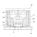
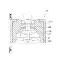
- FIG. 1 is a cross-sectional view of a lens unit used in the present embodiment.
- a lens unit LU constituting an imaging apparatus by assembling a solid-state imaging device (not shown) on the image side includes an optical aperture S, in order from the object side, in a lens frame MF inserted in the housing CS.
- the lens LS1, the lens LS2, the lens LS3, and the lens LS4 are fixed.
- the optical diaphragm S is made of a plate member having a circular opening at the center, and is not limited to the outermost aspect in the optical axis direction as shown in FIG. 1, but is arranged at various positions, for example, as shown in FIG. 10.
- the optical aperture S can also be provided inside (between lenses LS2 and LS3 in this modification).
- the optical aperture S is on the outermost side, it is easy to position the optical aperture S.
- this embodiment which will be described later, is performed as in the case of the optical aperture S being on the outermost side.
- Defective product inspection etc. can be performed depending on the form.
- a predetermined position P here, a position corresponding to the imaging surface of the solid-state imaging device when the solid-state imaging device is combined
- a condensing spot is formed on the surface. It is assumed that the image-side and object-side end surfaces of the casing CS are accurately orthogonal to the optical axis of the lens.
- the housing and the lens frame may be referred to as a lens frame.
- FIG. 2 is a schematic perspective view of the aperture position measuring apparatus according to the present embodiment.
- the vertical direction is the Z direction
- the horizontal direction is the X direction and the Y direction.
- an autocollimator AC and a tilt stage TS are installed on the surface plate G.
- the tilt stage TS is configured to be able to tilt the held glass plate GL.
- a lens unit LU which is a measurement target is placed with the object side facing the autocollimator AC side (see FIG. 3).
- the autocollimator AC including a laser light source having a visible light wavelength constitutes an inclination detecting means, emits a laser beam L which is parallel light upward, detects a reflected image thereof, and displays it on the monitor MN. It is like that.
- An aperture (measuring diaphragm) between the autocollimator AC and the glass plate GL unnecessary light can be cut and measurement accuracy may be improved.
- a resin plate may be used instead of the glass plate GL.
- An ND filter ND as a light reducing member is disposed above the lens unit LU, and a microscope MS is disposed above the ND filter ND.
- the ND filter ND may be provided on the object side of the lens unit LU.
- the microscope MS can be moved in the Z direction by the Z direction stage ZS, can be moved in the X direction by the X direction stage XS, and can be moved in the Y direction by the Y direction stage YS.
- Each stage is provided with a drive source (not shown) and a sensor (movement amount detection means) for detecting the movement amount, and detects the Z direction movement amount, the X direction movement amount, and the Y direction movement amount,
- the data is input to a central processing unit CONT that is a computing means.
- the microscope MS that also serves as the first detection means and the second detection means has an optical system OS and an image sensor CCD, images the light that has passed through the optical system OS with the image sensor CCD, and displays an image on the monitor MT. It is like that.
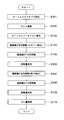
- FIG. 4 is a flowchart showing the operation of the aperture position measuring apparatus. With reference to FIG. 4, the operation of the aperture position measuring apparatus will be described. First, the lens unit LU to be measured is placed with the object side facing the glass plate GL as shown in FIG.
- step S101 the autocollimator AC is caused to emit pre-light.
- the pre-emission light is reflected by the glass plate GL on which the lens unit LU to be measured is placed and returns to the autocollimator AC.
- tilt adjustment is performed in step S102 to level the glass plate GL.
- the optical axes of the lenses LS1 to LS4 of the lens unit LU are parallel to the laser light L that is the main emitted light of the autocollimator AC.
- step S103 the laser light L, which is parallel light emitted from the autocollimator AC, passes through the glass plate GL and enters the lenses LS1 to LS4 of the lens unit LU through the optical aperture S. Then, the laser beam L forms a focused spot at a predetermined upper position.
- the image of the focused spot is observed with the microscope MS through the ND filter ND. More specifically, in step S104, the microscope MS is moved in the Z direction so that the diameter of the focused spot is adjusted to 20 ⁇ m or less. Note that the smaller the focused spot, the smaller the roundness of the spot, and the higher the measurement accuracy, which is preferable. In the experimental results, the spot roundness was 3% or less with respect to the diameter (roundness of 0.6 ⁇ m or less with respect to 20 ⁇ m of the focused spot).
- step S105 the microscope MS is moved in the X direction and the Y direction so that the image of the focused spot matches the reference position (for example, the center) of the monitor MT.
- step S106 the central processing unit CONT obtains the XY coordinates of the focused spot from the movement amount of the microscope MS.
- step S107 the microscope MS is lowered in the Z direction and adjusted so that the optical aperture S is in focus.
- the image of the optical aperture S illuminated by illumination light or room light passes through the optical system OS of the microscope MS and forms an image on the light receiving surface of the image sensor CCD, so that the image is displayed on the monitor MT ( (See FIG. 6).
- the microscope MS is moved in the X and Y directions, and the center of the image of the optical aperture S is the reference position (for example, the center) of the monitor MT. To match.
- the central processing unit CONT obtains the XY coordinates of the center of the optical aperture S from the movement amount of the microscope MS.
- step S110 the central processing unit CONT calculates the amount of deviation from the obtained XY coordinates of the focused spot and the XY coordinates of the center of the optical aperture S. This completes the operation of the aperture position measuring device.
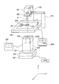
- FIG. 7 is a schematic perspective view of the aperture positioning device according to the present embodiment.
- the aperture positioning device constitutes a part of the manufacturing apparatus of the lens unit LU.
- the vertical direction is the Z direction
- the horizontal direction is the X direction and the Y direction.
- the frame FR is provided with an autocollimator AC and a tilt stage TS which are tilt detecting means.
- the tilt stage TS is configured to tilt the autocollimator AC with respect to the frame FR.
- a lens unit LU to be measured (the optical aperture S is not fixed) is placed with the object side facing the autocollimator AC side (FIG. 8).
- the autocollimator AC emits a laser beam L that is parallel light downward, detects a reflected image thereof, and displays the reflected image on the monitor MN.
- an aperture measuring diaphragm
- ND filter ND as a light reducing member is disposed between autocollimator AC and lens unit LU, and microscope MS is disposed below glass plate GL.
- the glass plate GL may be used as the ND filter ND.
- the microscope MS can be moved in the Z direction by the Z direction stage ZS, can be moved in the X direction by the X direction stage XS, and can be moved in the Y direction by the Y direction stage YS.
- Each stage is provided with a drive source (not shown) and a sensor (movement amount detection means) for detecting the movement amount, and detects the Z direction movement amount, the X direction movement amount, and the Y direction movement amount,
- the data is input to the central processing unit CONT.
- the microscope MS has an optical system OS and an image sensor CCD, and images the light that has passed through the optical system OS with the image sensor CCD and displays an image on the monitor MT.
- the lenses LS1 to LS4 are fixed to the lens frame MF, but the optical aperture S is not fixed to the lens frame MF, and is fixed by the jig JG. Assume that it is in a held state. This is called provisional retention.
- the jig JG as a holding member includes an opening JG1 having a size that does not hinder the laser light L incident on the optical aperture S, and can hold the optical aperture S on the lower surface by, for example, vacuum suction or electrostatic suction. Yes. Further, as shown in FIG. 7, the jig JG can be moved in the X direction and the Y direction by the driving device DR.
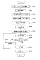
- FIG. 9 is a flowchart showing the operation of the aperture positioning device. With reference to FIG. 9, the operation of the aperture position measuring apparatus will be described.
- the autocollimator AC is caused to emit pre-light.
- the pre-emission light is reflected by the glass plate GL (or a flange orthogonal to the optical axis of the lens LS4) on which the lens unit LU to be measured is placed, and returns to the autocollimator AC.
- tilt adjustment is performed in step S202, and the autocollimator AC is directly opposed to the glass plate GL with respect to the glass plate GL.
- the optical axes of the lenses LS1 to LS4 of the lens unit LU are coaxial with the laser light L that is the main emitted light of the autocollimator AC. This operation may be performed first when the optical aperture S is assembled to a plurality of lens units LU.
- step S203 the laser beam L which is parallel light is emitted from the autocollimator AC, and is incident on the lenses LS1 to LS4 of the lens unit LU through the ND filter ND and the optical diaphragm S held by the jig JG. Then, the laser beam L forms a condensing spot on the glass plate GL. An image of the focused spot is observed with a microscope MS below the glass plate GL. More specifically, in step S204, the microscope MS is moved in the Z direction so that the focus position of the optical system OS is adjusted to a position where the focused spot of the glass plate GL is in focus.
- the image of the focused spot passes through the optical system OS of the microscope MS and forms an image on the light receiving surface of the image sensor CCD, the image is displayed on the monitor MT (see FIG. 5). Furthermore, in step S105, the microscope MS is moved in the X direction and the Y direction so that the image of the focused spot matches the reference position (for example, the center) of the monitor MT. In step S206, the central processing unit CONT determines this position as the optical axis position.
- step S207 the microscope MS is raised in the Z direction and adjusted so that the optical aperture S is in focus.
- the image of the optical aperture S illuminated by illumination light or room light passes through the optical system OS of the microscope MS and forms an image on the light receiving surface of the image sensor CCD, so that the image is displayed on the monitor MT ( (See FIG. 6).
- the central processing unit CONT obtains the center of the image of the optical aperture S in step S208, and in step S209, the center position of the monitor MT is set to the reference position (that is, the optical axis). It is judged whether it has shifted
- step S210 the optical aperture S is moved in the X direction or the Y direction together with the jig JG.
- step S208 the center of the image of the optical aperture S is obtained, and in step S209, it is determined whether or not the center of the monitor MT is shifted from the reference position (ie, the optical axis). This is repeated until the two match.
- step S211 a UV adhesive (not shown) is discharged from the gap of the jig JG.
- the optical aperture S is fixed to the lens frame MF.
- the jig JG opens the optical aperture S in step S212. This completes the operation of the aperture positioning device.
- the inventor prepares lens units A and B with the optical aperture S assembled thereto, and measures the center position of the optical aperture S in advance with a microscope having an XY stage for each lens unit, The value obtained by measuring the imaging position and calculating the deviation from the center position of the optical aperture is taken as measurement result 1 (Example), and the deviation from the virtual optical axis position calculated from the lens barrel outer diameter and the center position of the optical aperture is calculated. The measured value is taken as measurement result 2 (comparative example), a mold transfer mark is attached to the center of the optical surface (on the lens optical axis) of the lens on the image side forming the lens unit, and the position of the physically specified optical axis is determined.
- a value obtained by measuring with a microscope and calculating a deviation from the center position of the optical aperture was defined as a measurement result 3.
- the amount of deviation is compared by a scalar amount ⁇ (x 2 + y 2 ).
- XA is the center of the optical aperture
- XB is a virtual optical axis calculated from the outer diameter of the lens frame, but is shifted for easy understanding.
- the deviation amount of the measurement result 3 is assumed to be a true value (reference) and compared with the measurement results 1 and 2.
- the measurement results 1 to 3 are shown in Table 1.
- the diaphragm position measuring method and the diaphragm position measuring apparatus of the present invention it is possible to accurately measure the amount of deviation between the center of the optical diaphragm and the optical axis.
- the aperture positioning method and the aperture positioning device lens unit of the present invention the optical aperture can be arranged with high accuracy. For this reason, for example, an accurate imaging device using a solid-state imaging device can be realized.
Landscapes
- Physics & Mathematics (AREA)
- General Physics & Mathematics (AREA)
- Chemical & Material Sciences (AREA)
- Analytical Chemistry (AREA)
- Optics & Photonics (AREA)
- Length Measuring Devices By Optical Means (AREA)
- Lens Barrels (AREA)
- Mounting And Adjusting Of Optical Elements (AREA)
- Testing Of Optical Devices Or Fibers (AREA)
Abstract
Description
前記レンズユニットのレンズに該レンズの光軸に平行な平行光を入射して集光スポットを形成するステップと、
前記集光スポットの位置を検出するステップと、
前記光学絞りの中心位置を検出するステップと、
前記集光スポットの位置と前記光学絞りの中心位置とのズレ量を求めるステップとを有することを特徴とする。
少なくとも一部が光を透過可能な透過部とされ、前記レンズユニットを該透過部に重ねて支持する支持台と、
前記レンズユニットに向けて該レンズユニットのレンズ光軸に平行な平行光を照射する光照射装置と、
前記平行光が前記レンズユニットのレンズを透過したときに形成される集光スポットの位置を検出する第1検出手段と、
前記光学絞りの中心位置を検出する第2検出手段と、
検出された前記集光スポットの位置と前記光学絞りの中心位置とのズレ量を求める演算手段とを有することを特徴とする。
前記レンズユニットのレンズに該レンズの光軸に平行な平行光を入射して集光スポットを形成するステップと、
前記レンズユニットに対して、前記光学絞りを仮決めするように保持するステップと、
前記光学絞りの中心位置を検出するステップと、
前記集光スポットの位置に対して、前記光学絞りの中心位置が合致するように、前記光学絞りを変位させるステップと、
前記集光スポットの位置に対して、前記光学絞りの中心位置が合致したら、前記光学絞りを前記レンズユニットに固定するステップと、を有することを特徴とする。
少なくとも一部が光を透過可能な素材からなり、前記レンズユニットを支持する支持台と、
前記レンズユニットに対して、前記光学絞りを仮決めするように保持する保持部材と、
前記レンズユニットに向けて該レンズユニットのレンズ光軸に平行な平行光を照射する光照射装置と、
前記平行光が前記レンズユニットのレンズを透過したときに形成される集光スポットの位置を検出する第1検出手段と、
前記光学絞りの中心位置を検出する第2検出手段と、
検出された前記集光スポットの位置と前記光学絞りの中心位置とのズレ量が小さくなるように、前記光学絞りと共に前記保持部材を変位させる駆動装置と、を有することを特徴とする。

CCD 撮像素子
CONT 中央演算装置
CS 筐体
DR 駆動装置
FR フレーム
G 定盤
GL ガラス板
JG 治具
JG1 開口
L レーザ光
LS1~LS4 レンズ
LU レンズユニット
MF 鏡枠
MN モニタ
MS 顕微鏡
MT モニタ
ND NDフィルタ
OS 光学系
P 所定位置
S 光学絞り
TS チルトステージ
XS X方向ステージ
YS Y方向ステージ
ZS Z方向ステージ
Claims (18)
- 光学絞りと、レンズと、前記光学絞り及び前記レンズを保持する鏡枠と、を有するレンズユニットにおける前記光学絞りの位置の測定方法において、
前記レンズユニットのレンズに該レンズの光軸に平行な平行光を入射して集光スポットを形成するステップと、
前記集光スポットの位置を検出するステップと、
前記光学絞りの中心位置を検出するステップと、
前記集光スポットの位置と前記光学絞りの中心位置とのズレ量を求めるステップとを有することを特徴とする絞り位置測定方法。 - 前記光学絞りの中心位置を検出するステップは、前記光学絞りの内径形状から幾何学的に中心位置を求めることを特徴とする請求項1に記載の絞り位置測定方法。
- 光学絞りと、レンズと、前記光学絞り及び前記レンズを保持する鏡枠と、を有するレンズユニットにおける前記光学絞りの位置の測定装置において、
少なくとも一部が光を透過可能な透過部とされ、前記レンズユニットを該透過部に重ねて支持する支持台と、
前記レンズユニットに向けて該レンズユニットのレンズ光軸に平行な平行光を照射する光照射装置と、
前記平行光が前記レンズユニットのレンズを透過したときに形成される集光スポットの位置を検出する第1検出手段と、
前記光学絞りの中心位置を検出する第2検出手段と、
検出された前記集光スポットの位置と前記光学絞りの中心位置とのズレ量を求める演算手段と、を有することを特徴とする絞り位置測定装置。 - 前記第1検出手段及び/又は前記第2検出手段と前記支持台とを、前記平行光の出射方向に相対的に移動させるZ方向移動ステージを有することを特徴とする請求項3に記載の絞り位置測定装置。
- 前記第1検出手段及び/又は前記第2検出手段と前記支持台とを、前記平行光の出射方向に直交する方向に相対的に移動させるXY方向移動ステージと、前記XY方向移動ステージの移動量を検出する移動量検出手段とを有することを特徴とする請求項3又は4に記載の絞り位置測定装置。
- 前記平行光の出射方向に対して、前記光照射装置と前記支持台とを相対的に傾けるチルトステージを有することを特徴とする請求項3乃至5のいずれか1項に記載の絞り位置測定装置。
- 前記平行光と前記支持台との相対的な傾きを検出する傾き検出手段を有することを特徴とする請求項6に記載の絞り位置測定装置。
- 前記第1検出手段と前記支持台との間に減光部材を挿入したことを特徴とする請求項3乃至7のいずれか1項に記載の絞り位置測定装置。
- 前記第1検出手段が前記第2検出手段を兼ねていることを特徴とする請求項3乃至8のいずれか1項に記載の絞り位置測定装置。
- レンズと、前記レンズを保持する鏡枠と、を有するレンズユニットに対して、光学絞りを位置決めする光学絞りの位置決め方法において、
前記レンズユニットのレンズに該レンズの光軸に平行な平行光を入射して集光スポットを形成するステップと、
前記レンズユニットに対して、前記光学絞りを仮決めするように保持するステップと、
前記光学絞りの中心位置を検出するステップと、
前記集光スポットの位置に対して、前記光学絞りの中心位置が合致するように、前記光学絞りを変位させるステップと、
前記集光スポットの位置に対して、前記光学絞りの中心位置が合致したら、前記光学絞りを前記レンズユニットに固定するステップと、を有することを特徴とする絞り位置決め方法。 - 前記光学絞りの中心位置を検出するステップは、前記光学絞りの内径形状から幾何学的に中心位置を求めることを特徴とする請求項10に記載の絞り位置決め方法。
- レンズと、前記レンズを保持する鏡枠とを有するレンズユニットに対して、光学絞りを位置決めする光学絞りの位置決め装置において、
少なくとも一部が光を透過可能な素材からなり、前記レンズユニットを支持する支持台と、
前記レンズユニットに対して、前記光学絞りを仮決めするように保持する保持部材と、
前記レンズユニットに向けて該レンズユニットのレンズ光軸に平行な平行光を照射する光照射装置と、
前記平行光が前記レンズユニットのレンズを透過したときに形成される集光スポットの位置を検出する第1検出手段と、
前記光学絞りの中心位置を検出する第2検出手段と、
検出された前記集光スポットの位置と前記光学絞りの中心位置とのズレ量が小さくなるように、前記光学絞りと共に前記保持部材を変位させる駆動装置と、を有することを特徴とする絞り位置決め装置。 - 前記第1検出手段又は前記第2検出手段と前記支持台とを、前記平行光の出射方向に相対的に移動させるZ方向移動ステージを有することを特徴とする請求項12に記載の絞り位置決め装置。
- 前記第1検出手段又は前記第2検出手段と前記支持台とを、前記平行光の出射方向に直交する方向に相対的に移動させるXY方向移動ステージと、前記XY方向移動ステージの移動量を検出する移動量検出手段とを有することを特徴とする請求項12又は13に記載の絞り位置決め装置。
- 前記平行光の出射方向に対して、前記光源と前記支持台とを相対的に傾けるチルトステージを有することを特徴とする請求項12乃至14のいずれか1項に記載の絞り位置決め装置。
- 前記平行光と前記支持台との相対的な傾きを検出する傾き検出手段を有することを特徴とする請求項15に記載の絞り位置決め装置。
- 前記第1検出手段と前記支持台との間に減光部材を挿入したことを特徴とする請求項12乃至16のいずれか1項に記載の絞り位置決め装置。
- 前記第1検出手段が前記第2検出手段を兼ねていることを特徴とする請求項12乃至17のいずれか1項に記載の絞り位置決め装置。
Priority Applications (2)
| Application Number | Priority Date | Filing Date | Title |
|---|---|---|---|
| JP2012525373A JPWO2012011406A1 (ja) | 2010-07-23 | 2011-07-12 | 絞り位置測定方法、絞り位置測定装置、絞り位置決め方法及び絞り位置決め装置 |
| US13/811,536 US20130120762A1 (en) | 2010-07-23 | 2011-07-12 | Diaphragm position measuring method, diaphragm position measuring apparatus, diaphragm positioning method and diaphragm positioning apparatus |
Applications Claiming Priority (2)
| Application Number | Priority Date | Filing Date | Title |
|---|---|---|---|
| JP2010165828 | 2010-07-23 | ||
| JP2010-165828 | 2010-07-23 |
Publications (1)
| Publication Number | Publication Date |
|---|---|
| WO2012011406A1 true WO2012011406A1 (ja) | 2012-01-26 |
Family
ID=45496833
Family Applications (1)
| Application Number | Title | Priority Date | Filing Date |
|---|---|---|---|
| PCT/JP2011/065835 Ceased WO2012011406A1 (ja) | 2010-07-23 | 2011-07-12 | 絞り位置測定方法、絞り位置測定装置、絞り位置決め方法及び絞り位置決め装置 |
Country Status (4)
| Country | Link |
|---|---|
| US (1) | US20130120762A1 (ja) |
| JP (1) | JPWO2012011406A1 (ja) |
| TW (1) | TWI461675B (ja) |
| WO (1) | WO2012011406A1 (ja) |
Cited By (2)
| Publication number | Priority date | Publication date | Assignee | Title |
|---|---|---|---|---|
| CN111076906A (zh) * | 2020-01-16 | 2020-04-28 | 中山市冠林光电科技有限公司 | 一种镜片光圈检测装置 |
| CN115816391A (zh) * | 2022-11-18 | 2023-03-21 | 茂莱(南京)仪器有限公司 | 一种应用于透镜的精准定位装置及定位方法 |
Families Citing this family (5)
| Publication number | Priority date | Publication date | Assignee | Title |
|---|---|---|---|---|
| TWI561794B (en) * | 2012-12-13 | 2016-12-11 | Hon Hai Prec Ind Co Ltd | Method for measuring static inclined degree of camera actuator |
| CN107884422B (zh) * | 2017-01-04 | 2023-08-11 | 浙江舜宇光学有限公司 | 光学检测设备 |
| CN107505122A (zh) * | 2017-08-31 | 2017-12-22 | 浙江舜宇光学有限公司 | 光学检测设备 |
| CN114909989B (zh) * | 2021-02-09 | 2023-06-30 | 上海微电子装备(集团)股份有限公司 | 视场光阑位置测量装置及测量方法 |
| CN114964065B (zh) * | 2022-06-21 | 2026-01-13 | 洛阳微米光电技术有限公司 | 一种红外光学镜片的中心偏检测方法 |
Citations (5)
| Publication number | Priority date | Publication date | Assignee | Title |
|---|---|---|---|---|
| JPH03128206U (ja) * | 1990-03-30 | 1991-12-24 | ||
| JP2005157253A (ja) * | 2003-10-30 | 2005-06-16 | Hitachi Maxell Ltd | 光学素子の光軸検出方法、光学ユニットの組み立て方法、光学ユニット、光軸検出装置、光学ユニットの組立装置 |
| JP2005258329A (ja) * | 2004-03-15 | 2005-09-22 | Matsushita Electric Ind Co Ltd | 複合レンズおよびそれの成形金型 |
| JP2009097858A (ja) * | 2007-10-12 | 2009-05-07 | Olympus Corp | 偏心測定機 |
| JP2009157279A (ja) * | 2007-12-27 | 2009-07-16 | Sharp Corp | レンズユニット、撮像装置、電子機器、及びレンズユニットの組立方法 |
Family Cites Families (13)
| Publication number | Priority date | Publication date | Assignee | Title |
|---|---|---|---|---|
| US4772123A (en) * | 1986-11-24 | 1988-09-20 | American Telephone And Telegraph Company, At&T Bell Laboratories | Alignment of optical components |
| JP3208902B2 (ja) * | 1993-03-11 | 2001-09-17 | ミノルタ株式会社 | レンズ系光軸調整装置及びレンズ系光軸調整方法 |
| US6437912B2 (en) * | 1999-12-08 | 2002-08-20 | Olympus Optical Co., Ltd. | Microscope, transillumination condenser therefor, and optical element slider |
| JP4595184B2 (ja) * | 2000-10-02 | 2010-12-08 | コニカミノルタホールディングス株式会社 | 光ピックアップ装置及び対物レンズ |
| JP4613357B2 (ja) * | 2000-11-22 | 2011-01-19 | 株式会社ニコン | 光学的位置ずれ測定装置の調整装置および方法 |
| JP4144384B2 (ja) * | 2003-03-11 | 2008-09-03 | セイコーエプソン株式会社 | プロジェクタ |
| CN100456083C (zh) * | 2004-06-30 | 2009-01-28 | 奥林巴斯株式会社 | 光学部件的评价装置和评价方法 |
| JP4604651B2 (ja) * | 2004-10-29 | 2011-01-05 | 株式会社ニコン | 焦点検出装置 |
| JP2006330210A (ja) * | 2005-05-24 | 2006-12-07 | Olympus Corp | レンズの心出し方法及び装置 |
| JP2007240583A (ja) * | 2006-03-06 | 2007-09-20 | Matsushita Electric Ind Co Ltd | レンズユニットおよびその製造方法 |
| EP1927876A1 (de) * | 2006-08-10 | 2008-06-04 | MEKRA Lang GmbH & Co. KG | Weitwinkelobjektiv und Weitwinkelkamera |
| JP3128206U (ja) * | 2006-10-18 | 2006-12-28 | 一品光学工業股▲ふん▼有限公司 | 偏心測定検査用溝入り成形レンズ |
| JP5136778B2 (ja) * | 2007-08-20 | 2013-02-06 | セイコーエプソン株式会社 | ラインヘッド及びそれを用いた画像形成装置 |
-
2011
- 2011-07-12 US US13/811,536 patent/US20130120762A1/en not_active Abandoned
- 2011-07-12 JP JP2012525373A patent/JPWO2012011406A1/ja active Pending
- 2011-07-12 WO PCT/JP2011/065835 patent/WO2012011406A1/ja not_active Ceased
- 2011-07-14 TW TW100124979A patent/TWI461675B/zh not_active IP Right Cessation
Patent Citations (5)
| Publication number | Priority date | Publication date | Assignee | Title |
|---|---|---|---|---|
| JPH03128206U (ja) * | 1990-03-30 | 1991-12-24 | ||
| JP2005157253A (ja) * | 2003-10-30 | 2005-06-16 | Hitachi Maxell Ltd | 光学素子の光軸検出方法、光学ユニットの組み立て方法、光学ユニット、光軸検出装置、光学ユニットの組立装置 |
| JP2005258329A (ja) * | 2004-03-15 | 2005-09-22 | Matsushita Electric Ind Co Ltd | 複合レンズおよびそれの成形金型 |
| JP2009097858A (ja) * | 2007-10-12 | 2009-05-07 | Olympus Corp | 偏心測定機 |
| JP2009157279A (ja) * | 2007-12-27 | 2009-07-16 | Sharp Corp | レンズユニット、撮像装置、電子機器、及びレンズユニットの組立方法 |
Cited By (2)
| Publication number | Priority date | Publication date | Assignee | Title |
|---|---|---|---|---|
| CN111076906A (zh) * | 2020-01-16 | 2020-04-28 | 中山市冠林光电科技有限公司 | 一种镜片光圈检测装置 |
| CN115816391A (zh) * | 2022-11-18 | 2023-03-21 | 茂莱(南京)仪器有限公司 | 一种应用于透镜的精准定位装置及定位方法 |
Also Published As
| Publication number | Publication date |
|---|---|
| JPWO2012011406A1 (ja) | 2013-09-09 |
| TW201217766A (en) | 2012-05-01 |
| TWI461675B (zh) | 2014-11-21 |
| US20130120762A1 (en) | 2013-05-16 |
Similar Documents
| Publication | Publication Date | Title |
|---|---|---|
| WO2012011406A1 (ja) | 絞り位置測定方法、絞り位置測定装置、絞り位置決め方法及び絞り位置決め装置 | |
| US7656513B2 (en) | System for checking centration of lens surfaces of aspheric lens | |
| EP2896949B1 (en) | Device, system and method for rapidly and comprehensively detecting lens actuator | |
| JP6561327B2 (ja) | 光学検査装置、鏡筒の製造方法、および光学検査方法 | |
| CN102944171B (zh) | 一种芯片位置和倾角检测装置及方法 | |
| CN212378695U (zh) | 检测机构 | |
| US20140160267A1 (en) | Image Pickup Apparatus | |
| JPWO2014073262A1 (ja) | 撮像素子位置検出装置 | |
| KR101653176B1 (ko) | 자동초점거리 조절 기능을 갖는 렌즈 검사장치 | |
| CN116105638A (zh) | 一种u型转台同轴度检测系统及检测方法 | |
| CN112748564A (zh) | 一种显微装置及显微装置的调焦方法 | |
| CN106461382B (zh) | 五轴光学检测系统 | |
| KR101447857B1 (ko) | 렌즈 모듈 이물 검사 시스템 | |
| JP2011151551A (ja) | カメラモジュールの製造方法及び装置 | |
| JP2006030256A (ja) | 撮像装置の焦点調整方法および焦点調整装置 | |
| JP2014089257A (ja) | レンズチルト検出装置およびレンズチルト検出方法、並びに、レンズチルト検出装置を用いたカメラモジュール組み立て方法 | |
| JP5120233B2 (ja) | 撮像モジュールの検査装置及び撮像モジュールの検査方法及び電子機器モジュールの製造方法 | |
| US8854611B2 (en) | Method for determining the optic center of a lens blank | |
| CN212646046U (zh) | 一种镜头光心与成像传感器感光面中心对齐系统 | |
| CN112946849A (zh) | 一种远心光学系统镜头 | |
| Chen et al. | An image based optical lens eccentric error inspection system | |
| TWM583937U (zh) | 檢測模組 | |
| JP5566266B2 (ja) | エッジ検出方法およびエッジ検出装置 | |
| CN202511769U (zh) | 一种微小物体表面积精密测量装置 | |
| CN117871536A (zh) | 一种用于表面缺陷检测的大范围变距离测量装置 |
Legal Events
| Date | Code | Title | Description |
|---|---|---|---|
| 121 | Ep: the epo has been informed by wipo that ep was designated in this application |
Ref document number: 11809580 Country of ref document: EP Kind code of ref document: A1 |
|
| WWE | Wipo information: entry into national phase |
Ref document number: 2012525373 Country of ref document: JP |
|
| WWE | Wipo information: entry into national phase |
Ref document number: 13811536 Country of ref document: US |
|
| NENP | Non-entry into the national phase |
Ref country code: DE |
|
| 122 | Ep: pct application non-entry in european phase |
Ref document number: 11809580 Country of ref document: EP Kind code of ref document: A1 |