WO2012008307A1 - 空隙形成用回転ツール及び空隙形成方法 - Google Patents
空隙形成用回転ツール及び空隙形成方法 Download PDFInfo
- Publication number
- WO2012008307A1 WO2012008307A1 PCT/JP2011/064934 JP2011064934W WO2012008307A1 WO 2012008307 A1 WO2012008307 A1 WO 2012008307A1 JP 2011064934 W JP2011064934 W JP 2011064934W WO 2012008307 A1 WO2012008307 A1 WO 2012008307A1
- Authority
- WO
- WIPO (PCT)
- Prior art keywords
- gap
- tool
- stirring pin
- outer diameter
- spiral groove
- Prior art date
- Legal status (The legal status is an assumption and is not a legal conclusion. Google has not performed a legal analysis and makes no representation as to the accuracy of the status listed.)
- Ceased
Links
Images
















Classifications
-
- B—PERFORMING OPERATIONS; TRANSPORTING
- B23—MACHINE TOOLS; METAL-WORKING NOT OTHERWISE PROVIDED FOR
- B23K—SOLDERING OR UNSOLDERING; WELDING; CLADDING OR PLATING BY SOLDERING OR WELDING; CUTTING BY APPLYING HEAT LOCALLY, e.g. FLAME CUTTING; WORKING BY LASER BEAM
- B23K20/00—Non-electric welding by applying impact or other pressure, with or without the application of heat, e.g. cladding or plating
- B23K20/12—Non-electric welding by applying impact or other pressure, with or without the application of heat, e.g. cladding or plating the heat being generated by friction; Friction welding
- B23K20/122—Non-electric welding by applying impact or other pressure, with or without the application of heat, e.g. cladding or plating the heat being generated by friction; Friction welding using a non-consumable tool, e.g. friction stir welding
- B23K20/1245—Non-electric welding by applying impact or other pressure, with or without the application of heat, e.g. cladding or plating the heat being generated by friction; Friction welding using a non-consumable tool, e.g. friction stir welding characterised by the apparatus
- B23K20/1255—Tools therefor, e.g. characterised by the shape of the probe
-
- B—PERFORMING OPERATIONS; TRANSPORTING
- B23—MACHINE TOOLS; METAL-WORKING NOT OTHERWISE PROVIDED FOR
- B23K—SOLDERING OR UNSOLDERING; WELDING; CLADDING OR PLATING BY SOLDERING OR WELDING; CUTTING BY APPLYING HEAT LOCALLY, e.g. FLAME CUTTING; WORKING BY LASER BEAM
- B23K20/00—Non-electric welding by applying impact or other pressure, with or without the application of heat, e.g. cladding or plating
- B23K20/12—Non-electric welding by applying impact or other pressure, with or without the application of heat, e.g. cladding or plating the heat being generated by friction; Friction welding
- B23K20/122—Non-electric welding by applying impact or other pressure, with or without the application of heat, e.g. cladding or plating the heat being generated by friction; Friction welding using a non-consumable tool, e.g. friction stir welding
-
- B—PERFORMING OPERATIONS; TRANSPORTING
- B23—MACHINE TOOLS; METAL-WORKING NOT OTHERWISE PROVIDED FOR
- B23K—SOLDERING OR UNSOLDERING; WELDING; CLADDING OR PLATING BY SOLDERING OR WELDING; CUTTING BY APPLYING HEAT LOCALLY, e.g. FLAME CUTTING; WORKING BY LASER BEAM
- B23K2101/00—Articles made by soldering, welding or cutting
- B23K2101/18—Sheet panels
-
- B—PERFORMING OPERATIONS; TRANSPORTING
- B23—MACHINE TOOLS; METAL-WORKING NOT OTHERWISE PROVIDED FOR
- B23K—SOLDERING OR UNSOLDERING; WELDING; CLADDING OR PLATING BY SOLDERING OR WELDING; CUTTING BY APPLYING HEAT LOCALLY, e.g. FLAME CUTTING; WORKING BY LASER BEAM
- B23K2103/00—Materials to be soldered, welded or cut
- B23K2103/08—Non-ferrous metals or alloys
- B23K2103/10—Aluminium or alloys thereof
-
- B—PERFORMING OPERATIONS; TRANSPORTING
- B23—MACHINE TOOLS; METAL-WORKING NOT OTHERWISE PROVIDED FOR
- B23K—SOLDERING OR UNSOLDERING; WELDING; CLADDING OR PLATING BY SOLDERING OR WELDING; CUTTING BY APPLYING HEAT LOCALLY, e.g. FLAME CUTTING; WORKING BY LASER BEAM
- B23K2103/00—Materials to be soldered, welded or cut
- B23K2103/08—Non-ferrous metals or alloys
- B23K2103/12—Copper or alloys thereof
-
- B—PERFORMING OPERATIONS; TRANSPORTING
- B23—MACHINE TOOLS; METAL-WORKING NOT OTHERWISE PROVIDED FOR
- B23K—SOLDERING OR UNSOLDERING; WELDING; CLADDING OR PLATING BY SOLDERING OR WELDING; CUTTING BY APPLYING HEAT LOCALLY, e.g. FLAME CUTTING; WORKING BY LASER BEAM
- B23K2103/00—Materials to be soldered, welded or cut
- B23K2103/08—Non-ferrous metals or alloys
- B23K2103/14—Titanium or alloys thereof
-
- B—PERFORMING OPERATIONS; TRANSPORTING
- B23—MACHINE TOOLS; METAL-WORKING NOT OTHERWISE PROVIDED FOR
- B23K—SOLDERING OR UNSOLDERING; WELDING; CLADDING OR PLATING BY SOLDERING OR WELDING; CUTTING BY APPLYING HEAT LOCALLY, e.g. FLAME CUTTING; WORKING BY LASER BEAM
- B23K2103/00—Materials to be soldered, welded or cut
- B23K2103/08—Non-ferrous metals or alloys
- B23K2103/15—Magnesium or alloys thereof
Definitions
- the present invention relates to a gap forming rotary tool for forming a gap in a metal member by friction stirring and a gap forming method using the same.
- Patent Document 1 describes a gap forming rotation tool including a shoulder portion and a stirring pin suspended from the bottom surface of the shoulder portion.
- a thread groove is formed on the outer peripheral surface of the stirring pin.
- the gap may be crushed or a hole communicating with the gap and the surface of the metal member (hereinafter also referred to as “surface defect”) may be formed.
- the present invention provides a void forming rotary tool and a void forming method in which voids are not easily crushed and surface defects are not easily generated when voids are formed inside a metal member by friction stirring. Is an issue.
- the present invention that solves such a problem is a gap forming rotary tool that is used when a gap is formed in a metal member by friction stirring, and has a shoulder portion and a stirring pin that hangs down from the shoulder portion.
- a spiral groove is formed on the outer peripheral surface of the stirring pin, and a value obtained by dividing the outer diameter of the shoulder portion by the outer diameter of the tip of the stirring pin is 1.4 or more and 2.2 or less. It is characterized by.
- the plastic fluidized metal is suitably scraped, and the scraped metal can be pressed by the bottom surface of the shoulder portion, so that the gap is not easily crushed and surface defects are unlikely to occur in the metal member. .
- the value obtained by dividing the outer diameter of the shoulder portion by the outer diameter of the tip end of the stirring pin is less than 1.4, the scraped metal cannot be held by the bottom surface of the shoulder portion, and surface defects are likely to occur.
- the value obtained by dividing the outer diameter of the shoulder portion by the outer diameter of the tip of the stirring pin is larger than 2.2, it is difficult for the metal to be scraped from the shoulder portion, so that the voids in the metal member are easily crushed.
- the load applied to the spindle motor of the friction stirrer increases.
- an angle of the spiral groove with respect to a reference plane having a normal line in the axial direction of the stirring pin is 20 degrees or more and 40 degrees or less. According to such a configuration, the gap is less likely to be crushed.
- the angle of the spiral groove with respect to the reference surface is less than 20 degrees, the angle is shallow, and thus the metal is hardly scraped from the shoulder portion.
- the angle of the spiral groove with respect to the reference surface is larger than 40 degrees, the length of the spiral groove with respect to the stirring pin is shortened, so that the metal is hardly scraped from the shoulder portion. Therefore, in any case, the gap may be crushed.
- the spiral groove is wound around the stirring pin one or more times. If the spiral groove winding is less than one turn, the plastic fluidized metal may remain on one of the side walls of the void, and the void may be crushed. Since it is fluidized, it is possible to avoid crushing the gap.
- the stirring pin includes a spiral groove portion in which the spiral groove is formed and a flat surface portion in which the spiral groove is not formed, and the spiral groove portion is cut from a tip of the stirring pin. Is preferred. According to this structure, a space
- a protrusion is provided on the bottom surface of the shoulder portion, and the protrusion is formed in a spiral shape around the stirring pin. According to such a configuration, the formed gap has a relatively regular shape.
- a notch that is notched in the radial direction of the bottom surface of the shoulder portion is formed in the protrusion. According to this configuration, the plastic fluidized metal is easily collected around the base end of the stirring pin, and the metal is easily scraped from the notch. Thereby, a comparatively large space
- gap can be formed.
- the stirring pin preferably has a constant outer diameter from the distal end to the proximal end. According to such a configuration, the width of the gap can be made constant.
- the gap forming rotary tool has a shoulder portion and a stirring pin hanging from the shoulder portion, A spiral groove is engraved on the outer peripheral surface of the stirring pin, and a value obtained by dividing the outer diameter of the shoulder portion by the outer diameter of the tip of the stirring pin is 1.4 or more and 2.2 or less, and the gap formation
- the gap is formed in a direction in which the metal fluidized by friction stirring is scraped up to the surface of the metal member by the spiral groove. The rotary tool is rotated.
- the plastic fluidized metal is suitably scraped, and the scraped metal can be pressed by the bottom surface of the shoulder portion, so that the voids are not easily crushed and surface defects are unlikely to occur in the metal member. .
- the value obtained by dividing the outer diameter of the shoulder portion by the outer diameter of the tip of the stirring pin is less than 1.4, the scraped metal cannot be pressed by the bottom surface of the shoulder portion, so that surface defects are likely to occur.
- the value obtained by dividing the outer diameter of the shoulder portion by the outer diameter of the tip of the stirring pin is larger than 2.2, the plastic fluidized metal from the shoulder portion becomes difficult to be scraped off. Is easy to collapse. Moreover, the load applied to the spindle motor of the friction stirrer increases.
- the distance between the surface of the metal member and the bottom surface of the shoulder portion is set to 0 to 3.0 mm.
- a relatively large gap can be formed.
- the plastic fluidized metal is more unlikely to be scraped out, so that the gap is easily crushed.
- the distance between the surface of the metal member and the bottom surface of the shoulder portion is larger than 3.0 mm, the scraped metal cannot be pressed by the bottom surface of the shoulder portion, and thus the metal member is likely to have surface defects.
- the “surface” of the metal member refers to the surface of the metal member before friction stirring.
- the gap forming rotary tool and the gap forming method according to the present invention when the gap is formed inside the metal member by friction stirring, the gap is less likely to be crushed and the metal member is less likely to have a surface defect.
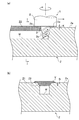
- FIG. 1A is a side sectional view
- FIG. 2B is a II longitudinal sectional view of FIG.
- A) is a side view which shows a 1st modification
- B) is a bottom view of the shoulder part which shows a 2nd modification. It is a side view which shows a 3rd modification.
- FIG. 12A is a sectional view taken along line III-III in FIG. 12A
- FIG. 12B is a sectional view taken along line III-III in FIG. 12B
- FIG. 12C is a sectional view taken along line III-III in FIG. It is. It is a graph which shows the relationship between the space
- Rotating tool for forming a gap used in the gap depth test where (a) is a tool NO.T2, (b) is a tool NO.T2-1, (c) is a side view of the tool NO.T2-2, A bottom view is shown.
- gap depth test Comprising: (a) And (b) shows the result of tool NO.T2, (c) and (d) shows the result of tool NO.T2-1.
- the gap forming rotary tool 1 includes a shoulder portion 2 and a stirring pin 3.
- the gap forming rotary tool 1 is made of, for example, tool steel.
- the gap forming rotary tool 1 is a tool for forming a tunnel-like gap inside a metal member by rotating and rotating the metal member.
- a metal member can be used as a cooling plate by flowing a fluid such as gas or liquid through a tunnel-shaped gap formed by this tool.
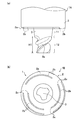
- the shoulder portion 2 has a cylindrical shape and is connected to a friction stirrer (not shown). On the bottom surface 2a of the shoulder portion 2, a ridge 2b is formed.
- the protrusion 2b is formed in a spiral around the stirring pin 3, as shown in FIG.
- the cross-sectional shape of the protrusion 2b is not particularly limited, but is rectangular in this embodiment.
- the number of windings of the ridge 2b is not particularly limited, but in the present embodiment, it is wound about one and a half times or more.
- the start position of the protrusion 2b (distance P1 from the base end of the stirring pin 3 to the start position of the protrusion 2b) and the scroll pitch of the protrusion 2b (distance P2 between the protrusions 2b) are not particularly limited. What is necessary is just to set suitably. Further, the protrusion 2b may not be provided.
- the stirring pin 3 is concentric with the shoulder portion 2 and is suspended from the bottom surface 2 a of the shoulder portion 2. Further, the stirring pin 3 is tapered in this embodiment.
- the length of the stirring pin 3 is not particularly limited and may be set as appropriate.
- a spiral groove 3 a is formed on the outer peripheral surface of the stirring pin 3 from the tip end to the base end of the stirring pin 3.
- the spiral groove 3a is formed by groove processing with a ball end mill.
- the cross-sectional shape of the spiral groove 3a is not particularly limited, but is a semicircle in the present embodiment.
- the spiral groove 3a is formed clockwise when it is traced downward from above (right screw).
- the angle (lead angle) ⁇ of the spiral groove 3a with respect to the reference plane with the axial direction of the stirring pin 3 as the normal is preferably set appropriately between 20 and 40 degrees.
- the angle ⁇ of the spiral groove 3a is less than 20 degrees, the angle is too shallow, and the plastic fluidized metal from the shoulder portion 2 is hardly scraped.
- the angle ⁇ of the spiral groove 3a is larger than 40 degrees, the length of the spiral groove 3a with respect to the stirring pin 3 is shortened, so that the plastic fluidized metal is hardly scraped out from the shoulder portion 2. Therefore, in any case, the voids tend to be crushed.
- the number of turns of the spiral groove 3a in the axial direction is not particularly limited, but it is preferable that the spiral groove 3a is wound at least once. If it is wound more than once, the gap can be formed larger. If the number of turns of the spiral groove 3a is less than one turn, the position of the spiral groove 3a with respect to the agitation pin 3 is biased, so that the plastic fluidized metal may remain on either side wall of the formed gap.
- the spiral groove 3a is configured as described above. However, the spiral groove 3a may be formed counterclockwise when traced from above to below (left-hand thread).
- the material of the metal member Z is not particularly limited, but may be selected from metals capable of friction stir, such as aluminum, aluminum alloy, copper, copper alloy, titanium, titanium alloy, magnesium, magnesium alloy.
- the gap forming rotary tool 1 is rotated above the metal member Z, the agitation pin 3 is pushed into the surface Za of the metal member Z, and the gap relative to the metal member Z is maintained at a constant height.
- the forming rotary tool 1 is moved.
- the rotational speed of the gap forming rotary tool 1 is not particularly limited, but is set to, for example, 700 to 1300 rpm.
- the moving speed of the gap forming rotary tool 1 is set, for example, between 200 and 400 mm / min.
- the bottom surface 2a of the shoulder portion 2 and the surface Za of the metal member Z may be moved while being in contact with each other, or may be moved with a gap.
- the gap (distance) K between the bottom surface 2a of the shoulder portion 2 and the surface Za of the metal member Z may be appropriately set, for example, between 0 and 3.0 mm.
- the gap is formed clockwise as viewed from above.
- the rotary tool 1 is rotated. That is, the gap forming rotary tool 1 is rotated and moved in a direction in which the metal plastically fluidized by the spiral groove 3a is scraped up onto the surface Za of the metal member Z.
- the gap forming rotary tool 1 is formed in the direction in which the plastic fluidized metal is wound up on the surface Za of the metal member Z, that is, counterclockwise. Rotate.
- the metal member Z is frictionally stirred by the gap forming rotary tool 1, and an upward plastic flow is generated by the spiral groove 3a.
- the fluidized metal is guided to the spiral groove 3a and scraped out to the surface Za side of the metal member Z.
- the scraped metal is pressed by the pressing force of the gap forming rotary tool 1 while being in contact with the bottom surface 2a.
- a tunnel-like gap M formed by scraping out the metal is formed on the trace where the gap-forming rotary tool 1 has passed, and a plasticized region Z2 is formed on the gap M.
- the metal member Z after the friction stir consists of a main body part Z1, a gap M formed inside the main body part Z1, and a plasticized region covering the upper part of the gap M.
- the plasticized region Z2 is a portion formed by hardening after the metal is plastic fluidized by friction stirring.
- the plasticized region Z2 has an inverted frustum shape in cross section and is formed so as to cover the space M.
- the plasticized region Z2 is formed by pressing the metal frictionally stirred by the stirring pin 3 by the bottom surface 2a of the shoulder portion 2.
- the metal overflowing from the bottom surface 2a of the shoulder portion 2 becomes a burr V and is exposed on the surface Za.
- the burr V is preferably removed by cutting or the like.
- the gap M is formed in a substantially rectangular shape in cross section in the present embodiment.
- the gap M is a sealed space, and no surface defects communicating with the gap M are formed in the plasticized region Z2 or in the boundary portion between the main body Z1 and the plasticized region Z2.
- the distance from the upper end of the gap M to the surface Za is defined as “gap depth D”.
- the gap M may be crushed without the metal being scraped suitably.
- the metal is scraped too much, and the plasticized region Z2 becomes thin, and surface defects communicating with the gap M are formed in the plasticized region Z2 or in the boundary portion between the main body Z1 and the plasticized region Z2.
- the metal is suitably scraped and the scraped metal can be pressed by the bottom surface 2 a of the shoulder portion 2, so that the gap M is not easily crushed and the metal member Z Difficult to make surface defects.
- the load given to the friction stirrer can be reduced.
- the conditions such as the ratio between the outer diameter X1 of the shoulder portion 2 and the outer diameter Y2 of the tip of the stirring pin 2 and the numerical value of the angle ⁇ of the spiral groove will be described in Examples.
- stirring pin 3 since the stirring pin 3 according to the present embodiment has a tapered shape, it is possible to reduce the press-fitting resistance when being pushed into the metal member Z.
- the gap forming rotary tool 1A according to the first modified example is different from the above-described embodiment in that the stirring pin 3 includes the flat surface portion 11 and the spiral groove portion 12.
- the outer peripheral surface of the stirring pin 3 according to the first modification has a flat surface portion 11 in which no groove is formed and a spiral groove portion 12 in which the spiral groove 3 a is formed.
- the outer peripheral surface of the flat surface portion 11 is flat and is formed from the base end of the stirring pin 3 to almost the center of the stirring pin 3.
- a spiral groove 3a is formed from the tip to almost the center (up to the flat surface portion 11).
- the spiral groove 3a is preferably wound at least once.
- the height H1 of the spiral groove portion 12 may be appropriately set according to the depth of the gap M to be formed with respect to the metal member Z.
- the height H1 is 30 to 70% with respect to the length of the stirring pin 3 (The height of the flat surface portion 11 is preferably 70% to 30% with respect to the length of the stirring pin 3).
- the metal is relatively easily scraped, and the gap depth D is relatively small (shallow).
- the rotation tool 1 ⁇ / b> A for gap formation according to the first modification the metal is scraped by the spiral groove portion 12 to form the gap M, but the metal that is frictionally stirred by the flat surface portion 11 is from the shoulder portion 2. Hard to be scraped to the outside. Accordingly, since the thickness of the plasticized region Z2 is increased, the gap depth D can be increased (deeply). As a result, a large gap M can be formed in a deep position of the metal member Z, and surface defects are less likely to be formed in the plasticized region Z2 or in the boundary portion between the main body Z1 and the plasticized region Z2.
- the protrusion 2b according to the second modification includes a plurality of notches 2c that divide the protrusion 2.
- the plastic fluidized metal passes through the notch portion 2c, so that the plastic fluidized metal flows easily in the radial direction of the bottom surface 2a of the shoulder portion 2.
- the metal tends to gather around the base end of the stirring pin 3, and the plastic fluidized metal is easily scraped out from the notch 2c.
- a relatively large gap M can be formed.
- the number and size of the notches 2c may be set as appropriate.
- the gap forming rotary tool 1 ⁇ / b> C according to the third modification differs from the above-described embodiment in that the outer diameter of the stirring pin 3 is constant.
- the outer diameter Y1 of the proximal end of the stirring pin 3 of the rotary tool 1C for forming a gap is equal to the outer diameter Y2 of the distal end.
- the outer diameter of the stirring pin 3 may be constant.
- the void forming method was performed by changing the shape, size, ratio, etc. of each element constituting the void forming rotary tool, and the formed voids were observed.
- the gap forming rotary tool is hereinafter simply referred to as “tool”.
- the cross-sectional shape of the spiral groove formed in the stirring pin has a semicircular shape, and its radius is 1.5 mm.
- the starting position of the ridge (distance P1 in FIG. 1B) was 3.0 mm, and the scroll pitch (distance P2 in FIG. 1B) was 2.5 mm.
- a rotated tool was inserted into the alloy plate and moved a predetermined distance.
- the rotation speed of the tool was basically 800 RPM, and in the air gap depth test, the influence of the rotation speed of the tool was investigated by performing frictional stirring even at 1275 RPM.
- the moving speed of the tool was 100 mm / min or 300 mm / min.
- the effect of the moving speed was also investigated by changing the moving speed between 50 and 300 mm / min.
- the gap from the surface of the metal member to the bottom surface of the shoulder portion was changed to 0 mm, 1.0 mm, 2.0 mm, and 3.0 mm to obtain a single
- the gaps formed by friction stirring on the metal members were compared.
- the central portion of the alloy plate was cut, polished and etched, and then the shape of the formed void was observed.
- gap formed using the imaging device was measured.
- ⁇ Spiral groove angle test> In the spiral groove angle test, the influence of the angle of the spiral groove 3a of the stirring pin 3 was investigated. As shown in FIG. 5, three types of tools Nos. S1 to S3 were used in this test. The angle of the spiral groove 3a with the horizontal plane was set to 40 degrees for tool No. S1, 30 degrees for tool NO. S2, and 20 degrees for tool NO. S3. Further, the number of turns of the spiral groove of each tool in the axial direction of the stirring pin 3 is about 0.8 lap for the tool NO.S1, about 1.3 lap for the tool NO.S2, and about 2.3 for the tool NO.S3. It is around.
- the configuration other than the angle of the spiral groove 3a is the same for all three types.
- the outer diameter of the shoulder portion 2 is 22 mm
- the outer diameter of the proximal end of the stirring pin 3 is 10 mm
- the outer diameter of the distal end is 7 mm
- the length was set to 11 mm.
- Each tool includes a spiral protrusion 2 b on the bottom surface 2 a of the shoulder portion 2.
- the height of the protrusion 2b was 1 mm.
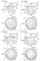
- FIG. 6 is a plan view of the metal member showing the test result of the spiral groove angle test, where (a) shows the result of tool NO.S1, (b) shows the result of tool NO.S2, and (c) shows the tool NO.
- the result of S3 is shown.
- four plasticized regions Z2 are formed on the surface Za of the metal member Z (main body portion Z1).
- the plasticized region Z2 is, in order from the top of the drawing, when the gap from the surface Za of the metal member Z to the bottom surface 2a of the shoulder portion 2 is 0 mm, 1.0 mm, 2.0 mm, 3.0 mm Shows the results of the case.
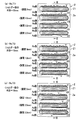
- 7A is a sectional view taken along the line II-II in FIG. 6A
- FIG. 7B is a sectional view taken along the line II-II in FIG. 6B
- FIG. 7C is a sectional view taken along the line II in FIG. FIG.
- the side where the moving speed of the tool is added to the rotational speed of the tool is “Advancingdvside” (hereinafter also referred to as “Ad side”), and the rotational speed of the tool is The side on which the moving speed is subtracted is referred to as “Retreating side” (hereinafter also referred to as “Re side”).
- Ad side the side where the moving speed of the tool is added to the rotational speed of the tool
- Re side The side on which the moving speed is subtracted
- the tool while the tool is rotated clockwise, the tool is moved from the left to the right in FIG. 6, so the left side in the traveling direction is the Ad side and the right side is the Re side.
- gap M in tool NO.S1 exhibits a vertically elongate rectangular shape.
- the plasticized region Z2 covers the gap M, but a part of the plasticized area Z2 remains on the Re side wall of the gap M.
- the gap M having substantially the same shape is formed under the condition of the gap 1.0 to 3.0, and the plastic fluidized metal is formed on the side wall of the gap M. It is discharged outside without remaining.
- the width of the formed gap M and the outer diameter of the tip of the stirring pin 2 were substantially equal, but in the tool NO. S1, the width of the formed gap was It was smaller than the outer diameter of the tip of the stirring pin 2.
- a part of the plasticized region Z2 remains on the side wall of the gap M on the Re side. This is considered to be caused by the angle and the number of windings of the spiral groove 3a of the NO.S1 tool.
- Tool No. S1 has a short spiral groove 3a with respect to the stirring pin 3 because the spiral groove 3a has a deep angle of 40 degrees. Therefore, it is considered that the plastic fluidized metal is difficult to be discharged. Moreover, in tool No. 1, since the number of turns of the spiral groove 3a is less than one turn, the position of the spiral groove 3a with respect to the stirring pin 3 is biased. For this reason, it is considered that the plasticized metal remains on one side wall (here, Re side) of the formed gap M.
- FIG. 8 is a graph showing the relationship between the gap area and the gap in the spiral groove angle test for each tool. As shown in FIGS. 7 and 8, the gap area of the gap M formed by the tool NO. S2 and the tool NO. S3 is substantially the same, but the gap area obtained by the tool NO. S1 is It was smaller than the void area of S2 and tool NO.S3.
- the gap area (the cross-sectional area of the gap M) increased as the gap increased with the tools No. S1 to S3.
- the increase rate of the void area was about 7 mm 2 / mm, which was almost the same as the outer diameter of the tip of the stirring pin 3.
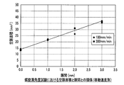
- FIG. 9 is a graph showing the relationship between the gap area and the gap in the spiral groove angle test for each moving speed. Since the tool Nos. S1 to S3 have substantially the same result, FIG. 9 shows the result of the tool No. S2 as a representative example.
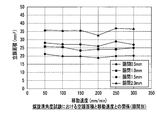
- FIG. 10 is a graph showing the relationship between the gap area and the moving speed in the spiral groove angle test for each gap. FIG. 10 shows the relationship between the gap area obtained with the tool No. S3 and the moving speed. As apparent from FIGS. 9 and 10, it was found that the gap area is not significantly affected by the change in the moving speed.
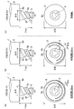
- ⁇ Shoulder outer diameter test> In the shoulder part outer diameter test, the influence of the outer diameter of the shoulder part 2 was investigated. As shown in FIG. 11, three types of tools NO. T1 to T3 were used in this test.
- the outer diameter of the shoulder portion 2 was set to 20 mm for tool NO. T1, 18 mm for tool NO. T2, and 16 mm for tool NO. T3.
- the configuration other than the outer diameter of the shoulder portion 2 is the same for all three types.
- the outer diameter of the base end of the stirring pin 3 is set to 10 mm, the outer diameter of the distal end is set to 7 mm, and the length of the stirring pin 3 is set to 11 mm.
- Each tool includes a spiral protrusion 2 b on the bottom surface 2 a of the shoulder portion 2. The height of the protrusion 2b was 1 mm.
- FIG. 12 is a plan view of the metal member showing the test result of the shoulder portion outer diameter test, where (a) shows the result of tool NO.T1, (b) shows the result of tool NO.T2, and (c) shows the tool.
- the result of NO.T3 is shown.
- 13A is a sectional view taken along line III-III in FIG. 12A
- FIG. 13B is a sectional view taken along line III-III in FIG. 12B
- FIG. 13C is a sectional view taken from FIG. It is III-III sectional drawing.
- the tool No. S3 described above has an outer diameter of the shoulder portion 2 of 22 mm, and the other configurations are the same as the tools NO. T1 to T3.
- the plastic fluidized metal comes into contact with the bottom surface 2a of the shoulder portion 2 and a large amount of burr V is discharged from the Re side. I understood.
- the gap is 3.0 mm, the burrs V are discharged on the Re side, but the surface defect E communicating with the gap M is formed by the lack of metal in the plasticized region Z2 in the tool NO.T1 and the tool NO.T3. .
- the height of the gap M increased as the outer diameter of the shoulder portion 2 became smaller.
- the metal pressed by the bottom surface 2a of the shoulder portion 2 is reduced. For this reason, it is considered that the plastic fluidized metal is easily scraped off, which leads to an increase in the height of the gap M.
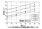
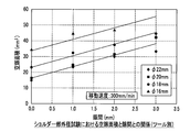
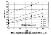
- FIG. 14 and 15 are graphs showing the relationship between the gap area and the gap in the shoulder portion outer diameter test for each tool.
- FIG. 14 shows the moving speed of 100 mm / min
- FIG. 15 shows the moving speed of 300 mm / min. The result when set to.
- the gap area increased as the gap increased in all tools.
- the void area of the void M can be increased.
- the increase ratio (inclination of increase) in the gap area was about 7 mm 2 / mm for both the tool No. S3 and the tool Nos. T1 to T3, which was the same as the outer diameter of the tip of the stirring pin 3.
- FIGS. 16 and 17 are graphs showing the relationship between the gap area and the outer diameter of the shoulder portion in the shoulder portion outer diameter test for each gap.
- FIG. 16 shows the moving speed at 100 mm / min
- FIG. 17 shows the moving speed. The result is shown when is set to 300 mm / min.
- the gap area obtained when the outer diameter of the shoulder portion 2 is 22 mm and the gap area obtained when the outer diameter of the shoulder portion 2 is 20 mm are as follows. It was almost equivalent. In the range where the outer diameter of the shoulder portion 2 is 20 mm to 16 mm, the void area increased as the outer diameter of the shoulder portion 2 decreased. The increase rate of the void area (inclination of increase) was about 5 mm 2 / mm.
- ⁇ Ridge test> In the ridge test, the influence of the ridge 2b formed on the bottom surface 2a of the shoulder portion 2 was investigated. As shown in FIG. 18, three types of gap forming rotary tool tools No. S3-1 to S3-3 were used in this test. The width of the notch 2c of the ridge 2b was set to 2 mm for the tool No. S3-1 and 6 mm for the tool No. S3-2. Tool No. S3-3 has no protrusions. The configuration other than the protrusion 2b is the same for all three types. The outer diameter of the shoulder portion 2 is 22 mm, the outer diameter of the proximal end of the stirring pin 3 is 10 mm, the outer diameter of the distal end is 7 mm, and the length of the stirring pin is It was set to 11 mm.
- FIG. 19 is a cross-sectional view of the metal member showing the test result of the ridge test, where (a) is the result of the tool No. S3-1, (b) is the result of the tool NO. S3-2, (c) Indicates the result of tool No. S3-3.
- FIG. 20 is a graph showing the relationship between the gap area and the gap in the ridge test for each tool. As shown in FIG. 5 (c), the above-described gap forming rotating tool tool NO.S3 is provided with a protrusion 2b without a notch 2c, and the other structure is a tool NO.S3-1. Since this is equivalent to S3-3, the comparison will be made also with FIG. 6C and FIG. 7C.
- the tool NO. 3, tool NO. 3-1, and tool NO. 3-3 have substantially the same gap area. Comparing the results of Tool No. 3 with the results of Tool No. 3-3, it was found that the presence or absence of the protrusion 2b had no effect on the result of the gap area. However, comparing (c) of FIG. 7 and (c) of FIG. 19, it has been found that the shape of the gap M of the tool No. 3 having the protrusions 2b is better. This is considered to be due to the fact that the plastic fluidized metal tends to gather around the base end side of the stirring pin 3 due to the protrusion 2b.
- the configuration other than the outer diameter of the stirring pin 3 is the same for all four types, the outer diameter of the shoulder portion 2 is set to 22 mm, and the length of the stirring pin 3 is set to 11 mm.
- Each tool includes a spiral protrusion 2 b on the bottom surface 2 a of the shoulder portion 2. The height of the protrusion 2b was 1 mm.
- increasing rate (slope of the graph) of the void area of the tool NO.U1 increase the percentage of void area of 10 mm 2 / mm, in FIG. 24 10.7 mm 2 / mm, tool NO.U2 in Figure 23 In Figure 23 12.6 mm 2 / mm, Figure 24 in 12.5 mm 2 / mm, increasing the proportion of the void area of the tool NO.U3 was 23 at 13.7 mm 2 / mm, in FIG. 24 14.4 mm 2 / mm . It is considered that when the gap is increased by 1 mm in each tool, the gap M is increased by the outer diameter of the stirring pin 3, so that the formed gap area is also increased by the outer diameter of the stirring pin 3.
- ⁇ Cavity depth test> In the gap depth test, as shown in FIG. 3A, the depth position of the gap M to be formed is determined by using a gap forming rotary tool having a flat surface portion 11 in which the spiral groove 3a is not formed. investigated. As shown in FIG. 26, three types of gap forming rotary tools were used in this test. Tool NO. T2 is a comparative example and is equivalent to the tool shown in FIG.
- the height of the spiral groove 12 of the tool NO. T2 is equal to the length of the stirring pin 3 and is 11.0 mm.
- the height of the flat surface portion 11 of the tool NO. T2-1 is 3.5 mm, and the height of the spiral groove portion 12 is 7.5 mm.
- the flat surface portion 11 of the tool NO. T2-2 has a height of 6.0 mm, and the spiral groove portion 12 has a height of 5.0 mm.
- the configuration other than the height of the spiral groove portion 12 is the same for all three types.
- the outer diameter of the shoulder portion 2 is 18 mm
- the outer diameter of the proximal end of the stirring pin 3 is 10 mm
- the outer diameter of the distal end is 7 mm.
- All of the tools are provided with a spiral protrusion 2b on the bottom surface 2a of the shoulder portion 2.
- the height of the protrusion 2b was 1 mm.
- the gaps from the surface Za of the metal member Z to the bottom surface 2a of the shoulder portion 2 were set to three types: 0 mm, 1.0 mm, and 2.0 mm.
- each tool was tested at two types of rotation speeds of 800 RPM and 1275 RPM.
- FIG. 27 is a cross-sectional view showing the test results of the void depth test, where (a) and (b) are the results of tool NO.T2, and (c) and (d) are the results of tool NO.T2-1.
- Indicates. 28 is a cross-sectional view showing the test results of the void depth test, and (a) and (b) show the results of the tool No. T2-2.
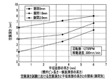
- FIG. 29 is a graph showing the relationship between the gap depth and the height of the flat surface portion in the gap depth test for each gap.
- FIG. 30 is a graph showing the relationship between the gap depth and the height of the flat surface portion in the gap depth test for each gap. 29 and 30 are different in the rotation speed of the tool, the rotation speed of the test according to FIG. 29 is 800 RPM, and the rotation speed of the test according to FIG. 30 is 1275 RPM.
- the gap depth D increases as the height of the flat surface portion 11 (the length of the stirring pin 3 ⁇ the height of the spiral groove portion 12) increases. Moreover, it turned out that the space
- FIG. 29 and FIG. 30 are compared, it is found that the gap depth D is slightly increased when the rotational speed of the tool is higher.
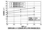
- FIG. 31 is a graph showing the relationship between the gap area and the gap in the gap depth test according to the height of the spiral groove.
- FIG. 32 is a graph showing the relationship between the gap area and the gap in the gap depth test according to the height of the spiral groove.
- FIG. 31 and FIG. 32 are different in the rotation speed of the tool, the rotation speed of the test according to FIG. 31 is 800 RPM, and the rotation speed of the test according to FIG. 32 is 1275 RPM.
- FIGS. 31 and 32 and FIGS. 27 and 28 it has been found that the gap area increases as the height of the spiral groove portion 11 increases. Comparing FIG. 31 with FIG. 32, it was found that the number of rotations of the tool had almost no effect on the increase or decrease of the gap area. From the above, according to the gap test, it was found that the gap M can be formed at a deep position when the height of the flat surface portion 11 is increased. On the other hand, it was found that when the height of the flat surface portion 11 is excessively increased, the void area of the void M is decreased.
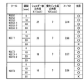
- FIG. 33 and FIG. 34 are tables showing the status of each tool and the formed gap in the example. “ ⁇ ” in the “situation” item indicates that the state of the void M is good, and “x” indicates a state in which the surface defect E is generated.
Landscapes
- Engineering & Computer Science (AREA)
- Mechanical Engineering (AREA)
- Pressure Welding/Diffusion-Bonding (AREA)
Abstract
Description
なお、螺旋溝3aは、本実施形態では、前記したように構成したが、上方から下方にたどったときに左回りに形成してもよい(左ネジ)。
しかし、空隙形成用回転ツール1によれば、金属を好適に掻き出すとともに、掻き出された金属をショルダー部2の底面2aで押さえることができるため、空隙Mが潰れにくく、かつ、金属部材Zに表面欠陥ができにくい。また、摩擦攪拌装置に与える負荷を軽減することができる。ショルダー部2の外径X1と攪拌ピン2の先端の外径Y2との比率や螺旋溝の角度αの数値等の条件については実施例で述べる。
次に、本発明の第一変形例について説明する。第一変形例に係る空隙形成用回転ツール1Aでは、攪拌ピン3に平坦面部11と螺旋溝部12とを備えている点で前記した実施形態と相違する。
しかし、第一変形例に係る空隙形成用回転ツール1Aによれば、螺旋溝部12によって金属が掻き出されて空隙Mが形成されるが、平坦面部11で摩擦攪拌される金属はショルダー部2から外部に掻き出されにくい。したがって、塑性化領域Z2の厚みが大きくなるため、空隙深さDを大きく(深く)することができる。これにより、金属部材Zの深い位置に大きな空隙Mを形成することができるとともに、塑性化領域Z2の内部や、本体部Z1と塑性化領域Z2との境界部分に表面欠陥がより形成されにくい。
次に、本発明の第二変形例について説明する。図3の(b)に示すように、第二変形例に係る空隙形成用回転ツール1Bでは、ショルダー部2の底面2aに形成された突条2bが断続的に形成されている点で前記した実施形態と相違する。
次に、本発明の第三変形例について説明する。図4に示すように、第三変形例に係る空隙形成用回転ツール1Cでは、攪拌ピン3の外径が一定である点で前記した実施形態と相違する。
次に、本発明の実施例について説明する。実施例では、空隙形成用回転ツールを構成する各要素の形状、大きさ、比率等を変化させて空隙形成方法を行い、形成された空隙を観察した。なお、説明の便宜上、空隙形成用回転ツールを以下単に「ツール」ともいう。
螺旋溝角度試験では、攪拌ピン3の螺旋溝3aの角度の影響を調査した。図5に示すように、この試験では三種類のツールNO.S1~S3を使用した。螺旋溝3aの水平面との角度を、ツールNO.S1では40度、ツールNO.S2では30度、ツールNO.S3では20度に設定した。また、各ツールの螺旋溝の攪拌ピン3の軸方向に対する巻回数は、ツールNO.S1では約0.8周、ツールNO.S2では約1.3周、ツールNO.S3では約2.3周になっている。
図7の(a)は、図6の(a)のII-II断面図、(b)は図6の(b)のII-II断面図、(c)は図6の(c)のII-II断面図である。
一方、ツールNO.S2及びツールNO.S3において、隙間1.0~3.0の条件では、略同一形状の空隙Mが形成されており、空隙Mの側壁には塑性流動化された金属が残存せずに、外部に排出されている。
図10は、螺旋溝角度試験における空隙面積と移動速度との関係を隙間別に示したグラフである。図10では、ツールNO.S3で得られた空隙面積と移動速度との関係を示している。
図9及び図10から明らかなように、空隙面積は、移動速度の変化によってはさほど影響を受けないことがわかった。
ショルダー部外径試験では、ショルダー部2の外径の影響を調査した。図11に示すように、この試験では三種類のツールNO.T1~T3を使用した。ショルダー部2の外径を、ツールNO.T1では20mm、ツールNO.T2では18mm、ツールNO.T3では16mmに設定した。ショルダー部2の外径以外の構成は、三種類とも同等であって、攪拌ピン3の基端の外径は10mm、先端の外径は7mm、攪拌ピン3の長さは11mmに設定した。また、いずれのツールもショルダー部2の底面2aに、渦巻き状の突条2bを備えている。突条2bの高さは1mmとした。
一方、図17に示すように、移動速度が300mm/minの条件で隙間3.0mmの条件では、ショルダー部2の外径が16mm、18mmで塑性化領域に表面欠陥が発生したので空隙面積が減少した。
突条試験では、ショルダー部2の底面2aに形成された突条2bの影響を調査した。図18に示すように、この試験では三種類の空隙形成用回転ツールツールNO.S3-1~S3-3を使用した。突条2bの切欠き部2cの幅を、ツールNO.S3-1では2mm、ツールNO.S3-2では6mmに設定した。ツールNO.S3-3では突条を設けていない。突条2b以外の構成は、三種類とも同等であって、ショルダー部2の外径は22mm、攪拌ピン3の基端の外径は10mm、先端の外径は7mm、攪拌ピンの長さは11mmに設定した。
攪拌ピン外径試験では、同一の外径のショルダー部2を用いるとともに、攪拌ピン3の基端から先端までの外径は一定となるように設定し、各攪拌ピン3の外径を変化させて攪拌ピン3の外径の影響を調査した。図21に示すように、この試験では4種類の空隙形成用回転ツールツールNO.U1~U4を使用した。攪拌ピン3の外径を、ツールNO.U1では10mm、ツールNO.U2では12mm、ツールNO.U3では14mm、ツールNO.U4では16mmに設定した。攪拌ピン3の外径以外の構成は、四種類とも同等であって、ショルダー部2の外径は22mm、攪拌ピン3の長さは11mmに設定した。また、いずれのツールもショルダー部2の底面2aに、渦巻き状の突条2bを備えている。突条2bの高さは1mmとした。
空隙深さ試験では、図3の(a)に示すように、螺旋溝3aが形成されていない平坦面部11を備えた空隙形成用回転ツールを用いて、形成される空隙Mの深さ位置を調査した。図26に示すように、この試験では3種類の空隙形成用回転ツールを使用した。ツールNO.T2は、比較例であって図11の(b)で示すツールと同等である。
以上より、空隙試験によると、平坦面部11の高さを大きくすると、空隙Mを深い位置に形成することができることがわかった。一方、平坦面部11の高さを大きくしすぎると、空隙Mの空隙面積が小さくなってしまうことがわかった。
図33及び図34は、実施例における各ツールと形成された空隙の状況とを現した表である。「状況」の項目の「○」は空隙Mの状態が良好を示し、「×」は表面欠陥Eが発生している状態を示す。
2 ショルダー部
2a 底面
2b 突条
2c 切欠き部
3 攪拌ピン
3a 螺旋溝
D 空隙深さ
K 隙間
M 空隙
V バリ
Z 金属部材
Z1 本体部
Z2 塑性化領域
Za 表面
Claims (9)
- 摩擦攪拌によって金属部材の内部に空隙を形成する際に使用される空隙形成用回転ツールであって、
ショルダー部とこのショルダー部から垂下する攪拌ピンとを有し、
前記攪拌ピンの外周面には螺旋溝が刻設されており、
前記ショルダー部の外径を前記攪拌ピンの先端の外径で除した値が1.4以上2.2以下であることを特徴とする空隙形成用回転ツール。 - 前記攪拌ピンの軸方向を法線とする基準面に対する前記螺旋溝の角度が20度以上40度以下であることを特徴とする請求の範囲第1項に記載の空隙形成用回転ツール。
- 前記螺旋溝は、前記攪拌ピンに一周以上巻き回されていることを特徴とする請求の範囲第1項に記載の空隙形成用回転ツール。
- 前記攪拌ピンは、前記螺旋溝が形成された螺旋溝部と前記螺旋溝が形成されていない平坦面部とを備えており、
前記螺旋溝部は、前記攪拌ピンの先端から刻設されていることを特徴とする請求の範囲第1項に記載の空隙形成用回転ツール。 - 前記ショルダー部の底面に突条が突設されており、
前記突条は、前記攪拌ピンの周囲に渦巻き状に形成されていることを特徴とする請求の範囲第1項に記載の空隙形成用回転ツール。 - 前記突条には、前記ショルダー部の底面の半径方向に切り欠かれた切欠き部が形成されていることを特徴とする請求の範囲第5項に記載の空隙形成用回転ツール。
- 前記攪拌ピンは、先端から基端まで一定の外径からなることを特徴とする請求の範囲第1項に記載の空隙形成用回転ツール。
- 空隙形成用回転ツールを用いて金属部材の内部に空隙を形成する空隙形成方法であって、
前記空隙形成用回転ツールは、
ショルダー部とこのショルダー部から垂下する攪拌ピンとを有し、
前記攪拌ピンの外周面には螺旋溝が刻設されており、
前記ショルダー部の外径を前記攪拌ピンの先端の外径で除した値が1.4以上2.2以下であり、
前記空隙形成用回転ツールを回転させつつ、前記金属部材に対して相対的に移動させる際に、摩擦攪拌によって流動化された金属が、前記螺旋溝によって前記金属部材の表面に掻き上げられる方向に前記空隙形成用回転ツールを回転させることを特徴とする空隙形成方法。 - 前記金属部材の表面と前記ショルダー部の底面との距離を0~3.0mmに設定することを特徴とする請求の範囲第8項に記載の空隙形成方法。
Priority Applications (3)
| Application Number | Priority Date | Filing Date | Title |
|---|---|---|---|
| KR1020137002922A KR20130036064A (ko) | 2010-07-12 | 2011-06-29 | 공극 형성용 회전 툴 및 공극 형성 방법 |
| KR1020147028915A KR20140131596A (ko) | 2010-07-12 | 2011-06-29 | 공극 형성 방법 |
| CN201180032907.0A CN102971108B (zh) | 2010-07-12 | 2011-06-29 | 空隙形成用旋转工具及空隙形成方法 |
Applications Claiming Priority (2)
| Application Number | Priority Date | Filing Date | Title |
|---|---|---|---|
| JP2010157499A JP5644217B2 (ja) | 2010-07-12 | 2010-07-12 | 空隙形成用回転ツール及び空隙形成方法 |
| JP2010-157499 | 2010-07-12 |
Publications (1)
| Publication Number | Publication Date |
|---|---|
| WO2012008307A1 true WO2012008307A1 (ja) | 2012-01-19 |
Family
ID=45469312
Family Applications (1)
| Application Number | Title | Priority Date | Filing Date |
|---|---|---|---|
| PCT/JP2011/064934 Ceased WO2012008307A1 (ja) | 2010-07-12 | 2011-06-29 | 空隙形成用回転ツール及び空隙形成方法 |
Country Status (5)
| Country | Link |
|---|---|
| JP (1) | JP5644217B2 (ja) |
| KR (2) | KR20140131596A (ja) |
| CN (1) | CN102971108B (ja) |
| TW (1) | TWI468247B (ja) |
| WO (1) | WO2012008307A1 (ja) |
Families Citing this family (13)
| Publication number | Priority date | Publication date | Assignee | Title |
|---|---|---|---|---|
| JP5574947B2 (ja) * | 2010-12-27 | 2014-08-20 | 三菱重工業株式会社 | 中空構造形成方法及び中空構造体 |
| KR20170002686A (ko) | 2011-08-19 | 2017-01-06 | 니폰게이긴조쿠가부시키가이샤 | 마찰 교반 접합 방법 |
| WO2013043877A1 (en) * | 2011-09-23 | 2013-03-28 | Burford Dwight A | Mandrel tool probe for friction stir welding |
| JP2014094409A (ja) | 2012-10-10 | 2014-05-22 | Nippon Light Metal Co Ltd | 伝熱板の製造方法及び摩擦攪拌接合方法 |
| JP6057840B2 (ja) * | 2013-06-11 | 2017-01-11 | 京浜ラムテック株式会社 | 内部空間形成方法、内部空間形成装置及び伝熱板 |
| JP6052232B2 (ja) * | 2014-01-27 | 2016-12-27 | 日本軽金属株式会社 | 接合方法 |
| JP5954472B2 (ja) * | 2015-07-10 | 2016-07-20 | 日本軽金属株式会社 | 空隙形成方法 |
| JP6103086B2 (ja) * | 2016-02-01 | 2017-03-29 | 日本軽金属株式会社 | 空隙形成方法 |
| TWI702102B (zh) * | 2019-01-25 | 2020-08-21 | 莊文茂 | 攪拌摩擦銲接裝置及其方法 |
| CN114555274B (zh) * | 2019-10-08 | 2024-07-26 | 山崎马扎克公司 | 搅拌销、摩擦搅拌接合用工具以及机床 |
| CN115647562B (zh) * | 2022-11-04 | 2023-06-23 | 哈尔滨工业大学 | 一种搅拌摩擦隧道成形装置及方法 |
| KR102567656B1 (ko) * | 2023-01-17 | 2023-08-17 | 성진엔테크(주) | 동종 및 다종 재료 마찰교반용접용 서브머지드 툴 조립체 |
| CN117139816B (zh) * | 2023-09-10 | 2026-04-28 | 哈尔滨工业大学(威海) | 一种基于超声辅助的搅拌摩擦隧道成形装置及工艺 |
Citations (13)
| Publication number | Priority date | Publication date | Assignee | Title |
|---|---|---|---|---|
| JPH1147961A (ja) * | 1997-08-04 | 1999-02-23 | Showa Alum Corp | プレート型ヒートパイプの製造方法 |
| JP2001347361A (ja) * | 2000-06-08 | 2001-12-18 | Mazda Motor Corp | 金属部材の表面処理方法 |
| JP2002001552A (ja) * | 2000-06-19 | 2002-01-08 | Kawasaki Heavy Ind Ltd | 摩擦撹拌接合の補修方法 |
| JP2002096158A (ja) * | 2000-09-21 | 2002-04-02 | Nippon Light Metal Co Ltd | 鋳物表面の微細空隙除去方法およびこれに用いる攪拌ツール |
| JP2003048083A (ja) * | 2001-08-01 | 2003-02-18 | Mazda Motor Corp | 回転工具、当該回転工具を用いた部材の処理方法及び表面処理方法 |
| JP2003136256A (ja) * | 2001-10-31 | 2003-05-14 | Mazda Motor Corp | 摩擦攪拌用回転工具及びそれを用いた処理方法 |
| JP2003225778A (ja) * | 2002-01-30 | 2003-08-12 | Nippon Light Metal Co Ltd | 摩擦撹拌接合方法およびこの方法に用いる摩擦撹拌ツール |
| JP2003326371A (ja) * | 2002-05-09 | 2003-11-18 | Mitsubishi Heavy Ind Ltd | 摩擦攪拌接合用工具 |
| JP2004522591A (ja) * | 2001-05-11 | 2004-07-29 | スヴェンスク ケルンブレンスレハンテリング アクチボラゲット | 摩擦攪拌溶接工具 |
| JP2006043730A (ja) * | 2004-08-04 | 2006-02-16 | Honda Motor Co Ltd | 摩擦撹拌接合方法 |
| JP2008162280A (ja) * | 2006-12-29 | 2008-07-17 | General Electric Co <Ge> | 繊維強化熱可塑性樹脂摩擦攪拌接合 |
| JP2009106978A (ja) * | 2007-10-30 | 2009-05-21 | Hitachi Ltd | 摩擦攪拌接合による補修方法 |
| JP2010253534A (ja) * | 2009-04-28 | 2010-11-11 | Osg Corp | 冷却路内蔵部材および冷却路内蔵部材の製造方法 |
Family Cites Families (3)
| Publication number | Priority date | Publication date | Assignee | Title |
|---|---|---|---|---|
| JP5092333B2 (ja) * | 2006-10-02 | 2012-12-05 | 日本軽金属株式会社 | 接合方法 |
| CN100519044C (zh) * | 2007-11-13 | 2009-07-29 | 江苏科技大学 | 一种搅拌摩擦焊的焊具 |
| CN101559533A (zh) * | 2009-05-18 | 2009-10-21 | 北京科技大学 | 一种分体式搅拌摩擦焊搅拌头 |
-
2010
- 2010-07-12 JP JP2010157499A patent/JP5644217B2/ja active Active
-
2011
- 2011-06-29 KR KR1020147028915A patent/KR20140131596A/ko not_active Ceased
- 2011-06-29 CN CN201180032907.0A patent/CN102971108B/zh active Active
- 2011-06-29 KR KR1020137002922A patent/KR20130036064A/ko not_active Ceased
- 2011-06-29 WO PCT/JP2011/064934 patent/WO2012008307A1/ja not_active Ceased
- 2011-07-11 TW TW100124488A patent/TWI468247B/zh active
Patent Citations (13)
| Publication number | Priority date | Publication date | Assignee | Title |
|---|---|---|---|---|
| JPH1147961A (ja) * | 1997-08-04 | 1999-02-23 | Showa Alum Corp | プレート型ヒートパイプの製造方法 |
| JP2001347361A (ja) * | 2000-06-08 | 2001-12-18 | Mazda Motor Corp | 金属部材の表面処理方法 |
| JP2002001552A (ja) * | 2000-06-19 | 2002-01-08 | Kawasaki Heavy Ind Ltd | 摩擦撹拌接合の補修方法 |
| JP2002096158A (ja) * | 2000-09-21 | 2002-04-02 | Nippon Light Metal Co Ltd | 鋳物表面の微細空隙除去方法およびこれに用いる攪拌ツール |
| JP2004522591A (ja) * | 2001-05-11 | 2004-07-29 | スヴェンスク ケルンブレンスレハンテリング アクチボラゲット | 摩擦攪拌溶接工具 |
| JP2003048083A (ja) * | 2001-08-01 | 2003-02-18 | Mazda Motor Corp | 回転工具、当該回転工具を用いた部材の処理方法及び表面処理方法 |
| JP2003136256A (ja) * | 2001-10-31 | 2003-05-14 | Mazda Motor Corp | 摩擦攪拌用回転工具及びそれを用いた処理方法 |
| JP2003225778A (ja) * | 2002-01-30 | 2003-08-12 | Nippon Light Metal Co Ltd | 摩擦撹拌接合方法およびこの方法に用いる摩擦撹拌ツール |
| JP2003326371A (ja) * | 2002-05-09 | 2003-11-18 | Mitsubishi Heavy Ind Ltd | 摩擦攪拌接合用工具 |
| JP2006043730A (ja) * | 2004-08-04 | 2006-02-16 | Honda Motor Co Ltd | 摩擦撹拌接合方法 |
| JP2008162280A (ja) * | 2006-12-29 | 2008-07-17 | General Electric Co <Ge> | 繊維強化熱可塑性樹脂摩擦攪拌接合 |
| JP2009106978A (ja) * | 2007-10-30 | 2009-05-21 | Hitachi Ltd | 摩擦攪拌接合による補修方法 |
| JP2010253534A (ja) * | 2009-04-28 | 2010-11-11 | Osg Corp | 冷却路内蔵部材および冷却路内蔵部材の製造方法 |
Also Published As
| Publication number | Publication date |
|---|---|
| CN102971108A (zh) | 2013-03-13 |
| CN102971108B (zh) | 2015-05-27 |
| JP2012020288A (ja) | 2012-02-02 |
| TWI468247B (zh) | 2015-01-11 |
| KR20130036064A (ko) | 2013-04-09 |
| TW201217090A (en) | 2012-05-01 |
| KR20140131596A (ko) | 2014-11-13 |
| JP5644217B2 (ja) | 2014-12-24 |
Similar Documents
| Publication | Publication Date | Title |
|---|---|---|
| JP5644217B2 (ja) | 空隙形成用回転ツール及び空隙形成方法 | |
| JP5954472B2 (ja) | 空隙形成方法 | |
| JP2016215264A (ja) | 摩擦撹拌接合工具、および摩擦撹拌接合装置 | |
| JP6119904B2 (ja) | 空隙形成用回転ツール及び空隙形成方法 | |
| JP2010520064A (ja) | 球面フライス | |
| JP5874794B2 (ja) | 空隙形成方法 | |
| CN102665583A (zh) | 螺丝制造方法、旋风切削刀具和螺丝制造机 | |
| JP2008539387A (ja) | 車輪軸受装置 | |
| JP6103086B2 (ja) | 空隙形成方法 | |
| EP2889501B1 (en) | Tapered roller bearing | |
| CN100470066C (zh) | 动压轴承 | |
| JP6451940B2 (ja) | 摩擦攪拌用工具及び摩擦攪拌用工具を用いた摩擦攪拌接合方法 | |
| KR101849445B1 (ko) | 나사 절삭용 탭 | |
| JP6964840B2 (ja) | 摩擦攪拌接合用回転工具及び摩擦攪拌接合方法 | |
| JP2017196694A (ja) | エンドミル | |
| JP3147239U (ja) | 切削具 | |
| JP5059337B2 (ja) | 鋳造物の組織改質方法 | |
| JP2015217748A (ja) | ボールジョイント、および、このジョイントを有するステアリング装置 | |
| JP2008275019A (ja) | 流体軸受の製造方法 | |
| JP4893133B2 (ja) | リターンチューブ、及びボールねじ | |
| JP5772586B2 (ja) | ボールねじ用ナット | |
| JP7685918B2 (ja) | ギヤの潤滑油量算出方法 | |
| JP2013249887A (ja) | ボールねじ装置 | |
| JP4831453B2 (ja) | フォーミング用工具 | |
| JP2009030809A (ja) | ボールねじ |
Legal Events
| Date | Code | Title | Description |
|---|---|---|---|
| WWE | Wipo information: entry into national phase |
Ref document number: 201180032907.0 Country of ref document: CN |
|
| 121 | Ep: the epo has been informed by wipo that ep was designated in this application |
Ref document number: 11806637 Country of ref document: EP Kind code of ref document: A1 |
|
| WWE | Wipo information: entry into national phase |
Ref document number: 1201006797 Country of ref document: TH |
|
| NENP | Non-entry into the national phase |
Ref country code: DE |
|
| ENP | Entry into the national phase |
Ref document number: 20137002922 Country of ref document: KR Kind code of ref document: A |
|
| 122 | Ep: pct application non-entry in european phase |
Ref document number: 11806637 Country of ref document: EP Kind code of ref document: A1 |