WO2012005197A1 - 鋼管杭及びその施工方法 - Google Patents
鋼管杭及びその施工方法 Download PDFInfo
- Publication number
- WO2012005197A1 WO2012005197A1 PCT/JP2011/065218 JP2011065218W WO2012005197A1 WO 2012005197 A1 WO2012005197 A1 WO 2012005197A1 JP 2011065218 W JP2011065218 W JP 2011065218W WO 2012005197 A1 WO2012005197 A1 WO 2012005197A1
- Authority
- WO
- WIPO (PCT)
- Prior art keywords
- steel pipe
- pipe pile
- pile
- protrusion
- tip
- Prior art date
- Legal status (The legal status is an assumption and is not a legal conclusion. Google has not performed a legal analysis and makes no representation as to the accuracy of the status listed.)
- Ceased
Links
Images


















Classifications
-
- E—FIXED CONSTRUCTIONS
- E02—HYDRAULIC ENGINEERING; FOUNDATIONS; SOIL SHIFTING
- E02D—FOUNDATIONS; EXCAVATIONS; EMBANKMENTS; UNDERGROUND OR UNDERWATER STRUCTURES
- E02D5/00—Bulkheads, piles, or other structural elements specially adapted to foundation engineering
- E02D5/66—Mould-pipes or other moulds
- E02D5/665—Mould-pipes or other moulds for making piles
Definitions
- the present invention relates to a steel pipe pile used in the field of civil engineering and architecture, such as a harbor structure or a bridge foundation or a building foundation, and a construction method thereof.
- This application claims priority based on Japanese Patent Application No. 2010-153290 filed in Japan on July 05, 2010, the contents of which are incorporated herein by reference.
- the outer peripheral surface of the tip of the pile is a tapered outer peripheral surface, or the outer peripheral surface of the entire length of the pile is a tapered outer peripheral surface, and the tip of the pile
- a reinforcing bar is spirally wound over the entire length of a constant diameter portion having a constant outer diameter from the taper portion (see, for example, Patent Document 1).
- Such a friction pile is expected to have a frictional force on the outer peripheral surface of the pile.
- a plurality of spiral wings are provided on the outer peripheral surface of the intermediate portion in the length direction of the pile at intervals in the pile axis direction, and the same pitch as the blade pitch (propulsion pitch) in the spiral wings is provided at the cone portion at the tip of the pile. It is also known that a steel strip is fixed to the cone portion spirally at the same propulsion pitch by welding or the like (see, for example, Patent Document 2).
- the pushing force refers to the force applied to push the pile down in the penetration direction.
- rotational force refers to the force applied in order to turn a pile.
- a reaction force is required to secure the pushing force to rotationally press the pile, and it is necessary to install a counterweight or an anchor on the rotational press-fitting machine to ensure the reaction force. It becomes.
- the rotary press-fitting construction machine is also increased in capacity and increased in size, so that the pile construction cost is further increased. Furthermore, in order to acquire the propulsive force of the pile, if a jig such as a spiral wing or blade for propulsion is attached to the pile, processing costs, mounting costs and material costs are incurred. Furthermore, in the construction of soft ground, Conversely, the construction speed is limited by the spacing between the spiral blades or blades, leading to a reduction in construction speed. Moreover, after penetrating an existing pile into a support layer, in order to acquire a higher support force, there exists a construction method which obstruct
- reaction force is usually obtained by the weight of the weight or the construction machine itself at the time of pile press-fitting construction, and in order to increase the reaction force, many weights are required, which is uneconomical.
- the force in the rotation direction can be obtained by applying the reaction force to another heavy machine with a rod-shaped jig or the like for obtaining the reaction force.
- the tip tapered portion makes a high load on the tapered portion because the tip tapered portion comes into direct contact with the ground at the time of pile construction.
- An object of this invention is to provide the steel pipe pile which can reduce the pushing force of a pile, and its construction method.
- a steel pipe pile according to one aspect of the present invention is a steel pipe pile that is open and hollow at the front end in the excavation direction, and has a constant diameter portion having a constant outer diameter, and toward the front end.
- a tip portion having an inner shape dimension and an outer shape dimension that gradually decrease; extending partially or entirely on the outer peripheral surface of the tip portion from the front end toward the rear end, and radially outward of the tip portion A protrusion protruding in the direction is provided.
- the protrusion is inclined so that the rear end side of the protrusion is behind the constant diameter portion and the tip end in the rotation direction. It is preferable.
- the protrusion is disposed to be inclined in the circumferential direction with respect to the central axis of the tip, and a surface perpendicular to the central axis and the protrusion The angle formed with the central axis in the extending direction is preferably 20 ° to 70 °.
- the protrusion is positioned so that the protrusion is positioned on the inner side in the radial direction of the tip portion than the outer dimension of the constant diameter portion. The height is preferably defined.
- the steel pipe pile according to (2) above it is preferable that a plurality of excavation bits are provided at intervals in the circumferential direction of the front end. (7) In the steel pipe pile according to (6), it is preferable that the lower end of the protrusion is located immediately above the upper surface of the excavation bit. (8) In the steel pipe pile according to (6), it is preferable that the excavation bit is disposed on the inner side in the radial direction of the tip portion than the outer dimension of the constant diameter portion. (9) In the steel pipe pile described in (1) above, the ratio of the height dimension in the length direction of the tip portion to the outer dimension of the constant diameter portion is preferably 0.3 to 5.5.
- a ratio of an outer diameter dimension of the front end to an outer diameter dimension of the constant diameter portion is preferably 0.60 to 0.95.
- the tip portion is provided with a pointed portion protruding from the front end and sharpened in the excavation direction.
- steel pipe piles include a closed-end pile whose front end is closed and an open-end pile whose front end is open, and the present invention belongs to an open-end pile whose front end is open.
- the steel pile pile is supported by the friction pile that is expected to provide the support force by mainly exerting the frictional force on the peripheral surface without being driven into the support layer, and the support force at the tip portion is driven mainly by being driven into the support layer.
- There is a support pile that expects a force and the present invention belongs to a support pile that expects a support force by driving a steel pipe pile into a support layer to exhibit a support force at the tip.
- the pile is installed in the ground by the projection with a simple configuration in which the projection is simply provided at the tapered tip portion where the inner and outer dimensions are gradually reduced.
- wear and deformation of the tip can be suppressed.
- the construction machine can be downsized and the steel pipe pile can be made at a low construction cost.
- tip part is a taper shape, this steel pipe pile can reduce the resistance by the friction of an internal peripheral surface, and can aim at the improvement of workability.
- the tapered tip increases the projected area of the bottom surface of the pile and resists the ground, so a high supporting force can be easily obtained.
- a high compression load can be borne at the tapered tip (bottom projected area).
- the steel pipe pile (the steel pipe pile having only the constant-diameter portion) having a higher supporting force can be exhibited. Usually, it is necessary to block the front end of the pile in order to exert a supporting force at the front end of the pile, such as a driven pile.
- a plurality of the protrusions are provided at intervals in the circumferential direction of the tip end portion, so that the taper tip end portion is formed by the protrusion provided at intervals. Effects such as further suppression of wear and deformation can be obtained.
- the protrusion since the protrusion is inclined such that the rear end side of the protrusion is behind the constant diameter portion and the distal end in the rotation direction, the excavated tapered shape
- the drilling soil (shear) that flows upward on the outer peripheral surface side of the tip, or the soil that is sheared and destroyed by the protrusions can be smoothly guided and flowed along the direction in which the protrusions are inclined. It is done.
- the angle formed by the surface perpendicular to the central axis of the tip and the central axis in the extending direction of the protrusion is 20 ° to 70 °. It is possible to obtain an effect such as being able to exert an appropriate shear breaking action or guiding action of the soil.
- the steel pipe pile described in the above (5) since the height of the protrusion is defined so that the protrusion is positioned on the inner side in the radial direction of the distal end portion than the outer dimension of the constant diameter portion, This reduces the range of soil disturbance. Therefore, effects such as reduction in friction on the outer peripheral surface can be obtained.
- the excavation bit since the lower end of the protrusion is located immediately above the upper surface of the excavation bit, the excavation bit was excavated along the outer peripheral surface side of the tapered tip portion. The effect of being able to reliably guide the soil (sliding) by the protrusions is obtained.
- the excavation bit is arranged on the inner side in the radial direction of the tip part rather than the outer dimension of the constant diameter part. Since the planar outer diameter of the steel pipe pile to be reduced is reduced, the size can be reduced. Furthermore, since the excavation outer diameter is reduced, the excavation amount is small, and the effect of improving workability can be obtained.
- the ratio of the height dimension in the length direction of the tip portion to the outer dimension of the constant diameter portion is 0.3 to 5.5.
- resistance due to friction on the inner peripheral surface of the steel pipe piles can be reduced and workability can be improved.
- the support layer an effect that a high support force can be exhibited with a small amount of penetration is obtained.
- the ratio of the outer diameter dimension of the front end to the outer diameter dimension of the constant diameter portion is in the range of 0.60 to 0.95.
- the counterweight in the rotary press fitting machine can be reduced.
- the effect that it can be set as the steel pipe pile which can aim at the increase in supporting force, aiming at reduction of the penetration amount in a support layer is acquired.
- the steel pipe pile described in the above (11) since the tip portion is provided with the pointed portion protruding from the front end and sharpened in the excavation direction, the steel pipe pile that can be efficiently constructed while excavating the ground and The effect which can be done is acquired.
- the steel pipe pile having the tapered tip of the above (1) is press-fitted into the ground by a rotary press-fitting method that applies a rotational force and an indentation force to the steel pipe pile.
- construction costs can be reduced.
- a steel pipe pile can be constructed more efficiently by using a steel pipe pile having a drill bit.
- the steel pipe pile having the tapered tip of the above (1) is rotationally press-fitted into the ground including the hard ground.
- it can be constructed at low cost.
- an effect such as being able to construct a foundation pile having a high support force can be obtained even if the amount of penetration into the support layer is small compared to a straight pile. .
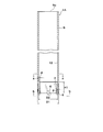
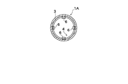
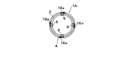
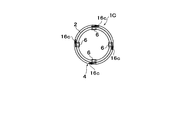
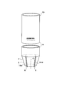
- FIG. 2 is a cross-sectional view taken along the line aa in FIG. 1B. It is a bb arrow line view of FIG. 1B. It is a perspective view which shows the steel pipe pile which has protrusion in the front-end
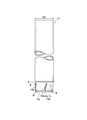
- FIG. 3C is a cross-sectional view taken along the line cc in FIG. 3B.
- FIG. 3D is a dd arrow view of FIG. 3B.
- FIG. 6B is a cross-sectional view taken along the line ee of FIG. 6B.
- FIG. 6F is a view on arrow ff in FIG. 6B.
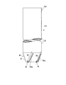
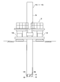
- It is a side view which shows the shape and attachment range of the protrusion provided in the steel pipe pile of 7th Embodiment of this invention.
- It is sectional drawing which shows the shape and attachment range of the protrusion provided in the steel pipe pile of 7th Embodiment of this invention.
- It is a front view which shows the state which is carrying out the rotation press-fit of the steel pipe pile to the ground with the rotation press-fitting construction machine.
- FIG. 22B is a longitudinal front view of FIG. 22A. It is sectional drawing in the gg arrow of FIG. 22B.
- FIG. 1A to 1D show a steel pipe pile (hereinafter, also referred to as a steel pipe pile 1A with a tip tapered protrusion) 1 according to a first embodiment of the present invention.
- the steel pipe pile 1 ⁇ / b> A is open at the front end (front end) 4 a in the excavation direction A ⁇ b> 1 and is hollow, and includes a constant diameter portion 9 and a tapered portion (tip end portion) 4.
- the constant diameter portion 9 has a constant outer diameter.
- the tapered portion 4 is tapered, and the tapered portion 4 is provided with a protrusion 16a.
- the inner peripheral surface 3 of the taper portion 4 has a tapered shape in which the inner dimension gradually decreases in the length direction toward the tip 4a.
- the outer peripheral surface 2 of the taper part 4 is a taper shape from which an external dimension gradually reduces in the length direction toward the front-end
- a plurality of excavation bits 6 are provided at the front end 4a of the taper portion 4 at equal angular intervals in the circumferential direction. When a plurality of even-numbered excavation bits 6 are provided, they are arranged symmetrically with respect to the plane including the central axis C of the steel pipe pile 1A, and when a plurality of odd-numbered excavation bits 6 are provided, they are provided at equiangular intervals.
- the excavation bit 6 is fixed to the tip 4a of the steel pipe pile 1A through a holder part (not shown) as appropriate.
- the excavation bit 6 at the tip of the steel pipe pile 1A with the tip tapered protrusion it is possible to penetrate the steel pipe pile 1A while excavating the ground in the rotary press-fitting method even if the ground is hard. it can.
- the steel pipe pile 1 ⁇ / b> A can be penetrated into the support layer 8 made of the hard ground 15 while rotating and excavating in the arrow X direction and the arrow Y direction.
- a rotary press-fitting construction machine 7 as shown in FIG. 9 or a pile construction machine equipped with a leader for pile driving is used.
- a form in which the excavation bit 6 is provided at the front end 4a of the tapered portion 4 is preferable, but a form in which the excavation bit 6 is not provided may be employed.
- the excavation bit 6 is provided at the tip 4 a of the taper portion 4, and the excavation bit 6 at the tip 4 a of the steel pipe pile 1 A has a radius of the taper portion 4 rather than the outer dimension D 1 of the constant diameter portion 9. Arranged inside the direction.
- the plane of the steel pipe pile 1A with the excavation bit is compared with the case where the excavation bit 6 is provided in the tapered portion 4 of the straight steel pipe pile (steel pipe pile having only a constant diameter portion) 10 as shown in FIGS. 22A to 22C.
- the outer diameter can be reduced.
- a protrusion 16 a is provided on the outer peripheral surface 2 of the tapered portion 4. As shown in FIGS. 1A and 1B, the protrusion 16 a extends partly or entirely from the front end 4 a toward the rear end 9 a and protrudes outward in the radial direction of the tapered portion 4.
- the protrusion 16 a of this embodiment is provided on a part of the outer peripheral surface 2 of the tapered portion 4.
- a plurality of protrusions 16 a are provided at intervals in the circumferential direction of the outer peripheral surface 2 of the tapered portion 4.
- the protrusion 16a is inclined such that the upper portion in the direction of the central axis C of the steel pipe pile 1A is rearward in the pile rotation direction when rotating and penetrating.
- the protrusion 16a is inclined so that the rear end 9a side of the protrusion 16a is behind the constant diameter portion 9 and the tapered portion 4 in the rotation direction.
- the upper portion of the protrusion 16a in the central axis C direction is inclined so as to be rearward in the rotational direction of the steel pipe pile 1A with respect to the lower side, so that the excavation bit is indicated by an arrow B1 in FIG. 1A. It is possible to guide excavated soil (shear) flowing upward on the outer peripheral surface 2 side excavated by 6 or earth and sand sheared and destroyed by the projection 16a in a direction in which the projection is inclined.
- the protrusion 16 a is arranged to be inclined in the circumferential direction with respect to the central axis C of the tapered portion 4.
- the central axis C2 of the protrusion 16a is inclined with respect to the front surface 4a of the tapered portion 4 at an angle ⁇ . That is, the angle formed by the central axis C2 of the protrusion 16a and the front surface 4a may be 90 °, but in the present embodiment, the angle ⁇ is less than 90 °. Details of the angle ⁇ will be described later.
- the tapered portion 4 By providing the tapered portion 4 at the tip 4a of the steel pipe pile 1A, an effect of greatly reducing the ground resistance due to the blockage in the steel pipe pile 1A can be expected. However, since the tapered portion 4 receives a large resistance, Wear and deformation occur. Therefore, in the present embodiment, a plurality of protrusions 16a are provided on the outer peripheral portion 2 of the tapered portion 4, which is the portion that receives the most resistance when the steel pipe pile 1A is penetrated.
- a form for providing the protrusion 16a a form in which the protrusion 16a is fixed to the outer peripheral surface 2 of the taper portion 4 by welding a rod-shaped steel material such as a reinforcing bar or flat steel is also possible. 2 may be subjected to overlay welding to form protrusions, and when the tapered portion 4 is formed, a protrusion by rolling may be provided.
- a protrusion by rolling for example, a fan-shaped steel sheet with a single-sided protrusion is arranged so that the protruding part is outside the pile and is inclined in the central axis direction of the pile, and is bent into a truncated cone shape. The end is closed by welding to form a truncated cone.
- a steel pipe pile 1A having a tapered portion 4 is obtained.
- the steel pipe pile 1A having the tapered portion 4 of the present embodiment can be obtained.
- the protrusion 16a is linear from the front end 4a to the rear end 9a of the steel pipe pile 1A, and the protrusion 16a is also linear in the circumferential direction. May be.
- the width dimension in the central axis C direction of the steel pipe pile 1A is constant as the width dimension of the protrusion 16a in the pile circumferential direction, but the upper side (rear end 9a side) of the protrusion 16a is narrowed. It may be provided as follows.
- the width dimension of the protrusion 16a in the circumferential direction of the steel pipe pile 1A is such that when the soil is guided along the protrusion 16a to the upper portion of the outer peripheral surface 2 of the tapered portion 4, the upper end from the upper end of the protrusion 16a. At the moment of separation, the width dimension portion in the pile circumferential direction of the protrusion 16a becomes a space. Thereby, earth and sand etc. can be poured smoothly.
- a lower end portion of the protrusion 16a may be provided so as to be connected to an upper attachment portion of the excavation bit 6.
- the soil can be efficiently guided and flowed along the outer peripheral surface 2 of the taper part 4 by the excavation bit 6 and the protrusion 16a connected to this.
- the protrusion 16b may be provided in a state of being spaced apart from the excavation bit 6 in the circumferential direction of the steel pipe pile 1B.
- the protrusion extends from the excavation bit 6 to the rear side of the rotation direction of the steel pipe pile 1 (forward rotation direction) in the range of about the width dimension of the excavation bit 6 in the circumferential direction of the pile. It is provided at a position separated in the rear or pile axis direction. Even in this case, similarly to the first embodiment, as indicated by an arrow B1 in FIG.
- the earth and sand to be sheared can be guided in the direction in which the protrusions are inclined.
- the excavated soil and earth and sand can be smoothly flowed backward in the excavation direction A1.
- the protrusions 16a and 16b have been described as being configured to be continuous in at least one of the central axis C direction and the circumferential direction of the steel pipe pile 1C, but as shown in FIGS. 3A to 3D.
- the protrusions 16c may be intermittently disposed. That is, as shown in FIGS. 3A and 3B, the two protrusions 16c may be arranged at an interval in the excavation direction A1. As described above, when a plurality of protrusions 16c are provided intermittently in the excavation direction A1, three or more protrusions 16c may be intermittently arranged in series at intervals.
- the protrusions 16a to 16c are inclined with respect to the central axis C.
- the protrusions 16a to 16c may not be inclined.
- the protrusion 16d extends along the central axis C of the steel pipe pile 1D.
- the lower end 16e of the protrusion 16d is positioned immediately above the upper surface 6a of the excavation bit 6, as shown in FIG. 4B.
- the soil is guided by the protrusion 16d so as to flow along the outer peripheral surface 2 of the tapered tip end portion 4 in the direction of the central axis C of the steel pipe pile 1D.
- the projection 16d having such a shape may be used, in the case of considering that the steel pipe pile 1D is to be rotated, the steel pipe piles 1A to 1C in the positive rotation direction are provided like the projections 16a to 16c described in the above embodiments.
- the protrusions 16a to 16c are inclined rearward, the soil flow along the outer peripheral surface 2 of the tapered portion 4 becomes smooth.
- the excavation bit 6 and the projection 16d are connected, the soil excavated by the excavation bit 6 and the soil (shear) sheared by the projection 16d are efficiently flowed upward along the tapered portion 4. Can do.
- the taper part 4 of the steel pipe pile 1E is provided with a pointed part 5 protruding from the tip 4a and sharpened in the excavation direction A1.
- a concave portion 5 a is provided at the tip 4 a of the tapered portion 4.
- the recess 5a is not necessarily formed.
- the protrusion 16e extends from the front end 4a toward the rear end 9a over the entire outer peripheral surface 2 of the tapered portion 4.
- the tip 4a of the tapered portion 4 between the excavation bits 6 shown in FIG. 1A may be provided with a sharp portion 5b sharpened in the excavation direction A1.
- the tip of the sharp portion 5b is flat.
- the tip may be sharpened similarly to the fifth embodiment, and the tip of the sharpened portion 5 of the fifth embodiment may be flattened.
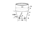
- FIG. 7A and FIG. 7B are explanatory views showing the shape and attachment range of protrusions provided on the steel pipe pile 1G.
- the length of the protrusion 16g in the direction from the front end 4a to the rear end 9a may be provided over substantially the entire outer peripheral surface 2 of the tapered portion 4.
- the height of the protrusion 16g may be set in order to suppress the reduction in the peripheral friction of the steel pipe pile 1G as much as possible. For example, as shown in FIG.
- the height H2 of the protrusion 16g is defined so that the protrusion 16g is located on the inner side in the radial direction of the tapered portion 4 with respect to the outer dimension of the constant diameter portion 9.
- the height of the protrusion 16g and the extension of the protrusion 16g are such that the protrusion 16g is located on the inner side in the radial direction of the steel pipe pile 1G with respect to the outer shape extension line 18 of the constant diameter portion 9 extending toward the tapered portion 4 side.
- the position of the upper end portion of the center axis C2 in the current direction is restricted.
- the protrusion 16g is provided, the range which disturbs soil with the protrusion 16g decreases, and the reduction of the peripheral surface friction of the steel pipe pile 1G can be suppressed.
- the length of the protrusion 16g in the extending direction may be shorter than that in the above-described embodiment in a range that is inside the outer shape extension line 18 of the constant diameter portion 9.
- the inclination angle of the protrusion 16g will be described with reference to FIGS. 7A and 7B.
- the inclination angle ⁇ ) at which the central axis C2 of 16 g intersects is in the range of 20 ° to 90 °, preferably 20 ° to 70 °, and more preferably 30 ° to 50 in accordance with the internal friction angle ⁇ of the normal ground.
- the soil can be efficiently sheared and broken by the shortest protrusion 16g when the steel pipe pile rotates.
- the guide action of the soil accompanying the forward rotation of the steel pipe pile is small, the action of efficiently flowing the excavated soil (shear) from the tapered portion 4 to the upper side is reduced.
- the inclination angle ⁇ of the protrusion 16g is less than 20 °, the length range in which the protrusion 16g is provided in the circumferential direction of the steel pipe pile becomes longer, which is not economical, and the shear fracture efficiency of the soil decreases.
- the lower limit of the inclination angle ⁇ of the protrusion 16g is set to 20 °. Further, when the inclination angle ⁇ of the protrusion 16g is about 20 ° to 70 °, the burden per unit length of the protrusion when shearing the soil is significantly reduced as compared with the case of 90 °. Furthermore, the guide action of the excavated soil can be reliably exhibited. Moreover, when the inclination angle ⁇ of the protrusion 16g exceeds 90 °, the shear broken by the protrusion 16g is pushed downward with respect to the construction in the forward rotation direction of the steel pipe pile. In addition, the shear fracture efficiency due to the protrusions 16g is also reduced. Thus, as described above, the best range is set to a range of 30 ° to 50 ° in consideration of the internal friction angle ⁇ of the soil. The range of the inclination angle ⁇ is the same in the above embodiments.
- the height dimension of the protrusion 16g will be described with reference to FIG. 7B.
- the outer diameter of the steel pipe pile is about 400 mm to 2500 mm. Therefore, the height dimension H2 of the protrusion 16g in the pile radial direction is about 12 mm at the maximum in the steel pipe pile with the outer diameter of 400 mm, and the steel pipe pile with the outer diameter of 2500 mm. Then, it is about 15 mm to 75 mm.
- the height dimension H2 of this protrusion is the same in the above embodiments.
- the protrusion interval between the protrusions 16g adjacent in the circumferential direction of the steel pipe pile is not particularly specified.
- the protrusion interval between the protrusions 6g adjacent in the peripheral direction of the steel pipe pile is provided at the same angular interval.
- it may be provided in the same phase as the excavation bit 6 or may be provided in the vicinity of the excavation bit 6 at the same equiangular interval or at different arrangement intervals.
- the position of the lower end portion of the protrusion 16g may be provided so as to be connected to the upper end portion of the excavation bit 6.
- the form of the taper part of the steel pipe pile used for the test is a steel pipe pile 1G having a protrusion 16g on the taper part 4 of the seventh embodiment shown in FIGS. 7A and 7B, and a taper part shown in FIGS. 8A and 8B as a comparative example.
- a test was conducted on a steel pipe pile 17 having a shape in which no protrusions were provided in FIG.
- the steel pipe piles 1G and 17 of both test bodies used for the test are provided with four excavation bits 6 at equal angular intervals in the taper portion 4.
- the outer diameter dimension D1 of the constant diameter portion 9 having a constant outer diameter in each of the steel pipe piles 1G and 17 is 1000 mm.
- the steel pipe pile 1G of this embodiment which provided the 1986
- the protrusion 16g was fixed to the taper portion 4 by welding from the position immediately above the excavation bit 6 to the upper end of the taper portion 4 so as to be connected to the excavation bit 6 to be a steel pipe pile 1G.
- the ground is soft rock (mudstone) having a uniaxial compressive strength of 5 N / mm 2 , and is rotationally press-fitted from this ground to a depth that is three times the outer diameter D1 of each steel pipe pile 1G, 17.
- the construction load per unit area of the pile head pressure input: kN / m 2
- the amount (penetration ratio) was measured, and the relationship between these construction loads and the penetration amount (penetration ratio) was shown in a graph in FIG. As shown in FIG.
- the pressure input is a maximum of 645 kN / m 2 , whereas the embodiment having the protrusion 16g in the tapered portion 4 is shown.
- the maximum pressure input was 363 kN / m 2 . That is, it can be seen that a construction load of about 30% or more can be reduced.
- a construction load can be reduced, since a construction load can be reduced, a counterweight can be decreased.
- the construction load can be reduced by about 30% or more, the capacity of the construction machine can be reduced. With existing construction machines, for example, construction can be performed using a small construction machine one rank below. Cost can be significantly reduced.
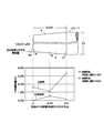
- the graph of the result of having measured about the average abrasion amount (%) of the center axis C direction of the steel pipe pile 1G and 17 in the outer peripheral surface of the taper part 4 is shown in FIG. .
- the measurement position of the wear amount is shown in the lower diagram of FIG. 11 as a result of measurement at three locations A, B, and C indicated by arrows in the upper diagram of FIG. From FIG.
- tip At the upper end of the portion 4 (the position of 0.5D1 in the graph) and the center thereof (the position of 0.25D1), the average wear amount is significantly reduced to half or less.
- the average wear amount (%) is a value (ratio) when the original plate thickness of the tapered portion 4 is 1.
- the average wear amount (%) is a value obtained by averaging the wear amounts of a plurality of specimens.
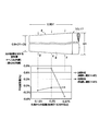
- F is a graph showing the result of measurement at the position indicated by F.
- the measurement point of the tapered portion 4 having the protrusion 16g of the present invention was measured along the protrusion 16g.
- deformation to is displayed as-(minus) deformation.
- the taper portion 4 is deformed by being dented toward the central axis C on the distal end side in the axial direction, and the proximal end side in the axial direction (large diameter On the side), it begins to swell.
- the tapered portion 4 has a minute bulge in the pile axial direction, whereas the deformation form of the tapered portion 4 is reversed in the axial direction (swells after being dented). It turns out that it is only. From the graphs of FIG. 11 and FIG.
- the taper portion 4 has a taper portion 4 that is not provided with the protrusions 16g. It can be seen that the amount of wear and the amount of deformation are greatly improved.
- the protrusion 16g is provided on the taper portion 4, the plate thickness of the portion provided with the protrusion 16g is naturally increased, the rigidity is increased, and the rigidity of the entire taper portion 4 is improved.
- the following effects (1) to (4) can be expected.
- the ground (soil) in the vicinity of the outer peripheral surface 2 of the tapered portion 4 can be efficiently and actively destroyed (sheared) by the protrusions 16g to facilitate the rotary insertion of the pile. it can.
- the wear and deformation of the taper portion 4 which is an important member for exerting the pile bearing capacity performance by the protrusion 16g portion taking on the wear and deformation caused by the resistance of the ground at the taper portion 4 originally. It can suppress, and the soundness (safety) of a pile body can be improved significantly.
- the protrusion 16g By providing the projection 16g by connecting to the top surface of the excavation bit 6, the earth and sand excavated by the excavation bit 6 flows upward along the projection 16g, so that the resistance of the pile construction is reduced.
- the protrusion 16g is provided with an attachment angle ⁇ so as to intersect the axis in the direction of the central axis C of the steel pipe pile 1G, so that when the pile is rotated, the protrusion 16g is sheared by the protrusion 16g. An effect of causing the broken soil to flow upward by the protrusions 16g can be exhibited. Furthermore, the ground resistance when constructing the pile can be reduced. In this test, the steel pipe pile 1G of the seventh embodiment has been described, but the same effect can be obtained even if the steel pipe piles 1A to 1F of other embodiments are used.
- the hard ground means a rock
- the rock is divided into a soft rock base (uniaxial compressive strength to less than 20 MPa) and a hard rock base (uniaxial compressive strength: 20 MPa or more).
- the steel pipe piles 1A to 1G with tapered protrusions can be applied to any rock in the form of having the excavation bit 6.
- the outer side and the inner side are as shown in FIG. It may be linear, and although not shown, it may be curved.
- the protrusions 16a to 16e and 16g are provided, they are directly installed on the outer peripheral surface 2 of the tapered portion 4.
- FIGS. 13A and 13B are views in which the protrusions a to 16e and 16g are omitted.
- FIGS. 13A and 13B are views in which the protrusions a to 16e and 16g are omitted.
- the taper part 4 By providing the taper part 4 at the tip of the pile, the resistance of the soil acting on the inner peripheral surface 3 of the taper part 4 increases, but by adopting a method of rotary press-fitting construction, the friction on the pile peripheral surface is increased. It also takes advantage of the fact that it can be suppressed. Further, by providing the projections 16a to 16e, 16g, the soil acting on the inner peripheral surface 3 of the tapered portion 4 can be promoted to move upward from the inner peripheral surface 3, thereby reducing the resistance of the soil.
- the diameter reduction ratio which is the ratio between the outer diameter D2 of the tip 4a of the tapered portion 4 and the outer diameter D1 of the constant diameter portion where the outer diameter of the steel pipe pile is constant, is small, and the pile longitudinal direction (axial direction) of the tapered portion 4 If the ratio (H1 / D1) between the length H1 of the taper and the outer diameter dimension D1 of the constant diameter portion having a constant outer diameter becomes too small (in other words, the taper angle ⁇ (°) of the tapered portion 4 becomes too large). And), the resistance due to the surface pressure acting on the tapered portion 4 is increased during the rotary press-fitting. As a result, construction failure may occur.
- the length H1 of the tapered portion 4 in the pile length direction (same as the direction of the central axis C of the steel pipe pile), the outer diameter D2 at the tip of the tapered portion 4, and the constant diameter is constant.
- tan ⁇ (D1 ⁇ D2) / 2H1 between the outer diameter D1 of the portion and the taper angle ⁇ .
- the taper portion 4 has a pile penetration direction and a taper angle ⁇ in addition to the movement in which the rotation direction and the penetration direction vertical are combined with the ground. As a result, the effect of spreading the ground sideways while simultaneously applying the shearing force and the compressive force to the ground is exhibited. Therefore, the ground can be disturbed efficiently, and the resistance during construction of the tapered portion 4 is reduced.
- Providing the tapered portion 4 increases the projected area of the bottom surface of the pile, so that when the taper portion 4 penetrates into the support layer, a reliable support force can be obtained by the tapered portion 4.
- a reliable supporting force can be exhibited even if the blockage in the pipe is insufficient. Since a high compressive load can be borne in the area of the projected area of the bottom surface of the tapered portion 4, the steel pipe piles 1A to 1G should have a higher bearing capacity than when a normal straight open-ended pile is inserted by rotary press-fitting. Can do.
- the steel pipe piles 1A to 1G surely exhibit a high supporting force. Therefore, a higher supporting force can be expected than when a straight steel pipe pile with a closed end 4a is inserted by rotary press-fitting.
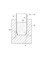
- the steel pipe piles 1A to 1G are installed by rotary press-fitting, the steel pipe piles 1A to 1G are repeatedly moved up and down alternately in the ground during the construction, so that the soil in the pipe is moved below the pipe during the upward movement. It falls and the soil that falls when moving down is pushed out of the pipe. As a result, as shown in FIGS.
- the height of the soil in the pipe can be lowered, and the contact surface between the inner peripheral surface 12 of the constant diameter portion 9 and the pipe inner soil 14 can be reduced.
- the friction between the inner peripheral surface 12 and the pipe soil 14 is reduced, the construction load can be further reduced.
- the ratio (H1 / D1) between the length H1 of the tapered portion 4 in the pile longitudinal direction and the outer diameter D1 of the constant diameter portion 9 having a constant outer diameter is set to 0.3 to 5.5.
- H1 / D1 is set to 0.3 to 5.5.
- the diameter reduction ratio (D2 / D1) which is the ratio (D2 / D1) between the outer diameter dimension D2 of the tip of the tapered portion and the outer diameter dimension D1 of the constant diameter portion 9 having a constant outer diameter of the steel pipe pile, is 0.
- the outer diameter dimension D2 is set smaller than the outer diameter dimension D1 so as to be in the range of .60 to 0.95.
- the ratio (H1 / D1) with the outer diameter D1 of the portion 9 and the necessary pushing force ratio (the ratio between the necessary pushing force of the steel pipe pile 1A having the tapered portion 4 and the necessary pushing force of the straight steel pipe pile 10) It is the graph which investigated this relationship by experiment.
- the steel pipe pile 1A used in the experiment has an outer diameter dimension (D1) of the constant diameter portion 9 of 100 mm, a thickness (t) of the steel pipe portion of 4.2 mm, and an outer diameter dimension of the tip 4a of the tapered portion 4 ( D2) is 90 mm. Further, the outer diameter dimension (D1) of the straight steel pipe pile 10 having a constant outer diameter dimension (D1) over the entire length and the thickness (t) of the steel pipe portion are the same as those of the steel pipe pile 1A.
- the necessary pushing force ratio is 0.9 or less, and the steel pipe pile 1A is at least 10% of the straight steel pipe pile 10 shown in FIG. 22A. It can be seen that the necessary pushing force can be reduced. In addition, when H1 / D1 is 0.40 to 1.35, the required pushing force ratio is 0.6 or less, and in steel pipe pile 1A, the necessary pushing force is reduced by 40% compared to straight steel pipe pile 10. You can see that you can.
- FIG. 20 shows a curve obtained by plotting experimental values.
- This figure shows a reduction ratio (D2) which is a ratio of the outer diameter D2 of the tip 4a and the outer diameter D1 of the constant diameter portion 9. / D1) is a graph in which the required indentation force ratio is examined and compared for steel pipe piles 1A with various diameter reduction ratios on the horizontal axis.
- the necessary pushing force ratio is 0.90, and when the diameter reduction ratio (D2 / D1) is 0.75, the necessary pushing force is obtained.
- the necessary pushing force ratio is 0.60, and when the diameter reduction ratio (D2 / D1) is 0.95, It can be seen that the necessary pushing force ratio is 0.90. From these downwardly convex graphs shown in FIG. 19 and FIG. 20, the necessary pushing force ratio is reduced to 0.90 or less when the diameter reduction ratio (D2 / D1) is in the range of 0.60 to 0.95.
- the pushing force can be reduced by at least 10%.
- the diameter reduction ratio (D2 / D1) when the diameter reduction ratio (D2 / D1) is in the range of 0.75 to 0.92, the required pushing force ratio becomes 0.60 or less, and the necessary pushing force can be reduced by 40%. Accordingly, it is preferable that H1 / D1 is set to 0.3 to 5.5, and the diameter reduction ratio (D2 / D1) is set to 0.60 to 0.95, and more preferably, H1 / D1 is set to 0.3 to 5. And the diameter reduction ratio (D2 / D1) is preferably in the range of 0.75 to 0.92.
- the counterweight can be greatly reduced.
- the required push-in force can be reduced by 10% to 8.6 t (tons).
- the counter weight can be reduced by 13%.
- H1 / D1 is 0.40 to 1.35
- the necessary pushing force ratio can be reduced to 0.6 or less, and the counterweight can be further reduced.
- FIGS. 21A and 21B A resistance reduction mechanism when the steel pipe pile 1A is rotationally press-fitted into the ground will be described with reference to FIGS. 21A and 21B.
- FIG. 21B the figure which abbreviate
- a and a ′ are resistances at the tip closing part
- b is resistance at the tip outer peripheral surface
- b ′ is resistance by the taper part 4
- c and c ′ Is a resistance due to friction of the outer peripheral surface 2 of the tapered portion 4, and ⁇ is a resistance due to the soil in the pipe.
- the tapered portion 4 of the steel pipe pile 1A of the present invention has the above-described action, and further, the tapered portion 4 is provided with the protrusion 16a, so that the resistance due to the contact between the tapered portion 4 and the ground contacts the tapered portion 4.
- the soil can be actively sheared and reduced.
- the crushing can be efficiently performed by adjusting the inclination angle ⁇ of the protrusion 16a to 30 ° to 50 ° to the internal friction angle ⁇ of the normal ground.
- the sharp portion 5 sharpened toward the excavation direction A1 may be the sharp portion 5 sharpened toward the excavation direction A1.
- a portion sharpened in the circumferential direction of the pile may be provided.
- the tip 4a of the tapered portion 4 is provided with a sharp portion 5 sharpened in the excavation direction A1, even if the ground is hard, the excavation bit 6 and the sharp portion 5 or
- the sharpened portion 5 also serving as the excavating bit 6 of the tapered portion 4 allows the steel pipe pile to penetrate into the ground while destroying or excavating the tip portion ground at the time of pile driving construction.
- the rotary press-in method for applying rotational force and indentation force to the steel pipe pile is applied to the ground as in the prior art. Just press fit.
- the rotary press-fitting construction machine 7 as shown in FIG. 9 grips the peripheral side surface of the steel pipe pile 17 or the like with the tip tapered portion, and the rotary press-fitting construction is performed, the outer diameter dimension of the conventional steel pipe pile 10, that is, the steel pipe pile.
- the steel pipe piles 1A to 1G of the present invention Compared with the case of constructing a straight steel pipe pile 10 having the same thickness D1 and its thickness t, the steel pipe piles 1A to 1G of the present invention have a penetration amount per pushing force shown in FIG. 17 and a tip load degree shown in FIG. It can be seen that it is excellent in terms of (kN / m 2 ).
- FIG. 17 shows a pressing force per closed cross-sectional area of the pile, which is a construction load at the time of construction using a pile having an outer diameter D1 and an outer diameter D2 at the tip of the tapered portion 4 as shown in FIG.
- the relationship of (kN / m 2 ) ⁇ penetration / pile diameter (H2 / D1) is shown. It can be seen that the penetration amount of the steel pipe piles 1A to 1G of the present invention is larger than that of a straight steel pipe pile (shown as a straight pile in FIG. 17) as shown in FIG. 22A. Further, FIG.
- FIG. 18 shows a tip load degree (kN / m 2 ) when a static load is applied after rotating and press-fitting a steel pipe in a hard ground for a length three times the outer diameter D1. -The tip settlement / pile diameter (D1) relationship is shown.
- the steel pipe piles 1A to 1G according to the present invention have a larger load on the tip and a higher supporting force than the straight pile.
- the steel pipe piles 1A to 1G When constructing the steel pipe piles 1A to 1G of the present invention or the steel pipe pile 17 not provided with the protrusions, the steel pipe piles 1A to 1G may be inserted into the support layer under the soft ground or may be rotationally press-fitted into the ground including the hard ground.
- a hydraulic type telescopic jack or the like in the rotary press fitting machine 7 while holding the steel pipe piles 1A to 1G with a taper at the tip by the rotary press fitting machine 7 is used. 13 is expanded and contracted. Thereby, the steel pipe piles 1A to 1G can be easily moved up and down.
- the steel pipe piles 1A to 1G when the tapered portion 4 of the steel pipe piles 1A to 1G is finally stopped in the support layer, the steel pipe piles 1A to 1G are reversely rotated, and the protrusions 16a to 16e, The soil (shear including crushed stone) near the tapered outer peripheral surface is pushed downward by 16 g. As a result, the protrusions 16a to 16e, 16g can push the soil (slipping including crushed stones) near the tapered outer peripheral surface downward, thereby densely supporting the pile lower surface side and supporting the pile.
- a taper portion of one steel pipe pile may be produced by cold bending.
- the belt-shaped steel plate is formed into a fan shape, and the fan-shaped steel plate with protrusions is processed into a taper shape by cold bending, and both side edges are joined by welding.
- a tapered short pipe having the same outer diameter as the steel pipe to which the outer diameter portion is to be connected is manufactured, and the upper end portion of the tapered short pipe is fixed to the tapered portion of one steel pipe by welding.
- a steel pipe pile body may be manufactured.
- a steel pipe pile with a tip tapered portion protrusion may be manufactured by fixing a holder having a drilling bit to such various types of tapered portions and providing a protrusion by welding or the like.
- the strip-shaped steel plate with a single-sided projection is made into a fan-shaped steel plate with a projection, and a tapered short tube is manufactured, and the upper end of the tapered short tube is fixed to the tapered portion of one steel pipe by welding. You may make it manufacture the steel pipe pile etc. with a taper part protrusion.
Landscapes
- Engineering & Computer Science (AREA)
- Structural Engineering (AREA)
- Life Sciences & Earth Sciences (AREA)
- General Life Sciences & Earth Sciences (AREA)
- Mining & Mineral Resources (AREA)
- Paleontology (AREA)
- Civil Engineering (AREA)
- General Engineering & Computer Science (AREA)
- Piles And Underground Anchors (AREA)
- Placing Or Removing Of Piles Or Sheet Piles, Or Accessories Thereof (AREA)
Abstract
この鋼管杭は、掘削方向の前端が開口し、かつ、中空である鋼管杭であって、外径寸法が一定である定径部と、前記前端に向かって内形寸法及び外形寸法が漸次小さくなる先端部とを備え;前記先端部の外周面に、前記前端から後端に向かって一部または全体に延在し、かつ、前記先端部の半径方向外方に突出する突起が設けられている。
Description
本発明は、港湾構造物あるいは橋梁の基礎や建物の基礎等、土木・建築分野においてに使用される鋼管杭及びその施工方法に関する。
本願は、2010年07月05日に、日本に出願された特願2010-153290号に基づき優先権を主張し、その内容をここに援用する。
本願は、2010年07月05日に、日本に出願された特願2010-153290号に基づき優先権を主張し、その内容をここに援用する。
従来、摩擦杭として、杭の周面摩擦力を高めるために、杭の先端部の外周面をテーパー状外周面とすること、または杭全長の外周面をテーパー状外周面とし、杭の先端部のテーパー部から外径が一定の定径部の全長にわたり、鉄筋を螺旋状に巻き付けることが知られている(例えば、特許文献1参照)。このような摩擦杭には、杭の外周面の摩擦力が期待されている。
また、杭の長さ方向の中間部の外周面に、杭軸方向に間隔をおいて螺旋翼を複数設ける共に、杭の先端部のコーン部分に螺旋翼における翼ピッチ(推進ピッチ)と同じ間隔で、前記コーン部分に同じ推進ピッチで螺旋状に帯鋼を溶接等により固定することも知られている(例えば、特許文献2参照)。
また、杭の長さ方向の中間部の外周面に、杭軸方向に間隔をおいて螺旋翼を複数設ける共に、杭の先端部のコーン部分に螺旋翼における翼ピッチ(推進ピッチ)と同じ間隔で、前記コーン部分に同じ推進ピッチで螺旋状に帯鋼を溶接等により固定することも知られている(例えば、特許文献2参照)。
杭を地盤に貫入させる場合には、テーパー状の外周面部分の平面投影面積が大きいと、杭貫入完了後においては、杭の支持力を発揮する部分になる。その反面、杭施工時においては、特に一軸圧縮強度が3N/mm2を超えるような軟岩や中硬岩、硬岩といった岩盤の中間層を打ち抜く必要がある場合や、支持層が岩盤であり、そこに杭を貫入させる場合には、テーパー状の外周面部分が大きな貫入抵抗となる。
場所打ち鉄筋コンクリート杭や既成コンクリート杭を埋設するために、先端側をテーパー状の外周面およびテーパー状の内周面としたケーシングを用いることも知られている(例えば、特許文献3参照)。
杭を回転圧入施工によって地中に貫入させる際、貫入深度が大きくなるに従い、管内閉塞土の抵抗が大きく発生するため、高い押込み力・回転力が必要となる。ここで、押込み力とは、杭を地中の貫入方向に押し下げるために加える力を指す。また、回転力は、杭を回すために加える力を指す。
杭を回転圧入する押込み力を確保するためには、反力が必要となり、反力を確保するためには、回転圧入施工機にカウンタウェイトを設置したり、アンカー等を設けたりすることが必要となる。これらの輸送費や作業費、材料費などが必要となり、杭の施工コストが増加することになる。また、押込み力を確保するためには、回転圧入施工機も大能力化・大型化することになるので、杭施工コストを一段と増加させることになる。
さらに、杭の推進力を獲得するために、杭に推進用の螺旋翼あるいは羽根などの治具を取付けると、加工費および取付け費用や材料費が掛かり、さらには、軟弱地盤の施工においては、逆に、螺旋翼あるいは羽根の間隔で、施工速度が制限されてしまうため、施工速度の低下に繋がる。
また、既成杭を支持層に貫入後、より高い支持力を獲得するために、既成杭の先端を確実に閉塞させる工法がある。この方法では、杭先端の土を完全に排除した後、コンクリートを打設したり、杭先端にセメントミルクを注入して根固め部を造成したりする必要がある。
杭を回転圧入する押込み力を確保するためには、反力が必要となり、反力を確保するためには、回転圧入施工機にカウンタウェイトを設置したり、アンカー等を設けたりすることが必要となる。これらの輸送費や作業費、材料費などが必要となり、杭の施工コストが増加することになる。また、押込み力を確保するためには、回転圧入施工機も大能力化・大型化することになるので、杭施工コストを一段と増加させることになる。
さらに、杭の推進力を獲得するために、杭に推進用の螺旋翼あるいは羽根などの治具を取付けると、加工費および取付け費用や材料費が掛かり、さらには、軟弱地盤の施工においては、逆に、螺旋翼あるいは羽根の間隔で、施工速度が制限されてしまうため、施工速度の低下に繋がる。
また、既成杭を支持層に貫入後、より高い支持力を獲得するために、既成杭の先端を確実に閉塞させる工法がある。この方法では、杭先端の土を完全に排除した後、コンクリートを打設したり、杭先端にセメントミルクを注入して根固め部を造成したりする必要がある。
また、先端が開口し、その杭先端部に掘削ビットを設けたビット付き開端杭では、回転圧入施工時には開端杭の地中への貫入量に伴い、管内に土が流入し、堆積する。これにより、杭の先端部の閉塞度合が高まり、杭圧入時の抵抗の原因となる。前記の杭先端の閉塞は、管内に流入した砂や粘土や石といった地盤を構成する材料(土)と、杭内側の内周面との摩擦によって生じる。
特に、杭回転圧入施工時に問題となるのは、杭を地中の貫入方向に押し込む押込み力である。これは、杭回転圧入施工時においては、反力を、通常、錘や施工用の機械自体の自重で得るため、反力を大きくするためには、錘が多く必要になり不経済である。回転方向の力は、反力を反力獲得用の棒状の治具等で他の重機などに当てるなどして取ることができるため、問題になることは少ない。
特に、杭回転圧入施工時に問題となるのは、杭を地中の貫入方向に押し込む押込み力である。これは、杭回転圧入施工時においては、反力を、通常、錘や施工用の機械自体の自重で得るため、反力を大きくするためには、錘が多く必要になり不経済である。回転方向の力は、反力を反力獲得用の棒状の治具等で他の重機などに当てるなどして取ることができるため、問題になることは少ない。
外径が一定の定径部に螺旋状に突起を設けた杭の場合には、杭を回転圧入して施工したときに、定径部の部分に設けた螺旋状の突起が、杭の外周面部分の周囲地盤を乱す。これにより、鋼管杭の周面と周囲地盤との杭周面摩擦抵抗が低減する可能性がある。そのため、支持杭に属する杭であっても、定径部の外周面側の地盤を極力乱さないようにすることにより、杭先端支持力と、定径部の周面摩擦抵抗との両方を期待することができる。
また、杭軸方向の全長にテーパー状の外周面を有する杭の場合には、杭の製作コストが高くなると共に、杭施工装置も特殊になり、施工が煩雑になる。
また、施工杭におけるテーパー状の外周面の周方向に螺旋状に数周に亘って推進ピッチとなるように螺旋状突起を設けた場合には、杭回転圧入時におけるテーパー状の外周面付近の土の流れは、螺旋状突起にガイドされるように土は流れる。螺旋状突起により積極的に、土をせん断破壊するものではないため、テーパー外周面と土との付着を低減することが困難になる。
この場合には、テーパー状の外周面部分の平面投影面積が大きくなるほど、押し込み力が大きくなり、また、テーパー状の外周面部分に土が付着することによる抵抗も大きくなる。
また、施工杭におけるテーパー状の外周面の周方向に螺旋状に数周に亘って推進ピッチとなるように螺旋状突起を設けた場合には、杭回転圧入時におけるテーパー状の外周面付近の土の流れは、螺旋状突起にガイドされるように土は流れる。螺旋状突起により積極的に、土をせん断破壊するものではないため、テーパー外周面と土との付着を低減することが困難になる。
この場合には、テーパー状の外周面部分の平面投影面積が大きくなるほど、押し込み力が大きくなり、また、テーパー状の外周面部分に土が付着することによる抵抗も大きくなる。
前記のような杭全長に亘ってテーパー状の外周面を設けたテーパー杭の欠点を解消する技術として、杭の先端部のみにテーパー状の外周面及びテーパー状の内周面を設けた鋼管杭とする発明が本出願人によって出願されている。
このように、鋼管杭の先端にテーパー状の外周面及びテーパー状の内周面を備えたテーパー状部分を設けることで、管内土と杭内周面との摩擦による抵抗を軽減する。これにより、管内に侵入した土砂と鋼管の内側との摩擦により発生する抵抗、いわゆる管内閉塞抵抗を低減することができる。また、テーパー状部分により、杭底面の投影面積が増加し、地盤に対して抵抗するため、容易に高い支持力を得ることができる。特に地盤の拘束圧の高い深い支持層や硬い岩盤層では,テーパー状部分の底面投影面積の部分で高い圧縮荷重を負担できる。また、先端が開口している通常のストレートな鋼管杭よりも高い支持力を発揮することができる。
ただし、先端テーパー状部分を有する鋼管杭では、その先端テーパー状部分は、杭施工時には、前記の先端テーパー状部分が地盤と直接角度をもって接触するため、テーパー状部分に高い荷重が発生する。高い荷重が発生したまま先端テーパー状部突起付きの鋼管杭を回転することで、先端テーパー状部分の鋼材の板厚が摩耗により減少したり、変形を生じたりする恐れがある。また、先端テーパー状部分の荷重は、大きな抵抗が生じるため、施工機械の能力をさらに小さくして施工可能とするためには、さらに抵抗の低減が望まれる。
回転圧入施工により杭を施工する場合には、杭を地中の貫入方向に押し込む押込み力を小さくすることができると、杭一本当たりの施工コストの低減を図ることができる。したがって、多数本の杭が地盤に回転圧入されるため、トータルの施工コストを格段に低減する上で、杭一本当たりの施工コストを低減させることが重要になる。
本発明は、杭の押し込み力を低減することが可能な鋼管杭およびその施工方法の提供を目的とする。
このように、鋼管杭の先端にテーパー状の外周面及びテーパー状の内周面を備えたテーパー状部分を設けることで、管内土と杭内周面との摩擦による抵抗を軽減する。これにより、管内に侵入した土砂と鋼管の内側との摩擦により発生する抵抗、いわゆる管内閉塞抵抗を低減することができる。また、テーパー状部分により、杭底面の投影面積が増加し、地盤に対して抵抗するため、容易に高い支持力を得ることができる。特に地盤の拘束圧の高い深い支持層や硬い岩盤層では,テーパー状部分の底面投影面積の部分で高い圧縮荷重を負担できる。また、先端が開口している通常のストレートな鋼管杭よりも高い支持力を発揮することができる。
ただし、先端テーパー状部分を有する鋼管杭では、その先端テーパー状部分は、杭施工時には、前記の先端テーパー状部分が地盤と直接角度をもって接触するため、テーパー状部分に高い荷重が発生する。高い荷重が発生したまま先端テーパー状部突起付きの鋼管杭を回転することで、先端テーパー状部分の鋼材の板厚が摩耗により減少したり、変形を生じたりする恐れがある。また、先端テーパー状部分の荷重は、大きな抵抗が生じるため、施工機械の能力をさらに小さくして施工可能とするためには、さらに抵抗の低減が望まれる。
回転圧入施工により杭を施工する場合には、杭を地中の貫入方向に押し込む押込み力を小さくすることができると、杭一本当たりの施工コストの低減を図ることができる。したがって、多数本の杭が地盤に回転圧入されるため、トータルの施工コストを格段に低減する上で、杭一本当たりの施工コストを低減させることが重要になる。
本発明は、杭の押し込み力を低減することが可能な鋼管杭およびその施工方法の提供を目的とする。
本発明は、上記課題を解決して係る目的を達成するために以下の手段を採用した。
すなわち、
(1)本発明の一態様に係る鋼管杭は、掘削方向の前端が開口し、かつ、中空である鋼管杭であって、外径寸法が一定である定径部と、前記前端に向かって内形寸法及び外形寸法が漸次小さくなる先端部とを備え;前記先端部の外周面に、前記前端から後端に向かって一部または全体に延在し、かつ、前記先端部の半径方向外方に突出する突起が設けられている。
すなわち、
(1)本発明の一態様に係る鋼管杭は、掘削方向の前端が開口し、かつ、中空である鋼管杭であって、外径寸法が一定である定径部と、前記前端に向かって内形寸法及び外形寸法が漸次小さくなる先端部とを備え;前記先端部の外周面に、前記前端から後端に向かって一部または全体に延在し、かつ、前記先端部の半径方向外方に突出する突起が設けられている。
(2)上記(1)に記載の鋼管杭は、前記突起が、前記先端部の前記外周面の周方向に間隔をあけて複数設けられていることが好ましい。
(3)上記(1)または(2)に記載の鋼管杭では、前記突起の前記後端側が前記定径部及び前記先端部の回転方向の後方になるように、前記突起が傾斜していることが好ましい。
(4)上記(1)または(2)に記載の鋼管杭では、前記突起が前記先端部の中心軸線に対して周方向に傾斜して配置され、前記中心軸線に直角な面と前記突起の延在方向の中心軸線とのなす角が、20°~70°であることが好ましい。
(5)上記(1)または(2)に記載の鋼管杭では、前記突起が、前記定径部の外形寸法よりも、前記先端部の前記半径方向の内側に位置するように、前記突起の高さが規定されていることが好ましい。
(3)上記(1)または(2)に記載の鋼管杭では、前記突起の前記後端側が前記定径部及び前記先端部の回転方向の後方になるように、前記突起が傾斜していることが好ましい。
(4)上記(1)または(2)に記載の鋼管杭では、前記突起が前記先端部の中心軸線に対して周方向に傾斜して配置され、前記中心軸線に直角な面と前記突起の延在方向の中心軸線とのなす角が、20°~70°であることが好ましい。
(5)上記(1)または(2)に記載の鋼管杭では、前記突起が、前記定径部の外形寸法よりも、前記先端部の前記半径方向の内側に位置するように、前記突起の高さが規定されていることが好ましい。
(6)上記(2)に記載の鋼管杭では、前記前端の周方向に間隔をあけて掘削ビットが複数設けられていることが好ましい。
(7)上記(6)に記載の鋼管杭では、前記突起の下端が、前記掘削ビットの上面の直上に位置していることが好ましい。
(8)上記(6)に記載の鋼管杭では、前記掘削ビットが、前記定径部の外形寸法よりも、前記先端部の前記半径方向の内側に配置されていることが好ましい。
(9)上記(1)に記載の鋼管杭では、前記定径部の外形寸法に対する前記先端部の長さ方向の高さ寸法の比が、0.3~5.5であることが好ましい。
(10)上記(1)に記載の鋼管杭では、前記定径部の外径寸法に対する前記前端の外径寸法の比が、0.60~0.95であることが好ましい。
(11)上記(1)に記載の鋼管杭では、前記先端部に、前記前端から突出し前記掘削方向に向かって尖った尖り部が設けられていることが好ましい。
(7)上記(6)に記載の鋼管杭では、前記突起の下端が、前記掘削ビットの上面の直上に位置していることが好ましい。
(8)上記(6)に記載の鋼管杭では、前記掘削ビットが、前記定径部の外形寸法よりも、前記先端部の前記半径方向の内側に配置されていることが好ましい。
(9)上記(1)に記載の鋼管杭では、前記定径部の外形寸法に対する前記先端部の長さ方向の高さ寸法の比が、0.3~5.5であることが好ましい。
(10)上記(1)に記載の鋼管杭では、前記定径部の外径寸法に対する前記前端の外径寸法の比が、0.60~0.95であることが好ましい。
(11)上記(1)に記載の鋼管杭では、前記先端部に、前記前端から突出し前記掘削方向に向かって尖った尖り部が設けられていることが好ましい。
(12)上記(1)に記載の鋼管杭を用いた鋼管杭の施工方法であって、前記鋼管杭に回転力および押込み力を付与する回転圧入工法によって地盤に圧入する際に、前記突起により前記地盤をせん断破壊しながら前記鋼管杭を圧入することが好ましい。
(13)上記(12)に記載の鋼管杭の施工方法では、硬質地盤を含む地盤に前記鋼管杭を回転圧入することが好ましい。
(14)上記(12)に記載の鋼管杭の施工方法では、施工途中において、地中で前記鋼管杭を回転させながら、あるいは回転を加えずに、または、それらを組合せながら上下動させることで、前記鋼管杭内の土の高さを下げることが好ましい。
(15)上記(12)に記載の鋼管杭の施工方法では、前記鋼管杭の前記先端部を支持層内において最終的に打止める際に、前記鋼管杭を逆回転して、前記突起により前記先端部の外周面付近の土を下方に押し込むことが好ましい。
(13)上記(12)に記載の鋼管杭の施工方法では、硬質地盤を含む地盤に前記鋼管杭を回転圧入することが好ましい。
(14)上記(12)に記載の鋼管杭の施工方法では、施工途中において、地中で前記鋼管杭を回転させながら、あるいは回転を加えずに、または、それらを組合せながら上下動させることで、前記鋼管杭内の土の高さを下げることが好ましい。
(15)上記(12)に記載の鋼管杭の施工方法では、前記鋼管杭の前記先端部を支持層内において最終的に打止める際に、前記鋼管杭を逆回転して、前記突起により前記先端部の外周面付近の土を下方に押し込むことが好ましい。
まず、鋼管杭には、その前端が閉塞している閉端杭と、前端が開口している開端杭とがあり、本発明は、前端が開口している開端杭に属する。
また、鋼管杭には、支持層まで打ち込まないで周面摩擦力を主に発揮させて支持力を期待する摩擦杭と、支持層に打ち込んで先端部での支持力を主に発揮させて支持力を期待する支持杭とがあり、本発明は、鋼管杭を支持層に打ち込んで先端部での支持力を発揮させて支持力を期待する支持杭に属する。
また、鋼管杭には、支持層まで打ち込まないで周面摩擦力を主に発揮させて支持力を期待する摩擦杭と、支持層に打ち込んで先端部での支持力を主に発揮させて支持力を期待する支持杭とがあり、本発明は、鋼管杭を支持層に打ち込んで先端部での支持力を発揮させて支持力を期待する支持杭に属する。
上記(1)に記載の鋼管杭によれば、内形寸法及び外形寸法が漸次小さくなるテーパー状の先端部に、単に、突起を設けるだけの簡単な構成で、突起により杭を地中に施工する時において、先端部の摩耗及び変形を抑制することができる。
また、鋼管杭の施工時における施工荷重を低減することが可能になり、施工機械の能力を抑えることができる。場合によっては、施工機械の小型化が可能になる施工コストの安価な鋼管杭とすることができる等の効果が得られる。
また、先端部がテーパー状であるため、本鋼管杭は、内周面の摩擦による抵抗を軽減して施工性の向上を図ることができる。また、テーパー状の先端部により、杭の底面の投影面積が増加し、地盤に対して抵抗するため、容易に高い支持力を得ることができる。また、拘束圧が高い、支持層が深い、あるいは、岩盤層が硬いなどの地盤では、テーパー状の先端部(底面投影面積の部分)で高い圧縮荷重を負担できるため、通常のストレートな開口を有する鋼管杭(定径部のみを有する鋼管杭)よりも高い支持力を発揮することができる。
通常、打ち込み杭などで、杭の前端での支持力を発揮させるために、杭の前端を閉塞させる必要がある。例えば、先端が開口している打ち込み杭の場合、杭先端を閉塞させるためには、支持層に杭を一定以上貫入させる必要がある。しかしながら、本鋼管杭は、テーパー状の先端部を有しているので、杭の前端の支持力を高めることができる。この結果、杭の前端での支持力の発現のために杭の前端面を閉塞させる必要はなく、小さい貫入量でも、支持力の獲得が可能であり、また施工時間の短縮などが可能である等の効果が得られる。
また、鋼管杭の施工時における施工荷重を低減することが可能になり、施工機械の能力を抑えることができる。場合によっては、施工機械の小型化が可能になる施工コストの安価な鋼管杭とすることができる等の効果が得られる。
また、先端部がテーパー状であるため、本鋼管杭は、内周面の摩擦による抵抗を軽減して施工性の向上を図ることができる。また、テーパー状の先端部により、杭の底面の投影面積が増加し、地盤に対して抵抗するため、容易に高い支持力を得ることができる。また、拘束圧が高い、支持層が深い、あるいは、岩盤層が硬いなどの地盤では、テーパー状の先端部(底面投影面積の部分)で高い圧縮荷重を負担できるため、通常のストレートな開口を有する鋼管杭(定径部のみを有する鋼管杭)よりも高い支持力を発揮することができる。
通常、打ち込み杭などで、杭の前端での支持力を発揮させるために、杭の前端を閉塞させる必要がある。例えば、先端が開口している打ち込み杭の場合、杭先端を閉塞させるためには、支持層に杭を一定以上貫入させる必要がある。しかしながら、本鋼管杭は、テーパー状の先端部を有しているので、杭の前端の支持力を高めることができる。この結果、杭の前端での支持力の発現のために杭の前端面を閉塞させる必要はなく、小さい貫入量でも、支持力の獲得が可能であり、また施工時間の短縮などが可能である等の効果が得られる。
上記(2)に記載の鋼管杭によれば、前記突起が、先端部の周方向に間隔をおいて複数設けられているので、間隔をおいて設けられた突起により、テーパー状の先端部の摩耗及び変形の一層の抑制を図ることができる等の効果が得られる。
上記(3)に記載の鋼管杭によれば、前記突起の後端側が、定径部及び先端部の回転方向の後方になるように、突起が傾斜しているので、掘削されたテーパー状の先端部の外周面側を上に向かって流れる掘削土(ずり)、あるいは、突起によりせん断破壊される土砂をスムースに突起が傾斜した方向に沿って案内して流すことができる等の効果が得られる。
上記(3)に記載の鋼管杭によれば、前記突起の後端側が、定径部及び先端部の回転方向の後方になるように、突起が傾斜しているので、掘削されたテーパー状の先端部の外周面側を上に向かって流れる掘削土(ずり)、あるいは、突起によりせん断破壊される土砂をスムースに突起が傾斜した方向に沿って案内して流すことができる等の効果が得られる。
上記(4)に記載の鋼管杭によれば、先端部の中心軸線に直角な面と前記突起の延在方向の中心軸線とのなす角が、20°~70°とされているので、突起による適度な土のせん断破壊作用あるいは案内作用を発揮することができる等の効果が得られる。
上記(5)に記載の鋼管杭によれば、突起が、定径部の外形寸法よりも、先端部の半径方向の内側に位置するように、突起の高さが規定されているので、突起により、土を乱す範囲が少なくなる。したがって、外周面の摩擦の低減を抑制することができる等の効果が得られる。
上記(6)に記載の鋼管杭によれば、先端部の前端に掘削ビットを複数備えているので、地盤が硬質地盤であっても、容易に掘削して回転し、地盤に貫入することができる等の効果が得られる。
上記(5)に記載の鋼管杭によれば、突起が、定径部の外形寸法よりも、先端部の半径方向の内側に位置するように、突起の高さが規定されているので、突起により、土を乱す範囲が少なくなる。したがって、外周面の摩擦の低減を抑制することができる等の効果が得られる。
上記(6)に記載の鋼管杭によれば、先端部の前端に掘削ビットを複数備えているので、地盤が硬質地盤であっても、容易に掘削して回転し、地盤に貫入することができる等の効果が得られる。
上記(7)に記載の鋼管杭によれば、突起の下端が、掘削ビットの上面の直上に位置しているので、掘削ビットによりテーパー状の先端部の外周面側に沿って流れる掘削された土(ずり)を突起により確実に案内することができる等の効果が得られる。
上記(8)に記載の鋼管杭によれば、掘削ビットが、定径部の外形寸法よりも、先端部の半径方向の内側に配置されているので、ストレートな鋼管杭に比べて、回転圧入する鋼管杭の平面外径が小さくなるので、小型化を図ることができる。さらには、掘削外径が小さくなる分、掘削量が少なく、施工性を向上させることができる効果が得られる。
上記(8)に記載の鋼管杭によれば、掘削ビットが、定径部の外形寸法よりも、先端部の半径方向の内側に配置されているので、ストレートな鋼管杭に比べて、回転圧入する鋼管杭の平面外径が小さくなるので、小型化を図ることができる。さらには、掘削外径が小さくなる分、掘削量が少なく、施工性を向上させることができる効果が得られる。
上記(9)に記載の鋼管杭によれば、定径部の外形寸法に対する前記先端部の長さ方向の高さ寸法の比が0.3~5.5であるので、軟弱地盤においては、ストレートな鋼管杭(定径部のみの鋼管杭)に比べて、鋼管杭の内周面の摩擦による抵抗を軽減して施工性の向上を図ることができる。さらには、支持層においては、少ない貫入量で高い支持力を発揮することができる効果が得られる。
上記(10)に記載の鋼管杭によれば、定径部の外径寸法に対する前端の外径寸法の比、すなわち、鋼管杭の縮径率が、0.60~0.95の範囲であるので、ストレートな鋼管杭を施工する場合に比べて、回転圧入施工機におけるカウンタウェイトを少なくすることができる。また、杭施工機械の小型化を図ることができると共に中間層における施工性の向上を図ることができる。さらには、支持層における貫入量の低減を図りながら支持力の増大を図ることが可能な鋼管杭とすることができる効果が得られる。
上記(11)に記載の鋼管杭によれば、先端部に、前端から突出し掘削方向に向かって尖った尖り部を設けたので、地盤を掘削しながら効率よく施工することが可能な鋼管杭とすることができる効果が得られる。
上記(10)に記載の鋼管杭によれば、定径部の外径寸法に対する前端の外径寸法の比、すなわち、鋼管杭の縮径率が、0.60~0.95の範囲であるので、ストレートな鋼管杭を施工する場合に比べて、回転圧入施工機におけるカウンタウェイトを少なくすることができる。また、杭施工機械の小型化を図ることができると共に中間層における施工性の向上を図ることができる。さらには、支持層における貫入量の低減を図りながら支持力の増大を図ることが可能な鋼管杭とすることができる効果が得られる。
上記(11)に記載の鋼管杭によれば、先端部に、前端から突出し掘削方向に向かって尖った尖り部を設けたので、地盤を掘削しながら効率よく施工することが可能な鋼管杭とすることができる効果が得られる。
上記(12)に記載の鋼管杭の施工方法によれば、上記(1)のテーパー状の先端部を有する鋼管杭を、鋼管杭に回転力および押込み力を付与する回転圧入工法によって地盤に圧入するので、施工コストを低減して施工することができる。また、ストレートな鋼管杭(定径部のみの鋼管杭)に比べて、支持層に対する貫入量が少なくても、高い支持力を有する基礎杭を施工性よく、低コストで施工することができる効果が得られる。さらには、例えば掘削ビットを有する鋼管杭を用いることにより、より効率良く鋼管杭を施工することができる。
上記(13)に記載の鋼管杭の施工方法によれば、上記(1)のテーパー状の先端部を有する鋼管杭を、硬質地盤を含む地盤に回転圧入するので、硬質地盤を含む地盤であっても、低コストで施工することができる。また、硬質地盤の支持層に貫入させる場合には、ストレートな杭に比べて、支持層に対する貫入量が少なくても、高い支持力を有する基礎杭を施工することができる等の効果が得られる。
上記(13)に記載の鋼管杭の施工方法によれば、上記(1)のテーパー状の先端部を有する鋼管杭を、硬質地盤を含む地盤に回転圧入するので、硬質地盤を含む地盤であっても、低コストで施工することができる。また、硬質地盤の支持層に貫入させる場合には、ストレートな杭に比べて、支持層に対する貫入量が少なくても、高い支持力を有する基礎杭を施工することができる等の効果が得られる。
上記(14)に記載の鋼管杭の施工方法によれば、施工途中において、地中で鋼管杭を上下動させることで、鋼管杭内の土の高さを下げるようしたので、鋼管の内周面の摩擦を低減しながら効率よく施工することができる等の効果が得られる。
上記(15)に記載の鋼管杭の施工方法によれば、鋼管杭の先端部を支持層内において最終的に打止める際に、鋼管杭を逆回転して、突起によりテーパー状外周面付近の土(砕石等を含むずり)を下方に押し込む。これにより、突起により、テーパー状の先端部の外周面付近の土を下方に押し込んで、杭下面側の支持層を密にして、鋼管杭を支持させることができる等の効果が得られる。
上記(15)に記載の鋼管杭の施工方法によれば、鋼管杭の先端部を支持層内において最終的に打止める際に、鋼管杭を逆回転して、突起によりテーパー状外周面付近の土(砕石等を含むずり)を下方に押し込む。これにより、突起により、テーパー状の先端部の外周面付近の土を下方に押し込んで、杭下面側の支持層を密にして、鋼管杭を支持させることができる等の効果が得られる。
次に、本発明を図示の実施形態に基づいて詳細に説明する。
図1A~図1Dには、本発明の第1実施形態の鋼管杭(以下、先端テーパー部突起付きの鋼管杭1Aともいう)1が示されている。
本発明の先端テーパー部突起付きの鋼管杭1Aは、回転圧入工法により打設される。この鋼管杭1Aは、図1Aに示すように、掘削方向A1の先端(前端)4aが開口し、かつ、中空であり、定径部9とテーパー部(先端部)4とを備えている。
定径部9は、外径寸法が一定である。また、テーパー部4は、テーパー状であり、テーパー部4には突起16aが備えられている。テーパー部4の内周面3は、先端4aに向かって内形寸法が長さ方向に漸次縮径するテーパー状である。また、テーパー部4の外周面2は、先端4aに向かって外形寸法が長さ方向に漸次縮径するテーパー状である。
また、テーパー部4の前端4aには、周方向に等角度間隔をあけて複数の掘削ビット6を備えている。複数の偶数個掘削ビット6を設ける場合には、鋼管杭1Aの中心軸線Cを含む平面に対して対称に配置され、複数の奇数個配置する場合には、等角度間隔をあけて設けられる。掘削ビット6は、適宜ホルダー部(図示略)を介して鋼管杭1Aの先端4aに固定されている。
定径部9は、外径寸法が一定である。また、テーパー部4は、テーパー状であり、テーパー部4には突起16aが備えられている。テーパー部4の内周面3は、先端4aに向かって内形寸法が長さ方向に漸次縮径するテーパー状である。また、テーパー部4の外周面2は、先端4aに向かって外形寸法が長さ方向に漸次縮径するテーパー状である。
また、テーパー部4の前端4aには、周方向に等角度間隔をあけて複数の掘削ビット6を備えている。複数の偶数個掘削ビット6を設ける場合には、鋼管杭1Aの中心軸線Cを含む平面に対して対称に配置され、複数の奇数個配置する場合には、等角度間隔をあけて設けられる。掘削ビット6は、適宜ホルダー部(図示略)を介して鋼管杭1Aの先端4aに固定されている。
このように、先端テーパー部突起付きの鋼管杭1Aの先端に掘削ビット6を設けることにより、地盤が硬質であっても、回転圧入工法において、鋼管杭1Aを地盤に掘削しながら貫入させることができる。特に、図14に示すように、硬質地盤15からなる支持層8に鋼管杭1Aを矢印X方向及び矢印Y方向に回転し掘削しながら貫入させることができる。この場合、図9に示すような回転圧入施工機7や、杭打ち用のリーダーを備えた杭施工機械を用いる。
本実施形態の鋼管杭1Aでは、テーパー部4の前端4aに掘削用ビット6を備えている形態が好ましいが、掘削用ビット6を備えていない形態としてもよい。
本実施形態の鋼管杭1Aでは、テーパー部4の前端4aに掘削用ビット6を備えている形態が好ましいが、掘削用ビット6を備えていない形態としてもよい。
図1Aに示す形態では、テーパー部4の先端4aに掘削ビット6を備えており、鋼管杭1Aの先端4aの掘削ビット6は、定径部9の外形寸法D1よりも、テーパー部4の半径方向の内側に配置されている。これにより、図22A~図22Cに示すようなストレートな鋼管杭(定径部のみの鋼管杭)10のテーパー部4に掘削ビット6を設ける場合に比べて、掘削ビット付きの鋼管杭1Aの平面外径寸法を小さくすることができる。この結果、複数の鋼管杭1Aを複数段に荷積みしてトラック輸送する場合に、掘削ビット6が隣接する鋼管杭に干渉しない。したがって、スペーサ等を介在させなくても、安定した状態で複数の鋼管杭1Aを荷積みすることができる。また、地盤に回転圧入した場合に、図22A~図22Cに示すようなストレートな鋼管杭10のテーパー部4に掘削ビット6を設ける場合に比べて、掘削ビット6により鋼管杭1Aの半径方向外側の地盤を大きく乱す可能性を排除することができる。
また、前記テーパー部4の外周面2には、突起16aが設けられている。この突起16aは、図1A及び図1Bに示すように、先端4aから後端9aに向かって一部または全体に延在し、かつ、テーパー部4の半径方向外方に突出している。本実施形態の突起16aは、テーパー部4の外周面2の一部に設けられている。さらに、突起16aは、テーパー部4の外周面2の周方向に間隔をあけて複数設けられている。
前記突起16aは、その鋼管杭1Aの中心軸線C方向の上方が、回転貫入時において、杭回転方向の後方になるように傾斜している。具体的には、突起16aの後端9a側が定径部9及びテーパー部4の回転方向の後方になるように、突起16aが傾斜している。このように、中心軸線C方向において突起16aの上部が、下方に対して鋼管杭1Aの回転方向の後方となるように傾斜していることで、図1Aの矢印B1で示すように、掘削ビット6により掘削された外周面2側を上に向かって流れる掘削土(ずり)、あるいは、突起16aによりせん断破壊される土砂を突起が傾斜した方向に案内することができる。その結果、掘削土及び土砂を掘削方向A1の後方にスムースに流すことができる。
また、突起16aは、テーパー部4の中心軸線Cに対して周方向に傾斜して配置されている。突起16aの中心軸線C2は、角度δをなしてテーパー部4の前面4aに対して傾斜している。すなわち、突起16aの中心軸線C2と前面4aとのなす角度は90°であっても良いが、本実施形態では、角度δが90°未満である。角度δの詳細については後述する。
前記突起16aは、その鋼管杭1Aの中心軸線C方向の上方が、回転貫入時において、杭回転方向の後方になるように傾斜している。具体的には、突起16aの後端9a側が定径部9及びテーパー部4の回転方向の後方になるように、突起16aが傾斜している。このように、中心軸線C方向において突起16aの上部が、下方に対して鋼管杭1Aの回転方向の後方となるように傾斜していることで、図1Aの矢印B1で示すように、掘削ビット6により掘削された外周面2側を上に向かって流れる掘削土(ずり)、あるいは、突起16aによりせん断破壊される土砂を突起が傾斜した方向に案内することができる。その結果、掘削土及び土砂を掘削方向A1の後方にスムースに流すことができる。
また、突起16aは、テーパー部4の中心軸線Cに対して周方向に傾斜して配置されている。突起16aの中心軸線C2は、角度δをなしてテーパー部4の前面4aに対して傾斜している。すなわち、突起16aの中心軸線C2と前面4aとのなす角度は90°であっても良いが、本実施形態では、角度δが90°未満である。角度δの詳細については後述する。
鋼管杭1Aの先端4aにテーパー部4を設けることで、鋼管杭1A内の閉塞による地盤抵抗を大きく削減できる効果が期待できるが、テーパー部4については、大きな抵抗を受けるため、テーパー部4の摩耗や変形が発生する。そこで、本実施形態では、鋼管杭1Aを貫入施工の際に最も抵抗を受ける部分であるテーパー部4の外周部2に突起16aを複数設けている。
突起16aを設ける形態としては、鉄筋或いは平鋼等の棒状鋼材をテーパー部4の外周面2に溶接により突起16aを固定する形態でもよく、また、図示を省略するが、テーパー部4の外周面2に肉盛溶接を施して突起としてもよく、テーパー部4を形成する時に、圧延加工による突起を設ける形態としてもよい。圧延加工による突起の形態としては、例えば、扇状の片面突起付き鋼板を、突起部分が杭の外側となると共に杭の中心軸線方向に傾斜するように配置し、截頭円錐状に曲げ加工すると共に溶接により端部を閉合して截頭円錐状体とする。その截頭円錐状体の大径側の端部を、鋼管の下端部に溶接により固定することで、テーパー部4を有する鋼管杭1Aとする。前記の截頭円錐状体のテーパー部4に、掘削ビットを設けることで、本実施形態のテーパー部4を有する鋼管杭1Aとすることもできる。
また、突起16aを設ける形態としては、図1Aでは、鋼管杭1Aの先端4aから後端9aに向かって突起16aを直線状とし、周方向においても突起16aを直線状としたが、弧状に設けてもよい。突起16aの杭周方向の幅寸法としては、図1Aに示すように、鋼管杭1Aの中心軸線C方向の幅寸法を一定としたが、突起16aの上部側(後端9a側)が狭くなるように設けてもよい。この構成では、突起16aの、鋼管杭1Aの周方向の幅寸法としては、土がテーパー部4の外周面2の上部に突起16aに沿ってガイドされる場合に、突起16aの上端部から上方に離れた瞬間には、突起16aの杭周方向の巾寸法部分が空間になる。これにより、土砂等をスムースに流すことができる。
前記の突起16aを設ける形態としては、図1Aに示すように、掘削ビット6の上部取り付け部に接続するように、突起16aの下端部を設けてもよい。このように、掘削ビット6に接続するように設けると、掘削ビット6及びこれに接続する突起16aにより、テーパー部4の外周面2に沿って土を効率よくガイドして流すことができる。
次に、第2実施形態の鋼管杭1Bについて説明する。
図2A及び図2Bに示すように、突起16bを掘削ビット6から鋼管杭1Bの周方向に間隔をおいて離した状態で設けてもよい。具体的には、突起は、掘削ビット6から鋼管杭1の回転方向(正回転方向)の後方に、掘削ビット6の周方向の幅寸法程度の範囲で、掘削ビット6から杭正回転方向の後方又は杭軸方向に離れた位置に設けられている。この場合でも、第1実施形態と同様に、図2Bの矢印B1で示すように、掘削ビット6により掘削された外周面2側を上に向かって流れる掘削土(ずり)、あるいは、突起16bによりせん断破壊される土砂を突起が傾斜した方向に案内することができる。その結果、掘削土及び土砂を掘削方向A1の後方にスムースに流すことができる。
図2A及び図2Bに示すように、突起16bを掘削ビット6から鋼管杭1Bの周方向に間隔をおいて離した状態で設けてもよい。具体的には、突起は、掘削ビット6から鋼管杭1の回転方向(正回転方向)の後方に、掘削ビット6の周方向の幅寸法程度の範囲で、掘削ビット6から杭正回転方向の後方又は杭軸方向に離れた位置に設けられている。この場合でも、第1実施形態と同様に、図2Bの矢印B1で示すように、掘削ビット6により掘削された外周面2側を上に向かって流れる掘削土(ずり)、あるいは、突起16bによりせん断破壊される土砂を突起が傾斜した方向に案内することができる。その結果、掘削土及び土砂を掘削方向A1の後方にスムースに流すことができる。
次に、第3実施形態の鋼管杭1Cについて説明する。
上述した第1,第2実施形態では、突起16a,16bは、鋼管杭1Cの中心軸線C方向及び周方向の少なくとも一方に連続していた構成について説明したが、図3A~図3Dに示すように、突起16cを断続的に配置してもよい。すなわち、図3A及び図3Bに示すように、2つの突起16cを掘削方向A1に間隔をあけて配置しても良い。このように、突起16cを掘削方向A1に断続して複数設ける場合に、3つ以上間隔をおいて直列に断続的に配置してもよい。
上述した第1,第2実施形態では、突起16a,16bは、鋼管杭1Cの中心軸線C方向及び周方向の少なくとも一方に連続していた構成について説明したが、図3A~図3Dに示すように、突起16cを断続的に配置してもよい。すなわち、図3A及び図3Bに示すように、2つの突起16cを掘削方向A1に間隔をあけて配置しても良い。このように、突起16cを掘削方向A1に断続して複数設ける場合に、3つ以上間隔をおいて直列に断続的に配置してもよい。
次に、第4実施形態の鋼管杭1Dについて説明する。
上記各実施形態では、突起16a~16cが中心軸線Cに対して傾斜した構成を示したが、傾斜していなくても良い。
突起16dは、図4Aに示すように、鋼管杭1Dの中心軸線Cに沿って延在している。また、突起16dの下端16eが、図4Bに示すように、掘削ビット6の上面6aの直上に位置している。このような場合には、突起16dによって、土はテーパー状の先端部4の外周面2に沿って鋼管杭1Dの中心軸線C方向に流れるようにガイドされる。このような形態の突起16dでもよいが、鋼管杭1Dを回転施工することを考慮する場合は、上記各実施形態で示した突起16a~16cのように、鋼管杭1A~1Cの正回転方向の後方に突起16a~16cが傾斜した構成にすると、テーパー部4の外周面2に沿った土の流れがスムースになる。
このように、掘削ビット6と突起16dとが接続していると、掘削ビット6により掘削された土及び突起16dによりせん断破壊した土(ずり)を効率よくテーパー部4に沿って上部に流すことができる。
上記各実施形態では、突起16a~16cが中心軸線Cに対して傾斜した構成を示したが、傾斜していなくても良い。
突起16dは、図4Aに示すように、鋼管杭1Dの中心軸線Cに沿って延在している。また、突起16dの下端16eが、図4Bに示すように、掘削ビット6の上面6aの直上に位置している。このような場合には、突起16dによって、土はテーパー状の先端部4の外周面2に沿って鋼管杭1Dの中心軸線C方向に流れるようにガイドされる。このような形態の突起16dでもよいが、鋼管杭1Dを回転施工することを考慮する場合は、上記各実施形態で示した突起16a~16cのように、鋼管杭1A~1Cの正回転方向の後方に突起16a~16cが傾斜した構成にすると、テーパー部4の外周面2に沿った土の流れがスムースになる。
このように、掘削ビット6と突起16dとが接続していると、掘削ビット6により掘削された土及び突起16dによりせん断破壊した土(ずり)を効率よくテーパー部4に沿って上部に流すことができる。
次に、第5実施形態の鋼管杭1Eについて説明する。
図5に示すように、鋼管杭1Eのテーパー部4に、先端4aから突出し掘削方向A1に向かって尖った尖り部5が設けられている。また、テーパー部4の先端4aには、凹部5aが設けられている。この凹部5aは必ずしも形成されている必要はない。
また、本実施形態では、掘削ビットは備えていないため、突起16eは、先端4aから後端9aに向かってテーパー部4の外周面2全体に延在している。
図5に示すように、鋼管杭1Eのテーパー部4に、先端4aから突出し掘削方向A1に向かって尖った尖り部5が設けられている。また、テーパー部4の先端4aには、凹部5aが設けられている。この凹部5aは必ずしも形成されている必要はない。
また、本実施形態では、掘削ビットは備えていないため、突起16eは、先端4aから後端9aに向かってテーパー部4の外周面2全体に延在している。
次に、第6実施形態の鋼管杭1Fについて説明する。
図6A~図6Dに示すように、図1Aに示す掘削ビット6間のテーパー部4の先端4aに、掘削方向A1に向かって尖らせた尖り部5bを設けてもよい。図5に示す尖り部5と比べて、尖り部5bの先端は平坦となっている。本実施形態において、第5実施形態と同様に先を尖らせても良く、また、第5実施形態の尖り部5の先端を平坦にしても良い。
図6A~図6Dに示すように、図1Aに示す掘削ビット6間のテーパー部4の先端4aに、掘削方向A1に向かって尖らせた尖り部5bを設けてもよい。図5に示す尖り部5と比べて、尖り部5bの先端は平坦となっている。本実施形態において、第5実施形態と同様に先を尖らせても良く、また、第5実施形態の尖り部5の先端を平坦にしても良い。
次に、第7実施形態の鋼管杭1Gについて説明する。
図7A及び図7Bは、鋼管杭1Gに設ける突起の形状及び取り付け範囲を示す説明図である。
突起16gの、先端4aから後端9aに向かう方向の長さ寸法としては、テーパー部4の外周面2のほぼ全体に亘って設けるようにしてもよい。この場合、鋼管杭1Gの周面摩擦の低減を極力抑制するために、突起16gの高さを設定するとよい。
例えば、図7Bに示すように、突起16gが、定径部9の外形寸法よりも、テーパー部4の半径方向の内側に位置するように、突起16gの高さH2が規定されている。換言すると、突起16gが、テーパー部4側に延長した定径部9の外形延長線18よりも、鋼管杭1Gの半径方向の内側に位置するように、突起16gの高さ及び突起16gの延在方向の中心軸線C2の上端部の位置を規制する。このように、突起16gを設けると、突起16gにより、土を乱す範囲が少なくなり、鋼管杭1Gの周面摩擦の低減を抑制することができる。突起16gの延在方向の長さとしては、定径部9の外形延長線18よりも内側となる範囲で、上記実施形態の場合よりも短くなるようにしてもよい。
図7A及び図7Bは、鋼管杭1Gに設ける突起の形状及び取り付け範囲を示す説明図である。
突起16gの、先端4aから後端9aに向かう方向の長さ寸法としては、テーパー部4の外周面2のほぼ全体に亘って設けるようにしてもよい。この場合、鋼管杭1Gの周面摩擦の低減を極力抑制するために、突起16gの高さを設定するとよい。
例えば、図7Bに示すように、突起16gが、定径部9の外形寸法よりも、テーパー部4の半径方向の内側に位置するように、突起16gの高さH2が規定されている。換言すると、突起16gが、テーパー部4側に延長した定径部9の外形延長線18よりも、鋼管杭1Gの半径方向の内側に位置するように、突起16gの高さ及び突起16gの延在方向の中心軸線C2の上端部の位置を規制する。このように、突起16gを設けると、突起16gにより、土を乱す範囲が少なくなり、鋼管杭1Gの周面摩擦の低減を抑制することができる。突起16gの延在方向の長さとしては、定径部9の外形延長線18よりも内側となる範囲で、上記実施形態の場合よりも短くなるようにしてもよい。
次に、突起部16gの傾斜角度について図7A及び図7Bを用いて説明する。
鋼管杭1Gを掘削方向A1に垂直な方向から正面視した場合に、中心軸線Cに垂直な横線D(前面4a)と突起16gの延在方向の中心軸線C2とのなす角度(横線Dに対する突起16gの中心軸線C2の交差する傾斜角δ)は、20°~90°の範囲、好ましくは20°~70°、より好ましくは、通常の地盤の内部摩擦角φに合わせて、30°~50°の範囲に設定すると、効率よくせん断破壊することができる。
突起16gの傾斜角δが、90°であると、鋼管杭が回転した場合に、最も短い突起16gにより、土を効率よくせん断破壊できる。しかしながら、鋼管杭の正回転に伴う土のガイド作用が小さいため、掘削された土(ずり)をテーパー部4からその上側に効率よく流す作用が低下する。
突起16gの傾斜角δが、20°未満であると、突起16gを鋼管杭の周方向に設ける長さ範囲が長くなるため、経済的でなく、また、土のせん断破壊効率が低下することから、本実施形態では、突起16gの傾斜角δの下限を20°と設定した。また、突起16gの傾斜角δを20°~70°程度にすると、土をせん断破壊する場合の突起の単位長さあたりの負担が、90°の場合に比べて、格段に小さくなる。さらには、掘削された土(ずり)のガイド作用も確実に発揮することができる。また、突起16gの傾斜角δが、90°を超えると、鋼管杭の正回転方向の施工に対して、突起16gによりせん断破壊した土(ずり)を、下方に押し下げるようになり、ずりの流れ及び突起16gによるせん断破壊効率も低下する。これらにより、前記のように、最もよい範囲として、土の内部摩擦角φを考慮した30°~50°の範囲に設定される。
この傾斜角δの範囲は、上記各実施形態においても同様である。
鋼管杭1Gを掘削方向A1に垂直な方向から正面視した場合に、中心軸線Cに垂直な横線D(前面4a)と突起16gの延在方向の中心軸線C2とのなす角度(横線Dに対する突起16gの中心軸線C2の交差する傾斜角δ)は、20°~90°の範囲、好ましくは20°~70°、より好ましくは、通常の地盤の内部摩擦角φに合わせて、30°~50°の範囲に設定すると、効率よくせん断破壊することができる。
突起16gの傾斜角δが、90°であると、鋼管杭が回転した場合に、最も短い突起16gにより、土を効率よくせん断破壊できる。しかしながら、鋼管杭の正回転に伴う土のガイド作用が小さいため、掘削された土(ずり)をテーパー部4からその上側に効率よく流す作用が低下する。
突起16gの傾斜角δが、20°未満であると、突起16gを鋼管杭の周方向に設ける長さ範囲が長くなるため、経済的でなく、また、土のせん断破壊効率が低下することから、本実施形態では、突起16gの傾斜角δの下限を20°と設定した。また、突起16gの傾斜角δを20°~70°程度にすると、土をせん断破壊する場合の突起の単位長さあたりの負担が、90°の場合に比べて、格段に小さくなる。さらには、掘削された土(ずり)のガイド作用も確実に発揮することができる。また、突起16gの傾斜角δが、90°を超えると、鋼管杭の正回転方向の施工に対して、突起16gによりせん断破壊した土(ずり)を、下方に押し下げるようになり、ずりの流れ及び突起16gによるせん断破壊効率も低下する。これらにより、前記のように、最もよい範囲として、土の内部摩擦角φを考慮した30°~50°の範囲に設定される。
この傾斜角δの範囲は、上記各実施形態においても同様である。
次に、突起16gの高さ寸法について図7Bを用いて説明する。
突起16gの鋼管杭1Gの半径方向の高さ寸法H2としては、外径が一定の定径部9の外径寸法D1の0.6%~3.0%の長さ寸法に設定される。つまり、高さ寸法H2=0.006D1~0.03D1の寸法に設定される。
通常、鋼管杭の外径は、400mm~2500mm程度であるので、突起16gの杭半径方向の高さ寸法H2は、外径400mmの鋼管杭では、最大12mm程度であり、外径2500mmの鋼管杭では、15mm~75mm程度である。
この突起の高さ寸法H2は、上記各実施形態においても同様である。
突起16gの鋼管杭1Gの半径方向の高さ寸法H2としては、外径が一定の定径部9の外径寸法D1の0.6%~3.0%の長さ寸法に設定される。つまり、高さ寸法H2=0.006D1~0.03D1の寸法に設定される。
通常、鋼管杭の外径は、400mm~2500mm程度であるので、突起16gの杭半径方向の高さ寸法H2は、外径400mmの鋼管杭では、最大12mm程度であり、外径2500mmの鋼管杭では、15mm~75mm程度である。
この突起の高さ寸法H2は、上記各実施形態においても同様である。
鋼管杭の周方向に隣り合う突起16g間の突起間隔としては、特に規定されるものではないが、例えば、鋼管杭の周方向に隣り合う掘削ビット6と同じ等角度間隔をおいて設けるようにしてもよく、掘削ビット6と同じ位相で、設けるようにしても良く、掘削ビット6に近接して同じ等角度間隔の配置間隔又は異なる配置間隔で設けるようにしてもよい。また、突起16gの下端部の位置を、掘削ビット6の上端部に接続するように設けるようにしてもよい。鋼管杭の正回転施工時におけるテーパー部4の外周面2側において、掘削ビット6と突起16gとが接続していると、掘削ビット6により掘削された土及び突起16gによりせん断破壊した土(ずり)を効率よくテーパー部に沿って上部に流すことができる。
次に、テーパー部4に設ける突起16gの有無による施工荷重等の軽減作用について試験した結果について、図7A~図8B,図11,図12を参照して説明する。
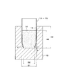
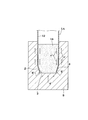
試験に用いた鋼管杭のテーパー部の形態は、図7A,図7Bに示す第7実施形態のテーパー部4に突起16gを有する鋼管杭1Gと、比較例として図8A及び図8Bに示すテーパー部4に突起を備えていない形態の鋼管杭17について試験した。試験に用いた両試験体の鋼管杭1G,17は、テーパー部4に等角度間隔をおいて4つ掘削用ビット6を備えている。
試験に用いた両試験体の鋼管杭1G,17の主な寸法は、その鋼管杭1G,17における外径が一定の定径部9の外径寸法D1が、いずれも1000mmである。テーパー部4の鋼管杭1G,17の中心軸線C方向の長さH1は、いずれもH1=0.5D1であり、テーパー部4の外径寸法D2と定径部9の外形寸法D1との関係は、D2=0.9D1である。また、テーパー部4に突起16gを設けた本実施形態の鋼管杭1Gでは、突起16gとして直径16mmの鉄筋を掘削ビット6の上端部に接続するように配置して、溶接により固定する。突起16gの高寸法さH2としては、H2=0.016D1であり、突起16gとしては鉄筋である。掘削ビット6に接続するように掘削ビット6の直上からテーパー部4の上端まで、突起16gの傾斜角δを45°としてテーパー部4に溶接により突起16gを固定し、鋼管杭1Gとした。
試験に用いた鋼管杭のテーパー部の形態は、図7A,図7Bに示す第7実施形態のテーパー部4に突起16gを有する鋼管杭1Gと、比較例として図8A及び図8Bに示すテーパー部4に突起を備えていない形態の鋼管杭17について試験した。試験に用いた両試験体の鋼管杭1G,17は、テーパー部4に等角度間隔をおいて4つ掘削用ビット6を備えている。
試験に用いた両試験体の鋼管杭1G,17の主な寸法は、その鋼管杭1G,17における外径が一定の定径部9の外径寸法D1が、いずれも1000mmである。テーパー部4の鋼管杭1G,17の中心軸線C方向の長さH1は、いずれもH1=0.5D1であり、テーパー部4の外径寸法D2と定径部9の外形寸法D1との関係は、D2=0.9D1である。また、テーパー部4に突起16gを設けた本実施形態の鋼管杭1Gでは、突起16gとして直径16mmの鉄筋を掘削ビット6の上端部に接続するように配置して、溶接により固定する。突起16gの高寸法さH2としては、H2=0.016D1であり、突起16gとしては鉄筋である。掘削ビット6に接続するように掘削ビット6の直上からテーパー部4の上端まで、突起16gの傾斜角δを45°としてテーパー部4に溶接により突起16gを固定し、鋼管杭1Gとした。
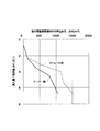
地盤は、一軸圧縮強度が5N/mm2の軟岩(泥岩)であり、この地盤から各鋼管杭1G,17の外径寸法D1の3倍の距離の深さに回転圧入する。施工時において、一定の定径部9の外径寸法D1(杭頭部側)の杭頭部の単位面積当たりの施工荷重(圧入力:kN/m2)と、前記外径寸法D1に対する貫入量(貫入比)とを計測して、これらの施工荷重と貫入量(貫入比)との関係について図10にグラフに示した。
図10に示すように、テーパー部4に突起16gを備えていない鋼管杭17の場合は、圧入力が最大645kN/m2であるのに対して、テーパー部4に突起16gを有する本実施形態の鋼管杭1Gの場合では、圧入力が最大363kN/m2であった。すなわち、約30%以上の施工荷重を低減することができることがわかる。
これにより、本発明のテーパー部4に突起16gを有する鋼管杭1Gの場合は、施工荷重を低減することができるため、カウンタウェイトを少なくできる。また、施工荷重が約30%以上低減できると、施工機械の能力を下げることができ、現存の施工機械では、例えば、1ランク下の小型の施工機械を用いて施工することができるため、施工コストを格段に低減することができる。
図10に示すように、テーパー部4に突起16gを備えていない鋼管杭17の場合は、圧入力が最大645kN/m2であるのに対して、テーパー部4に突起16gを有する本実施形態の鋼管杭1Gの場合では、圧入力が最大363kN/m2であった。すなわち、約30%以上の施工荷重を低減することができることがわかる。
これにより、本発明のテーパー部4に突起16gを有する鋼管杭1Gの場合は、施工荷重を低減することができるため、カウンタウェイトを少なくできる。また、施工荷重が約30%以上低減できると、施工機械の能力を下げることができ、現存の施工機械では、例えば、1ランク下の小型の施工機械を用いて施工することができるため、施工コストを格段に低減することができる。
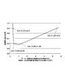
また、前記の各試験体の鋼管杭1G,17について、テーパー部4の外周面における鋼管杭1G,17の中心軸線C方向の平均磨耗量(%)について測定した結果のグラフを図11に示す。磨耗量の計測位置は、図11の上図の矢印で示すA、B、Cの3箇所で計測した結果を図11の下図に示す。
図11から、テーパー部4に突起16gを備えた鋼管杭1Gでは、テーパー部4に突起16gを備えていない鋼管杭17に比べて、テーパー部4の前端4a(グラフの0の位置)、先端部4の上端(グラフの0.5D1の位置)及びその中央(0.25D1の位置)で、平均磨耗量が半減以下に格段に低減している。さらには、テーパー部4の先端4a(グラフ0の位置)とテーパー部4の上端(0.5D1の位置)との位置では、鋼管杭1Gは、ほとんど磨耗していないのに対して、突起を備えていない形態の鋼管杭17では、テーパー部4の前端4aで2%弱、テーパー部4の上端で3%強の平均磨耗量を生じていることがわかる。
なお、前記の平均磨耗量(%)は、テーパー部4の元の板厚を1とした場合の値(比)である。また、前記の平均磨耗量(%)は、複数の試験体の磨耗量を平均した値である。
図11から、テーパー部4に突起16gを備えた鋼管杭1Gでは、テーパー部4に突起16gを備えていない鋼管杭17に比べて、テーパー部4の前端4a(グラフの0の位置)、先端部4の上端(グラフの0.5D1の位置)及びその中央(0.25D1の位置)で、平均磨耗量が半減以下に格段に低減している。さらには、テーパー部4の先端4a(グラフ0の位置)とテーパー部4の上端(0.5D1の位置)との位置では、鋼管杭1Gは、ほとんど磨耗していないのに対して、突起を備えていない形態の鋼管杭17では、テーパー部4の前端4aで2%弱、テーパー部4の上端で3%強の平均磨耗量を生じていることがわかる。
なお、前記の平均磨耗量(%)は、テーパー部4の元の板厚を1とした場合の値(比)である。また、前記の平均磨耗量(%)は、複数の試験体の磨耗量を平均した値である。
また、各試験体の鋼管杭1G,17におけるテーパー部4の外周面2における半径方向の位置(元の形状)に対する半径方向の平均変形量(%)について、図12の上図にD,E,Fで示す位置で計測した結果のグラフを図12の下図に示す。本発明の突起16gを有するテーパー部4の計測点は、突起16gに沿って計測した。鋼管杭の1G,17の半径方向の中心側(内側)に湾曲してへこむように変形した場合を+(プラス)変形とし、鋼管杭の1G,17の半径方向の外側に湾曲して膨らむように変形した場合を-(マイナス)変形として表示している。
図12から、テーパー部4に突起を備えていない鋼管杭17では、そのテーパー部4は、軸方向の先端側では中心軸線Cに向かってへこんで変形し、軸方向の基端側(大径側)では、膨らむようになる。軸方向においてテーパー部4の変形形態が逆転している(へこんだ後、膨らむ)のに対して、本発明の鋼管杭1Gでは、テーパー部4は、杭軸方向で微小な膨らみを生じているだけであることがわかる。
図11及び図12のグラフから、テーパー部4に突起16gを有する本発明の鋼管杭1Gの場合は、テーパー部4に突起16gを備えていない形態の鋼管杭17に比べて、テーパー部4の磨耗量及び変形量が格段に改善されることがわかる。
テーパー部4に突起16gを設けた場合は、当然、突起16gを設けた部分の板厚は厚くなり剛性が高くなると共にテーパー部4全体の剛性も向上する。
図12から、テーパー部4に突起を備えていない鋼管杭17では、そのテーパー部4は、軸方向の先端側では中心軸線Cに向かってへこんで変形し、軸方向の基端側(大径側)では、膨らむようになる。軸方向においてテーパー部4の変形形態が逆転している(へこんだ後、膨らむ)のに対して、本発明の鋼管杭1Gでは、テーパー部4は、杭軸方向で微小な膨らみを生じているだけであることがわかる。
図11及び図12のグラフから、テーパー部4に突起16gを有する本発明の鋼管杭1Gの場合は、テーパー部4に突起16gを備えていない形態の鋼管杭17に比べて、テーパー部4の磨耗量及び変形量が格段に改善されることがわかる。
テーパー部4に突起16gを設けた場合は、当然、突起16gを設けた部分の板厚は厚くなり剛性が高くなると共にテーパー部4全体の剛性も向上する。
テーパー部4の外周面2に前記のように突起16gを設けた鋼管杭1Gでは、次の(1)~(4)のような効果を期待することができる。
(1)杭回転圧入施工時に、突起16gにより、テーパー部4の外周面2付近の地盤(土)を効率よく積極的に破壊し(せん断破壊し)、杭の回転挿入を容易にすることができる。
(2)本来テーパー部4で、地盤の抵抗によって発生する摩耗や変形を、突起16g部分が担うことで、杭支持力性能を発揮するための重要な部材であるテーパー部4の摩耗・変形を抑えることができ、杭体の健全性(安全性)を大きく向上させることができる。
(3)掘削ビット6の直上面に接続して突起16gを設けることで、掘削ビット6で掘削した土砂が、突起16gに沿って上方に流れるため、杭施工の抵抗が減少する。
(4)突起16gは、鋼管杭1Gの中心軸線C方向の軸線に交差するように取付け角度δを有して設けられていることで、杭を回転させて施工する際に、突起16gによりせん断破壊した土を、突起16gにより上方へ流動させる効果を発現させることができる。さらには、杭を施工する時の地盤抵抗を低減することができる。
本試験では、第7実施形態の鋼管杭1Gを用いて説明したが、他の実施形態の鋼管杭1A~1Fを用いても同様の効果を得ることができる。
(1)杭回転圧入施工時に、突起16gにより、テーパー部4の外周面2付近の地盤(土)を効率よく積極的に破壊し(せん断破壊し)、杭の回転挿入を容易にすることができる。
(2)本来テーパー部4で、地盤の抵抗によって発生する摩耗や変形を、突起16g部分が担うことで、杭支持力性能を発揮するための重要な部材であるテーパー部4の摩耗・変形を抑えることができ、杭体の健全性(安全性)を大きく向上させることができる。
(3)掘削ビット6の直上面に接続して突起16gを設けることで、掘削ビット6で掘削した土砂が、突起16gに沿って上方に流れるため、杭施工の抵抗が減少する。
(4)突起16gは、鋼管杭1Gの中心軸線C方向の軸線に交差するように取付け角度δを有して設けられていることで、杭を回転させて施工する際に、突起16gによりせん断破壊した土を、突起16gにより上方へ流動させる効果を発現させることができる。さらには、杭を施工する時の地盤抵抗を低減することができる。
本試験では、第7実施形態の鋼管杭1Gを用いて説明したが、他の実施形態の鋼管杭1A~1Fを用いても同様の効果を得ることができる。
本発明において、硬質地盤とは岩盤を言い、その岩盤は、軟岩系岩盤(一軸圧縮強度~20MPa未満)と硬岩系岩盤(一軸圧縮強度:20MPa以上)とに分けられるが、本発明の先端テーパー部突起付きの鋼管杭1A~1Gは、掘削ビット6を備えている形態では、いずれの岩盤にも適用可能である。
前記のテーパー部4の外周面2およびテーパー部4の内周面3の杭の長さ方向の断面形態としては、杭長手方向の片側の断面形態として、外側および内側が、図1Bに示すように直線状であってもよく、図示を省略するが、曲線状であってもよい。テーパー部4の外周面2およびテーパー部4の内周面3の杭の長さ方向の断面形態としては、杭中心軸上から半径方向で外側に向かって凸(半径方向で内側に向かって凹)でも、杭中心軸上から半径方向で内側に向かって凸(半径方向で外側に向かって凹)でもよい。突起16a~16e,16gを設ける場合には、テーパー部4の外周面2に直接設置する。
次に、本発明のテーパー部4の寸法及び作用について説明する。ここで、図13A及び図13Bは、突起a~16e,16gを省略した図である。
前記のように、鋼管杭1A~1Gの先端4a側を縮径したテーパー部4を設けることにより、図13Bの矢印C1及び図15の矢印C1で示すように、積極的に土を杭の外側に流れるようにすることで、管内に流入する土を減らすことが可能となる。また、テーパー部4の開口面積を減らすことで、図13Bの矢印C1及び図15の矢印C1で示すように、管内に流入する土を減らすと共に半径方向に拡散させることが可能となる。これらにより、杭先端部が管内土による閉塞の発生を抑制し、管内土と杭1A~1Gの内周面3との摩擦を軽減し、杭押込み力の軽減を図ることを可能にしている。
前記のように、鋼管杭1A~1Gの先端4a側を縮径したテーパー部4を設けることにより、図13Bの矢印C1及び図15の矢印C1で示すように、積極的に土を杭の外側に流れるようにすることで、管内に流入する土を減らすことが可能となる。また、テーパー部4の開口面積を減らすことで、図13Bの矢印C1及び図15の矢印C1で示すように、管内に流入する土を減らすと共に半径方向に拡散させることが可能となる。これらにより、杭先端部が管内土による閉塞の発生を抑制し、管内土と杭1A~1Gの内周面3との摩擦を軽減し、杭押込み力の軽減を図ることを可能にしている。
杭先端部にテーパー部4を設けることで、テーパー部4の内周面3に作用する土の抵抗は増大するが、回転圧入施工する工法を採用することで、杭周面の摩擦の増大を抑制することが可能である利点も生かしている。さらに突起16a~16e,16gを設けることでテーパー部4の内周面3に作用する土を内周面3よりも上方に移動するよう促進することができ、土の抵抗を低減している。
テーパー部4の先端4aの外径寸法D2と鋼管杭の外径が一定の定径部の外径寸法D1との比率である縮径率が小さく、テーパー部4の杭長手方向(軸方向)の長さH1と、外径が一定の定径部の外径寸法D1との比率(H1/D1)が小さくなりすぎると(換言すると、テーパー部4のテーパー角θ(°)が大きくなりすぎると)、回転圧入施工時に、テーパー部4に作用する面圧による抵抗が高くなる。その結果、施工障害を生じる可能性がある。そこで、実施形態では、これらの比率を所定の範囲内に制限することで、良好な回転圧入施工性を図ることができるようにしている。本発明では、前記のテーパー部4の杭の長さ方向(鋼管杭の中心軸線C方向と同じ)の長さH1と、テーパー部4先端の外径寸法D2と、外径が一定の定径部の外径寸法D1と、テーパー角θとの間には、tanθ=(D1-D2)/2H1の関係がある。また施工時には、テーパー部4は、地盤に対して回転方向と貫入方向鉛直が組み合わされた動きをすることに加え、杭の貫入方向とテーパー角θを有する。これにより、地盤に対してせん断力および圧縮力を同時に作用させるとともに地盤を側方に押し広げる効果が発揮される。したがって、効率良く地盤を乱すことができ、テーパー部4の施工時の抵抗は小さくなる。
テーパー部4を設けることで、杭底面の投影面積が増加するため、支持層に貫入させた場合、テーパー部4により、確実な支持力を得ることができる。先端4aが開口している開端杭で支持力確保のためには、管内閉塞が不十分であっても確実な支持力を発揮することができる。テーパー部4の底面投影面積の部分で高い圧縮荷重を負担できるため、鋼管杭1A~1Gは、通常のストレートな開端杭を回転圧入施工して貫入させた場合よりも高い支持力を発揮することができる。
さらに、地盤の拘束圧が十分な硬質な地盤においては、鋼管杭1A~1Gは、確実に高い支持力を発揮する。したがって、先端4aが閉塞したストレートな鋼管杭を回転圧入施工によって貫入させた場合よりも高い支持力が期待できる。
鋼管杭1A~1Gを回転圧入施工する場合、その施工中に、地中で鋼管杭1A~1Gを上動および下動を交互に繰り返すことで、上動時に、管内の土が管の下方に落下し、下動時に落下した土が管外に押しのけられる。これにより、図15及び図16に示すように、管内の土の高さを下げることが可能となり、定径部9の内周面12と管内土14との接触面を少なくすることができる。この結果、内周面12と管内土14との摩擦が軽減されるので、さらに施工荷重を低減することが可能となる。
さらに、地盤の拘束圧が十分な硬質な地盤においては、鋼管杭1A~1Gは、確実に高い支持力を発揮する。したがって、先端4aが閉塞したストレートな鋼管杭を回転圧入施工によって貫入させた場合よりも高い支持力が期待できる。
鋼管杭1A~1Gを回転圧入施工する場合、その施工中に、地中で鋼管杭1A~1Gを上動および下動を交互に繰り返すことで、上動時に、管内の土が管の下方に落下し、下動時に落下した土が管外に押しのけられる。これにより、図15及び図16に示すように、管内の土の高さを下げることが可能となり、定径部9の内周面12と管内土14との接触面を少なくすることができる。この結果、内周面12と管内土14との摩擦が軽減されるので、さらに施工荷重を低減することが可能となる。
本発明では、テーパー部4の杭長手方向の長さH1と、外径が一定の定径部9の外径寸法D1との比率(H1/D1)が0.3~5.5に設定される。すなわち、H1/D1が0.3~5.5に設定される。
また、テーパー部先端の外径寸法D2と、鋼管杭の外径が一定の定径部9の外径寸法D1との比率(D2/D1)である縮径率(D2/D1)が、0.60~0.95の範囲となるように、外径寸法D2が外径寸法D1より小さく設定されている。
また、テーパー部先端の外径寸法D2と、鋼管杭の外径が一定の定径部9の外径寸法D1との比率(D2/D1)である縮径率(D2/D1)が、0.60~0.95の範囲となるように、外径寸法D2が外径寸法D1より小さく設定されている。
前記のようにH1/D1を0.3~5.5に設定した理由および鋼管杭1A~1Gの外径寸法D2を設定した理由について、図16~図20を参照して説明する。ここで、テーパー部4の形状は鋼管杭1A~1Gいずれも同じであるため、鋼管杭1Aを参照して説明する。
先ず、図19を参照して説明すると、縮径率(D2/D1)を0.9とした場合で、テーパー部4の中心軸線C方向の長さH1と、外径が一定である定径部9の外径寸法D1との比率(H1/D1)と、必要押し込み力比率(テーパー部4を有する鋼管杭1Aの必要押し込み力と、ストレートな鋼管杭10の必要押し込み力との比率)との関係を実験により調べたグラフである。
実験に用いた鋼管杭1Aは、定径部9の外径寸法(D1)が100mmであり、鋼管部分の厚み(t)が4.2mmであり、テーパー部4の先端4aの外径寸法(D2)が90mmである。また、全長に渡り外径寸法(D1)が一定のストレートな鋼管杭10の外径寸法(D1)および鋼管部分の厚み(t)は、前記の鋼管杭1Aと同じである。
先ず、図19を参照して説明すると、縮径率(D2/D1)を0.9とした場合で、テーパー部4の中心軸線C方向の長さH1と、外径が一定である定径部9の外径寸法D1との比率(H1/D1)と、必要押し込み力比率(テーパー部4を有する鋼管杭1Aの必要押し込み力と、ストレートな鋼管杭10の必要押し込み力との比率)との関係を実験により調べたグラフである。
実験に用いた鋼管杭1Aは、定径部9の外径寸法(D1)が100mmであり、鋼管部分の厚み(t)が4.2mmであり、テーパー部4の先端4aの外径寸法(D2)が90mmである。また、全長に渡り外径寸法(D1)が一定のストレートな鋼管杭10の外径寸法(D1)および鋼管部分の厚み(t)は、前記の鋼管杭1Aと同じである。
図19から、H1/D1が0.3の時、必要押し込み力比率は0.9であり、また、H1/D1が0.4の時、必要押し込み力比率は0.6であり、また、H1/D1が1.35の時、必要押し込み力比率は0.6であり、また、H1/D1が5.5の時、必要押し込み力比率は0.90であることがわかる。このことから、テーパー部4の中心軸線C方向の長さH1と、外径が一定の定径部9の外径寸法D1との比率(H1/D1)が0.3~5.5の時、すなわち、H1/D1が0.3~5.5の時に、必要押し込み力比率は、0.9以下になり、鋼管杭1Aは、図22Aに示すストレートな鋼管杭10に比べて少なくとも1割、必要押し込み力を低減することができることがわかる。
また、H1/D1が0.40~1.35の時に、必要押し込み力比率は、0.6以下になり、鋼管杭1Aでは、ストレートな鋼管杭10に比べて4割、必要押し込み力を低減することができることがわかる。
また、H1/D1が0.40~1.35の時に、必要押し込み力比率は、0.6以下になり、鋼管杭1Aでは、ストレートな鋼管杭10に比べて4割、必要押し込み力を低減することができることがわかる。
そして、図20には、実験値をプロットして結んだ曲線を示し、この図は、先端4aの外径寸法D2と定径部9の外径寸法D1との比率である縮径率(D2/D1)を横軸にとり、各種縮径率の鋼管杭1Aについて、必要押し込み力比率を実験により調べて比較したグラフである。
図20に示すように、縮径率(D2/D1)が0.60の時、必要押し込み力比率は0.9であり、縮径率(D2/D1)が0.75の時、必要押し込み力比率は0.6であり、縮径率(D2/D1)が0.92の時、必要押し込み力比率は0.60であり、縮径率(D2/D1)が0.95の時、必要押し込み力比率は0.90であることがわかる。
これらの図19および図20に示す下に凸のグラフから、縮径率(D2/D1)が0.60~0.95の範囲において、必要押し込み力比率が0.90以下に低減し、必要押し込み力を少なくとも10%低減することができる。また、縮径率(D2/D1)が0.75~0.92の範囲において、必要押し込み力比率が0.60以下になり、必要押し込み力が40%低減することができることがわかる。
したがって、H1/D1を0.3~5.5とし、縮径率(D2/D1)が0.60~0.95とするのが好ましく、より好ましくは、H1/D1を0.3~5.5とし、縮径率(D2/D1)を0.75~0.92の範囲にするのがよい。
これらの図19および図20に示す下に凸のグラフから、縮径率(D2/D1)が0.60~0.95の範囲において、必要押し込み力比率が0.90以下に低減し、必要押し込み力を少なくとも10%低減することができる。また、縮径率(D2/D1)が0.75~0.92の範囲において、必要押し込み力比率が0.60以下になり、必要押し込み力が40%低減することができることがわかる。
したがって、H1/D1を0.3~5.5とし、縮径率(D2/D1)が0.60~0.95とするのが好ましく、より好ましくは、H1/D1を0.3~5.5とし、縮径率(D2/D1)を0.75~0.92の範囲にするのがよい。
押し込み力比率が0.9以下に下がると、カウンタウェイト(錘)を大きく減らせることができる。例えば、必要押し込み力86t(トン),反力ウェイト66t(トン),回転圧入施工機械の重量20t(トン)の回転圧入施工設備の場合、必要押し込み力が10%低減できれば8.6t(トン)減とすることができ、カウンタウェイトを13%減らすことが可能になる。
また、図19に示すように、H1/D1が0.40~1.35であれば、必要押し込み力比率が0.6以下にできるため、さらにカウンタウェイトを軽減できることがわかる。このように、必要押し込み力比率を0.6以下にすると、回転圧入施工機を一段下の小型の回転圧入施工機を用いて杭を回転圧入施工することができるので、特に望ましい。
また、図19に示すように、H1/D1が0.40~1.35であれば、必要押し込み力比率が0.6以下にできるため、さらにカウンタウェイトを軽減できることがわかる。このように、必要押し込み力比率を0.6以下にすると、回転圧入施工機を一段下の小型の回転圧入施工機を用いて杭を回転圧入施工することができるので、特に望ましい。
鋼管杭1Aを地盤に回転圧入した場合の抵抗低減メカニズムについて、図21A及び図21Bを参照して説明する。図21Bでは、鋼管杭1Aに設けれている突起16a及び掘削ビット6を省略した図を示す。
図21Aのストレート鋼管杭10および図21Bの鋼管杭1Aにおいて、aおよびa´を先端閉塞部での抵抗、bを先端外周面での抵抗、b´をテーパー部4による抵抗、cおよびc´をテーパー部4の外周面2の摩擦による抵抗とした場合、また、τを管内土による抵抗とする。
このような場合、図21Aにおいて、a=τとなるから、図21Bのように、H1/D1を小さくする(換言すると、テーパー部4のテーパー角(θ)を大きくする)と、先端4aによる抵抗b´が増加するようになる。また、図21Bにおいて、テーパー部4の縮径率を増加させると、先端閉塞部での抵抗a´が減少し、テーパー部4による抵抗b´が増加するようになり、図21A及び図21Bに示すように、水平な部分(縮径率で70%程度~80%程度の範囲)は、これらの抵抗の増減の効果により、釣り合う範囲である。
図21Aのストレート鋼管杭10および図21Bの鋼管杭1Aにおいて、aおよびa´を先端閉塞部での抵抗、bを先端外周面での抵抗、b´をテーパー部4による抵抗、cおよびc´をテーパー部4の外周面2の摩擦による抵抗とした場合、また、τを管内土による抵抗とする。
このような場合、図21Aにおいて、a=τとなるから、図21Bのように、H1/D1を小さくする(換言すると、テーパー部4のテーパー角(θ)を大きくする)と、先端4aによる抵抗b´が増加するようになる。また、図21Bにおいて、テーパー部4の縮径率を増加させると、先端閉塞部での抵抗a´が減少し、テーパー部4による抵抗b´が増加するようになり、図21A及び図21Bに示すように、水平な部分(縮径率で70%程度~80%程度の範囲)は、これらの抵抗の増減の効果により、釣り合う範囲である。
本発明の鋼管杭1Aのテーパー部4は前記のような作用を有し、さらにテーパー部4に突起16aを備えることにより、テーパー部4と地盤との接触による抵抗を、テーパー部4に接触する土を積極的にせん断破壊して軽減することができる。また、突起16aの傾斜角δを30°~50°と、通常の地盤の内部摩擦角φに合わせることで効率よく破砕することができる。
前記の掘削方向A1に向かって尖らせた尖り部5としては、掘削方向A1に向かって尖らせた尖り部5とすればよい。前記の場合に、杭の周方向に尖らせた部分を備えていてもよい。
これらの形態のように、テーパー部4の先端4aに、掘削方向A1に向かって尖らせた尖り部5を設けると、地盤が硬質であっても、掘削ビット6と尖り部5により、あるいは、テーパー部4の掘削ビット6を兼ねた尖り部5により、杭打設施工時において、先端部地盤を破壊または掘削しながら、鋼管杭を地盤に貫入させることができる。
これらの形態のように、テーパー部4の先端4aに、掘削方向A1に向かって尖らせた尖り部5を設けると、地盤が硬質であっても、掘削ビット6と尖り部5により、あるいは、テーパー部4の掘削ビット6を兼ねた尖り部5により、杭打設施工時において、先端部地盤を破壊または掘削しながら、鋼管杭を地盤に貫入させることができる。
前記のような本発明の鋼管杭1A~1G又は突起を有していない鋼管杭17を施工する場合には、従来と同様、鋼管杭に回転力および押込み力を付与する回転圧入工法によって地盤に圧入すればよい。図9に示すような回転圧入施工機7により、先端テーパー部付きの鋼管杭17等の周側面を把持して回転圧入施工した場合では、従来の鋼管杭10、すなわち、鋼管杭の外径寸法D1およびその厚みtが同じであるストレートな鋼管杭10を施工する場合に比べて、本発明の鋼管杭1A~1Gは、図17に示す押し込み力当たりの貫入量、図18に示す先端荷重度(kN/m2)の点で優れていることがわかる。
さらに説明すると、図17には、図16に示すように外径寸法D1,テーパー部4先端の外径寸法D2の杭を用いた施工時の施工荷重である杭の閉塞断面積当りの押込み力(kN/m2)-貫入量/杭径(H2/D1)の関係が示されている。図22Aに示すようなストレートな鋼管杭(図17では、ストレート杭と表記した)に比べて、本発明の鋼管杭1A~1Gでは、貫入量が大きいことがわかる。
また、図18には、硬質地盤中に鋼管を外径寸法D1の3倍の長さ分、回転圧入施工した後に、静的に荷重をかけた際の、先端荷重度(kN/m2)-先端沈下量/杭径(D1)の関係が示されている。この図18から分かるように、ストレート杭に比べて、本発明の鋼管杭1A~1Gでは、先端荷重度が大きく、高い支持力が発揮されていることがわかる。
また、図18には、硬質地盤中に鋼管を外径寸法D1の3倍の長さ分、回転圧入施工した後に、静的に荷重をかけた際の、先端荷重度(kN/m2)-先端沈下量/杭径(D1)の関係が示されている。この図18から分かるように、ストレート杭に比べて、本発明の鋼管杭1A~1Gでは、先端荷重度が大きく、高い支持力が発揮されていることがわかる。
本発明の鋼管杭1A~1G又は突起を備えていない鋼管杭17を施工する場合には、軟質地盤下の支持層まで貫入したり、硬質地盤を含む地盤に回転圧入すればよい。
本発明の鋼管杭1A~1Gを施工する場合に、施工途中で、地中で鋼管杭1A~1Gを上下動させることで、鋼管杭内の土(管内土)の高さを下げるようにすると、図15及び図16に示すように、鋼管杭1A~1G内における管内土と内周面12との付着面積が少なくなる。これにより、付着面積が少なくなった分、抵抗が少なくなり、施工機械の負担を軽減し、効率よく施工することができる。
鋼管杭1A~1Gを上下動させる手段としては、回転圧入施工機7により先端テーパー部突起付きの鋼管杭1A~1G等を把持した状態で、回転圧入施工機7における液圧式等の伸縮式ジャッキ13を伸縮させる。これにより、容易に鋼管杭1A~1Gを上下動させることができる。
また、鋼管杭1A~1Gの施工法において、鋼管杭1A~1Gのテーパー部4を支持層内において最終的に打止める際に、鋼管杭1A~1Gを逆回転して、突起16a~16e,16gによりテーパー状外周面付近の土(砕石等を含むずり)を下方に押し込むようにする。この結果、突起16a~16e,16gにより、テーパー状外周面付近の土(砕石等を含むずり)を下方に押し込んで、杭下面側の支持層を密にして、杭を支持させることができる。
鋼管杭1A~1Gを上下動させる手段としては、回転圧入施工機7により先端テーパー部突起付きの鋼管杭1A~1G等を把持した状態で、回転圧入施工機7における液圧式等の伸縮式ジャッキ13を伸縮させる。これにより、容易に鋼管杭1A~1Gを上下動させることができる。
また、鋼管杭1A~1Gの施工法において、鋼管杭1A~1Gのテーパー部4を支持層内において最終的に打止める際に、鋼管杭1A~1Gを逆回転して、突起16a~16e,16gによりテーパー状外周面付近の土(砕石等を含むずり)を下方に押し込むようにする。この結果、突起16a~16e,16gにより、テーパー状外周面付近の土(砕石等を含むずり)を下方に押し込んで、杭下面側の支持層を密にして、杭を支持させることができる。
本発明の鋼管杭1A~1G等の鋼管本体部分を製作方法の一例としては、1本の鋼管杭のテーパー部を、冷間曲げ成形により形成するように製作してもよい。また、冷間プレス成型によりテーパー部を形成するように製作してもよい。あるいは帯状鋼板を扇状にしてその扇状の突起付き鋼板を冷間曲げによりテーパー状に加工して両側縁部を溶接により接合する。そして、その外径部が接続すべき鋼管とほぼ同じ外径のテーパー状の短管を製作し、そのテーパー状の短管の上端部を、1本の鋼管のテーパー部に溶接により固定して鋼管杭本体を製作してもよい。また、1本の鋼管のテーパー部を、塑性加工して、テーパー部を有する鋼管杭本体を製作してもよい。このような各種の形態のテーパー部に掘削ビットを備えたホルダーを固定すると共に突起を溶接等により設けるようにして、先端テーパー部突起付きの鋼管杭等を製作するようにすればよい。片面突起付き帯状鋼板を、扇状の突起付き鋼板とし、テーパー状の短管を製作し、そのテーパー状の短管の上端部を、1本の鋼管のテーパー部に溶接により固定することで、先端テーパー部突起付きの鋼管杭等を製作するようにしてもよい。
A1 掘削方向C 中心軸線
C2 突起の延在方向の中心軸線
D1 定径部の外形寸法
D2 前端の外形寸法
1A,1B,1C,1D,1E,1F,1G 鋼管杭
2 外周面
3 内周面
4 テーパー部(先端部)
4a 先端(前端)
5,5b 尖り部
6 掘削ビット
8 支持層
9 定径部
15 地盤
16a~16e,16g 突起
16e 突起の下端
C2 突起の延在方向の中心軸線
D1 定径部の外形寸法
D2 前端の外形寸法
1A,1B,1C,1D,1E,1F,1G 鋼管杭
2 外周面
3 内周面
4 テーパー部(先端部)
4a 先端(前端)
5,5b 尖り部
6 掘削ビット
8 支持層
9 定径部
15 地盤
16a~16e,16g 突起
16e 突起の下端
Claims (15)
- 掘削方向の前端が開口し、かつ、中空である鋼管杭であって、
外径寸法が一定である定径部と、前記前端に向かって内形寸法及び外形寸法が漸次小さくなる先端部とを備え;
前記先端部の外周面に、前記前端から後端に向かって一部または全体に延在し、かつ、前記先端部の半径方向外方に突出する突起が設けられている;
ことを特徴とする鋼管杭。 - 前記突起が、前記先端部の前記外周面の周方向に間隔をあけて複数設けられている
ことを特徴とする請求項1に記載の鋼管杭。 - 前記突起の前記後端側が前記定径部及び前記先端部の回転方向の後方になるように、前記突起が傾斜している
ことを特徴とする請求項1または請求項2に記載の鋼管杭。 - 前記突起が前記先端部の中心軸線に対して周方向に傾斜して配置され、
前記中心軸線に直角な面と前記突起の延在方向の中心軸線とのなす角が、20°~70°である
ことを特徴とする請求項1または請求項2に記載の鋼管杭。 - 前記突起が、前記定径部の外形寸法よりも、前記先端部の前記半径方向の内側に位置するように、前記突起の高さが規定されている
ことを特徴とする請求項1または請求項2に記載の鋼管杭。 - 前記前端の周方向に間隔をあけて掘削ビットが複数設けられている
ことを特徴とする請求項2に記載の鋼管杭。 - 前記突起の下端が、前記掘削ビットの上面の直上に位置している
ことを特徴とする請求項6に記載の鋼管杭。 - 前記掘削ビットが、前記定径部の外形寸法よりも、前記先端部の前記半径方向の内側に配置されている
ことを特徴とする請求項6に記載の鋼管杭。 - 前記定径部の外形寸法に対する前記先端部の長さ方向の高さ寸法の比が、0.3~5.5である
ことを特徴とする請求項1に記載の鋼管杭。 - 前記定径部の外径寸法に対する前記前端の外径寸法の比が、0.60~0.95であることを特徴とする請求項1に記載の鋼管杭。
- 前記先端部に、前記前端から突出し前記掘削方向に向かって尖った尖り部が設けられている
ことを特徴とする請求項1に記載の鋼管杭。 - 請求項1に記載の鋼管杭を用いた鋼管杭の施工方法であって、
前記鋼管杭に回転力および押込み力を付与する回転圧入工法によって地盤に圧入する際に、前記突起により前記地盤をせん断破壊しながら前記鋼管杭を圧入する
ことを特徴とする鋼管杭の施工方法。 - 硬質地盤を含む地盤に前記鋼管杭を回転圧入する
ことを特徴とする請求項12に記載の鋼管杭の施工方法。 - 施工途中において、地中で前記鋼管杭を回転させながら、あるいは回転を加えずに、または、それらを組合せながら上下動させることで、前記鋼管杭内の土の高さを下げる
ことを特徴とする請求項12に記載の鋼管杭の施工方法。 - 前記鋼管杭の前記先端部を支持層内において最終的に打止める際に、前記鋼管杭を逆回転して、前記突起により前記先端部の外周面付近の土を下方に押し込む
ことを特徴とする請求項12に記載の鋼管杭の施工方法。
Priority Applications (1)
| Application Number | Priority Date | Filing Date | Title |
|---|---|---|---|
| JP2011542603A JP4988068B2 (ja) | 2010-07-05 | 2011-07-01 | 鋼管杭及びその施工方法 |
Applications Claiming Priority (2)
| Application Number | Priority Date | Filing Date | Title |
|---|---|---|---|
| JP2010-153290 | 2010-07-05 | ||
| JP2010153290 | 2010-07-05 |
Publications (1)
| Publication Number | Publication Date |
|---|---|
| WO2012005197A1 true WO2012005197A1 (ja) | 2012-01-12 |
Family
ID=45441176
Family Applications (1)
| Application Number | Title | Priority Date | Filing Date |
|---|---|---|---|
| PCT/JP2011/065218 Ceased WO2012005197A1 (ja) | 2010-07-05 | 2011-07-01 | 鋼管杭及びその施工方法 |
Country Status (3)
| Country | Link |
|---|---|
| JP (1) | JP4988068B2 (ja) |
| TW (1) | TWI461589B (ja) |
| WO (1) | WO2012005197A1 (ja) |
Cited By (3)
| Publication number | Priority date | Publication date | Assignee | Title |
|---|---|---|---|---|
| JP2018193671A (ja) * | 2017-05-12 | 2018-12-06 | 株式会社テクト | あと施工アンカー打込み装置及びアンカー施工方法 |
| CN112459050A (zh) * | 2020-11-12 | 2021-03-09 | 中交一公局集团有限公司 | 高水位复杂地质区咬合桩硬切割成桩施工方法 |
| JPWO2022149421A1 (ja) * | 2021-01-06 | 2022-07-14 |
Families Citing this family (2)
| Publication number | Priority date | Publication date | Assignee | Title |
|---|---|---|---|---|
| CN112376557A (zh) * | 2020-12-01 | 2021-02-19 | 宁波中淳高科股份有限公司 | 连锁混凝土预制桩沉桩用土体切削引导装置及其使用方法 |
| JP7846328B2 (ja) * | 2021-11-25 | 2026-04-15 | 日本製鉄株式会社 | 鋼管杭 |
Citations (7)
| Publication number | Priority date | Publication date | Assignee | Title |
|---|---|---|---|---|
| JPS5540053U (ja) * | 1978-09-08 | 1980-03-14 | ||
| JPS59156376U (ja) * | 1983-04-04 | 1984-10-20 | 株式会社リコー | アダプタ−取付機構 |
| JPH01127718A (ja) * | 1987-11-13 | 1989-05-19 | Kawasaki Steel Corp | ドリル鋼管杭 |
| JP2003003465A (ja) * | 2001-06-20 | 2003-01-08 | Norio Moriya | テーパー基礎杭 |
| JP2007113387A (ja) * | 2005-09-22 | 2007-05-10 | Rokuro Unno | 先端開放型既製杭及びそれに使用される掘削ヘッド |
| JP2007284866A (ja) * | 2006-04-12 | 2007-11-01 | Nippon Steel Corp | 回転圧入鋼管杭及び鋼管杭を用いた圧入工法 |
| WO2010116758A1 (ja) * | 2009-04-10 | 2010-10-14 | 新日本製鐵株式会社 | 鋼管杭 |
Family Cites Families (1)
| Publication number | Priority date | Publication date | Assignee | Title |
|---|---|---|---|---|
| JPS6171628U (ja) * | 1984-10-18 | 1986-05-15 |
-
2011
- 2011-07-01 WO PCT/JP2011/065218 patent/WO2012005197A1/ja not_active Ceased
- 2011-07-01 JP JP2011542603A patent/JP4988068B2/ja active Active
- 2011-07-04 TW TW100123493A patent/TWI461589B/zh not_active IP Right Cessation
Patent Citations (7)
| Publication number | Priority date | Publication date | Assignee | Title |
|---|---|---|---|---|
| JPS5540053U (ja) * | 1978-09-08 | 1980-03-14 | ||
| JPS59156376U (ja) * | 1983-04-04 | 1984-10-20 | 株式会社リコー | アダプタ−取付機構 |
| JPH01127718A (ja) * | 1987-11-13 | 1989-05-19 | Kawasaki Steel Corp | ドリル鋼管杭 |
| JP2003003465A (ja) * | 2001-06-20 | 2003-01-08 | Norio Moriya | テーパー基礎杭 |
| JP2007113387A (ja) * | 2005-09-22 | 2007-05-10 | Rokuro Unno | 先端開放型既製杭及びそれに使用される掘削ヘッド |
| JP2007284866A (ja) * | 2006-04-12 | 2007-11-01 | Nippon Steel Corp | 回転圧入鋼管杭及び鋼管杭を用いた圧入工法 |
| WO2010116758A1 (ja) * | 2009-04-10 | 2010-10-14 | 新日本製鐵株式会社 | 鋼管杭 |
Cited By (4)
| Publication number | Priority date | Publication date | Assignee | Title |
|---|---|---|---|---|
| JP2018193671A (ja) * | 2017-05-12 | 2018-12-06 | 株式会社テクト | あと施工アンカー打込み装置及びアンカー施工方法 |
| CN112459050A (zh) * | 2020-11-12 | 2021-03-09 | 中交一公局集团有限公司 | 高水位复杂地质区咬合桩硬切割成桩施工方法 |
| JPWO2022149421A1 (ja) * | 2021-01-06 | 2022-07-14 | ||
| JP7279855B2 (ja) | 2021-01-06 | 2023-05-23 | Jfeスチール株式会社 | 杭、杭の施工方法、構造物、構造物の構築方法、杭の設計方法及び杭の製造方法 |
Also Published As
| Publication number | Publication date |
|---|---|
| TWI461589B (zh) | 2014-11-21 |
| JP4988068B2 (ja) | 2012-08-01 |
| JPWO2012005197A1 (ja) | 2013-09-02 |
| TW201207198A (en) | 2012-02-16 |
Similar Documents
| Publication | Publication Date | Title |
|---|---|---|
| JP4988068B2 (ja) | 鋼管杭及びその施工方法 | |
| WO1999046449A1 (en) | Rotation buried pile and execution management method therefor | |
| JP6449243B2 (ja) | 螺旋状羽根付鋼管杭及び合成杭並びに合成杭の造成方法 | |
| JP2009167752A (ja) | 地盤強化用鋼管、及びそれを使用した地盤強化方法 | |
| US10837154B2 (en) | Coupler for soil nail and method of emplacing same | |
| US10072389B2 (en) | Coupler for soil nail and method of emplacing same | |
| JP3643303B2 (ja) | 回転圧入鋼管杭 | |
| JP5177065B2 (ja) | 鋼管杭及びその施工方法 | |
| JP2007032044A (ja) | 基礎杭の支持構造および鋼管杭 | |
| JP4863120B2 (ja) | 基礎杭 | |
| JP4099199B2 (ja) | 先端開放型既製杭及びそれに使用される掘削ヘッド | |
| JP4095098B2 (ja) | 基礎杭施工用掘削機の拡大翼拡径状態確認方法 | |
| JP4943363B2 (ja) | 鋼管杭およびその施工方法 | |
| JP5177064B2 (ja) | 基礎杭及びその施工方法 | |
| JP4635114B2 (ja) | 鋼管杭 | |
| JP4853132B2 (ja) | 基礎杭の施工方法 | |
| JP5499335B2 (ja) | 鋼管杭およびその鋼管杭を用いた支持構造と施工方法 | |
| JP5413336B2 (ja) | 鋼管杭の製造方法および杭の施工方法 | |
| JP3932978B2 (ja) | 杭 | |
| JP2002356847A (ja) | 基礎杭の支持構造および基礎杭の施工方法 | |
| JP2001303563A (ja) | ソイルセメント合成コンクリート杭の造成方法 | |
| JP5813595B2 (ja) | スパイラル杭の推進補助手段及び推進方法 | |
| JP4005106B1 (ja) | 基礎杭施工用拡径掘削機の掘削ヘッド | |
| JP2008057229A (ja) | 先端羽根付き拡径管及びそれを備えた先端羽根付き鋼管杭 | |
| JP2004278306A (ja) | 回転圧入鋼管杭 |
Legal Events
| Date | Code | Title | Description |
|---|---|---|---|
| WWE | Wipo information: entry into national phase |
Ref document number: 2011542603 Country of ref document: JP |
|
| 121 | Ep: the epo has been informed by wipo that ep was designated in this application |
Ref document number: 11803531 Country of ref document: EP Kind code of ref document: A1 |
|
| NENP | Non-entry into the national phase |
Ref country code: DE |
|
| 122 | Ep: pct application non-entry in european phase |
Ref document number: 11803531 Country of ref document: EP Kind code of ref document: A1 |