WO2011158309A1 - Unité intérieure pour appareil de conditionnement d'air, et appareil de conditionnement d'air - Google Patents
Unité intérieure pour appareil de conditionnement d'air, et appareil de conditionnement d'air Download PDFInfo
- Publication number
- WO2011158309A1 WO2011158309A1 PCT/JP2010/005168 JP2010005168W WO2011158309A1 WO 2011158309 A1 WO2011158309 A1 WO 2011158309A1 JP 2010005168 W JP2010005168 W JP 2010005168W WO 2011158309 A1 WO2011158309 A1 WO 2011158309A1
- Authority
- WO
- WIPO (PCT)
- Prior art keywords
- heat exchanger
- indoor unit
- noise
- air
- detection microphone
- Prior art date
Links
Images


Classifications
-
- F—MECHANICAL ENGINEERING; LIGHTING; HEATING; WEAPONS; BLASTING
- F24—HEATING; RANGES; VENTILATING
- F24F—AIR-CONDITIONING; AIR-HUMIDIFICATION; VENTILATION; USE OF AIR CURRENTS FOR SCREENING
- F24F1/00—Room units for air-conditioning, e.g. separate or self-contained units or units receiving primary air from a central station
- F24F1/0007—Indoor units, e.g. fan coil units
- F24F1/0018—Indoor units, e.g. fan coil units characterised by fans
- F24F1/0029—Axial fans
-
- F—MECHANICAL ENGINEERING; LIGHTING; HEATING; WEAPONS; BLASTING
- F24—HEATING; RANGES; VENTILATING
- F24F—AIR-CONDITIONING; AIR-HUMIDIFICATION; VENTILATION; USE OF AIR CURRENTS FOR SCREENING
- F24F1/00—Room units for air-conditioning, e.g. separate or self-contained units or units receiving primary air from a central station
- F24F1/0007—Indoor units, e.g. fan coil units
- F24F1/0043—Indoor units, e.g. fan coil units characterised by mounting arrangements
-
- F—MECHANICAL ENGINEERING; LIGHTING; HEATING; WEAPONS; BLASTING
- F24—HEATING; RANGES; VENTILATING
- F24F—AIR-CONDITIONING; AIR-HUMIDIFICATION; VENTILATION; USE OF AIR CURRENTS FOR SCREENING
- F24F13/00—Details common to, or for air-conditioning, air-humidification, ventilation or use of air currents for screening
- F24F13/24—Means for preventing or suppressing noise
- F24F2013/247—Active noise-suppression
Definitions
- the present invention is an indoor unit in which a fan and a heat exchanger are housed in a casing (indoor unit), and includes an silencer unit (speaker and microphone) for silencing the sound generated by the fan, And an air conditioner including the indoor unit.
- an air conditioner in which a fan and a heat exchanger are housed in a casing.
- an air conditioner comprising a main body casing having an air inlet and an air outlet, and a heat exchanger disposed in the main body casing, wherein the air outlet includes a plurality of small propellers.
- an air conditioner in which a fan unit having a fan arranged in the width direction of the air outlet is disposed” (see, for example, Patent Document 1).
- This air conditioner is provided with a fan unit at the air outlet to facilitate airflow direction control, and a fan unit having the same configuration is also provided at the suction port to improve the heat exchanger performance due to an increase in the air volume. I am doing so.
- a heat exchanger is provided on the upstream side of a fan unit (blower). Since the movable fan unit is provided on the air outlet side, the air flow changes due to the movement of the fan and the instability of the flow due to asymmetric suction causes a decrease in the air volume and a reverse flow. Furthermore, the air whose flow is disturbed flows into the fan unit. That is, there is a problem that the flow of air flowing into the outer peripheral part of the wing (propeller) of the fan unit that increases the flow velocity is disturbed, and the fan unit itself becomes a noise source (causes noise deterioration). there were.
- a casing in which a suction port is formed in the upper part and a blower outlet is formed in the lower part of the front surface, and an axial flow type or a slant provided on the downstream side of the suction port in the casing are provided.
- An air conditioner provided with a flow-type blower and a heat exchanger that is provided downstream of the blower in the casing and upstream of the blower outlet and exchanges heat between the air blown from the blower and the refrigerant.
- An "indoor unit” hereinafter referred to as an axial / mixed flow type indoor unit
- the present invention provides an air conditioner indoor unit that can further suppress noise by including a silencer unit (speaker and microphone) at a suitable position of the axial flow / diagonal flow type indoor unit as described above, and the air conditioner indoor unit. It aims at obtaining the air conditioner provided with the indoor unit.
- An indoor unit of an air conditioner according to the present invention includes a casing having a suction port formed in an upper portion thereof and a blower outlet formed in a lower side of a front surface portion, and an axial flow type or a slant provided on the downstream side of the suction port in the casing.
- a flow-type blower a heat exchanger that is provided on the downstream side of the blower in the casing and upstream of the blower outlet, heat exchange between the air blown from the blower and the refrigerant, and noise generated from the blower Noise detection device to detect, control sound output device that is provided downstream of the heat exchanger and outputs control sound for reducing noise, and provided on the downstream side of the heat exchanger to detect the silencing effect of the control sound And a control sound generation device that causes the control sound output device to output a control sound based on detection results of the noise detection device and the noise detection effect detection device.
- an air conditioner according to the present invention is provided with the indoor unit described above.
- the indoor unit of the air conditioner according to the present invention since the blower is provided on the upstream side of the heat exchanger, the flow of air flowing into the blower is less disturbed. For this reason, the indoor unit of the air conditioner according to the present invention can suppress noise generated from the blower.
- the indoor unit of the air conditioner according to the present invention further includes at least a control sound output device and a silencing effect detection device on the downstream side of the heat exchanger among the components of the silencing unit. For this reason, the indoor unit of the air conditioner according to the present invention can reduce the influence of the turbulence of the airflow generated in the blower on the silencing effect detection device, and until the control sound emitted from the control sound output device reaches the control point.
- the indoor unit of the air conditioner according to the present invention can perform highly accurate noise control by the silencer unit. Therefore, the present invention provides an indoor unit of an air conditioner that can further suppress noise than an axial flow / diagonal flow type indoor unit that can suppress noise from a blower, and an air conditioner including the indoor unit. be able to.
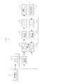
- FIG. 1 It is a longitudinal cross-sectional view which shows an example of the indoor unit of the air conditioner which concerns on Embodiment 1 of this invention. It is a block diagram which shows the signal processing apparatus which concerns on Embodiment 1 of this invention. It is the characteristic view which showed the coherence characteristic between both microphones by the installation position of a noise detection microphone and a silencing effect detection microphone. It is a longitudinal cross-sectional view which shows an example of the indoor unit of the air conditioner which concerns on Embodiment 2 of this invention. 4 is a schematic diagram for explaining a configuration example of a heat exchanger 5. FIG. It is a longitudinal cross-sectional view which shows an example of the indoor unit of the air conditioner which concerns on Embodiment 3 of this invention.
- Embodiment 1 FIG.
- a noise detection microphone corresponding to the noise detection device of the present invention
- a control speaker control sound output of the present invention
- a muffler effect detecting microphone corresponding to the muffler effect detecting device of the present invention
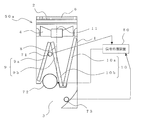
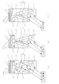
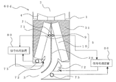
- FIG. 1 is a longitudinal sectional view showing an example of an indoor unit of an air conditioner according to Embodiment 1 of the present invention (hereinafter referred to as an indoor unit 40).
- FIG. 1 shows the left side of the drawing as the front side of the indoor unit 40. Based on FIG. 1, the structure of the indoor unit 40 is demonstrated.
- the indoor unit 40 supplies conditioned air to an air-conditioning target area such as a room by using a refrigeration cycle in which a refrigerant is circulated.
- FIG. 6, FIG. 6 to FIG. 14, FIG. 18, FIG. 20, FIG. 21, FIG. 24, and FIG. 25 show the left side of the figure as the front side of the indoor unit.
- the relationship of the size of each component may be different from the actual one.
- FIG. 1 the case where the indoor unit is a wall hanging type attached to the wall surface of the air-conditioning target area is shown as an example.
- the indoor unit 40 is mainly housed in the casing 1 in which a suction port 2 for sucking indoor air into the interior and a blower outlet 3 for supplying conditioned air to an air-conditioning target area are formed.
- the fan 4 sucks room air from the suction port 2 and blows out the conditioned air from the blower outlet 3, and is arranged in the air path from the suction port 2 to the fan 4 to exchange heat between the refrigerant and the room air.
- a heat exchanger 5 for producing And the air flow path (arrow A) is connected in the casing 1 by these components.
- the suction port 2 is formed in the upper part of the casing 1.
- the blower outlet 3 has an opening formed in the lower part of the casing 1 (more specifically, on the lower side of the front part of the casing 1).
- the fan 4 is disposed on the downstream side of the suction port 2 and on the upstream side of the heat exchanger 5, and is configured by, for example, an axial flow fan or a diagonal flow fan.
- the heat exchanger 5 is disposed on the leeward side of the fan 4. As this heat exchanger 5, for example, a fin tube heat exchanger or the like may be used.
- the suction port 2 is provided with a finger guard 6 and a filter 7.
- the blower outlet 3 is provided with a mechanism for controlling the blowing direction of the airflow, such as a vane (not shown).
- the fan 4 corresponds to the blower of the present invention.
- the indoor unit 40 includes a noise reduction unit including a noise detection microphone 71, a control speaker 72, a noise reduction effect detection microphone 73, and a signal processing device 80.
- the noise detection microphone 71 detects the operation sound (noise) of the indoor unit 40 including the blowing sound of the fan 4, and is attached to the downstream side of the heat exchanger 5.
- the muffler effect detection microphone 73 detects noise coming out of the air outlet 3 to detect the muffler effect, and forms the vicinity of the air outlet 3 on the downstream side of the heat exchanger 5 (for example, the air outlet 3 is formed). Nozzle part).
- a control speaker 72 that outputs a control sound for noise is provided on the side surface of the casing 1 (more specifically, on the lower side of the heat exchanger 5 and near the silencing effect detection microphone 73). Further, the control speaker 72 and the muffler effect detection microphone 73 are arranged so as to face the center of the air flow path from the wall of the casing 1.
- the installation position of the muffler effect detection microphone 73 is not limited to the nozzle portion of the air outlet 3 and may be an opening portion of the air outlet 3.
- the muffling effect detection microphone 73 may be attached to the lower part or the side part of the air outlet 3.
- the control speaker 72 is attached to the side surface of the casing 1, but the control speaker 72 may be attached to the front surface or the back surface of the casing 1.
- the noise detection microphone 71 is not necessarily provided on the downstream side of the heat exchanger 5, and the present invention can be achieved if the control speaker 72 and the muffler effect detection microphone 73 are provided on the downstream side of the heat exchanger 5. Can be implemented.
- the output signals of the noise detection microphone 71 and the silencing effect detection microphone 73 are input to a signal processing device 80 for generating a signal (control sound) for controlling the control speaker 72.
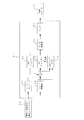
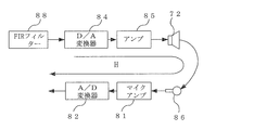
- FIG. 2 is a block diagram showing the signal processing apparatus according to Embodiment 1 of the present invention.
- the electric signal input from the noise detection microphone 71 is amplified by the microphone amplifier 81 and converted from an analog signal to a digital signal by the A / D converter 82.
- the electric signal input from the muffling effect detection microphone 73 is amplified by the microphone amplifier 81 and converted from an analog signal to a digital signal by the A / D converter 82.
- Each digital signal converted in this way is input to the FIR filter 88 and the LMS algorithm 89.
- the FIR filter 88 generates a control signal that is corrected so that the noise detected by the noise detection microphone 71 has the same amplitude and opposite phase as the noise when the noise reaches the control point where the muffler effect detection microphone 73 is installed. To do.
- This control signal is converted from a digital signal to an analog signal by the D / A converter 84, amplified by the amplifier 85, and emitted from the control speaker 72 as control sound.
- the operation of the indoor unit 40 configured as described above will be described.
- the flow of air in the indoor unit 40 will be briefly described.
- the indoor air flows into the indoor unit 40 from the suction port 2 formed in the upper part of the casing 1 by the fan 4.
- dust contained in the air is removed by the filter 7.
- This indoor air is heated or cooled by the refrigerant that is conducted through the heat exchanger 5 when passing through the heat exchanger 5 to become conditioned air.
- the conditioned air is blown out of the indoor unit 40 from the blowout port 3 formed in the lower part of the casing 1, that is, to the air-conditioning target area.
- the air that has passed through the filter 7 flows into the fan 4. That is, the air flowing into the fan 4 is less disturbed than the air flowing into the fan provided in the indoor unit of the conventional air conditioner (passed through the heat exchanger). For this reason, compared with the conventional air conditioner, the air passing through the outer peripheral part of the wing part of the fan 4 is less disturbed in the flow. Therefore, the air conditioner according to Embodiment 1 can suppress noise as compared with the indoor unit of a conventional air conditioner.
- the fan 4 is provided in the upstream of the heat exchanger 5, the indoor unit 40 is blown out from the blower outlet 3, compared with the indoor unit of the conventional air conditioner in which the fan is provided in the blower outlet.
- the generation of the swirling air flow and the generation of the wind speed distribution can be suppressed.
- there is no complicated structure such as a fan at the air outlet 3 it is easy to take measures against dew condensation caused by backflow or the like.
- the operation sound (noise) including the blowing sound of the fan 4 in the indoor unit 40 passes through the heat exchanger 5 and is detected by the noise detection microphone 71.
- the noise detected by the noise detection microphone 71 becomes a digital signal via the microphone amplifier 81 and the A / D converter 82 and is input to the FIR filter 88 and the LMS algorithm 89.
- the tap coefficient of the FIR filter 88 is updated sequentially by the LMS algorithm 89.
- h filter tap coefficient
- e error signal
- x filter input signal
- ⁇ step size parameter.
- the step size parameter ⁇ controls the filter coefficient update amount for each sampling.
- the digital signal having the tap coefficient updated by the LMS algorithm 89 and passing through the FIR filter 88 is converted to an analog signal by the D / A converter 84, amplified by the amplifier 85, and used as a control sound from the control speaker 72. It is discharged into the air flow path in the indoor unit 40.
- the noise propagated from the fan 4 through the air flow path is also heated.
- the sound after the control sound emitted from the control speaker 72 installed on the lower side of the exchanger 5 is interfered is detected.
- the signal detected by the silencing effect detection microphone 73 is handled as the error signal e of the LMS algorithm 89 described above. Then, feedback control is performed so that the error signal e approaches zero, and the tap coefficient of the FIR filter 88 is appropriately updated. As a result, noise in the vicinity of the outlet 3 can be suppressed by the control sound that has passed through the FIR filter 88.
- the coherence between the sound detected by the noise detection microphone 71 and the sound detected by the silencing effect detection microphone 73 needs to be high.
- the noise detection microphone 71 and the silencing effect detection microphone 73 are provided in a region where the airflow disturbance due to the rotation of the impeller of the fan 4 occurs (for example, in the indoor unit 40, the air flow path between the fan 4 and the heat exchanger 5).
- a pressure fluctuation component due to airflow turbulence which is a component other than the original noise, is detected, and the coherence between the two microphones decreases.
- the noise detection microphone 71 and the silencing effect detection microphone 73 are installed on the downstream side of the heat exchanger 5. Since the indoor unit 40 which is an axial flow / diagonal flow type indoor unit can install the fan 4 on the upstream side of the heat exchanger 5, the noise detection microphone 71, the silencing effect detection microphone 73, and the fan 4 are interposed between them. A heat exchanger 5 can be installed. When the noise detection microphone 71 and the silencing effect detection microphone 73 are installed in this way, the airflow turbulence generated by the fan 4 is suppressed by passing through the fins of the heat exchanger 5, and therefore the noise detection microphone 71 and the silencing effect detection microphone 73. Then, the influence by the turbulence of the airflow can be reduced. Therefore, the coherence between the noise detection microphone 71 and the silencing effect detection microphone 73 is increased, and a high silencing effect can be obtained.
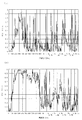
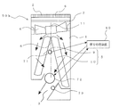
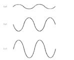
- FIG. 3 is a characteristic diagram showing the coherence characteristics between the two microphones depending on the installation positions of the noise detection microphone and the silencing effect detection microphone.
- FIG. 3A shows both microphones when the noise detection microphone 71 and the silencing effect detection microphone 73 are provided on the upstream side of the heat exchanger 5 (more specifically, between the fan 4 and the heat exchanger 5). It is the characteristic view which showed the coherence characteristic between.
- FIG. 3B is a characteristic diagram showing the coherence characteristics between the microphones when the noise detection microphone 71 and the silencing effect detection microphone 73 are provided on the downstream side of the heat exchanger 5. Comparing FIG. 3A and FIG.
- the noise detection microphone 71 and the silencing effect detection microphone 73 are arranged downstream of the heat exchanger. It can be seen that the coherence between both microphones is increased by providing it on the side.
- the distance from the installation position of the control speaker 72 to the installation position (control point) of the silencing effect detection microphone 73 is also affected by the silencing effect. That is, the length of the transmission path until the control sound emitted from the control speaker 72 reaches the control point (installation position of the mute effect detection microphone 73) also affects the muffling effect. More specifically, the amplitude characteristic and the phase characteristic of the control sound emitted from the control speaker 72 change in the transmission path until the control sound reaches the control point (the installation position of the silencing effect detection microphone 73). If the amplitude characteristic and the phase characteristic change in the transmission path and the control sound does not have the same amplitude and opposite phase as the noise, the noise reduction effect is reduced.
- the transmission path of the control sound is obtained in advance, and correction is applied in the process of generating the control sound.
- the problem of is solved.
- the transmission path becomes longer, the number of filter taps of the required transmission path becomes longer, and the calculation processing increases.
- the transmission path is long, such as when the sound speed changes due to changes in temperature or the like, the error between the calculated transmission path and the actual transmission path becomes large, and the silencing effect is reduced.
- control speaker 72 and the silencing effect detection microphone 73 close to each other.
- the transmission distance of the control sound can be shortened, and changes in the amplitude characteristic and the phase characteristic can be suppressed to a small level. That is, by installing the control speaker 72 and the muffler effect detection microphone 73 close to each other, it becomes possible to superimpose highly accurate sound waves, so that a high muffler effect can be obtained.
- the control speaker 72 is provided on the downstream side of the heat exchanger 5 where the silencing effect detection microphone 73 is installed. For this reason, the transmission path
- the indoor unit 40 which is an axial flow / diagonal flow type indoor unit can install the fan 4 on the upstream side of the heat exchanger 5, the fan 4 serving as a noise source is installed above the casing 1. be able to. For this reason, it is possible to lengthen the noise transmission path until the noise from the fan 4 is released from the air outlet 3. For this reason, the distance between the noise detection microphone 71 and the control speaker 72 can be increased by installing the control speaker 72 on the downstream side of the heat exchanger 5. In other words, it is possible to take a long calculation time until the control sound is generated for the sound detected by the noise detection microphone 71, so that it is not necessary to increase the calculation speed. Therefore, since the indoor unit 40 according to the first embodiment can reduce the specifications of the A / D converter 82 and the digital signal processor that performs signal processing, the cost can be reduced.
- the FIR filter 88 and the LMS algorithm 89 are used in the signal processing device 80.
- any adaptive signal processing circuit that brings the sound detected by the mute effect detection microphone 73 close to zero may be used.
- a filtered-X algorithm generally used in the mute method may be used.
- the signal processing device 80 does not need to be configured to perform adaptive signal processing, and may be configured to generate a control sound using a fixed tap coefficient.
- the signal processing device 80 does not have to be a digital signal processing circuit, but may be an analog signal processing circuit.
- the noise detection microphone 71, the control speaker 72, and the silencing effect detection microphone 73 are provided on the downstream side of the heat exchanger 5, there is a possibility that condensation may occur due to direct contact with cold air. May be used.
- the indoor unit 40 is an axial / diagonal flow type indoor unit in which the heat exchanger 5 is provided on the downstream side of the fan 4, the flow of air flowing into the fan 4 is It will be less disturbed. For this reason, the indoor unit 40 can suppress noise generated from the fan 4. Furthermore, the indoor unit 40 includes at least a control speaker 72 and a silencing effect detection microphone 73 on the downstream side of the heat exchanger 5 among the components of the silencing unit. For this reason, the indoor unit 40 can reduce the influence of the turbulence of the airflow generated by the fan 4 on the silencing effect detection microphone 73, and the control sound emitted from the control speaker 72 is a control point (installation position of the silencing effect detection microphone 73). It is possible to shorten the route to reach. For this reason, the indoor unit 40 can perform highly accurate noise control by the silencer unit.
- the noise detection microphone 71 is also provided on the downstream side of the heat exchanger 5. For this reason, the influence of the turbulence of the airflow generated by the fan 4 on the noise detection microphone 71 and the silencing effect detection microphone 73 can be reduced, and the coherence between the two microphones can be increased, so that a high silencing effect can be obtained. .
- the fan 4 can be provided on the upstream side of the heat exchanger 5 and above the casing 1. For this reason, the noise transmission path from the fan 4 can be lengthened, and the distance between the noise detection microphone 71 and the control speaker 72 can be increased. For this reason, since it is not necessary to increase the speed of the arithmetic processing, the cost of the indoor unit 40 can be reduced.
- Embodiment 2 By configuring the heat exchanger 5 as follows, noise can be further suppressed.
- the difference from the first embodiment will be mainly described, and the same parts as those in the first embodiment are denoted by the same reference numerals.
- the indoor unit is a wall-mounted type attached to the wall surface of the air-conditioning target area is shown as an example.
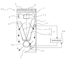
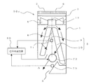
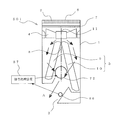
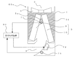
- FIG. 4 is a longitudinal sectional view showing an example of an indoor unit of an air conditioner according to Embodiment 2 of the present invention (hereinafter referred to as an indoor unit 50). Based on FIG. 4, the method of arrangement
- the indoor unit 50 supplies conditioned air to an air-conditioning target area such as a room by using a refrigeration cycle in which a refrigerant is circulated.
- the front-side heat exchanger 9 and the back-side heat exchanger 10 constituting the heat exchanger 5 are longitudinal sections (that is, indoor units) from the front side to the back side of the indoor unit 50.
- the vertical section 50 is viewed from the right side (hereinafter also referred to as the right vertical section), and is divided by the symmetry line 8.
- the symmetry line 8 divides the installation range of the heat exchanger 5 in this cross section in the left-right direction at a substantially central portion. That is, the front-side heat exchanger 9 is arranged on the front side (left side of the drawing) with respect to the symmetry line 8, and the back-side heat exchanger 10 is arranged on the back side (right side of the drawing) with respect to the symmetry line 8.
- the front-side heat exchanger 9 and the rear-side heat exchanger 10 are arranged so that the distance between the front-side heat exchanger 9 and the rear-side heat exchanger 10 is narrower with respect to the air flow direction, that is, the right side longitudinal section. It is arrange
- the front side heat exchanger 9 and the back side heat exchanger 10 are arranged so as to be inclined with respect to the flow direction of the air supplied from the fan 4. Furthermore, the air path area of the back surface side heat exchanger 10 is characterized by being larger than the air path area of the front surface side heat exchanger 9.
- the length in the longitudinal direction of the back side heat exchanger 10 is longer than the length in the longitudinal direction of the front side heat exchanger 9 in the right vertical section. Thereby, the air path area of the back surface side heat exchanger 10 is larger than the air path area of the front surface side heat exchanger 9.
- the other structure (the length of the depth direction in FIG. 4, etc.) of the front side heat exchanger 9 and the back side heat exchanger 10 is the same. That is, the heat transfer area of the back side heat exchanger 10 is larger than the heat transfer area of the front side heat exchanger 9. Further, the rotating shaft 11 of the fan 4 is installed above the symmetry line 8.
- a noise detection microphone 71, a control speaker 72, and a silencing effect detection microphone 73 are provided on the downstream side of the heat exchanger 5. These are connected to the signal processing device 80 as in the first embodiment.
- the noise reduction unit of the indoor unit 50 includes the noise detection microphone 71, the control speaker 72, the noise reduction effect detection microphone 73, and the signal processing device 80.
- the method for controlling the driving sound by the silencer unit is the same as the method described in the first embodiment.
- the indoor unit 50 configured in this manner is an axial / diagonal flow type indoor unit in which the heat exchanger 5 is provided on the downstream side of the fan 4.
- the noise generated from the can be suppressed.
- the indoor unit 50 since the indoor unit 50 includes at least the control speaker 72 and the silencing effect detection microphone 73 among the components of the silencing unit on the downstream side of the heat exchanger 5, it is generated by the fan 4 as in the first embodiment. It is possible to reduce the influence of the turbulence of the airflow on the silencing effect detection microphone 73, and to shorten the path until the control sound emitted from the control speaker 72 reaches the control point (installation position of the silencing effect detection microphone 73). Thus, highly accurate noise control can be performed by the silencer unit.
- the indoor unit 50 according to the second embodiment since the noise detection microphone 71 is also provided on the downstream side of the heat exchanger 5, the turbulence of the air flow generated by the fan 4 is the same as in the first embodiment. The influence on the noise detection microphone 71 and the silencing effect detection microphone 73 can be reduced. For this reason, since the indoor unit 50 according to the second embodiment can increase the coherence between the two microphones as in the first embodiment, a high silencing effect can be obtained.
- the fan 4 can be provided on the upstream side of the heat exchanger 5 and above the casing 1, as in the first embodiment. For this reason, the noise transmission path from the fan 4 can be lengthened, and the distance between the noise detection microphone 71 and the control speaker 72 can be increased. Therefore, the indoor unit 50 according to the second embodiment does not need to increase the speed of the arithmetic processing as in the first embodiment, and thus the cost of the indoor unit 50 can be reduced.
- an amount of air corresponding to the air passage area passes through each of the front-side heat exchanger 9 and the rear-side heat exchanger 10. That is, the air volume of the back surface side heat exchanger 10 is larger than the air volume of the front surface side heat exchanger 9. And when the air which passed each of the front side heat exchanger 9 and the back side heat exchanger 10 merges by this air volume difference, this merged air will bend to the front side (blower outlet 3 side). For this reason, it is no longer necessary to bend the airflow rapidly in the vicinity of the outlet 3, and the pressure loss in the vicinity of the outlet 3 can be reduced. Therefore, the indoor unit 50 according to the second embodiment can further suppress noise compared to the indoor unit 40 according to the first embodiment. Moreover, since the indoor unit 50 can reduce the pressure loss in the blower outlet 3 vicinity, it also becomes possible to reduce power consumption.
- an amount of air corresponding to the heat transfer area passes through each of the front side heat exchanger 9 and the back side heat exchanger 10. For this reason, the heat exchange performance of the heat exchanger 5 is improved.
- the heat exchanger 5 shown in FIG. 4 is comprised by the substantially V shape by the front side heat exchanger 9 and the back side heat exchanger 10 which were formed separately, it is not limited to this structure.
- the front-side heat exchanger 9 and the back-side heat exchanger 10 may be configured as an integrated heat exchanger (see FIG. 5).
- each of the front side heat exchanger 9 and the back side heat exchanger 10 may be configured by a combination of a plurality of heat exchangers (see FIG. 5).
- the front side is the front side heat exchanger 9 and the rear side is the back side heat exchanger 10 with respect to the symmetry line 8.
- the length in the longitudinal direction of the heat exchanger disposed on the back side of the symmetry line 8 may be longer than the length of the heat exchanger disposed on the front side of the symmetry line 8.
- the longitudinal lengths of the plurality of heat exchangers constituting the front-side heat exchanger 9 are each. Is the length of the front heat exchanger 9 in the longitudinal direction.
- the sum of the longitudinal lengths of the plurality of heat exchangers constituting the back side heat exchanger 10 is the longitudinal length of the back side heat exchanger 10.
- the heat exchanger 5 is composed of a plurality of heat exchangers (for example, when the heat exchanger 5 is composed of the front side heat exchanger 9 and the back side heat exchanger 10), the location where the arrangement gradient of the heat exchanger 5 changes ( For example, the heat exchangers do not have to be completely in contact with each other at a substantial connection point between the front-side heat exchanger 9 and the rear-side heat exchanger 10, and there may be some gaps.
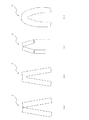
- the shape of the heat exchanger 5 in the right vertical section may be partially or entirely curved (see FIG. 5).
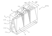
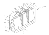
- FIG. 5 is a schematic diagram for explaining a configuration example of the heat exchanger 5.
- FIG. 5 shows the heat exchanger 5 as seen from the right vertical section. Note that the overall shape of the heat exchanger 5 shown in FIG. 5 is substantially ⁇ type, but the overall shape of the heat exchanger is merely an example.
- Fig.5 (a) you may comprise the heat exchanger 5 by a some heat exchanger.
- FIG.5 (b) you may comprise the heat exchanger 5 with an integrated heat exchanger.
- 5 (c) you may comprise the heat exchanger which comprises the heat exchanger 5 by a some heat exchanger further.
- the shape of the heat exchanger 5 may be a curved shape.
- the FIR filter 88 and the LMS algorithm 89 are used for the signal processing device 80.
- any adaptive signal processing circuit that brings the sound detected by the mute effect detection microphone 73 close to zero can be used.
- a filtered-X algorithm generally used in the mute method may be used.
- the signal processing device 80 does not need to be configured to perform adaptive signal processing, and may be configured to generate a control sound using a fixed tap coefficient.
- the signal processing device 80 does not have to be a digital signal processing circuit, but may be an analog signal processing circuit.
- the noise detection microphone 71, the control speaker 72, and the silencing effect detection microphone 73 are provided on the downstream side of the heat exchanger 5, there is a possibility that condensation may occur due to direct contact with cold air. May be used.
- Embodiment 3 FIG.
- the heat exchanger 5 may be configured as follows.
- the difference from the above-described second embodiment will be mainly described, and the same parts as those in the second embodiment are denoted by the same reference numerals.
- the case where the indoor unit is a wall-mounted type attached to the wall surface of the air-conditioning target area is shown as an example.
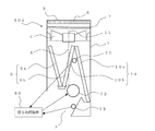
- FIG. 6 is a longitudinal sectional view showing an example of an indoor unit of an air conditioner according to Embodiment 3 of the present invention (hereinafter referred to as an indoor unit 50a). Based on FIG. 6, the method of arrangement
- the indoor unit 50a supplies conditioned air to an air-conditioning target area such as a room by using a refrigeration cycle that circulates refrigerant.
- the arrangement of the heat exchanger 5 is different from the indoor unit 50 of the second embodiment.
- the heat exchanger 5 is composed of three heat exchangers, and each of these heat exchangers is arranged with a different inclination with respect to the flow direction of the air supplied from the fan 4. And the heat exchanger 5 becomes a substantially N type in the right side longitudinal cross-section.
- the heat exchanger 9a and the heat exchanger 9b arranged on the front side of the symmetry line 8 constitute the front side heat exchanger 9
- the heat exchanger 10b constitutes the back side heat exchanger 10.
- the heat exchanger 9b and the heat exchanger 10b are configured as an integrated heat exchanger.
- the symmetry line 8 divides the installation range of the heat exchanger 5 in the right vertical section in the left-right direction at a substantially central portion.
- the length in the longitudinal direction of the back side heat exchanger 10 is longer than the length in the longitudinal direction of the front side heat exchanger 9. That is, the air volume of the back surface side heat exchanger 10 is larger than the air volume of the front surface side heat exchanger 9.
- the comparison of the lengths is the sum of the lengths of the heat exchanger groups constituting the front-side heat exchanger 9 and the sum of the lengths of the heat exchanger groups constituting the rear-side heat exchanger 10. Should be compared.
- a noise detection microphone 71, a control speaker 72, and a silencing effect detection microphone 73 are provided on the downstream side of the heat exchanger 5. These are connected to the signal processing device 80 as in the first embodiment.
- the muffling unit of the indoor unit 50a includes the noise detection microphone 71, the control speaker 72, the muffling effect detection microphone 73, and the signal processing device 80.
- the method for controlling the driving sound by the silencer unit is the same as the method described in the first embodiment.
- the indoor unit 50 a configured as described above is an axial / diagonal flow type indoor unit in which the heat exchanger 5 is provided on the downstream side of the fan 4.
- the noise generated from the can be suppressed.
- the indoor unit 50a since the indoor unit 50a includes at least the control speaker 72 and the silencing effect detection microphone 73 among the components of the silencing unit on the downstream side of the heat exchanger 5, it is generated by the fan 4 as in the first embodiment. It is possible to reduce the influence of the turbulence of the airflow on the silencing effect detection microphone 73, and to shorten the path until the control sound emitted from the control speaker 72 reaches the control point (installation position of the silencing effect detection microphone 73). Thus, highly accurate noise control can be performed by the silencer unit.
- the indoor unit 50a according to the third embodiment since the noise detection microphone 71 is also provided on the downstream side of the heat exchanger 5, the turbulence of the airflow generated by the fan 4 is the same as in the first embodiment. The influence on the noise detection microphone 71 and the silencing effect detection microphone 73 can be reduced. For this reason, since the indoor unit 50a according to the third embodiment can increase the coherence between the two microphones as in the first embodiment, a high silencing effect can be obtained.
- the fan 4 can be provided on the upstream side of the heat exchanger 5 and in the upper part of the casing 1 as in the first embodiment. For this reason, the noise transmission path from the fan 4 can be lengthened, and the distance between the noise detection microphone 71 and the control speaker 72 can be increased. Therefore, similarly to Embodiment 1, the indoor unit 50a according to Embodiment 3 does not need to have a high processing speed, so that the cost of the indoor unit 50a can be reduced.
- the air volume of the rear side heat exchanger 10 is larger than the air volume of the front side heat exchanger 9.
- this merged air is the front side (air outlet 3 To the side).
- the indoor unit 50a according to the third embodiment can further suppress noise compared to the indoor unit 40 according to the first embodiment.
- the indoor unit 50a can reduce the pressure loss in the vicinity of the blower outlet 3, it also becomes possible to reduce power consumption.
- the shape of the heat exchanger 5 is made into a substantially N type in a right side longitudinal cross section, and passes the front side heat exchanger 9 and the back side heat exchanger 10. Since the area can be increased, the wind speed passing through each area can be made smaller than that in the second embodiment. For this reason, the indoor unit 50a which concerns on this Embodiment 3 can reduce the pressure loss in the front side heat exchanger 9 and the back side heat exchanger 10 compared with the indoor unit 50 which concerns on Embodiment 2. FIG. Further, lower power consumption and noise can be achieved.
- the heat exchanger 5 shown in FIG. 6 is comprised by the substantially N type by the three heat exchangers formed separately, it is not limited to this structure.
- each of the three heat exchangers constituting the heat exchanger 5 may be configured by a combination of a plurality of heat exchangers (see FIG. 5).
- the front side is the front side heat exchanger 9 and the rear side is the back side heat exchanger 10 with respect to the symmetry line 8.
- the length in the longitudinal direction of the heat exchanger disposed on the back side of the symmetry line 8 may be longer than the length of the heat exchanger disposed on the front side of the symmetry line 8.
- the longitudinal lengths of the plurality of heat exchangers constituting the front-side heat exchanger 9 are each. Is the length of the front heat exchanger 9 in the longitudinal direction.
- the sum of the longitudinal lengths of the plurality of heat exchangers constituting the back side heat exchanger 10 is the longitudinal length of the back side heat exchanger 10.
- the heat exchanger 5 it is not necessary to incline all the heat exchangers constituting the heat exchanger 5 in the right vertical section, and a part of the heat exchangers constituting the heat exchanger 5 may be arranged vertically in the right vertical section. (See FIG. 5). Further, when the heat exchanger 5 is composed of a plurality of heat exchangers, it is not necessary that the heat exchangers are completely in contact with each other at the location where the arrangement gradient of the heat exchanger 5 is changed, and there are some gaps. May be. Moreover, the shape of the heat exchanger 5 in the right vertical section may be partially or entirely curved (see FIG. 5).
- the FIR filter 88 and the LMS algorithm 89 are used for the signal processing device 80.
- any adaptive signal processing circuit that brings the sound detected by the mute effect detection microphone 73 close to zero may be used.
- a filtered-X algorithm generally used in the mute method may be used.
- the signal processing device 80 does not need to be configured to perform adaptive signal processing, and may be configured to generate a control sound using a fixed tap coefficient.
- the signal processing device 80 does not have to be a digital signal processing circuit, but may be an analog signal processing circuit.
- the noise detection microphone 71, the control speaker 72, and the silencing effect detection microphone 73 are provided on the downstream side of the heat exchanger 5, there is a possibility that condensation may occur due to direct contact with cold air. May be used.
- Embodiment 4 FIG. Moreover, the heat exchanger 5 may be configured as follows. In the fourth embodiment, the difference from the second embodiment and the third embodiment will be mainly described, and the same reference numerals are given to the same parts as the second and third embodiments. ing. Moreover, the case where the indoor unit is a wall-mounted type attached to the wall surface of the air-conditioning target area is shown as an example.
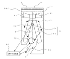
- FIG. 7 is a longitudinal sectional view showing an example of an indoor unit of an air conditioner according to Embodiment 4 of the present invention (hereinafter referred to as an indoor unit 50b). Based on FIG. 7, the method of arrangement
- the indoor unit 50b supplies conditioned air to an air-conditioning target area such as a room by using a refrigeration cycle that circulates refrigerant.
- the arrangement of the heat exchanger 5 is different from the indoor units shown in the second and third embodiments.
- the heat exchanger 5 is composed of four heat exchangers, and each of these heat exchangers is arranged with a different inclination with respect to the flow direction of the air supplied from the fan 4. And the heat exchanger 5 becomes a substantially W type in the right side longitudinal cross-section.
- the heat exchanger 9a and the heat exchanger 9b arranged on the front side of the symmetry line 8 constitute the front side heat exchanger 9
- the heat exchanger 10b constitutes the back side heat exchanger 10.
- the symmetry line 8 divides the installation range of the heat exchanger 5 in the right vertical section in the left-right direction at a substantially central portion.
- the length in the longitudinal direction of the back side heat exchanger 10 is longer than the length in the longitudinal direction of the front side heat exchanger 9. That is, the air volume of the back surface side heat exchanger 10 is larger than the air volume of the front surface side heat exchanger 9.
- the comparison of the lengths is the sum of the lengths of the heat exchanger groups constituting the front-side heat exchanger 9 and the sum of the lengths of the heat exchanger groups constituting the rear-side heat exchanger 10. Should be compared.
- a noise detection microphone 71, a control speaker 72, and a silencing effect detection microphone 73 are provided on the downstream side of the heat exchanger 5. These are connected to the signal processing device 80 as in the first embodiment.
- the muffling unit of the indoor unit 50b includes the noise detection microphone 71, the control speaker 72, the muffling effect detection microphone 73, and the signal processing device 80.
- the method for controlling the driving sound by the silencer unit is the same as the method described in the first embodiment.
- the indoor unit 50b configured as described above is an axial / diagonal flow type indoor unit in which the heat exchanger 5 is provided on the downstream side of the fan 4, and therefore, similarly to the first embodiment, the fan 4 The noise generated from the can be suppressed.
- the indoor unit 50b includes at least the control speaker 72 and the silencing effect detection microphone 73 among the components of the silencing unit on the downstream side of the heat exchanger 5, it is generated by the fan 4 as in the first embodiment. It is possible to reduce the influence of the turbulence of the airflow on the silencing effect detection microphone 73, and to shorten the path until the control sound emitted from the control speaker 72 reaches the control point (installation position of the silencing effect detection microphone 73). Thus, highly accurate noise control can be performed by the silencer unit.
- the indoor unit 50b according to the fourth embodiment since the noise detection microphone 71 is also provided on the downstream side of the heat exchanger 5, the turbulence of the air flow generated by the fan 4 is disturbed as in the first embodiment. The influence on the noise detection microphone 71 and the silencing effect detection microphone 73 can be reduced. For this reason, since the indoor unit 50b according to the fourth embodiment can increase the coherence between the two microphones as in the first embodiment, a high silencing effect can be obtained.
- the fan 4 can be provided on the upstream side of the heat exchanger 5 and in the upper part of the casing 1, as in the first embodiment. For this reason, the noise transmission path from the fan 4 can be lengthened, and the distance between the noise detection microphone 71 and the control speaker 72 can be increased. Therefore, similarly to Embodiment 1, the indoor unit 50b according to Embodiment 4 does not need to have a high processing speed, and thus the cost of the indoor unit 50b can be reduced.
- the air volume of the rear side heat exchanger 10 is larger than the air volume of the front side heat exchanger 9. Therefore, as in the second and third embodiments, when the air that has passed through each of the front-side heat exchanger 9 and the rear-side heat exchanger 10 merges due to the difference in air volume, It will bend to the side (air outlet 3 side). For this reason, it is no longer necessary to bend the airflow rapidly in the vicinity of the outlet 3, and the pressure loss in the vicinity of the outlet 3 can be reduced. Therefore, the indoor unit 50b according to the fourth embodiment can further suppress noise compared to the indoor unit 40 according to the first embodiment. Moreover, since the indoor unit 50b can reduce the pressure loss in the vicinity of the blower outlet 3, it also becomes possible to reduce power consumption.
- the indoor unit 50b which concerns on this Embodiment 4 reduces the pressure loss in the front side heat exchanger 9 and the back side heat exchanger 10 compared with the indoor unit which concerns on Embodiment 2 and Embodiment 3. Thus, further reduction in power consumption and noise can be achieved.
- the heat exchanger 5 shown in FIG. 7 is comprised by the substantially W type
- each of the four heat exchangers constituting the heat exchanger 5 may be configured by a combination of a plurality of heat exchangers (see FIG. 5).
- the front side is the front side heat exchanger 9 and the rear side is the back side heat exchanger 10 with respect to the symmetry line 8.
- the length in the longitudinal direction of the heat exchanger disposed on the back side of the symmetry line 8 may be longer than the length of the heat exchanger disposed on the front side of the symmetry line 8.
- the longitudinal lengths of the plurality of heat exchangers constituting the front-side heat exchanger 9 are each. Is the length of the front heat exchanger 9 in the longitudinal direction.
- the sum of the longitudinal lengths of the plurality of heat exchangers constituting the back side heat exchanger 10 is the longitudinal length of the back side heat exchanger 10.
- the heat exchanger 5 it is not necessary to incline all the heat exchangers constituting the heat exchanger 5 in the right vertical section, and a part of the heat exchangers constituting the heat exchanger 5 may be arranged vertically in the right vertical section. (See FIG. 5). Further, when the heat exchanger 5 is composed of a plurality of heat exchangers, it is not necessary that the heat exchangers are completely in contact with each other at the location where the arrangement gradient of the heat exchanger 5 is changed, and there are some gaps. May be. Moreover, the shape of the heat exchanger 5 in the right vertical section may be partially or entirely curved (see FIG. 5).
- the FIR filter 88 and the LMS algorithm 89 are used for the signal processing device 80.
- any adaptive signal processing circuit that brings the sound detected by the mute effect detection microphone 73 close to zero may be used.
- a filtered-X algorithm generally used in the mute method may be used.
- the signal processing device 80 does not need to be configured to perform adaptive signal processing, and may be configured to generate a control sound using a fixed tap coefficient.
- the signal processing device 80 does not have to be a digital signal processing circuit, but may be an analog signal processing circuit.
- the noise detection microphone 71, the control speaker 72, and the silencing effect detection microphone 73 are provided on the downstream side of the heat exchanger 5, there is a possibility that condensation may occur due to direct contact with cold air. May be used.
- Embodiment 5 FIG. Moreover, the heat exchanger 5 may be configured as follows. In the fifth embodiment, differences from the above-described second to fourth embodiments will be mainly described, and the same parts as those in the second to fourth embodiments are denoted by the same reference numerals. ing. Moreover, the case where the indoor unit is a wall-mounted type attached to the wall surface of the air-conditioning target area is shown as an example.
- FIG. 8 is a longitudinal sectional view showing an example of an indoor unit of an air conditioner according to Embodiment 5 of the present invention (hereinafter referred to as an indoor unit 50c). Based on FIG. 8, the arrangement
- the indoor unit 50c supplies conditioned air to an air-conditioning target area such as a room by using a refrigeration cycle that circulates refrigerant.
- the arrangement of the heat exchanger 5 is different from the indoor units shown in the second to fourth embodiments. More specifically, the indoor unit 50c of the fifth embodiment is configured by two heat exchangers (a front side heat exchanger 9 and a back side heat exchanger 10), as in the second embodiment. However, the arrangement of the front-side heat exchanger 9 and the rear-side heat exchanger 10 is different from the indoor unit 50 shown in the second embodiment.
- the front side heat exchanger 9 and the back side heat exchanger 10 are arranged with different inclinations with respect to the flow direction of the air supplied from the fan 4.
- a front side heat exchanger 9 is disposed on the front side of the symmetry line 8
- a back side heat exchanger 10 is disposed on the back side of the symmetry line 8.
- the heat exchanger 5 has a substantially ⁇ shape in the right vertical section.
- the symmetry line 8 divides the installation range of the heat exchanger 5 in the right vertical section in the left-right direction at a substantially central portion.
- the length in the longitudinal direction of the back side heat exchanger 10 is longer than the length in the longitudinal direction of the front side heat exchanger 9. That is, the air volume of the back surface side heat exchanger 10 is larger than the air volume of the front surface side heat exchanger 9.
- the comparison of the lengths is the sum of the lengths of the heat exchanger groups constituting the front-side heat exchanger 9 and the sum of the lengths of the heat exchanger groups constituting the rear-side heat exchanger 10. Should be compared.
- a noise detection microphone 71, a control speaker 72, and a silencing effect detection microphone 73 are provided on the downstream side of the heat exchanger 5. These are connected to the signal processing device 80 as in the first embodiment.
- the silencer unit of the indoor unit 50c includes the noise detection microphone 71, the control speaker 72, the silence effect detection microphone 73, and the signal processing device 80.
- the method for controlling the driving sound by the silencer unit is the same as the method described in the first embodiment.
- the indoor unit 50c configured as described above has the following internal air flow.
- the indoor air flows into the indoor unit 50 c from the suction port 2 formed in the upper part of the casing 1 by the fan 4.
- dust contained in the air is removed by the filter 7.
- this indoor air passes through the heat exchanger 5 (the front-side heat exchanger 9 and the back-side heat exchanger 10), it is heated or cooled by the refrigerant that is conducted through the heat exchanger 5 to become conditioned air.
- the air passing through the front side heat exchanger 9 flows from the front side to the back side of the indoor unit 50c.
- the air which passes the back side heat exchanger 10 flows from the back side of the indoor unit 50c to the front side.
- the conditioned air that has passed through the heat exchanger 5 (the front-side heat exchanger 9 and the back-side heat exchanger 10) passes from the outlet 3 formed in the lower part of the casing 1 to the outside of the indoor unit 50c, that is, the air-conditioning target area. Blown out.
- the indoor unit 50c configured as described above is an axial / diagonal flow type indoor unit in which the heat exchanger 5 is provided on the downstream side of the fan 4, and therefore, similarly to the first embodiment, the fan 4 The noise generated from the can be suppressed.
- the indoor unit 50c includes at least the control speaker 72 and the silencing effect detection microphone 73 on the downstream side of the heat exchanger 5 among the components of the silencing unit, similar to the first embodiment, the indoor unit 50c is generated by the fan 4. It is possible to reduce the influence of the turbulence of the airflow on the silencing effect detection microphone 73, and to shorten the path until the control sound emitted from the control speaker 72 reaches the control point (installation position of the silencing effect detection microphone 73). Thus, highly accurate noise control can be performed by the silencer unit.
- the indoor unit 50c according to the fifth embodiment since the noise detection microphone 71 is also provided on the downstream side of the heat exchanger 5, the turbulence of the airflow generated in the fan 4 is disturbed as in the first embodiment. The influence on the noise detection microphone 71 and the silencing effect detection microphone 73 can be reduced. For this reason, since the indoor unit 50c according to the fifth embodiment can increase the coherence between the two microphones as in the first embodiment, a high silencing effect can be obtained.
- the fan 4 can be provided on the upstream side of the heat exchanger 5 and in the upper part of the casing 1 as in the first embodiment. For this reason, the noise transmission path from the fan 4 can be lengthened, and the distance between the noise detection microphone 71 and the control speaker 72 can be increased. Therefore, the indoor unit 50c according to the fifth embodiment does not need to increase the speed of the arithmetic processing as in the first embodiment, so that the cost of the indoor unit 50c can be reduced.
- the air volume of the rear side heat exchanger 10 is larger than the air volume of the front side heat exchanger 9. Therefore, as in the second to fourth embodiments, when the air that has passed through each of the front-side heat exchanger 9 and the rear-side heat exchanger 10 joins due to the difference in air volume, It will bend to the side (air outlet 3 side). For this reason, it is no longer necessary to bend the airflow rapidly in the vicinity of the outlet 3, and the pressure loss in the vicinity of the outlet 3 can be reduced. Therefore, the indoor unit 50c according to the fifth embodiment can further suppress noise compared to the indoor unit 40 according to the first embodiment. Moreover, since the indoor unit 50c can reduce the pressure loss in the vicinity of the blower outlet 3, it also becomes possible to reduce power consumption.
- the flow direction of the air flowing out from the back side heat exchanger 10 is the flow from the back side to the front side.
- the indoor unit 50c according to the fifth embodiment can more easily bend the air flow after passing through the heat exchanger 5. That is, the indoor unit 50c according to the fifth embodiment can more easily control the airflow of the air blown out from the outlet 3 than the indoor unit 50 according to the second embodiment. Therefore, compared to the indoor unit 50 according to the second embodiment, the indoor unit 50c according to the fifth embodiment further eliminates the need to bend the airflow in the vicinity of the air outlet 3, and further reduces power consumption and noise. Is possible.
- the heat exchanger 5 shown in FIG. 8 is configured in a substantially ⁇ shape by the front side heat exchanger 9 and the back side heat exchanger 10 formed separately, but is not limited to this configuration.
- the front-side heat exchanger 9 and the back-side heat exchanger 10 may be configured as an integrated heat exchanger (see FIG. 5).
- each of the front side heat exchanger 9 and the back side heat exchanger 10 may be configured by a combination of a plurality of heat exchangers (see FIG. 5).
- the front side is the front side heat exchanger 9 and the rear side is the back side heat exchanger 10 with respect to the symmetry line 8.
- the length in the longitudinal direction of the heat exchanger disposed on the back side of the symmetry line 8 may be longer than the length of the heat exchanger disposed on the front side of the symmetry line 8.
- the longitudinal lengths of the plurality of heat exchangers constituting the front-side heat exchanger 9 are each. Is the length of the front heat exchanger 9 in the longitudinal direction.
- the sum of the longitudinal lengths of the plurality of heat exchangers constituting the back side heat exchanger 10 is the longitudinal length of the back side heat exchanger 10.
- the heat exchanger 5 it is not necessary to incline all the heat exchangers constituting the heat exchanger 5 in the right vertical section, and a part of the heat exchangers constituting the heat exchanger 5 may be arranged vertically in the right vertical section. (See FIG. 5). Further, when the heat exchanger 5 is composed of a plurality of heat exchangers, it is not necessary that the heat exchangers are completely in contact with each other at the location where the arrangement gradient of the heat exchanger 5 is changed, and there are some gaps. May be. Moreover, the shape of the heat exchanger 5 in the right vertical section may be partially or entirely curved (see FIG. 5).
- the FIR filter 88 and the LMS algorithm 89 are used for the signal processing device 80.
- any adaptive signal processing circuit that brings the sound detected by the mute effect detection microphone 73 close to zero may be used.
- a filtered-X algorithm generally used in the mute method may be used.
- the signal processing device 80 does not need to be configured to perform adaptive signal processing, and may be configured to generate a control sound using a fixed tap coefficient.
- the signal processing device 80 does not have to be a digital signal processing circuit, but may be an analog signal processing circuit.
- the noise detection microphone 71, the control speaker 72, and the silencing effect detection microphone 73 are provided on the downstream side of the heat exchanger 5, there is a possibility that condensation may occur due to direct contact with cold air. May be used.
- Embodiment 6 FIG. Moreover, the heat exchanger 5 may be configured as follows. In the sixth embodiment, differences from the above-described second to fifth embodiments will be mainly described, and the same parts as those in the second to fifth embodiments are denoted by the same reference numerals. Yes. Moreover, the case where the indoor unit is a wall-mounted type attached to the wall surface of the air-conditioning target area is shown as an example.
- FIG. 9 is a longitudinal sectional view showing an example of an indoor unit of an air conditioner according to Embodiment 6 of the present invention (hereinafter referred to as an indoor unit 50d). Based on FIG. 9, the arrangement
- the indoor unit 50d supplies conditioned air to an air-conditioning target area such as a room by using a refrigeration cycle that circulates refrigerant.
- the arrangement of the heat exchanger 5 is different from the indoor units shown in the second to fifth embodiments. More specifically, the indoor unit 50d of the sixth embodiment is composed of three heat exchangers as in the third embodiment. However, the arrangement of these three heat exchangers is different from the indoor unit 50a shown in the third embodiment.
- each of the three heat exchangers constituting the heat exchanger 5 is arranged with a different inclination with respect to the flow direction of the air supplied from the fan 4.
- the heat exchanger 5 has a substantially ⁇ type in the right vertical section.
- the heat exchanger 9a and the heat exchanger 9b arranged on the front side of the symmetry line 8 constitute the front side heat exchanger 9
- the heat exchanger 10b constitutes the back side heat exchanger 10. That is, in the sixth embodiment, the heat exchanger 9b and the heat exchanger 10b are configured as an integrated heat exchanger.
- the symmetry line 8 divides the installation range of the heat exchanger 5 in the right vertical section in the left-right direction at a substantially central portion.
- the length in the longitudinal direction of the back side heat exchanger 10 is longer than the length in the longitudinal direction of the front side heat exchanger 9. That is, the air volume of the back surface side heat exchanger 10 is larger than the air volume of the front surface side heat exchanger 9.
- the comparison of the lengths is the sum of the lengths of the heat exchanger groups constituting the front-side heat exchanger 9 and the sum of the lengths of the heat exchanger groups constituting the rear-side heat exchanger 10. Should be compared.
- a noise detection microphone 71, a control speaker 72, and a silencing effect detection microphone 73 are provided on the downstream side of the heat exchanger 5. These are connected to the signal processing device 80 as in the first embodiment.
- the silencer unit of the indoor unit 50d includes the noise detection microphone 71, the control speaker 72, the silence effect detection microphone 73, and the signal processing device 80.
- the method for controlling the driving sound by the silencer unit is the same as the method described in the first embodiment.
- the indoor unit 50d configured as described above is an axial / diagonal flow type indoor unit in which the heat exchanger 5 is provided on the downstream side of the fan 4, and therefore, similarly to the first embodiment, the fan 4 The noise generated from the can be suppressed.
- the indoor unit 50d includes at least the control speaker 72 and the silencing effect detection microphone 73 among the components of the silencing unit on the downstream side of the heat exchanger 5, similar to the first embodiment, the indoor unit 50d is generated by the fan 4. It is possible to reduce the influence of the turbulence of the airflow on the silencing effect detection microphone 73, and to shorten the path until the control sound emitted from the control speaker 72 reaches the control point (installation position of the silencing effect detection microphone 73). Thus, highly accurate noise control can be performed by the silencer unit.
- the indoor unit 50d according to the sixth embodiment since the noise detection microphone 71 is also provided on the downstream side of the heat exchanger 5, the turbulence of the airflow generated by the fan 4 is similar to the first embodiment. The influence on the noise detection microphone 71 and the silencing effect detection microphone 73 can be reduced. For this reason, since the indoor unit 50d according to the sixth embodiment can increase the coherence between the two microphones as in the first embodiment, a high silencing effect can be obtained.
- the fan 4 can be provided on the upstream side of the heat exchanger 5 and in the upper part of the casing 1 as in the first embodiment. For this reason, the noise transmission path from the fan 4 can be lengthened, and the distance between the noise detection microphone 71 and the control speaker 72 can be increased. Therefore, the indoor unit 50d according to the sixth embodiment does not need to increase the speed of the arithmetic processing as in the first embodiment, and thus the cost of the indoor unit 50d can be reduced.
- the air volume of the rear side heat exchanger 10 is larger than the air volume of the front side heat exchanger 9. Therefore, as in the second to fifth embodiments, when the air that has passed through each of the front-side heat exchanger 9 and the rear-side heat exchanger 10 joins due to the difference in air volume, It will bend to the side (air outlet 3 side). For this reason, it is no longer necessary to bend the airflow rapidly in the vicinity of the outlet 3, and the pressure loss in the vicinity of the outlet 3 can be reduced. Therefore, the indoor unit 50d according to the sixth embodiment can further suppress noise compared to the indoor unit 40 according to the first embodiment. Moreover, since the indoor unit 50d can reduce the pressure loss in the vicinity of the blower outlet 3, the power consumption can also be reduced.
- the flow direction of the air flowing out from the back side heat exchanger 10 is the flow from the back side to the front side.
- the indoor unit 50d according to the sixth embodiment can bend the air flow after passing through the heat exchanger 5 more easily. That is, the indoor unit 50d according to the sixth embodiment can more easily control the airflow of the air blown from the outlet 3 than the indoor unit 50a according to the third embodiment. Therefore, the indoor unit 50d according to the sixth embodiment does not need to bend the airflow in the vicinity of the air outlet 3 more rapidly than the indoor unit 50a according to the third embodiment, thereby further reducing power consumption and noise. Is possible.
- the area passing through the front side heat exchanger 9 and the back side heat exchanger 10 can be increased, so that each passes through.
- the wind speed can be made smaller than that in the fifth embodiment. For this reason, compared with Embodiment 5, the pressure loss in the front side heat exchanger 9 and the back side heat exchanger 10 can be reduced, and further reduction in power consumption and noise can be achieved.
- the heat exchanger 5 shown in FIG. 9 is comprised by the substantially ⁇ type
- each of the three heat exchangers constituting the heat exchanger 5 may be configured by a combination of a plurality of heat exchangers (see FIG. 5).
- the front side is the front side heat exchanger 9 and the rear side is the back side heat exchanger 10 with respect to the symmetry line 8.
- the length in the longitudinal direction of the heat exchanger disposed on the back side of the symmetry line 8 may be longer than the length of the heat exchanger disposed on the front side of the symmetry line 8.
- the longitudinal lengths of the plurality of heat exchangers constituting the front-side heat exchanger 9 are each. Is the length of the front heat exchanger 9 in the longitudinal direction.
- the sum of the longitudinal lengths of the plurality of heat exchangers constituting the back side heat exchanger 10 is the longitudinal length of the back side heat exchanger 10.
- the heat exchanger 5 it is not necessary to incline all the heat exchangers constituting the heat exchanger 5 in the right vertical section, and a part of the heat exchangers constituting the heat exchanger 5 may be arranged vertically in the right vertical section. (See FIG. 5). Further, when the heat exchanger 5 is composed of a plurality of heat exchangers, it is not necessary that the heat exchangers are completely in contact with each other at the location where the arrangement gradient of the heat exchanger 5 is changed, and there are some gaps. May be. Moreover, the shape of the heat exchanger 5 in the right vertical section may be partially or entirely curved (see FIG. 5).
- the FIR filter 88 and the LMS algorithm 89 are used for the signal processing device 80.
- any adaptive signal processing circuit that brings the sound detected by the mute effect detection microphone 73 close to zero can be used.
- a filtered-X algorithm generally used in the mute method may be used.
- the signal processing device 80 does not need to be configured to perform adaptive signal processing, and may be configured to generate a control sound using a fixed tap coefficient.
- the signal processing device 80 does not have to be a digital signal processing circuit, but may be an analog signal processing circuit.
- the noise detection microphone 71, the control speaker 72, and the silencing effect detection microphone 73 are provided on the downstream side of the heat exchanger 5, there is a possibility that condensation may occur due to direct contact with cold air. May be used.
- Embodiment 7 FIG. Moreover, the heat exchanger 5 may be configured as follows. In the seventh embodiment, the difference from the above-described second to sixth embodiments will be mainly described, and the same parts as those in the second to sixth embodiments are denoted by the same reference numerals. Yes. Moreover, the case where the indoor unit is a wall-mounted type attached to the wall surface of the air-conditioning target area is shown as an example.
- FIG. 10 is a longitudinal sectional view showing an example of an indoor unit of an air conditioner according to Embodiment 7 of the present invention (hereinafter referred to as an indoor unit 50e). Based on FIG. 10, the method of arrangement
- the indoor unit 50e supplies conditioned air to an air-conditioning target area such as a room by using a refrigeration cycle that circulates refrigerant.
- the arrangement of the heat exchanger 5 is different from the indoor units shown in the second to sixth embodiments. More specifically, the indoor unit 50e according to the seventh embodiment includes four heat exchangers as in the fourth embodiment. However, the arrangement of these four heat exchangers is different from the indoor unit 50b shown in the fourth embodiment.
- each of the four heat exchangers constituting the heat exchanger 5 is arranged with a different inclination with respect to the flow direction of the air supplied from the fan 4.
- the heat exchanger 5 has a substantially M shape in the right vertical section.
- the heat exchanger 9a and the heat exchanger 9b arranged on the front side of the symmetry line 8 constitute the front side heat exchanger 9
- the heat exchanger 10b constitutes the back side heat exchanger 10.
- the symmetry line 8 divides the installation range of the heat exchanger 5 in the right vertical section in the left-right direction at a substantially central portion.
- the length in the longitudinal direction of the back side heat exchanger 10 is longer than the length in the longitudinal direction of the front side heat exchanger 9. That is, the air volume of the back surface side heat exchanger 10 is larger than the air volume of the front surface side heat exchanger 9.
- the comparison of the lengths is the sum of the lengths of the heat exchanger groups constituting the front-side heat exchanger 9 and the sum of the lengths of the heat exchanger groups constituting the rear-side heat exchanger 10. Should be compared.
- a noise detection microphone 71, a control speaker 72, and a silencing effect detection microphone 73 are provided on the downstream side of the heat exchanger 5. These are connected to the signal processing device 80 as in the first embodiment.
- the muffling unit of the indoor unit 50e includes the noise detection microphone 71, the control speaker 72, the muffling effect detection microphone 73, and the signal processing device 80.
- the method for controlling the driving sound by the silencer unit is the same as the method described in the first embodiment.
- the indoor unit 50e configured as described above is an axial / diagonal flow type indoor unit in which the heat exchanger 5 is provided on the downstream side of the fan 4, and therefore, similarly to the first embodiment, the fan 4 The noise generated from the can be suppressed.
- the indoor unit 50e since the indoor unit 50e includes at least the control speaker 72 and the silencing effect detection microphone 73 among the components of the silencing unit on the downstream side of the heat exchanger 5, similar to the first embodiment, the indoor unit 50e is generated by the fan 4. It is possible to reduce the influence of the turbulence of the airflow on the silencing effect detection microphone 73, and to shorten the path until the control sound emitted from the control speaker 72 reaches the control point (installation position of the silencing effect detection microphone 73). Thus, highly accurate noise control can be performed by the silencer unit.
- the indoor unit 50e according to the seventh embodiment since the noise detection microphone 71 is also provided on the downstream side of the heat exchanger 5, the turbulence of the air flow generated by the fan 4 is disturbed as in the first embodiment. The influence on the noise detection microphone 71 and the silencing effect detection microphone 73 can be reduced. For this reason, since the indoor unit 50e according to the seventh embodiment can increase the coherence between the two microphones as in the first embodiment, a high silencing effect can be obtained.
- the fan 4 can be provided on the upstream side of the heat exchanger 5 and in the upper part of the casing 1 as in the first embodiment. For this reason, the noise transmission path from the fan 4 can be lengthened, and the distance between the noise detection microphone 71 and the control speaker 72 can be increased. Therefore, the indoor unit 50e according to the seventh embodiment does not need to increase the speed of the arithmetic processing as in the first embodiment, and thus the cost of the indoor unit 50e can be reduced.
- the air volume of the rear side heat exchanger 10 is larger than the air volume of the front side heat exchanger 9. Therefore, as in Embodiments 2 to 6, when the air that has passed through each of the front-side heat exchanger 9 and the rear-side heat exchanger 10 joins due to the difference in air volume, It will bend to the side (air outlet 3 side). For this reason, it is no longer necessary to bend the airflow rapidly in the vicinity of the outlet 3, and the pressure loss in the vicinity of the outlet 3 can be reduced. Therefore, the indoor unit 50e according to the seventh embodiment can further suppress noise compared to the indoor unit 40 according to the first embodiment. Moreover, since the indoor unit 50e can reduce the pressure loss in the vicinity of the blower outlet 3, it also becomes possible to reduce power consumption.
- the indoor unit 50e according to the seventh embodiment the flow direction of the air flowing out from the back side heat exchanger 10 is the flow from the back side to the front side. For this reason, the indoor unit 50e which concerns on this Embodiment 7 becomes easier to bend the flow of the air after passing the heat exchanger 5.
- FIG. That is, the indoor unit 50e according to the seventh embodiment can more easily control the airflow of the air blown from the outlet 3 than the indoor unit 50b according to the fourth embodiment. Therefore, in the indoor unit 50e according to the seventh embodiment, compared with the indoor unit 50b according to the fourth embodiment, it is no longer necessary to bend the airflow in the vicinity of the air outlet 3 and further reduce power consumption and noise. Is possible.
- the area which passes the front side heat exchanger 9 and the back side heat exchanger 10 can be taken large by making the shape of the heat exchanger 5 into a substantially M type in the right-side vertical cross section, it passes each. It becomes possible to make a wind speed smaller than Embodiment 5 and Embodiment 6. FIG. For this reason, compared with Embodiment 5 and Embodiment 6, the pressure loss in the front side heat exchanger 9 and the back side heat exchanger 10 can be reduced, and further reduction in power consumption and noise is possible. It becomes.
- the heat exchanger 5 shown in FIG. 10 is comprised by the substantially M type
- each of the four heat exchangers constituting the heat exchanger 5 may be configured by a combination of a plurality of heat exchangers (see FIG. 5).
- the front side is the front side heat exchanger 9 and the rear side is the back side heat exchanger 10 with respect to the symmetry line 8.
- the length in the longitudinal direction of the heat exchanger disposed on the back side of the symmetry line 8 may be longer than the length of the heat exchanger disposed on the front side of the symmetry line 8.
- the longitudinal lengths of the plurality of heat exchangers constituting the front-side heat exchanger 9 are each. Is the length of the front heat exchanger 9 in the longitudinal direction.
- the sum of the longitudinal lengths of the plurality of heat exchangers constituting the back side heat exchanger 10 is the longitudinal length of the back side heat exchanger 10.
- the heat exchanger 5 it is not necessary to incline all the heat exchangers constituting the heat exchanger 5 in the right vertical section, and a part of the heat exchangers constituting the heat exchanger 5 may be arranged vertically in the right vertical section. (See FIG. 5). Further, when the heat exchanger 5 is composed of a plurality of heat exchangers, it is not necessary that the heat exchangers are completely in contact with each other at the location where the arrangement gradient of the heat exchanger 5 is changed, and there are some gaps. May be. Moreover, the shape of the heat exchanger 5 in the right vertical section may be partially or entirely curved (see FIG. 5).
- the FIR filter 88 and the LMS algorithm 89 are used for the signal processing device 80.
- any adaptive signal processing circuit that brings the sound detected by the mute effect detection microphone 73 close to zero can be used.
- a filtered-X algorithm generally used in the mute method may be used.
- the signal processing device 80 does not need to be configured to perform adaptive signal processing, and may be configured to generate a control sound using a fixed tap coefficient.
- the signal processing device 80 does not have to be a digital signal processing circuit, but may be an analog signal processing circuit.
- the noise detection microphone 71, the control speaker 72, and the silencing effect detection microphone 73 are provided on the downstream side of the heat exchanger 5, there is a possibility that condensation may occur due to direct contact with cold air. May be used.
- Embodiment 8 FIG. Moreover, the heat exchanger 5 may be configured as follows.
- the difference from the above-described second to seventh embodiments will be mainly described, and the same parts as those in the second to seventh embodiments are denoted by the same reference numerals. Yes.
- the case where the indoor unit is a wall-mounted type attached to the wall surface of the air-conditioning target area is shown as an example.
- FIG. 11 is a longitudinal sectional view showing an example of an indoor unit of an air conditioner according to Embodiment 8 of the present invention (hereinafter referred to as an indoor unit 50f). Based on FIG. 11, the method of arrangement
- the indoor unit 50f supplies conditioned air to an air-conditioning target area such as a room by using a refrigeration cycle in which a refrigerant is circulated.
- the arrangement of the heat exchanger 5 is different from the indoor units shown in the second to seventh embodiments. More specifically, the indoor unit 50f of the eighth embodiment is composed of two heat exchangers (a front-side heat exchanger 9 and a rear-side heat exchanger 10), as in the fifth embodiment, and has a right vertical cross section. In FIG. However, in Embodiment 8, the pressure loss of the front side heat exchanger 9 and the pressure loss of the back side heat exchanger 10 are made different from each other, whereby the air volume of the front side heat exchanger 9 and the back side heat exchange are changed. The air volume of the vessel 10 is different.
- the front side heat exchanger 9 and the back side heat exchanger 10 are arranged with different inclinations with respect to the flow direction of the air supplied from the fan 4.
- a front side heat exchanger 9 is arranged on the front side of the symmetry line 8
- a back side heat exchanger 10 is arranged on the back side of the symmetry line 8.
- the heat exchanger 5 has a substantially ⁇ shape in the right vertical section.
- the length in the longitudinal direction of the rear side heat exchanger 10 and the length in the longitudinal direction of the front side heat exchanger 9 are the same. And the specifications of the front side heat exchanger 9 and the back side heat exchanger 10 are determined so that the pressure loss of the back side heat exchanger 10 becomes smaller than the pressure loss of the front side heat exchanger 9.
- the length in the short side direction (fin width) of the back side heat exchanger 10 in the right vertical section is set to the right side. It is good to make it smaller than the length (width of a fin) of the transversal direction of the front side heat exchanger 9 in a longitudinal section.
- the distance between the fins of the back surface side heat exchanger 10 may be larger than the distance between the fins of the front surface side heat exchanger 9.
- the pipe diameter of the back side heat exchanger 10 may be smaller than the pipe diameter of the front side heat exchanger 9.
- the number of pipes of the back surface side heat exchanger 10 may be smaller than the number of pipes of the front surface side heat exchanger 9.
- the symmetry line 8 divides the installation range of the heat exchanger 5 in the right vertical section in the left-right direction at a substantially central portion.
- a noise detection microphone 71, a control speaker 72, and a silencing effect detection microphone 73 are provided on the downstream side of the heat exchanger 5. These are connected to the signal processing device 80 as in the first embodiment.
- the silencing unit of the indoor unit 50f includes the noise detecting microphone 71, the control speaker 72, the silencing effect detecting microphone 73, and the signal processing device 80.
- the method for controlling the driving sound by the silencer unit is the same as the method described in the first embodiment.
- the indoor unit 50f configured as described above is an axial / diagonal flow type indoor unit in which the heat exchanger 5 is provided on the downstream side of the fan 4, and therefore, similarly to the first embodiment, the fan 4 The noise generated from the can be suppressed.
- the indoor unit 50f includes at least the control speaker 72 and the silencing effect detection microphone 73 among the components of the silencing unit on the downstream side of the heat exchanger 5, similar to the first embodiment, the indoor unit 50f is generated by the fan 4. It is possible to reduce the influence of the turbulence of the airflow on the silencing effect detection microphone 73, and to shorten the path until the control sound emitted from the control speaker 72 reaches the control point (installation position of the silencing effect detection microphone 73). Thus, highly accurate noise control can be performed by the silencer unit.
- the indoor unit 50f according to the eighth embodiment since the noise detection microphone 71 is also provided on the downstream side of the heat exchanger 5, the turbulence of the air flow generated by the fan 4 is disturbed as in the first embodiment. The influence on the noise detection microphone 71 and the silencing effect detection microphone 73 can be reduced. For this reason, since the indoor unit 50f according to the eighth embodiment can increase the coherence between the two microphones as in the first embodiment, a high silencing effect can be obtained.
- the fan 4 can be provided on the upstream side of the heat exchanger 5 and above the casing 1 as in the first embodiment. For this reason, the noise transmission path from the fan 4 can be lengthened, and the distance between the noise detection microphone 71 and the control speaker 72 can be increased. Therefore, the indoor unit 50f according to the eighth embodiment does not need to increase the speed of the arithmetic processing as in the first embodiment, so that the cost of the indoor unit 50f can be reduced.
- an amount of air corresponding to the pressure loss passes through each of the front-side heat exchanger 9 and the rear-side heat exchanger 10. That is, the air volume of the back surface side heat exchanger 10 is larger than the air volume of the front surface side heat exchanger 9. And when the air which passed each of the front side heat exchanger 9 and the back side heat exchanger 10 merges by this air volume difference, this merged air will bend to the front side (blower outlet 3 side). For this reason, it is no longer necessary to bend the airflow rapidly in the vicinity of the outlet 3, and the pressure loss in the vicinity of the outlet 3 can be reduced.
- the indoor unit 50f according to the eighth embodiment suppresses noise further than the indoor unit 40 according to the first embodiment without increasing the length of the rear side heat exchanger 10 in the right vertical section. Is possible. Moreover, since the indoor unit 50f can reduce the pressure loss in the vicinity of the blower outlet 3, the power consumption can also be reduced.
- the heat exchanger 5 shown in FIG. 11 is comprised by the substantially (LAMBDA) type
- the shape of the heat exchanger 5 in the right vertical section may be configured to be approximately V-shaped, approximately N-shaped, approximately W-shaped, approximately ⁇ -shaped or approximately M-shaped.
- each of the front side heat exchanger 9 and the back side heat exchanger 10 may be configured by a combination of a plurality of heat exchangers (see FIG. 5).
- the front side is the front side heat exchanger 9 and the rear side is the back side heat exchanger 10 with respect to the symmetry line 8. That is, the pressure loss of the heat exchanger arranged on the back side of the symmetry line 8 may be made smaller than the pressure loss of the heat exchanger arranged on the front side of the symmetry line 8.
- the sum of the pressure loss of each of the plurality of heat exchangers constituting the back side heat exchanger 10 becomes the pressure loss of the back side heat exchanger 10.
- the heat exchanger 5 is composed of a plurality of heat exchangers (for example, when the heat exchanger 5 is composed of the front side heat exchanger 9 and the back side heat exchanger 10), the location where the arrangement gradient of the heat exchanger 5 changes ( For example, the heat exchangers do not have to be completely in contact with each other at a substantial connection point between the front-side heat exchanger 9 and the rear-side heat exchanger 10, and there may be some gaps.
- the shape of the heat exchanger 5 in the right vertical section may be partially or entirely curved (see FIG. 5).
- the FIR filter 88 and the LMS algorithm 89 are used for the signal processing device 80.
- any adaptive signal processing circuit that brings the sound detected by the mute effect detection microphone 73 close to zero can be used.
- a filtered-X algorithm generally used in the mute method may be used.
- the signal processing device 80 does not need to be configured to perform adaptive signal processing, and may be configured to generate a control sound using a fixed tap coefficient.
- the signal processing device 80 does not have to be a digital signal processing circuit, but may be an analog signal processing circuit.
- the noise detection microphone 71, the control speaker 72, and the silencing effect detection microphone 73 are provided on the downstream side of the heat exchanger 5, there is a possibility that condensation may occur due to direct contact with cold air. May be used.
- Embodiment 9 FIG. Further, in Embodiments 2 to 8 described above, fan 4 may be arranged as follows. In the ninth embodiment, differences from the above-described second to eighth embodiments will be mainly described, and the same parts as those in the second to eighth embodiments are denoted by the same reference numerals. Yes. Moreover, the case where the indoor unit is a wall-mounted type attached to the wall surface of the air-conditioning target area is shown as an example.
- FIG. 12 is a longitudinal sectional view showing an example of an indoor unit of an air conditioner according to Embodiment 9 of the present invention (hereinafter referred to as an indoor unit 50g). Based on FIGS. 12 (a) to 12 (c), the arrangement of the fans 4 in the indoor unit 50g will be described.
- the indoor unit 50g supplies conditioned air to an air-conditioning target area such as a room by using a refrigeration cycle that circulates refrigerant.
- the heat exchanger 5 of the indoor unit 50g according to the ninth embodiment has the same arrangement as the indoor unit 50c of the fifth embodiment.
- the indoor unit 50g according to the ninth embodiment is different from the indoor unit 50c according to the fifth embodiment in the manner in which the fan 4 is arranged. That is, in the indoor unit 50g according to the ninth embodiment, the arrangement position of the fan 4 is determined according to the air volume and the heat transfer area of the front side heat exchanger 9 and the back side heat exchanger 10.
- the muffling unit of the indoor unit 50g includes the noise detection microphone 71, the control speaker 72, the muffling effect detection microphone 73, and the signal processing device 80.
- the method for controlling the driving sound by the silencer unit is the same as the method described in the first embodiment.
- the heat transfer area is larger than that of the front heat exchanger 9.
- the air volume of the large rear side heat exchanger 10 may be insufficient.
- the heat exchanger 5 (the front surface side heat exchanger 9 and the back surface side heat exchanger 10) may not be able to exhibit desired heat exchange performance.
- the arrangement position of the fan 4 may be moved in the back direction.
- the air volume of the back side heat exchanger 10 may be insufficient, such as when the pressure loss of the back side heat exchanger 10 is large.
- the air volume adjustment by the configuration of the front side heat exchanger 9 and the back side heat exchanger 10 passed through the front side heat exchanger 9 and the back side heat exchanger 10.
- the air that has joined later cannot be adjusted to a desired angle.
- the air merged after passing through each of the front surface side heat exchanger 9 and the back surface side heat exchanger 10 may not bend more than a desired angle.
- the arrangement position of the fan 4 may be moved in the back direction.
- the heat transfer area of the front side heat exchanger 9 may be larger than the heat transfer area of the back side heat exchanger 10.
- the arrangement position of the fan 4 may be moved in the front direction.
- the air volume of the front-side heat exchanger 9 may become larger than necessary.
- the air volume adjustment by the configuration of the front side heat exchanger 9 and the back side heat exchanger 10 passed through the front side heat exchanger 9 and the back side heat exchanger 10.
- the air which joined after passing each of the front side heat exchanger 9 and the back side heat exchanger 10 may bend more than a desired angle. In such a case, the arrangement position of the fan 4 may be moved in the front direction as shown in FIG.
- the indoor unit 50g according to the ninth embodiment is an axial / diagonal flow type indoor unit in which the heat exchanger 5 is provided on the downstream side of the fan 4, the fan 50g is similar to the first embodiment.
- the noise generated from 4 can be suppressed.
- the indoor unit 50g includes at least the control speaker 72 and the silencing effect detection microphone 73 among the components of the silencing unit on the downstream side of the heat exchanger 5, and thus is generated by the fan 4 as in the first embodiment. It is possible to reduce the influence of the turbulence of the airflow on the silencing effect detection microphone 73, and to shorten the path until the control sound emitted from the control speaker 72 reaches the control point (installation position of the silencing effect detection microphone 73). Thus, highly accurate noise control can be performed by the silencer unit.
- the indoor unit 50g according to the ninth embodiment since the noise detection microphone 71 is also provided on the downstream side of the heat exchanger 5, the turbulence of the airflow generated by the fan 4 is similar to the first embodiment. The influence on the noise detection microphone 71 and the silencing effect detection microphone 73 can be reduced. For this reason, since the indoor unit 50g according to the ninth embodiment can increase the coherence between the two microphones as in the first embodiment, a high silencing effect can be obtained.
- the fan 4 can be provided on the upstream side of the heat exchanger 5 and above the casing 1 as in the first embodiment. For this reason, the noise transmission path from the fan 4 can be lengthened, and the distance between the noise detection microphone 71 and the control speaker 72 can be increased. Therefore, the indoor unit 50g according to the ninth embodiment does not need to increase the speed of the arithmetic processing as in the first embodiment, and thus the cost of the indoor unit 50g can be reduced.
- the heat exchanger 5 shown in FIG. 12 is comprised by the substantially (LAMBDA) type
- the shape of the heat exchanger 5 in the right vertical section may be configured to be approximately V-shaped, approximately N-shaped, approximately W-shaped, approximately ⁇ -shaped, approximately M-shaped, or the like.
- each of the front side heat exchanger 9 and the back side heat exchanger 10 may be configured by a combination of a plurality of heat exchangers (see FIG. 5).
- the front side is the front side heat exchanger 9 and the rear side is the back side heat exchanger 10 with respect to the symmetry line 8.
- the longitudinal lengths of the plurality of heat exchangers constituting the front-side heat exchanger 9 are each.
- the sum of (or pressure loss) is the longitudinal length (or pressure loss) of the front-side heat exchanger 9.
- the sum of the longitudinal lengths (or pressure losses) of the plurality of heat exchangers constituting the back side heat exchanger 10 is the longitudinal direction length (or pressure loss) of the back side heat exchanger 10.
- the heat exchanger 5 is composed of a plurality of heat exchangers (for example, when the heat exchanger 5 is composed of the front side heat exchanger 9 and the back side heat exchanger 10), the location where the arrangement gradient of the heat exchanger 5 changes ( For example, the heat exchangers do not have to be completely in contact with each other at a substantial connection point between the front-side heat exchanger 9 and the rear-side heat exchanger 10, and there may be some gaps.
- the shape of the heat exchanger 5 in the right vertical section may be partially or entirely curved (see FIG. 5).
- the FIR filter 88 and the LMS algorithm 89 are used for the signal processing device 80.
- any adaptive signal processing circuit that brings the sound detected by the mute effect detection microphone 73 close to zero can be used.
- a filtered-X algorithm generally used in the mute method may be used.
- the signal processing device 80 does not need to be configured to perform adaptive signal processing, and may be configured to generate a control sound using a fixed tap coefficient.
- the signal processing device 80 does not have to be a digital signal processing circuit, but may be an analog signal processing circuit.
- the noise detection microphone 71, the control speaker 72, and the silencing effect detection microphone 73 are provided on the downstream side of the heat exchanger 5, there is a possibility that condensation may occur due to direct contact with cold air. May be used.
- Embodiment 10 FIG. Further, in the second to ninth embodiments described above, the fan 4 may be arranged as follows. In the tenth embodiment, differences from the above-described second to ninth embodiments will be mainly described, and the same parts as those in the second to ninth embodiments are denoted by the same reference numerals. Yes. Moreover, the case where the indoor unit is a wall-mounted type attached to the wall surface of the air-conditioning target area is shown as an example.
- FIG. 13 is a longitudinal sectional view showing an example of an indoor unit of an air conditioner according to Embodiment 10 of the present invention (hereinafter referred to as an indoor unit 50h). Based on FIG. 13, the arrangement
- the indoor unit 50h supplies conditioned air to an air-conditioning target area such as a room by using a refrigeration cycle in which a refrigerant is circulated.
- the heat exchanger 5 of the indoor unit 50h according to the tenth embodiment has the same arrangement as the indoor unit 50c of the fifth embodiment. However, the indoor unit 50h according to the tenth embodiment is different from the indoor unit 50c according to the fifth embodiment in the manner in which the fan 4 is arranged. That is, in the indoor unit 50h according to the tenth embodiment, the inclination of the fan 4 is determined according to the air volume and the heat transfer area of the front side heat exchanger 9 and the back side heat exchanger 10.
- a noise detection microphone 71, a control speaker 72, and a silencing effect detection microphone 73 are provided on the downstream side of the heat exchanger 5. These are connected to the signal processing device 80 as in the first embodiment.
- the muffling unit of the indoor unit 50h includes the noise detection microphone 71, the control speaker 72, the muffling effect detection microphone 73, and the signal processing device 80.
- the method for controlling the driving sound by the silencer unit is the same as the method described in the first embodiment.
- the air volume of the back side heat exchanger 10 having a larger heat transfer area than the front side heat exchanger 9 may be insufficient.
- the fan 4 cannot be moved in the front-rear direction to adjust the air volume.
- the heat exchanger 5 (the front surface side heat exchanger 9 and the back surface side heat exchanger 10) may not be able to exhibit desired heat exchange performance.
- the fan 4 may be inclined toward the back side heat exchanger 10 in the right vertical section.
- the air volume of the back side heat exchanger 10 may be insufficient.
- the fan 4 may be moved in the front-rear direction and the air volume adjustment may not be performed.
- the air merged after passing through each of the front surface side heat exchanger 9 and the back surface side heat exchanger 10 may not bend more than a desired angle.
- the fan 4 may be inclined toward the back side heat exchanger 10 in the right vertical section.
- the indoor unit 50h according to the tenth embodiment is an axial / diagonal flow type indoor unit in which the heat exchanger 5 is provided on the downstream side of the fan 4, the fan 50h is similar to the first embodiment.
- the noise generated from 4 can be suppressed.
- the indoor unit 50h includes at least the control speaker 72 and the silencing effect detection microphone 73 among the components of the silencing unit on the downstream side of the heat exchanger 5, it is generated by the fan 4 as in the first embodiment. It is possible to reduce the influence of the turbulence of the airflow on the silencing effect detection microphone 73, and to shorten the path until the control sound emitted from the control speaker 72 reaches the control point (installation position of the silencing effect detection microphone 73). Thus, highly accurate noise control can be performed by the silencer unit.
- the indoor unit 50h according to the tenth embodiment since the noise detection microphone 71 is also provided on the downstream side of the heat exchanger 5, the turbulence of the airflow generated by the fan 4 is the same as in the first embodiment. The influence on the noise detection microphone 71 and the silencing effect detection microphone 73 can be reduced. For this reason, since the indoor unit 50h according to the tenth embodiment can increase the coherence between the two microphones as in the first embodiment, a high silencing effect can be obtained.
- the fan 4 can be provided on the upstream side of the heat exchanger 5 and above the casing 1 as in the first embodiment. For this reason, the noise transmission path from the fan 4 can be lengthened, and the distance between the noise detection microphone 71 and the control speaker 72 can be increased. Therefore, similarly to Embodiment 1, the indoor unit 50h according to the tenth embodiment does not need to increase the speed of the arithmetic processing, so that the cost of the indoor unit 50h can be reduced.
- the heat exchanger 5 shown in FIG. 13 is configured in a substantially ⁇ shape by the front side heat exchanger 9 and the back side heat exchanger 10 formed separately, it is not limited to this configuration.
- the shape of the heat exchanger 5 in the right vertical section may be configured to be approximately V-shaped, approximately N-shaped, approximately W-shaped, approximately ⁇ -shaped or approximately M-shaped.
- each of the front side heat exchanger 9 and the back side heat exchanger 10 may be configured by a combination of a plurality of heat exchangers (see FIG. 5).
- the front side is the front side heat exchanger 9 and the rear side is the back side heat exchanger 10 with respect to the symmetry line 8.
- the longitudinal lengths of the plurality of heat exchangers constituting the front-side heat exchanger 9 are each.
- the sum of (or pressure loss) is the longitudinal length (or pressure loss) of the front-side heat exchanger 9.
- the sum of the longitudinal lengths (or pressure losses) of the plurality of heat exchangers constituting the back side heat exchanger 10 is the longitudinal direction length (or pressure loss) of the back side heat exchanger 10.
- the heat exchanger 5 is composed of a plurality of heat exchangers (for example, when the heat exchanger 5 is composed of the front side heat exchanger 9 and the back side heat exchanger 10), the location where the arrangement gradient of the heat exchanger 5 changes ( For example, the heat exchangers do not have to be completely in contact with each other at a substantial connection point between the front-side heat exchanger 9 and the rear-side heat exchanger 10, and there may be some gaps.
- the shape of the heat exchanger 5 in the right vertical section may be partially or entirely curved (see FIG. 5).
- the FIR filter 88 and the LMS algorithm 89 are used for the signal processing device 80.
- any adaptive signal processing circuit that brings the sound detected by the muffling effect detection microphone 73 close to zero may be used.
- a filtered-X algorithm generally used in the mute method may be used.
- the signal processing device 80 does not need to be configured to perform adaptive signal processing, and may be configured to generate a control sound using a fixed tap coefficient.
- the signal processing device 80 does not have to be a digital signal processing circuit, but may be an analog signal processing circuit.
- the noise detection microphone 71, the control speaker 72, and the silencing effect detection microphone 73 are provided on the downstream side of the heat exchanger 5, there is a possibility that condensation may occur due to direct contact with cold air. May be used.
- Embodiment 11 FIG.
- the machine will be described.
- items not particularly described are the same as those in the first to tenth embodiments, and the same functions and configurations are described using the same reference numerals.
- FIG. 14 is a longitudinal sectional view showing an example of an indoor unit of an air conditioner according to Embodiment 11 of the present invention (hereinafter referred to as an indoor unit 50i).
- the indoor unit 50i supplies conditioned air to an air-conditioning target area such as a room by using a refrigeration cycle that circulates refrigerant.
- the heat exchanger 5 of the indoor unit 50i according to the eleventh embodiment has the same arrangement as the indoor unit 50c of the fifth embodiment.
- the difference between the indoor unit 50i according to the eleventh embodiment and the indoor unit 50c according to the fifth embodiment is that a microphone used for active silencing is different. More specifically, the indoor unit 50c according to the fifth embodiment uses the two microphones (the noise detection microphone 71 and the silencing effect detection microphone 73) to generate the control sound by the signal processing device 80. On the other hand, in the indoor unit 50i of the eleventh embodiment, the noise detection microphone 71 and the silencing effect detection microphone 73 are replaced with a noise / silencing effect detection microphone 86 which is one microphone. Further, since the signal processing method differs depending on the microphone used for dynamic silencing, the indoor unit 50i of the eleventh embodiment is different from the signal processing device 80 of the indoor unit 50c according to the fifth embodiment. A processing device 87 is used.
- the indoor unit 50 i includes a muffling unit including a control speaker 72, a noise / muffling effect detection microphone 86, and a signal processing device 87.
- the noise / muffling effect detection microphone 86 is attached in the vicinity of the air outlet 3 downstream of the heat exchanger 5 (for example, the nozzle portion forming the air outlet 3).
- the noise / muffling effect detection microphone 86 detects the sound after the control sound emitted from the control speaker 72 interferes with the operation sound (noise) of the indoor unit 50 i including the blowing sound of the fan 4.
- a control speaker 72 that outputs a control sound for noise is provided on the side surface of the casing 1 (more specifically, on the lower side of the heat exchanger 5 and near the noise / silencing effect detection microphone 86).
- the control speaker 72 and the noise / silencing effect detection microphone 86 are arranged below the heat exchanger 5 so as to face the center of the air flow path from the wall of the casing 1.
- the installation position of the noise / muffling effect detection microphone 86 is not limited to the nozzle portion of the air outlet 3, but may be an opening portion of the air outlet 3.
- the noise / muffling effect detection microphone 86 may be attached to the lower part or the side part of the air outlet 3.
- the control speaker 72 is attached to the side surface of the casing 1, but the control speaker 72 may be attached to the front surface or the back surface of the casing 1.
- the output signal of the noise / muffling effect detection microphone 86 is input to a signal processing device 87 for generating a signal (control sound) for controlling the control speaker 72.
- FIG. 15 is a block diagram showing a signal processing apparatus according to Embodiment 11 of the present invention.
- the electric signal converted from the sound signal by the noise / muffling effect detection microphone 86 is amplified by the microphone amplifier 81 and converted from an analog signal to a digital signal by the A / D converter 82.
- the converted digital signal is input to the LMS algorithm 89.
- a difference signal from the signal obtained by convolving the FIR filter 90 with the output signal of the FIR filter 88 is input to the FIR filter 88 and the LMS algorithm 89.
- the difference signal is subjected to a convolution operation by the tap coefficient calculated by the LMS algorithm 89 by the FIR filter 88, converted from a digital signal to an analog signal by the D / A converter 84, and amplified by the amplifier 85.
- the sound is emitted from the control speaker 72 as a control sound.
- FIG. 16 shows the sound waveform after interference between the noise and the control sound (a in FIG. 16), the control sound waveform (b in FIG. 16), and the noise waveform (c in FIG. 16).
- b + c a. Therefore, in order to obtain c from a, the difference between a and b may be taken. That is, the noise to be silenced can be created from the difference between the sound after interference detected by the noise / silencing effect detection microphone 86 and the control sound.
- FIG. 17 shows a route from the control signal output from the FIR filter 88 being output as the control sound from the control speaker 72 to being detected by the noise / silence effect detection microphone 86 and being input to the signal processor 87.
- the control signal output from the FIR filter 88 passes through a path from the D / A converter 84, the amplifier 85, and the control speaker 72 to the noise / silence effect detection microphone 86, and then the noise / silence effect detection microphone 86, the microphone amplifier 81, It passes through the path of the A / D converter 82.
- the FIR filter 90 in FIG. 15 estimates the transfer characteristic H.
- the control sound can be estimated as the signal b detected by the noise / silence effect detection microphone 86, and after the interference detected by the noise / silence effect detection microphone 86
- the noise c to be silenced is generated by taking the difference from the sound a.
- the noise c to be silenced generated in this way is supplied to the LMS algorithm 89 and the FIR filter 88 as an input signal.
- the digital signal that has passed through the FIR filter 88 whose tap coefficient has been updated by the LMS algorithm 89 is converted into an analog signal by the D / A converter 84, amplified by the amplifier 85, and sent from the control speaker 72 as control sound to the indoor unit 50i. It is discharged into the internal air flow path.
- the noise / silencing effect detection microphone 86 attached to the nozzle portion of the air outlet 3 on the downstream side of the heat exchanger 5 of the indoor unit 50i, the noise propagated from the fan 4 through the air flow path is Similarly, the sound after the control sound emitted from the control speaker 72 installed on the lower side of the heat exchanger 5 is interfered is detected.
- the signal detected by the noise / muffling effect detection microphone 86 is handled as the error signal e of the LMS algorithm 89 described above. Then, feedback control is performed so that the error signal e approaches zero, and the tap coefficient of the FIR filter 88 is appropriately updated. As a result, noise in the vicinity of the outlet 3 can be suppressed by the control sound that has passed through the FIR filter 88.
- the noise / noise reduction effect detection microphone 86 does not detect a pressure fluctuation component due to airflow turbulence.
- the noise / silencing effect detection microphone 86 is installed on the downstream side of the heat exchanger 5.
- the fan 4 can be installed on the upstream side of the heat exchanger 5, and therefore the heat exchanger between the noise 86 and the fan 4 is detected. 5 can be installed.
- the noise / muffling effect detection microphone 86 is installed in this manner, airflow turbulence generated in the fan 4 is suppressed by passing through the fins of the heat exchanger 5. For this reason, the noise / silencing effect detection microphone 86 is less affected by airflow turbulence and can provide a high silencing effect.
- the noise reduction effect is affected by the distance from the installation position of the control speaker 72 to the installation position (control point) of the noise / silence effect detection microphone 86. That is, the silencing effect is also affected by the length of the transmission path until the control sound emitted from the control speaker 72 reaches the control point (the installation position of the noise / silencing effect detection microphone 86). More specifically, the amplitude characteristic and the phase characteristic of the control sound emitted from the control speaker 72 change in the transmission path until it reaches the control point (the installation position of the noise / silencing effect detection microphone 86). If the amplitude characteristic and the phase characteristic change in the transmission path and the control sound does not have the same amplitude and opposite phase as the noise, the noise reduction effect is reduced.
- the transmission path of the control sound is obtained in advance, and correction is applied in the process of generating the control sound.
- the problem of is solved.
- the transmission path becomes longer, the number of filter taps of the required transmission path becomes longer, and the calculation processing increases.
- the transmission path is long, such as when the sound speed changes due to changes in temperature or the like, the error between the calculated transmission path and the actual transmission path becomes large, and the silencing effect is reduced.
- control speaker 72 and the noise / silencing effect detecting microphone 86 close to each other.
- the control speaker 72 and the noise / silence effect detection microphone 86 in this manner, the transmission distance of the control sound can be shortened, and changes in the amplitude characteristic and the phase characteristic can be suppressed to a small level. That is, by installing the control speaker 72 and the noise / silencing effect detection microphone 86 close to each other, it becomes possible to superimpose highly accurate sound waves, and thus a high silencing effect can be obtained.
- the control speaker 72 is provided on the downstream side of the heat exchanger 5 where the noise / muffling effect detecting microphone 86 is installed. For this reason, the transmission path
- the heat exchanger 5 shown in FIG. 14 is comprised by the substantially (LAMBDA) type
- the shape of the heat exchanger 5 in the right vertical section may be configured to be approximately V-shaped, approximately N-shaped, approximately W-shaped, approximately ⁇ -shaped, approximately M-shaped, or the like.
- each of the front side heat exchanger 9 and the back side heat exchanger 10 may be configured by a combination of a plurality of heat exchangers (see FIG. 5).
- the front side is the front side heat exchanger 9 and the rear side is the back side heat exchanger 10 with respect to the symmetry line 8.
- the longitudinal lengths of the plurality of heat exchangers constituting the front-side heat exchanger 9 are each.
- the sum of (or pressure loss) is the longitudinal length (or pressure loss) of the front-side heat exchanger 9.
- the sum of the longitudinal lengths (or pressure losses) of the plurality of heat exchangers constituting the back side heat exchanger 10 is the longitudinal direction length (or pressure loss) of the back side heat exchanger 10.
- the heat exchanger 5 is composed of a plurality of heat exchangers (for example, when the heat exchanger 5 is composed of the front side heat exchanger 9 and the back side heat exchanger 10), the location where the arrangement gradient of the heat exchanger 5 changes ( For example, the heat exchangers do not have to be completely in contact with each other at a substantial connection point between the front-side heat exchanger 9 and the rear-side heat exchanger 10, and there may be some gaps.
- the shape of the heat exchanger 5 in the right vertical section may be partially or entirely curved (see FIG. 5).
- the FIR filter 88 and the LMS algorithm 89 are used in the signal processing device 80.
- any adaptive signal processing circuit may be used as long as the sound detected by the noise / muffling effect detection microphone 86 approaches zero.
- a filtered-X algorithm generally used in the active silencing method may be used.
- the signal processing device 87 does not need to be configured to perform adaptive signal processing, and may be configured to generate a control sound with a fixed tap coefficient.
- the signal processing device 87 does not have to be a digital signal processing circuit, but may be an analog signal processing circuit.
- condensation may occur due to direct contact with cold air. Also good.
- the indoor unit 50i is an axial / diagonal flow type indoor unit in which the heat exchanger 5 is provided on the downstream side of the fan 4, the flow of air flowing into the fan 4 is It will be less disturbed. For this reason, the indoor unit 50i can suppress the noise generated from the fan 4. Furthermore, the indoor unit 50i includes at least a control speaker 72 and a noise / silence effect detection microphone 86 on the downstream side of the heat exchanger 5 among the components of the silencing unit.
- the indoor unit 50i can reduce the influence of the turbulence of the airflow generated by the fan 4 on the noise / silence effect detection microphone 86, and the control sound emitted from the control speaker 72 is controlled by the control point (noise / silence effect detection microphone 86). It is possible to shorten the route to reach the installation position. For this reason, the indoor unit 50i can perform highly accurate noise control by the silencing unit.
- Embodiment 12 By dividing the air path in the casing 1 of the indoor unit shown in the first to eleventh embodiments, noise can be further suppressed.
- items not particularly described in the twelfth embodiment are the same as those in the first to eleventh embodiments, and the same functions and configurations are described using the same reference numerals.
- the case where the air passage in the casing 1 of the indoor unit 50c according to the fifth embodiment is divided will be described.
- the air path in the casing 1 of the indoor unit shown in the first to fourth embodiments and the sixth to eleventh embodiments as in the twelfth to sixteenth embodiments.
- the effects shown in the twelfth to sixteenth embodiments can be obtained.
- FIG. 18 is a schematic longitudinal sectional view showing an example of an indoor unit of an air conditioner according to Embodiment 12 of the present invention (hereinafter referred to as an indoor unit 60a).
- FIG. 19 is a perspective view showing the indoor unit 60a.
- the casing 1 and the partition plate 31 are shown in a transparent manner for easy understanding of the drawing.
- the installation positions of the noise detection microphone 71, the control speaker 72, and the silencing effect detection microphone 73 are indicated by imaginary lines (two-dot chain lines).
- the signal processing device 80 is not shown.
- indoor units of air conditioners often have a large installation fan because of limited installation space. For this reason, in order to obtain a desired air flow rate, a plurality of fans having an appropriate size may be arranged in parallel.
- a plurality of fans having an appropriate size may be arranged in parallel in the indoor unit 60a according to the twelfth embodiment, as shown in FIG. 19, three fans 4 are arranged in parallel along the longitudinal direction (left-right direction) of the casing 1.
- the partition unit 31 is provided between the adjacent fans 4 in the indoor unit 60a according to the twelfth embodiment.
- These partition plates 31 are installed between the heat exchanger 5 and the fan 4. That is, the air path between the heat exchanger 5 and the fan 4 is divided into a plurality of air paths (three in the twelfth embodiment). Since the partition plate 31 is installed between the heat exchanger 5 and the fan 4, the end on the side in contact with the heat exchanger 5 has a shape along the heat exchanger 5. More specifically, since the heat exchanger 5 is arranged in the ⁇ shape, the end portion of the partition plate 31 on the heat exchanger 5 side is also in the ⁇ shape.
- the end of the partition plate 31 on the fan 4 side has a shape in which air and sound hardly leak into the adjacent air passage in consideration of the shape of the suction port 2 and the fan 4.
- the end of the partition plate 31 on the fan 4 side is disposed in the vicinity of the fan 4.
- the partition plate 31 can be formed of various materials.
- the partition plate 31 may be formed of a metal such as steel or aluminum.
- the partition plate 31 may be formed of resin or the like.
- the heat exchanger 5 becomes high temperature during the heating operation, when the partition plate 31 is formed of a low melting point material such as resin, the heat exchanger 5 is slightly between the partition plate 31 and the heat exchanger 5. A good space should be formed.
- the partition plate 31 is made of a material having a high melting point such as aluminum or steel, the partition plate 31 may be disposed in contact with the heat exchanger 5, and the partition plate 31 is inserted between the fins of the heat exchanger 5. May be.
- a noise detection microphone 71, a control speaker 72, and a silencing effect detection microphone 73 are provided on the downstream side of the heat exchanger 5. More specifically, the noise detection microphone 71 and the control speaker 72 are provided on the side surface of the casing 1.
- the silencing effect detection microphone 73 is provided in the vicinity of the air outlet 3 on the downstream side of the heat exchanger 5 (for example, the nozzle portion forming the air outlet 3). These are connected to the signal processing device 80 as in the first embodiment.
- the muffling unit of the indoor unit 60a includes the noise detection microphone 71, the control speaker 72, the muffling effect detection microphone 73, and the signal processing device 80.
- the method for controlling the driving sound by the silencer unit is the same as the method described in the first embodiment.
- a noise reduction unit including the noise detection microphone 71, the control speaker 72, the noise reduction effect detection microphone 73, and the signal processing device 80 is used.
- the control speaker 72, the noise / noise reduction effect detection microphone 86 are used.
- a silencer unit including the signal processor 87 may be used.
- noise that has passed through a plurality of flow paths (more specifically, noise generated from the fan 4) is silenced by one silencing unit. You may mute the noise which passed through a plurality of channels using.
- a silencer unit may be provided for each flow path. Noise can be further suppressed by providing a silencer unit for each channel.
- FIG. 20 is a longitudinal sectional view showing another example of the indoor unit for an air-conditioning apparatus according to Embodiment 12 of the present invention.
- the noise detection microphone 71 may be provided on the fixing bracket 5 a on the downstream side of the heat exchanger 5.
- the control speaker 72 may be provided in the vicinity of the air outlet 3 on the downstream side of the heat exchanger 5 (for example, the nozzle portion forming the air outlet 3).
- the silencing effect detection microphone 73 may be provided on the side surface of the casing 1 so as to be downstream of the heat exchanger 5.
- the air supplied from each fan 4 4 flows into the air passage formed below the air passage 4. For this reason, the noise generated from each fan 4 can be separated for each divided air path. That is, the noise that flows out from each divided air path has a reduced crosstalk noise component from the adjacent fan 4. Therefore, since the coherence between the noise detection microphone 71 and the silencing effect detection microphone 73 can be increased, a high silencing effect can be obtained.
- the divided air passages are formed in a substantially rectangular shape with one side being L1 and L2 in plan view. That is, the width of the divided air path is L1 and L2. For this reason, for example, when L1 ⁇ L2, when the noise generated by the fan 4 passes through the divided air path, the noise having a frequency f whose half wavelength is shorter than L1 is converted into a plane wave (one-dimensional). Propagate. For example, when L1> L2, when the noise generated by the fan 4 passes through the divided air path, the noise having a frequency f whose half wavelength is shorter than L2 is converted into a plane wave (one-dimensional). Propagate.
- the indoor unit 60a configured as described above since the air passages in the casing 1 are divided by the partition plate 31, noise flowing out from each divided air passage is crossed by the adjacent fan 4. The talk noise component is reduced. For this reason, since the coherence of the noise detection microphone 71 and the silencing effect detection microphone 73 can be further increased, noise can be further suppressed as compared with the indoor unit 50c according to the fifth embodiment. Further, in the indoor unit 60a configured as described above, since the noise propagating in the casing 1 can be made into a plane wave (one-dimensional), the noise is further suppressed as compared with the indoor unit 50c according to the fifth embodiment. Is possible.
- the partition plate 31 also has an effect that the efficiency of the fan 4 is increased. This is because the air blown out from the adjacent fans 4 can be prevented from interfering on the downstream side, and energy loss generated in each fan 4 can be suppressed by this interference.
- each partition plate 31 does not need to be formed by a single plate, and may be formed by a plurality of plates.
- the partition plate 31 may be divided into two parts on the front side heat exchanger 9 side and the back side heat exchanger 10 side. If there is no gap at the joint between the plates constituting the partition plate 31, the same silencing effect as when the partition plate 31 is formed by a single plate can be obtained. By dividing the partition plate 31 into a plurality of parts, the assembling property of the partition plate 31 is improved.
- Embodiment 13 FIG. In Embodiment 12, only the air path between the fan 4 and the heat exchanger 5 is divided by the partition plate 31. In addition to the air path between the fan 4 and the heat exchanger 5, the air path on the downstream side of the heat exchanger 5 can also be divided by the partition plate.
- items that are not particularly described are the same as those in the twelfth embodiment, and the same functions and configurations are described using the same reference numerals.
- FIG. 21 is a schematic longitudinal sectional view showing an example of an indoor unit of an air conditioner according to Embodiment 13 of the present invention (hereinafter referred to as an indoor unit 60b).
- a partition plate 31a is provided between the heat exchanger 5 and the outlet 3 in addition to the partition plate 31 between the fan 4 and the heat exchanger 5.
- the number of partition plates 31 a provided between the heat exchanger 5 and the air outlet 3 is the same as the number of partition plates 31 provided between the fan 4 and the heat exchanger 5. It is provided below. More specifically, the partition plate 31a is provided substantially parallel to the partition plate 31 in plan view. Further, the partition plate 31a is provided so as to substantially overlap with the partition plate 31 in a plan view. Thereby, the air resistance by having provided the partition plate 31a is suppressed.
- the end portion (upper end portion) of the partition plate 31a on the heat exchanger 5 side is also in the ⁇ shape.
- the partition plate 31a is arrange
- the heat exchanger 5 is at a low temperature. For this reason, moisture in the air is condensed, and water droplets adhere to the surface of the heat exchanger 5. If the heat exchanger 5 and the partition plate 31a are in contact with each other, water droplets attached to the surface of the heat exchanger 5 will move to the partition plate 31a.
- the water droplets that have moved to the partition plate 31a travel along the partition plate 31 to the air outlet 3 and are entrained by the air blown from the air outlet 3 and are scattered around. This splashing of water droplets may cause the user to feel uncomfortable and is a phenomenon that should not be applied to the air conditioner. For this reason, in order to prevent the water droplet adhering to the surface of the heat exchanger 5 from scattering from the blower outlet 3, the partition plate 31a is arrange
- the noise detection microphone 71, the control speaker 72, and the silencing effect detection microphone 73 are provided on the downstream side of the heat exchanger 5. More specifically, the noise detection microphone 71 is provided on the fixture 5 a on the downstream side of the heat exchanger 5.
- the control speaker 72 and the silencing effect detection microphone 73 are provided in the vicinity of the air outlet 3 on the downstream side of the heat exchanger 5 (for example, the nozzle portion forming the air outlet 3). That is, the noise reduction unit of the indoor unit 60 b includes the noise detection microphone 71, the control speaker 72, the noise reduction effect detection microphone 73, and the signal processing device 80.
- the method for controlling the driving sound by the silencer unit is the same as the method described in the first embodiment.
- a noise detection microphone 71, a control speaker 72, and a silencing effect detection microphone 73 are provided for each divided air path.
- the mute unit including the noise detection microphone 71, the control speaker 72, the mute effect detection microphone 73, and the signal processing device 80 is used.
- the control speaker 72, the noise / mute effect detection microphone 86 are used.
- a silencer unit including the signal processor 87 may be used.
- the installation positions of the noise detection microphone 71, the control speaker 72, and the silencing effect detection microphone 73 are not limited to the positions shown in FIG.
- the noise detection microphone 71, the control speaker 72, and the mute effect detection microphone 73 may be provided on the partition plate 31a.
- the muffling effect detection microphone 73 when the muffling effect detection microphone 73 is provided on the downstream side of the divided air path (that is, provided at a location where the air flowing out from the divided air path joins), it is provided on the downstream side of the divided air path.
- the muffled effect detection microphone 73 thus made may be shared as in the twelfth embodiment.
- the noise detection microphone 71 and the control speaker 72 are provided on the downstream side of the divided air path, they may of course be shared.
- the noise generated by the fan 4 can be converted into a plane wave even between the heat exchanger 5 and the air outlet 3 by arranging the partition plate 31a. .
- the noise detection microphone 71, the control speaker 72, and the muffling effect detection microphone 73 can be installed in the divided air path.
- the indoor unit 60b according to the thirteenth embodiment can further increase the coherence between the noise detection microphone 71 and the silencing effect detection microphone 73 as compared with the indoor unit 60a according to the twelfth embodiment.
- the indoor unit 60b according to the thirteenth embodiment further improves the noise suppression effect by making the noise into a plane wave (one-dimensional) compared to the indoor unit 60a according to the twelfth embodiment. Therefore, the indoor unit 60b according to the thirteenth embodiment can further suppress noise compared to the indoor unit 60a according to the twelfth embodiment.
- the lower end of the partition plate 31a is extended to the outlet 3; however, the lower end of the partition 31a is connected to the heat exchanger 5, the outlet 3, and Of course, it may be between.
- Embodiment 14 FIG.
- the number of fans 4 and the number of divided air passages are the same. Not limited to this, the number of divisions of the air passage may be larger than the number of fans 4.
- items not particularly described are the same as those in the twelfth or thirteenth embodiment, and the same functions and configurations are described using the same reference numerals.
- FIG. 22 is a perspective view showing an example of an indoor unit of an air conditioner according to Embodiment 14 of the present invention (hereinafter referred to as an indoor unit 60c).
- an indoor unit 60c an indoor unit of an air conditioner according to Embodiment 14 of the present invention
- the casing 1 and the partition plate 31 are shown through. Further, the installation positions of the noise detection microphone 71, the control speaker 72, and the silencing effect detection microphone 73 are indicated by imaginary lines (two-dot chain lines).
- the signal processing device 80 is not shown.
- a partition plate 37 is provided between the partition plates 31. That is, in the fourteenth embodiment, the air passage divided in the twelfth embodiment is further divided by the partition plate 37.
- the partition plate 37 is arrange
- the partition plate 37 may be formed of a metal such as steel or aluminum.
- the partition plate 37 may be formed of resin or the like.
- the shape of the end portion of the partition plate 37 on the side of the heat exchanger 5 is substantially ⁇ -shaped along the heat exchanger 5.
- the partition plate 37 is formed of a material having a low melting point such as a resin
- the heat exchanger 5 becomes a high temperature during the heating operation. Therefore, a slight space is formed between the partition plate 37 and the heat exchanger 5. It is good to form.
- the partition plate 37 is made of a material having a high melting point such as aluminum or steel, the partition plate 37 may be disposed so as to be in contact with the heat exchanger 5, and the partition plate 37 is inserted between the fins of the heat exchanger 5. May be.
- the shape of the end portion of the partition plate 37 on the fan 4 side is substantially parallel to the exit surface of the fan 4. Note that the shape of the partition plate 37 on the fan 4 side may be a mountain shape in which the vicinity of the rotation center of the fan 4 is increased and becomes lower toward the periphery.
- the height of the end of the partition plate 37 on the fan 4 side may be set as follows.
- the partition plate 37 becomes an air flow resistance. For this reason, when the fan 4 and the heat exchanger 5 are close, it is better to make the distance between the fan 4 side end of the partition plate 37 and the fan 4 as far as possible. Therefore, when the fan 4 and the heat exchanger 5 are close to each other, the height of the end portion of the partition plate 37 on the fan 4 side is almost the same as the upper end portion of the heat exchanger 5 (position closest to the fan 4). That's fine.
- the fan 4 side end of the partition plate 37 may be disposed in the middle of the inclined surface of the heat exchanger 5.
- the partition plate 37 does not serve as an air flow resistance. For this reason, when there is a sufficient distance between the fan 4 and the heat exchanger 5, the height of the end of the partition plate 37 on the fan 4 side is set to the upper end of the heat exchanger 5 (the position closest to the fan 4). ) Higher. By bringing the end of the partition plate 37 on the fan 4 side closer to the fan 4, the range in which noise generated from the fan 4 can be converted into a plane wave increases.
- a noise detection microphone 71, a control speaker 72, and a silencing effect detection microphone 73 are provided on the downstream side of the heat exchanger 5. More specifically, the noise detection microphone 71 and the control speaker 72 are provided on the side surface of the casing 1.
- the silencing effect detection microphone 73 is provided in the vicinity of the air outlet 3 on the downstream side of the heat exchanger 5 (for example, the nozzle portion forming the air outlet 3). These are connected to the signal processing device 80 as in the first embodiment.
- the muffling unit of the indoor unit 60c includes the noise detection microphone 71, the control speaker 72, the muffling effect detection microphone 73, and the signal processing device 80.
- the method for controlling the driving sound by the silencer unit is the same as the method described in the first embodiment.
- the mute unit including the noise detection microphone 71, the control speaker 72, the mute effect detection microphone 73, and the signal processing device 80 is used.
- the control speaker 72, the noise / mute effect detection microphone 86 are used.
- a silencer unit including the signal processor 87 may be used.
- the indoor unit 60c according to the fourteenth embodiment silences the noise that has passed through the plurality of flow paths by using one silencer unit, but the noise that has passed through the plurality of channels by using the plurality of silencer units. You may mute.
- a silencer unit may be provided for each flow path. Noise can be further suppressed by providing a silencer unit for each channel.
- the installation positions of the noise detection microphone 71, the control speaker 72, and the silencing effect detection microphone 73 are not limited to the positions shown in FIG.
- the noise detection microphone 71 may be provided on the fixture 5 a on the downstream side of the heat exchanger 5.
- the control speaker 72 may be provided in the vicinity of the air outlet 3 on the downstream side of the heat exchanger 5 (for example, the nozzle portion forming the air outlet 3).
- the silencing effect detection microphone 73 may be provided on the side surface of the casing 1 so as to be downstream of the heat exchanger 5.
- the indoor unit 60c according to the fourteenth embodiment can convert noise having a higher frequency into a plane wave compared to the indoor unit 60a according to the twelfth embodiment. That is, the indoor unit 60c according to the fourteenth embodiment has a noise suppression effect obtained by making the noise into a plane wave (one-dimensional) even with a higher frequency noise than the indoor unit 60a according to the twelfth embodiment. Is obtained. Therefore, the indoor unit 60c according to the fourteenth embodiment can further suppress noise compared to the indoor unit 60a according to the twelfth embodiment.
- a partition plate may be further provided at a position below each partition plate 37 in the air path between the heat exchanger 5 and the air outlet 3.
- Embodiment 15 FIG.
- the partition plate extending in the front-rear direction of the casing 1 is provided, and the air passage in the casing 1 is divided.
- the air path in the casing 1 can be further divided.
- items that are not particularly described are the same as those in the twelfth to fourteenth embodiments, and the same functions and configurations are described using the same reference numerals.
- FIG. 23 is a perspective view showing an example of an indoor unit of an air conditioner according to Embodiment 15 of the present invention (hereinafter referred to as an indoor unit 60d).
- FIG. 24 is a schematic vertical sectional view of the indoor unit 60d.
- the casing 1 and the partition plate 31 are shown in a transparent manner for easy understanding of the drawing.
- the installation positions of the noise detection microphone 71, the control speaker 72, and the silencing effect detection microphone 73 are indicated by imaginary lines (two-dot chain lines).
- the signal processing device 80 is not shown.
- the basic configuration of the indoor unit 60d according to the fifteenth embodiment is the same as that of the indoor unit 60c according to the fourteenth embodiment.
- differences between the indoor unit 60d according to the fifteenth embodiment and the indoor unit 60c according to the fourteenth embodiment will be described.
- a partition plate 38 that divides the air passage in the casing 1 in the left-right direction is provided in the indoor unit 60c according to the fourteenth embodiment.
- the partition plate 38 is provided between the front-side heat exchanger 9 and the back-side heat exchanger 10 and is disposed so as to intersect the partition plate 31 and the partition plate 37 at a substantially right angle.
- a noise detection microphone 71, a control speaker 72, and a silencing effect detection microphone 73 are provided on the downstream side of the heat exchanger 5. More specifically, the noise detection microphone 71 is provided on the side surface of the casing 1. Further, the control speaker 72 and the muffler effect detection microphone 73 are provided in the vicinity of the air outlet 3 on the downstream side of the heat exchanger 5 (for example, a nozzle portion forming the air outlet 3).
- the air path between the heat exchanger 5 and the air outlet 3 is divided in the front-rear direction, so that one noise detection microphone 71 is provided for each air path. Is provided.
- the noise reduction unit of the indoor unit 60 d is configured by the noise detection microphone 71, the control speaker 72, the noise reduction effect detection microphone 73, and the signal processing device 80.
- the method for controlling the driving sound by the silencer unit is the same as the method described in the first embodiment.
- the mute unit including the noise detection microphone 71, the control speaker 72, the mute effect detection microphone 73, and the signal processing device 80 is used.
- the control speaker 72, the noise / mute effect detection microphone 86 are used.
- a silencer unit including the signal processor 87 may be used.
- a silencer unit may be provided for each of the divided air paths.
- a silencer unit may be provided for each flow path. Noise can be further suppressed by providing a silencer unit for each channel.
- the installation positions of the noise detection microphone 71, the control speaker 72, and the mute effect detection microphone 73 are not limited to the positions shown in FIGS.
- the noise detection microphone 71 may be provided on the fixture 5 a on the downstream side of the heat exchanger 5.
- the control speaker 72 may be provided on the side surface of the casing 1.
- the silencing effect detection microphone 73 may be provided on the side surface of the casing 1 so as to be downstream of the heat exchanger 5.
- the position of the lower end portion (end portion on the air outlet 3 side) of the partition plate 38 may be set as follows.
- the partition plate 38 when the partition plate 38 is a flat plate, if the lower end of the partition plate 38 is extended too far downward, the area of the air path is reduced (the air path is blocked by the partition plate 38). ), It becomes a resistance to air flow. For this reason, when the partition plate 38 is a flat plate, the position of the lower end of the partition plate 38 is arranged on the windward side of the nozzle.
- the lower end of the partition plate 38 may be extended to the outlet 3.
- the control speaker 72 and the muffler effect detection microphone 73 may be installed for each air path divided in the front and rear directions.
- the width L2 of the divided air passages can be made smaller than the indoor units 60a to 60c according to the twelfth to fourteenth embodiments.
- the indoor unit 60d according to the fifteenth embodiment compared with the indoor units 60a to 60c according to the twelfth to fourteenth embodiments, converts the noise into a plane wave (one-dimensional). Noise suppression effect is obtained. Therefore, the indoor unit 60d according to the fifteenth embodiment can further suppress noise compared to the indoor units 60a to 60c according to the twelfth to fourteenth embodiments.
- Embodiment 16 FIG. A sound absorbing material as described later may be provided on the surface of the partition plate shown in the twelfth to fifteenth embodiments. Or you may comprise a partition plate with a sound-absorbing material.
- items not specifically described are the same as those in the twelfth to fifteenth embodiments, and the same functions and configurations are described using the same reference numerals.
- FIG. 26 is a perspective view showing an example of an indoor unit of an air conditioner according to Embodiment 16 of the present invention (hereinafter referred to as an indoor unit 60e).
- an indoor unit 60e an air conditioner according to Embodiment 16 of the present invention
- the casing 1 and the partition plate 31 are shown through to facilitate understanding of the drawing. Further, the installation positions of the noise detection microphone 71, the control speaker 72, and the silencing effect detection microphone 73 are indicated by imaginary lines (two-dot chain lines).
- the signal processing device 80 is not shown.
- FIG. 26 shows an example in which a sound absorbing material is provided in the indoor unit 60a according to the twelfth embodiment.
- the sound absorbing material 39 is provided on both surfaces of the partition plate 31.
- the material of the sound absorbing material 39 is urethane, porous resin, porous aluminum, or the like.
- Such a sound absorbing material 39 has a small low-frequency silencing effect, but can mute high frequencies (for example, 1 kHz or more). The thicker the sound absorbing material 39, the lower the frequency can be absorbed.
- the indoor unit 60e can mute noise of, for example, 1 kHz or less by using the muffling unit. For this reason, the sound-absorbing material 39 can obtain a sufficient effect with a thickness of 20 mm or less that absorbs noise of 2 kHz, for example.
- the material of the partition plate 31 can be formed of various materials as in the twelfth to fifteenth embodiments.
- the partition plate 31 may be formed of a metal such as steel or aluminum.
- the partition plate 31 may be formed of resin or the like. Even if the sound-absorbing material 39 is provided on the surface, the plane wave by the partition plate 31 can be realized.
Landscapes
- Engineering & Computer Science (AREA)
- Chemical & Material Sciences (AREA)
- Combustion & Propulsion (AREA)
- Mechanical Engineering (AREA)
- General Engineering & Computer Science (AREA)
- Air Filters, Heat-Exchange Apparatuses, And Housings Of Air-Conditioning Units (AREA)
- Soundproofing, Sound Blocking, And Sound Damping (AREA)
- Air Conditioning Control Device (AREA)
Abstract
La présente invention se rapporte à une unité intérieure qui est destinée à un appareil de conditionnement d'air et qui présente une meilleure capacité à supprimer le bruit que les appareils de conditionnement d'air classiques. L'invention décrit également un appareil de conditionnement d'air qui est pourvu de ladite unité intérieure. Une unité intérieure (40) est pourvue : d'un boîtier (1) dans la partie supérieure duquel est formée une ouverture d'aspiration (2), et sur le côté inférieur d'une section de surface avant duquel est formée une sortie d'air (3) ; d'un ventilateur à écoulement axial ou à écoulement diagonal (4) qui est disposé sur le côté aval de l'ouverture d'aspiration (2) dans le boîtier (1) ; d'un échangeur de chaleur (5) qui est disposé sur le côté amont de la sortie d'air (3) et sur le côté aval du ventilateur (4) dans le boîtier (1) ; d'un microphone de détection de bruit (71) qui détecte le bruit ; d'un haut-parleur de commande (72) qui est disposé sur le côté aval de l'échangeur de chaleur (5), et qui sort un son de commande pour réduire le bruit ; d'un microphone de détection d'effet silencieux (73) qui est disposé sur le côté aval de l'échangeur de chaleur (5), et qui détecte l'effet silencieux du son de commande ; et d'un dispositif de génération de son de commande (80) qui sort le son de commande sur le haut-parleur de commande (72) sur la base des résultats de détections effectuées par le microphone de détection de bruit (71) et le microphone de détection d'effet silencieux (73).
Applications Claiming Priority (2)
| Application Number | Priority Date | Filing Date | Title |
|---|---|---|---|
| JP2010134910A JP2012002370A (ja) | 2010-06-14 | 2010-06-14 | 空気調和機の室内機、及び空気調和機 |
| JP2010-134910 | 2010-06-14 |
Publications (1)
| Publication Number | Publication Date |
|---|---|
| WO2011158309A1 true WO2011158309A1 (fr) | 2011-12-22 |
Family
ID=45347737
Family Applications (1)
| Application Number | Title | Priority Date | Filing Date |
|---|---|---|---|
| PCT/JP2010/005168 WO2011158309A1 (fr) | 2010-06-14 | 2010-08-23 | Unité intérieure pour appareil de conditionnement d'air, et appareil de conditionnement d'air |
Country Status (2)
| Country | Link |
|---|---|
| JP (1) | JP2012002370A (fr) |
| WO (1) | WO2011158309A1 (fr) |
Cited By (7)
| Publication number | Priority date | Publication date | Assignee | Title |
|---|---|---|---|---|
| CN103742985A (zh) * | 2014-01-20 | 2014-04-23 | 广东志高空调有限公司 | 一种新型空调柜机 |
| EP2589886A4 (fr) * | 2010-06-29 | 2016-11-02 | Mitsubishi Electric Corp | Conditionneur d'air |
| CN106642574A (zh) * | 2016-12-22 | 2017-05-10 | 芜湖美智空调设备有限公司 | 空调器的主动降噪方法及主动降噪装置、空调器 |
| CN106885355A (zh) * | 2017-02-22 | 2017-06-23 | 美的集团股份有限公司 | 送风组件和空调器 |
| EP3091295A4 (fr) * | 2013-12-26 | 2017-10-18 | Toshiba Carrier Corporation | Climatiseur et échangeur thermique |
| EP2679920A3 (fr) * | 2012-06-28 | 2018-07-11 | Samsung Electronics Co., Ltd | Unité intérieure de climatiseur et procédé de commande du climatiseur |
| CN109166577A (zh) * | 2018-08-10 | 2019-01-08 | 珠海格力电器股份有限公司 | 一种语义场景的确定方法、系统及空调器 |
Families Citing this family (1)
| Publication number | Priority date | Publication date | Assignee | Title |
|---|---|---|---|---|
| JP6248285B2 (ja) * | 2014-03-25 | 2017-12-20 | パナソニックIpマネジメント株式会社 | レンジフード |
Citations (10)
| Publication number | Priority date | Publication date | Assignee | Title |
|---|---|---|---|---|
| JPS5351644A (en) * | 1976-10-20 | 1978-05-11 | Matsushita Electric Ind Co Ltd | Air conditioner |
| JPH0166524U (fr) * | 1987-10-23 | 1989-04-27 | ||
| JPH04281125A (ja) * | 1991-02-07 | 1992-10-06 | Mitsubishi Electric Corp | 消音装置及び消音方法 |
| JPH051914A (ja) * | 1991-06-25 | 1993-01-08 | Pioneer Electron Corp | 着磁ベクトル補正方法 |
| JP2000329364A (ja) * | 1999-05-19 | 2000-11-30 | Mitsubishi Heavy Ind Ltd | 空気調和機の壁掛型室内ユニット |
| JP2004053235A (ja) * | 2002-07-22 | 2004-02-19 | Kiyoshi Yanagimachi | 空気調和機 |
| JP2004301398A (ja) * | 2003-03-31 | 2004-10-28 | Mitsubishi Electric Corp | 空気調和機 |
| JP2005003244A (ja) * | 2003-06-10 | 2005-01-06 | Daikin Ind Ltd | 空気調和機 |
| JP2006038294A (ja) * | 2004-07-23 | 2006-02-09 | Daikin Ind Ltd | 空気調和機 |
| WO2010089920A1 (fr) * | 2009-02-05 | 2010-08-12 | 三菱電機株式会社 | Unité intérieure pour climatiseur, et climatiseur |
Family Cites Families (2)
| Publication number | Priority date | Publication date | Assignee | Title |
|---|---|---|---|---|
| JPH051914U (ja) * | 1991-03-11 | 1993-01-14 | 三菱電機株式会社 | アクテイブコントロール空調装置 |
| JPH09210389A (ja) * | 1996-01-30 | 1997-08-12 | Mitsubishi Heavy Ind Ltd | 熱交換器及び空気調和機 |
-
2010
- 2010-06-14 JP JP2010134910A patent/JP2012002370A/ja active Pending
- 2010-08-23 WO PCT/JP2010/005168 patent/WO2011158309A1/fr active Application Filing
Patent Citations (10)
| Publication number | Priority date | Publication date | Assignee | Title |
|---|---|---|---|---|
| JPS5351644A (en) * | 1976-10-20 | 1978-05-11 | Matsushita Electric Ind Co Ltd | Air conditioner |
| JPH0166524U (fr) * | 1987-10-23 | 1989-04-27 | ||
| JPH04281125A (ja) * | 1991-02-07 | 1992-10-06 | Mitsubishi Electric Corp | 消音装置及び消音方法 |
| JPH051914A (ja) * | 1991-06-25 | 1993-01-08 | Pioneer Electron Corp | 着磁ベクトル補正方法 |
| JP2000329364A (ja) * | 1999-05-19 | 2000-11-30 | Mitsubishi Heavy Ind Ltd | 空気調和機の壁掛型室内ユニット |
| JP2004053235A (ja) * | 2002-07-22 | 2004-02-19 | Kiyoshi Yanagimachi | 空気調和機 |
| JP2004301398A (ja) * | 2003-03-31 | 2004-10-28 | Mitsubishi Electric Corp | 空気調和機 |
| JP2005003244A (ja) * | 2003-06-10 | 2005-01-06 | Daikin Ind Ltd | 空気調和機 |
| JP2006038294A (ja) * | 2004-07-23 | 2006-02-09 | Daikin Ind Ltd | 空気調和機 |
| WO2010089920A1 (fr) * | 2009-02-05 | 2010-08-12 | 三菱電機株式会社 | Unité intérieure pour climatiseur, et climatiseur |
Cited By (10)
| Publication number | Priority date | Publication date | Assignee | Title |
|---|---|---|---|---|
| EP2589886A4 (fr) * | 2010-06-29 | 2016-11-02 | Mitsubishi Electric Corp | Conditionneur d'air |
| US10113816B2 (en) | 2010-06-29 | 2018-10-30 | Mitsubishi Electric Corporation | Air-conditioning indoor unit with axial fans and heat exchanger partition |
| EP2679920A3 (fr) * | 2012-06-28 | 2018-07-11 | Samsung Electronics Co., Ltd | Unité intérieure de climatiseur et procédé de commande du climatiseur |
| EP3091295A4 (fr) * | 2013-12-26 | 2017-10-18 | Toshiba Carrier Corporation | Climatiseur et échangeur thermique |
| CN103742985A (zh) * | 2014-01-20 | 2014-04-23 | 广东志高空调有限公司 | 一种新型空调柜机 |
| CN106642574A (zh) * | 2016-12-22 | 2017-05-10 | 芜湖美智空调设备有限公司 | 空调器的主动降噪方法及主动降噪装置、空调器 |
| CN106642574B (zh) * | 2016-12-22 | 2019-10-29 | 芜湖美智空调设备有限公司 | 空调器的主动降噪方法及主动降噪装置、空调器 |
| CN106885355A (zh) * | 2017-02-22 | 2017-06-23 | 美的集团股份有限公司 | 送风组件和空调器 |
| CN106885355B (zh) * | 2017-02-22 | 2019-07-30 | 美的集团股份有限公司 | 送风组件和空调器 |
| CN109166577A (zh) * | 2018-08-10 | 2019-01-08 | 珠海格力电器股份有限公司 | 一种语义场景的确定方法、系统及空调器 |
Also Published As
| Publication number | Publication date |
|---|---|
| JP2012002370A (ja) | 2012-01-05 |
Similar Documents
| Publication | Publication Date | Title |
|---|---|---|
| JP5615360B2 (ja) | 空気調和機 | |
| WO2011158309A1 (fr) | Unité intérieure pour appareil de conditionnement d'air, et appareil de conditionnement d'air | |
| JP5425106B2 (ja) | 空気調和機の室内機、及び空気調和機 | |
| JP5409544B2 (ja) | 空気調和機の室内機、及び空気調和機 | |
| JP5430763B2 (ja) | 空気調和機 | |
| JP5606533B2 (ja) | 空気調和機の室内機、及び空気調和機 | |
| JP4409755B2 (ja) | 能動騒音制御装置 | |
| JP5923690B2 (ja) | レンジフード | |
| WO2012017481A1 (fr) | Unité d'intérieur pour dispositif de climatiseur, et dispositif de climatiseur | |
| JP5591335B2 (ja) | 空気調和機の室内機、及び空気調和機 | |
| JP6503552B2 (ja) | 能動消音装置及びこれを備えた送風装置 | |
| JP5591336B2 (ja) | 空気調和機の室内機、及び空気調和機 | |
| JP6248285B2 (ja) | レンジフード | |
| JP5521648B2 (ja) | 消音ボックス付送風機 | |
| JP2014157013A (ja) | 空気調和機 | |
| JP6191005B2 (ja) | 換気扇 | |
| TWI392838B (zh) | 消音箱結構 | |
| JP6439139B2 (ja) | 送風機 | |
| CN220771347U (zh) | 一种消声器管路结构 | |
| JP6236628B2 (ja) | 能動消音装置 | |
| JPH0431693A (ja) | 渦流ブロワ | |
| JP2017101863A (ja) | 換気装置 |
Legal Events
| Date | Code | Title | Description |
|---|---|---|---|
| 121 | Ep: the epo has been informed by wipo that ep was designated in this application |
Ref document number: 10853191 Country of ref document: EP Kind code of ref document: A1 |
|
| NENP | Non-entry into the national phase |
Ref country code: DE |
|
| 122 | Ep: pct application non-entry in european phase |
Ref document number: 10853191 Country of ref document: EP Kind code of ref document: A1 |