WO2011158309A1 - Indoor unit for air conditioner, and air conditioner - Google Patents
Indoor unit for air conditioner, and air conditioner Download PDFInfo
- Publication number
- WO2011158309A1 WO2011158309A1 PCT/JP2010/005168 JP2010005168W WO2011158309A1 WO 2011158309 A1 WO2011158309 A1 WO 2011158309A1 JP 2010005168 W JP2010005168 W JP 2010005168W WO 2011158309 A1 WO2011158309 A1 WO 2011158309A1
- Authority
- WO
- WIPO (PCT)
- Prior art keywords
- heat exchanger
- indoor unit
- noise
- air
- detection microphone
- Prior art date
Links
Images


Classifications
-
- F—MECHANICAL ENGINEERING; LIGHTING; HEATING; WEAPONS; BLASTING
- F24—HEATING; RANGES; VENTILATING
- F24F—AIR-CONDITIONING; AIR-HUMIDIFICATION; VENTILATION; USE OF AIR CURRENTS FOR SCREENING
- F24F1/00—Room units for air-conditioning, e.g. separate or self-contained units or units receiving primary air from a central station
- F24F1/0007—Indoor units, e.g. fan coil units
- F24F1/0018—Indoor units, e.g. fan coil units characterised by fans
- F24F1/0029—Axial fans
-
- F—MECHANICAL ENGINEERING; LIGHTING; HEATING; WEAPONS; BLASTING
- F24—HEATING; RANGES; VENTILATING
- F24F—AIR-CONDITIONING; AIR-HUMIDIFICATION; VENTILATION; USE OF AIR CURRENTS FOR SCREENING
- F24F1/00—Room units for air-conditioning, e.g. separate or self-contained units or units receiving primary air from a central station
- F24F1/0007—Indoor units, e.g. fan coil units
- F24F1/0043—Indoor units, e.g. fan coil units characterised by mounting arrangements
-
- F—MECHANICAL ENGINEERING; LIGHTING; HEATING; WEAPONS; BLASTING
- F24—HEATING; RANGES; VENTILATING
- F24F—AIR-CONDITIONING; AIR-HUMIDIFICATION; VENTILATION; USE OF AIR CURRENTS FOR SCREENING
- F24F13/00—Details common to, or for air-conditioning, air-humidification, ventilation or use of air currents for screening
- F24F13/24—Means for preventing or suppressing noise
- F24F2013/247—Active noise-suppression
Definitions
- the present invention is an indoor unit in which a fan and a heat exchanger are housed in a casing (indoor unit), and includes an silencer unit (speaker and microphone) for silencing the sound generated by the fan, And an air conditioner including the indoor unit.
- an air conditioner in which a fan and a heat exchanger are housed in a casing.
- an air conditioner comprising a main body casing having an air inlet and an air outlet, and a heat exchanger disposed in the main body casing, wherein the air outlet includes a plurality of small propellers.
- an air conditioner in which a fan unit having a fan arranged in the width direction of the air outlet is disposed” (see, for example, Patent Document 1).
- This air conditioner is provided with a fan unit at the air outlet to facilitate airflow direction control, and a fan unit having the same configuration is also provided at the suction port to improve the heat exchanger performance due to an increase in the air volume. I am doing so.
- a heat exchanger is provided on the upstream side of a fan unit (blower). Since the movable fan unit is provided on the air outlet side, the air flow changes due to the movement of the fan and the instability of the flow due to asymmetric suction causes a decrease in the air volume and a reverse flow. Furthermore, the air whose flow is disturbed flows into the fan unit. That is, there is a problem that the flow of air flowing into the outer peripheral part of the wing (propeller) of the fan unit that increases the flow velocity is disturbed, and the fan unit itself becomes a noise source (causes noise deterioration). there were.
- a casing in which a suction port is formed in the upper part and a blower outlet is formed in the lower part of the front surface, and an axial flow type or a slant provided on the downstream side of the suction port in the casing are provided.
- An air conditioner provided with a flow-type blower and a heat exchanger that is provided downstream of the blower in the casing and upstream of the blower outlet and exchanges heat between the air blown from the blower and the refrigerant.
- An "indoor unit” hereinafter referred to as an axial / mixed flow type indoor unit
- the present invention provides an air conditioner indoor unit that can further suppress noise by including a silencer unit (speaker and microphone) at a suitable position of the axial flow / diagonal flow type indoor unit as described above, and the air conditioner indoor unit. It aims at obtaining the air conditioner provided with the indoor unit.
- An indoor unit of an air conditioner according to the present invention includes a casing having a suction port formed in an upper portion thereof and a blower outlet formed in a lower side of a front surface portion, and an axial flow type or a slant provided on the downstream side of the suction port in the casing.
- a flow-type blower a heat exchanger that is provided on the downstream side of the blower in the casing and upstream of the blower outlet, heat exchange between the air blown from the blower and the refrigerant, and noise generated from the blower Noise detection device to detect, control sound output device that is provided downstream of the heat exchanger and outputs control sound for reducing noise, and provided on the downstream side of the heat exchanger to detect the silencing effect of the control sound And a control sound generation device that causes the control sound output device to output a control sound based on detection results of the noise detection device and the noise detection effect detection device.
- an air conditioner according to the present invention is provided with the indoor unit described above.
- the indoor unit of the air conditioner according to the present invention since the blower is provided on the upstream side of the heat exchanger, the flow of air flowing into the blower is less disturbed. For this reason, the indoor unit of the air conditioner according to the present invention can suppress noise generated from the blower.
- the indoor unit of the air conditioner according to the present invention further includes at least a control sound output device and a silencing effect detection device on the downstream side of the heat exchanger among the components of the silencing unit. For this reason, the indoor unit of the air conditioner according to the present invention can reduce the influence of the turbulence of the airflow generated in the blower on the silencing effect detection device, and until the control sound emitted from the control sound output device reaches the control point.
- the indoor unit of the air conditioner according to the present invention can perform highly accurate noise control by the silencer unit. Therefore, the present invention provides an indoor unit of an air conditioner that can further suppress noise than an axial flow / diagonal flow type indoor unit that can suppress noise from a blower, and an air conditioner including the indoor unit. be able to.
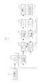
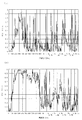
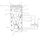
- FIG. 1 It is a longitudinal cross-sectional view which shows an example of the indoor unit of the air conditioner which concerns on Embodiment 1 of this invention. It is a block diagram which shows the signal processing apparatus which concerns on Embodiment 1 of this invention. It is the characteristic view which showed the coherence characteristic between both microphones by the installation position of a noise detection microphone and a silencing effect detection microphone. It is a longitudinal cross-sectional view which shows an example of the indoor unit of the air conditioner which concerns on Embodiment 2 of this invention. 4 is a schematic diagram for explaining a configuration example of a heat exchanger 5. FIG. It is a longitudinal cross-sectional view which shows an example of the indoor unit of the air conditioner which concerns on Embodiment 3 of this invention.
- Embodiment 1 FIG.
- a noise detection microphone corresponding to the noise detection device of the present invention
- a control speaker control sound output of the present invention
- a muffler effect detecting microphone corresponding to the muffler effect detecting device of the present invention
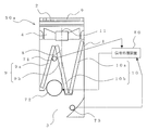
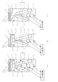
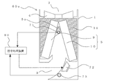
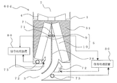
- FIG. 1 is a longitudinal sectional view showing an example of an indoor unit of an air conditioner according to Embodiment 1 of the present invention (hereinafter referred to as an indoor unit 40).
- FIG. 1 shows the left side of the drawing as the front side of the indoor unit 40. Based on FIG. 1, the structure of the indoor unit 40 is demonstrated.
- the indoor unit 40 supplies conditioned air to an air-conditioning target area such as a room by using a refrigeration cycle in which a refrigerant is circulated.
- FIG. 6, FIG. 6 to FIG. 14, FIG. 18, FIG. 20, FIG. 21, FIG. 24, and FIG. 25 show the left side of the figure as the front side of the indoor unit.
- the relationship of the size of each component may be different from the actual one.
- FIG. 1 the case where the indoor unit is a wall hanging type attached to the wall surface of the air-conditioning target area is shown as an example.
- the indoor unit 40 is mainly housed in the casing 1 in which a suction port 2 for sucking indoor air into the interior and a blower outlet 3 for supplying conditioned air to an air-conditioning target area are formed.
- the fan 4 sucks room air from the suction port 2 and blows out the conditioned air from the blower outlet 3, and is arranged in the air path from the suction port 2 to the fan 4 to exchange heat between the refrigerant and the room air.
- a heat exchanger 5 for producing And the air flow path (arrow A) is connected in the casing 1 by these components.
- the suction port 2 is formed in the upper part of the casing 1.
- the blower outlet 3 has an opening formed in the lower part of the casing 1 (more specifically, on the lower side of the front part of the casing 1).
- the fan 4 is disposed on the downstream side of the suction port 2 and on the upstream side of the heat exchanger 5, and is configured by, for example, an axial flow fan or a diagonal flow fan.
- the heat exchanger 5 is disposed on the leeward side of the fan 4. As this heat exchanger 5, for example, a fin tube heat exchanger or the like may be used.
- the suction port 2 is provided with a finger guard 6 and a filter 7.
- the blower outlet 3 is provided with a mechanism for controlling the blowing direction of the airflow, such as a vane (not shown).
- the fan 4 corresponds to the blower of the present invention.
- the indoor unit 40 includes a noise reduction unit including a noise detection microphone 71, a control speaker 72, a noise reduction effect detection microphone 73, and a signal processing device 80.
- the noise detection microphone 71 detects the operation sound (noise) of the indoor unit 40 including the blowing sound of the fan 4, and is attached to the downstream side of the heat exchanger 5.
- the muffler effect detection microphone 73 detects noise coming out of the air outlet 3 to detect the muffler effect, and forms the vicinity of the air outlet 3 on the downstream side of the heat exchanger 5 (for example, the air outlet 3 is formed). Nozzle part).
- a control speaker 72 that outputs a control sound for noise is provided on the side surface of the casing 1 (more specifically, on the lower side of the heat exchanger 5 and near the silencing effect detection microphone 73). Further, the control speaker 72 and the muffler effect detection microphone 73 are arranged so as to face the center of the air flow path from the wall of the casing 1.
- the installation position of the muffler effect detection microphone 73 is not limited to the nozzle portion of the air outlet 3 and may be an opening portion of the air outlet 3.
- the muffling effect detection microphone 73 may be attached to the lower part or the side part of the air outlet 3.
- the control speaker 72 is attached to the side surface of the casing 1, but the control speaker 72 may be attached to the front surface or the back surface of the casing 1.
- the noise detection microphone 71 is not necessarily provided on the downstream side of the heat exchanger 5, and the present invention can be achieved if the control speaker 72 and the muffler effect detection microphone 73 are provided on the downstream side of the heat exchanger 5. Can be implemented.
- the output signals of the noise detection microphone 71 and the silencing effect detection microphone 73 are input to a signal processing device 80 for generating a signal (control sound) for controlling the control speaker 72.
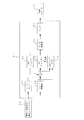
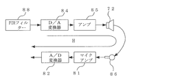
- FIG. 2 is a block diagram showing the signal processing apparatus according to Embodiment 1 of the present invention.
- the electric signal input from the noise detection microphone 71 is amplified by the microphone amplifier 81 and converted from an analog signal to a digital signal by the A / D converter 82.
- the electric signal input from the muffling effect detection microphone 73 is amplified by the microphone amplifier 81 and converted from an analog signal to a digital signal by the A / D converter 82.
- Each digital signal converted in this way is input to the FIR filter 88 and the LMS algorithm 89.
- the FIR filter 88 generates a control signal that is corrected so that the noise detected by the noise detection microphone 71 has the same amplitude and opposite phase as the noise when the noise reaches the control point where the muffler effect detection microphone 73 is installed. To do.
- This control signal is converted from a digital signal to an analog signal by the D / A converter 84, amplified by the amplifier 85, and emitted from the control speaker 72 as control sound.
- the operation of the indoor unit 40 configured as described above will be described.
- the flow of air in the indoor unit 40 will be briefly described.
- the indoor air flows into the indoor unit 40 from the suction port 2 formed in the upper part of the casing 1 by the fan 4.
- dust contained in the air is removed by the filter 7.
- This indoor air is heated or cooled by the refrigerant that is conducted through the heat exchanger 5 when passing through the heat exchanger 5 to become conditioned air.
- the conditioned air is blown out of the indoor unit 40 from the blowout port 3 formed in the lower part of the casing 1, that is, to the air-conditioning target area.
- the air that has passed through the filter 7 flows into the fan 4. That is, the air flowing into the fan 4 is less disturbed than the air flowing into the fan provided in the indoor unit of the conventional air conditioner (passed through the heat exchanger). For this reason, compared with the conventional air conditioner, the air passing through the outer peripheral part of the wing part of the fan 4 is less disturbed in the flow. Therefore, the air conditioner according to Embodiment 1 can suppress noise as compared with the indoor unit of a conventional air conditioner.
- the fan 4 is provided in the upstream of the heat exchanger 5, the indoor unit 40 is blown out from the blower outlet 3, compared with the indoor unit of the conventional air conditioner in which the fan is provided in the blower outlet.
- the generation of the swirling air flow and the generation of the wind speed distribution can be suppressed.
- there is no complicated structure such as a fan at the air outlet 3 it is easy to take measures against dew condensation caused by backflow or the like.
- the operation sound (noise) including the blowing sound of the fan 4 in the indoor unit 40 passes through the heat exchanger 5 and is detected by the noise detection microphone 71.
- the noise detected by the noise detection microphone 71 becomes a digital signal via the microphone amplifier 81 and the A / D converter 82 and is input to the FIR filter 88 and the LMS algorithm 89.
- the tap coefficient of the FIR filter 88 is updated sequentially by the LMS algorithm 89.
- h filter tap coefficient
- e error signal
- x filter input signal
- ⁇ step size parameter.
- the step size parameter ⁇ controls the filter coefficient update amount for each sampling.
- the digital signal having the tap coefficient updated by the LMS algorithm 89 and passing through the FIR filter 88 is converted to an analog signal by the D / A converter 84, amplified by the amplifier 85, and used as a control sound from the control speaker 72. It is discharged into the air flow path in the indoor unit 40.
- the noise propagated from the fan 4 through the air flow path is also heated.
- the sound after the control sound emitted from the control speaker 72 installed on the lower side of the exchanger 5 is interfered is detected.
- the signal detected by the silencing effect detection microphone 73 is handled as the error signal e of the LMS algorithm 89 described above. Then, feedback control is performed so that the error signal e approaches zero, and the tap coefficient of the FIR filter 88 is appropriately updated. As a result, noise in the vicinity of the outlet 3 can be suppressed by the control sound that has passed through the FIR filter 88.
- the coherence between the sound detected by the noise detection microphone 71 and the sound detected by the silencing effect detection microphone 73 needs to be high.
- the noise detection microphone 71 and the silencing effect detection microphone 73 are provided in a region where the airflow disturbance due to the rotation of the impeller of the fan 4 occurs (for example, in the indoor unit 40, the air flow path between the fan 4 and the heat exchanger 5).
- a pressure fluctuation component due to airflow turbulence which is a component other than the original noise, is detected, and the coherence between the two microphones decreases.
- the noise detection microphone 71 and the silencing effect detection microphone 73 are installed on the downstream side of the heat exchanger 5. Since the indoor unit 40 which is an axial flow / diagonal flow type indoor unit can install the fan 4 on the upstream side of the heat exchanger 5, the noise detection microphone 71, the silencing effect detection microphone 73, and the fan 4 are interposed between them. A heat exchanger 5 can be installed. When the noise detection microphone 71 and the silencing effect detection microphone 73 are installed in this way, the airflow turbulence generated by the fan 4 is suppressed by passing through the fins of the heat exchanger 5, and therefore the noise detection microphone 71 and the silencing effect detection microphone 73. Then, the influence by the turbulence of the airflow can be reduced. Therefore, the coherence between the noise detection microphone 71 and the silencing effect detection microphone 73 is increased, and a high silencing effect can be obtained.
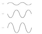
- FIG. 3 is a characteristic diagram showing the coherence characteristics between the two microphones depending on the installation positions of the noise detection microphone and the silencing effect detection microphone.
- FIG. 3A shows both microphones when the noise detection microphone 71 and the silencing effect detection microphone 73 are provided on the upstream side of the heat exchanger 5 (more specifically, between the fan 4 and the heat exchanger 5). It is the characteristic view which showed the coherence characteristic between.
- FIG. 3B is a characteristic diagram showing the coherence characteristics between the microphones when the noise detection microphone 71 and the silencing effect detection microphone 73 are provided on the downstream side of the heat exchanger 5. Comparing FIG. 3A and FIG.
- the noise detection microphone 71 and the silencing effect detection microphone 73 are arranged downstream of the heat exchanger. It can be seen that the coherence between both microphones is increased by providing it on the side.
- the distance from the installation position of the control speaker 72 to the installation position (control point) of the silencing effect detection microphone 73 is also affected by the silencing effect. That is, the length of the transmission path until the control sound emitted from the control speaker 72 reaches the control point (installation position of the mute effect detection microphone 73) also affects the muffling effect. More specifically, the amplitude characteristic and the phase characteristic of the control sound emitted from the control speaker 72 change in the transmission path until the control sound reaches the control point (the installation position of the silencing effect detection microphone 73). If the amplitude characteristic and the phase characteristic change in the transmission path and the control sound does not have the same amplitude and opposite phase as the noise, the noise reduction effect is reduced.
- the transmission path of the control sound is obtained in advance, and correction is applied in the process of generating the control sound.
- the problem of is solved.
- the transmission path becomes longer, the number of filter taps of the required transmission path becomes longer, and the calculation processing increases.
- the transmission path is long, such as when the sound speed changes due to changes in temperature or the like, the error between the calculated transmission path and the actual transmission path becomes large, and the silencing effect is reduced.
- control speaker 72 and the silencing effect detection microphone 73 close to each other.
- the transmission distance of the control sound can be shortened, and changes in the amplitude characteristic and the phase characteristic can be suppressed to a small level. That is, by installing the control speaker 72 and the muffler effect detection microphone 73 close to each other, it becomes possible to superimpose highly accurate sound waves, so that a high muffler effect can be obtained.
- the control speaker 72 is provided on the downstream side of the heat exchanger 5 where the silencing effect detection microphone 73 is installed. For this reason, the transmission path
- the indoor unit 40 which is an axial flow / diagonal flow type indoor unit can install the fan 4 on the upstream side of the heat exchanger 5, the fan 4 serving as a noise source is installed above the casing 1. be able to. For this reason, it is possible to lengthen the noise transmission path until the noise from the fan 4 is released from the air outlet 3. For this reason, the distance between the noise detection microphone 71 and the control speaker 72 can be increased by installing the control speaker 72 on the downstream side of the heat exchanger 5. In other words, it is possible to take a long calculation time until the control sound is generated for the sound detected by the noise detection microphone 71, so that it is not necessary to increase the calculation speed. Therefore, since the indoor unit 40 according to the first embodiment can reduce the specifications of the A / D converter 82 and the digital signal processor that performs signal processing, the cost can be reduced.
- the FIR filter 88 and the LMS algorithm 89 are used in the signal processing device 80.
- any adaptive signal processing circuit that brings the sound detected by the mute effect detection microphone 73 close to zero may be used.
- a filtered-X algorithm generally used in the mute method may be used.
- the signal processing device 80 does not need to be configured to perform adaptive signal processing, and may be configured to generate a control sound using a fixed tap coefficient.
- the signal processing device 80 does not have to be a digital signal processing circuit, but may be an analog signal processing circuit.
- the noise detection microphone 71, the control speaker 72, and the silencing effect detection microphone 73 are provided on the downstream side of the heat exchanger 5, there is a possibility that condensation may occur due to direct contact with cold air. May be used.
- the indoor unit 40 is an axial / diagonal flow type indoor unit in which the heat exchanger 5 is provided on the downstream side of the fan 4, the flow of air flowing into the fan 4 is It will be less disturbed. For this reason, the indoor unit 40 can suppress noise generated from the fan 4. Furthermore, the indoor unit 40 includes at least a control speaker 72 and a silencing effect detection microphone 73 on the downstream side of the heat exchanger 5 among the components of the silencing unit. For this reason, the indoor unit 40 can reduce the influence of the turbulence of the airflow generated by the fan 4 on the silencing effect detection microphone 73, and the control sound emitted from the control speaker 72 is a control point (installation position of the silencing effect detection microphone 73). It is possible to shorten the route to reach. For this reason, the indoor unit 40 can perform highly accurate noise control by the silencer unit.
- the noise detection microphone 71 is also provided on the downstream side of the heat exchanger 5. For this reason, the influence of the turbulence of the airflow generated by the fan 4 on the noise detection microphone 71 and the silencing effect detection microphone 73 can be reduced, and the coherence between the two microphones can be increased, so that a high silencing effect can be obtained. .
- the fan 4 can be provided on the upstream side of the heat exchanger 5 and above the casing 1. For this reason, the noise transmission path from the fan 4 can be lengthened, and the distance between the noise detection microphone 71 and the control speaker 72 can be increased. For this reason, since it is not necessary to increase the speed of the arithmetic processing, the cost of the indoor unit 40 can be reduced.
- Embodiment 2 By configuring the heat exchanger 5 as follows, noise can be further suppressed.
- the difference from the first embodiment will be mainly described, and the same parts as those in the first embodiment are denoted by the same reference numerals.
- the indoor unit is a wall-mounted type attached to the wall surface of the air-conditioning target area is shown as an example.
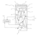
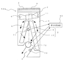
- FIG. 4 is a longitudinal sectional view showing an example of an indoor unit of an air conditioner according to Embodiment 2 of the present invention (hereinafter referred to as an indoor unit 50). Based on FIG. 4, the method of arrangement
- the indoor unit 50 supplies conditioned air to an air-conditioning target area such as a room by using a refrigeration cycle in which a refrigerant is circulated.
- the front-side heat exchanger 9 and the back-side heat exchanger 10 constituting the heat exchanger 5 are longitudinal sections (that is, indoor units) from the front side to the back side of the indoor unit 50.
- the vertical section 50 is viewed from the right side (hereinafter also referred to as the right vertical section), and is divided by the symmetry line 8.
- the symmetry line 8 divides the installation range of the heat exchanger 5 in this cross section in the left-right direction at a substantially central portion. That is, the front-side heat exchanger 9 is arranged on the front side (left side of the drawing) with respect to the symmetry line 8, and the back-side heat exchanger 10 is arranged on the back side (right side of the drawing) with respect to the symmetry line 8.
- the front-side heat exchanger 9 and the rear-side heat exchanger 10 are arranged so that the distance between the front-side heat exchanger 9 and the rear-side heat exchanger 10 is narrower with respect to the air flow direction, that is, the right side longitudinal section. It is arrange
- the front side heat exchanger 9 and the back side heat exchanger 10 are arranged so as to be inclined with respect to the flow direction of the air supplied from the fan 4. Furthermore, the air path area of the back surface side heat exchanger 10 is characterized by being larger than the air path area of the front surface side heat exchanger 9.
- the length in the longitudinal direction of the back side heat exchanger 10 is longer than the length in the longitudinal direction of the front side heat exchanger 9 in the right vertical section. Thereby, the air path area of the back surface side heat exchanger 10 is larger than the air path area of the front surface side heat exchanger 9.
- the other structure (the length of the depth direction in FIG. 4, etc.) of the front side heat exchanger 9 and the back side heat exchanger 10 is the same. That is, the heat transfer area of the back side heat exchanger 10 is larger than the heat transfer area of the front side heat exchanger 9. Further, the rotating shaft 11 of the fan 4 is installed above the symmetry line 8.
- a noise detection microphone 71, a control speaker 72, and a silencing effect detection microphone 73 are provided on the downstream side of the heat exchanger 5. These are connected to the signal processing device 80 as in the first embodiment.
- the noise reduction unit of the indoor unit 50 includes the noise detection microphone 71, the control speaker 72, the noise reduction effect detection microphone 73, and the signal processing device 80.
- the method for controlling the driving sound by the silencer unit is the same as the method described in the first embodiment.
- the indoor unit 50 configured in this manner is an axial / diagonal flow type indoor unit in which the heat exchanger 5 is provided on the downstream side of the fan 4.
- the noise generated from the can be suppressed.
- the indoor unit 50 since the indoor unit 50 includes at least the control speaker 72 and the silencing effect detection microphone 73 among the components of the silencing unit on the downstream side of the heat exchanger 5, it is generated by the fan 4 as in the first embodiment. It is possible to reduce the influence of the turbulence of the airflow on the silencing effect detection microphone 73, and to shorten the path until the control sound emitted from the control speaker 72 reaches the control point (installation position of the silencing effect detection microphone 73). Thus, highly accurate noise control can be performed by the silencer unit.
- the indoor unit 50 according to the second embodiment since the noise detection microphone 71 is also provided on the downstream side of the heat exchanger 5, the turbulence of the air flow generated by the fan 4 is the same as in the first embodiment. The influence on the noise detection microphone 71 and the silencing effect detection microphone 73 can be reduced. For this reason, since the indoor unit 50 according to the second embodiment can increase the coherence between the two microphones as in the first embodiment, a high silencing effect can be obtained.
- the fan 4 can be provided on the upstream side of the heat exchanger 5 and above the casing 1, as in the first embodiment. For this reason, the noise transmission path from the fan 4 can be lengthened, and the distance between the noise detection microphone 71 and the control speaker 72 can be increased. Therefore, the indoor unit 50 according to the second embodiment does not need to increase the speed of the arithmetic processing as in the first embodiment, and thus the cost of the indoor unit 50 can be reduced.
- an amount of air corresponding to the air passage area passes through each of the front-side heat exchanger 9 and the rear-side heat exchanger 10. That is, the air volume of the back surface side heat exchanger 10 is larger than the air volume of the front surface side heat exchanger 9. And when the air which passed each of the front side heat exchanger 9 and the back side heat exchanger 10 merges by this air volume difference, this merged air will bend to the front side (blower outlet 3 side). For this reason, it is no longer necessary to bend the airflow rapidly in the vicinity of the outlet 3, and the pressure loss in the vicinity of the outlet 3 can be reduced. Therefore, the indoor unit 50 according to the second embodiment can further suppress noise compared to the indoor unit 40 according to the first embodiment. Moreover, since the indoor unit 50 can reduce the pressure loss in the blower outlet 3 vicinity, it also becomes possible to reduce power consumption.
- an amount of air corresponding to the heat transfer area passes through each of the front side heat exchanger 9 and the back side heat exchanger 10. For this reason, the heat exchange performance of the heat exchanger 5 is improved.
- the heat exchanger 5 shown in FIG. 4 is comprised by the substantially V shape by the front side heat exchanger 9 and the back side heat exchanger 10 which were formed separately, it is not limited to this structure.
- the front-side heat exchanger 9 and the back-side heat exchanger 10 may be configured as an integrated heat exchanger (see FIG. 5).
- each of the front side heat exchanger 9 and the back side heat exchanger 10 may be configured by a combination of a plurality of heat exchangers (see FIG. 5).
- the front side is the front side heat exchanger 9 and the rear side is the back side heat exchanger 10 with respect to the symmetry line 8.
- the length in the longitudinal direction of the heat exchanger disposed on the back side of the symmetry line 8 may be longer than the length of the heat exchanger disposed on the front side of the symmetry line 8.
- the longitudinal lengths of the plurality of heat exchangers constituting the front-side heat exchanger 9 are each. Is the length of the front heat exchanger 9 in the longitudinal direction.
- the sum of the longitudinal lengths of the plurality of heat exchangers constituting the back side heat exchanger 10 is the longitudinal length of the back side heat exchanger 10.
- the heat exchanger 5 is composed of a plurality of heat exchangers (for example, when the heat exchanger 5 is composed of the front side heat exchanger 9 and the back side heat exchanger 10), the location where the arrangement gradient of the heat exchanger 5 changes ( For example, the heat exchangers do not have to be completely in contact with each other at a substantial connection point between the front-side heat exchanger 9 and the rear-side heat exchanger 10, and there may be some gaps.
- the shape of the heat exchanger 5 in the right vertical section may be partially or entirely curved (see FIG. 5).
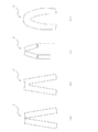
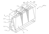
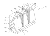
- FIG. 5 is a schematic diagram for explaining a configuration example of the heat exchanger 5.
- FIG. 5 shows the heat exchanger 5 as seen from the right vertical section. Note that the overall shape of the heat exchanger 5 shown in FIG. 5 is substantially ⁇ type, but the overall shape of the heat exchanger is merely an example.
- Fig.5 (a) you may comprise the heat exchanger 5 by a some heat exchanger.
- FIG.5 (b) you may comprise the heat exchanger 5 with an integrated heat exchanger.
- 5 (c) you may comprise the heat exchanger which comprises the heat exchanger 5 by a some heat exchanger further.
- the shape of the heat exchanger 5 may be a curved shape.
- the FIR filter 88 and the LMS algorithm 89 are used for the signal processing device 80.
- any adaptive signal processing circuit that brings the sound detected by the mute effect detection microphone 73 close to zero can be used.
- a filtered-X algorithm generally used in the mute method may be used.
- the signal processing device 80 does not need to be configured to perform adaptive signal processing, and may be configured to generate a control sound using a fixed tap coefficient.
- the signal processing device 80 does not have to be a digital signal processing circuit, but may be an analog signal processing circuit.
- the noise detection microphone 71, the control speaker 72, and the silencing effect detection microphone 73 are provided on the downstream side of the heat exchanger 5, there is a possibility that condensation may occur due to direct contact with cold air. May be used.
- Embodiment 3 FIG.
- the heat exchanger 5 may be configured as follows.
- the difference from the above-described second embodiment will be mainly described, and the same parts as those in the second embodiment are denoted by the same reference numerals.
- the case where the indoor unit is a wall-mounted type attached to the wall surface of the air-conditioning target area is shown as an example.
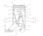
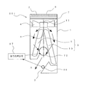
- FIG. 6 is a longitudinal sectional view showing an example of an indoor unit of an air conditioner according to Embodiment 3 of the present invention (hereinafter referred to as an indoor unit 50a). Based on FIG. 6, the method of arrangement
- the indoor unit 50a supplies conditioned air to an air-conditioning target area such as a room by using a refrigeration cycle that circulates refrigerant.
- the arrangement of the heat exchanger 5 is different from the indoor unit 50 of the second embodiment.
- the heat exchanger 5 is composed of three heat exchangers, and each of these heat exchangers is arranged with a different inclination with respect to the flow direction of the air supplied from the fan 4. And the heat exchanger 5 becomes a substantially N type in the right side longitudinal cross-section.
- the heat exchanger 9a and the heat exchanger 9b arranged on the front side of the symmetry line 8 constitute the front side heat exchanger 9
- the heat exchanger 10b constitutes the back side heat exchanger 10.
- the heat exchanger 9b and the heat exchanger 10b are configured as an integrated heat exchanger.
- the symmetry line 8 divides the installation range of the heat exchanger 5 in the right vertical section in the left-right direction at a substantially central portion.
- the length in the longitudinal direction of the back side heat exchanger 10 is longer than the length in the longitudinal direction of the front side heat exchanger 9. That is, the air volume of the back surface side heat exchanger 10 is larger than the air volume of the front surface side heat exchanger 9.
- the comparison of the lengths is the sum of the lengths of the heat exchanger groups constituting the front-side heat exchanger 9 and the sum of the lengths of the heat exchanger groups constituting the rear-side heat exchanger 10. Should be compared.
- a noise detection microphone 71, a control speaker 72, and a silencing effect detection microphone 73 are provided on the downstream side of the heat exchanger 5. These are connected to the signal processing device 80 as in the first embodiment.
- the muffling unit of the indoor unit 50a includes the noise detection microphone 71, the control speaker 72, the muffling effect detection microphone 73, and the signal processing device 80.
- the method for controlling the driving sound by the silencer unit is the same as the method described in the first embodiment.
- the indoor unit 50 a configured as described above is an axial / diagonal flow type indoor unit in which the heat exchanger 5 is provided on the downstream side of the fan 4.
- the noise generated from the can be suppressed.
- the indoor unit 50a since the indoor unit 50a includes at least the control speaker 72 and the silencing effect detection microphone 73 among the components of the silencing unit on the downstream side of the heat exchanger 5, it is generated by the fan 4 as in the first embodiment. It is possible to reduce the influence of the turbulence of the airflow on the silencing effect detection microphone 73, and to shorten the path until the control sound emitted from the control speaker 72 reaches the control point (installation position of the silencing effect detection microphone 73). Thus, highly accurate noise control can be performed by the silencer unit.
- the indoor unit 50a according to the third embodiment since the noise detection microphone 71 is also provided on the downstream side of the heat exchanger 5, the turbulence of the airflow generated by the fan 4 is the same as in the first embodiment. The influence on the noise detection microphone 71 and the silencing effect detection microphone 73 can be reduced. For this reason, since the indoor unit 50a according to the third embodiment can increase the coherence between the two microphones as in the first embodiment, a high silencing effect can be obtained.
- the fan 4 can be provided on the upstream side of the heat exchanger 5 and in the upper part of the casing 1 as in the first embodiment. For this reason, the noise transmission path from the fan 4 can be lengthened, and the distance between the noise detection microphone 71 and the control speaker 72 can be increased. Therefore, similarly to Embodiment 1, the indoor unit 50a according to Embodiment 3 does not need to have a high processing speed, so that the cost of the indoor unit 50a can be reduced.
- the air volume of the rear side heat exchanger 10 is larger than the air volume of the front side heat exchanger 9.
- this merged air is the front side (air outlet 3 To the side).
- the indoor unit 50a according to the third embodiment can further suppress noise compared to the indoor unit 40 according to the first embodiment.
- the indoor unit 50a can reduce the pressure loss in the vicinity of the blower outlet 3, it also becomes possible to reduce power consumption.
- the shape of the heat exchanger 5 is made into a substantially N type in a right side longitudinal cross section, and passes the front side heat exchanger 9 and the back side heat exchanger 10. Since the area can be increased, the wind speed passing through each area can be made smaller than that in the second embodiment. For this reason, the indoor unit 50a which concerns on this Embodiment 3 can reduce the pressure loss in the front side heat exchanger 9 and the back side heat exchanger 10 compared with the indoor unit 50 which concerns on Embodiment 2. FIG. Further, lower power consumption and noise can be achieved.
- the heat exchanger 5 shown in FIG. 6 is comprised by the substantially N type by the three heat exchangers formed separately, it is not limited to this structure.
- each of the three heat exchangers constituting the heat exchanger 5 may be configured by a combination of a plurality of heat exchangers (see FIG. 5).
- the front side is the front side heat exchanger 9 and the rear side is the back side heat exchanger 10 with respect to the symmetry line 8.
- the length in the longitudinal direction of the heat exchanger disposed on the back side of the symmetry line 8 may be longer than the length of the heat exchanger disposed on the front side of the symmetry line 8.
- the longitudinal lengths of the plurality of heat exchangers constituting the front-side heat exchanger 9 are each. Is the length of the front heat exchanger 9 in the longitudinal direction.
- the sum of the longitudinal lengths of the plurality of heat exchangers constituting the back side heat exchanger 10 is the longitudinal length of the back side heat exchanger 10.
- the heat exchanger 5 it is not necessary to incline all the heat exchangers constituting the heat exchanger 5 in the right vertical section, and a part of the heat exchangers constituting the heat exchanger 5 may be arranged vertically in the right vertical section. (See FIG. 5). Further, when the heat exchanger 5 is composed of a plurality of heat exchangers, it is not necessary that the heat exchangers are completely in contact with each other at the location where the arrangement gradient of the heat exchanger 5 is changed, and there are some gaps. May be. Moreover, the shape of the heat exchanger 5 in the right vertical section may be partially or entirely curved (see FIG. 5).
- the FIR filter 88 and the LMS algorithm 89 are used for the signal processing device 80.
- any adaptive signal processing circuit that brings the sound detected by the mute effect detection microphone 73 close to zero may be used.
- a filtered-X algorithm generally used in the mute method may be used.
- the signal processing device 80 does not need to be configured to perform adaptive signal processing, and may be configured to generate a control sound using a fixed tap coefficient.
- the signal processing device 80 does not have to be a digital signal processing circuit, but may be an analog signal processing circuit.
- the noise detection microphone 71, the control speaker 72, and the silencing effect detection microphone 73 are provided on the downstream side of the heat exchanger 5, there is a possibility that condensation may occur due to direct contact with cold air. May be used.
- Embodiment 4 FIG. Moreover, the heat exchanger 5 may be configured as follows. In the fourth embodiment, the difference from the second embodiment and the third embodiment will be mainly described, and the same reference numerals are given to the same parts as the second and third embodiments. ing. Moreover, the case where the indoor unit is a wall-mounted type attached to the wall surface of the air-conditioning target area is shown as an example.
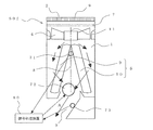
- FIG. 7 is a longitudinal sectional view showing an example of an indoor unit of an air conditioner according to Embodiment 4 of the present invention (hereinafter referred to as an indoor unit 50b). Based on FIG. 7, the method of arrangement
- the indoor unit 50b supplies conditioned air to an air-conditioning target area such as a room by using a refrigeration cycle that circulates refrigerant.
- the arrangement of the heat exchanger 5 is different from the indoor units shown in the second and third embodiments.
- the heat exchanger 5 is composed of four heat exchangers, and each of these heat exchangers is arranged with a different inclination with respect to the flow direction of the air supplied from the fan 4. And the heat exchanger 5 becomes a substantially W type in the right side longitudinal cross-section.
- the heat exchanger 9a and the heat exchanger 9b arranged on the front side of the symmetry line 8 constitute the front side heat exchanger 9
- the heat exchanger 10b constitutes the back side heat exchanger 10.
- the symmetry line 8 divides the installation range of the heat exchanger 5 in the right vertical section in the left-right direction at a substantially central portion.
- the length in the longitudinal direction of the back side heat exchanger 10 is longer than the length in the longitudinal direction of the front side heat exchanger 9. That is, the air volume of the back surface side heat exchanger 10 is larger than the air volume of the front surface side heat exchanger 9.
- the comparison of the lengths is the sum of the lengths of the heat exchanger groups constituting the front-side heat exchanger 9 and the sum of the lengths of the heat exchanger groups constituting the rear-side heat exchanger 10. Should be compared.
- a noise detection microphone 71, a control speaker 72, and a silencing effect detection microphone 73 are provided on the downstream side of the heat exchanger 5. These are connected to the signal processing device 80 as in the first embodiment.
- the muffling unit of the indoor unit 50b includes the noise detection microphone 71, the control speaker 72, the muffling effect detection microphone 73, and the signal processing device 80.
- the method for controlling the driving sound by the silencer unit is the same as the method described in the first embodiment.
- the indoor unit 50b configured as described above is an axial / diagonal flow type indoor unit in which the heat exchanger 5 is provided on the downstream side of the fan 4, and therefore, similarly to the first embodiment, the fan 4 The noise generated from the can be suppressed.
- the indoor unit 50b includes at least the control speaker 72 and the silencing effect detection microphone 73 among the components of the silencing unit on the downstream side of the heat exchanger 5, it is generated by the fan 4 as in the first embodiment. It is possible to reduce the influence of the turbulence of the airflow on the silencing effect detection microphone 73, and to shorten the path until the control sound emitted from the control speaker 72 reaches the control point (installation position of the silencing effect detection microphone 73). Thus, highly accurate noise control can be performed by the silencer unit.
- the indoor unit 50b according to the fourth embodiment since the noise detection microphone 71 is also provided on the downstream side of the heat exchanger 5, the turbulence of the air flow generated by the fan 4 is disturbed as in the first embodiment. The influence on the noise detection microphone 71 and the silencing effect detection microphone 73 can be reduced. For this reason, since the indoor unit 50b according to the fourth embodiment can increase the coherence between the two microphones as in the first embodiment, a high silencing effect can be obtained.
- the fan 4 can be provided on the upstream side of the heat exchanger 5 and in the upper part of the casing 1, as in the first embodiment. For this reason, the noise transmission path from the fan 4 can be lengthened, and the distance between the noise detection microphone 71 and the control speaker 72 can be increased. Therefore, similarly to Embodiment 1, the indoor unit 50b according to Embodiment 4 does not need to have a high processing speed, and thus the cost of the indoor unit 50b can be reduced.
- the air volume of the rear side heat exchanger 10 is larger than the air volume of the front side heat exchanger 9. Therefore, as in the second and third embodiments, when the air that has passed through each of the front-side heat exchanger 9 and the rear-side heat exchanger 10 merges due to the difference in air volume, It will bend to the side (air outlet 3 side). For this reason, it is no longer necessary to bend the airflow rapidly in the vicinity of the outlet 3, and the pressure loss in the vicinity of the outlet 3 can be reduced. Therefore, the indoor unit 50b according to the fourth embodiment can further suppress noise compared to the indoor unit 40 according to the first embodiment. Moreover, since the indoor unit 50b can reduce the pressure loss in the vicinity of the blower outlet 3, it also becomes possible to reduce power consumption.
- the indoor unit 50b which concerns on this Embodiment 4 reduces the pressure loss in the front side heat exchanger 9 and the back side heat exchanger 10 compared with the indoor unit which concerns on Embodiment 2 and Embodiment 3. Thus, further reduction in power consumption and noise can be achieved.
- the heat exchanger 5 shown in FIG. 7 is comprised by the substantially W type
- each of the four heat exchangers constituting the heat exchanger 5 may be configured by a combination of a plurality of heat exchangers (see FIG. 5).
- the front side is the front side heat exchanger 9 and the rear side is the back side heat exchanger 10 with respect to the symmetry line 8.
- the length in the longitudinal direction of the heat exchanger disposed on the back side of the symmetry line 8 may be longer than the length of the heat exchanger disposed on the front side of the symmetry line 8.
- the longitudinal lengths of the plurality of heat exchangers constituting the front-side heat exchanger 9 are each. Is the length of the front heat exchanger 9 in the longitudinal direction.
- the sum of the longitudinal lengths of the plurality of heat exchangers constituting the back side heat exchanger 10 is the longitudinal length of the back side heat exchanger 10.
- the heat exchanger 5 it is not necessary to incline all the heat exchangers constituting the heat exchanger 5 in the right vertical section, and a part of the heat exchangers constituting the heat exchanger 5 may be arranged vertically in the right vertical section. (See FIG. 5). Further, when the heat exchanger 5 is composed of a plurality of heat exchangers, it is not necessary that the heat exchangers are completely in contact with each other at the location where the arrangement gradient of the heat exchanger 5 is changed, and there are some gaps. May be. Moreover, the shape of the heat exchanger 5 in the right vertical section may be partially or entirely curved (see FIG. 5).
- the FIR filter 88 and the LMS algorithm 89 are used for the signal processing device 80.
- any adaptive signal processing circuit that brings the sound detected by the mute effect detection microphone 73 close to zero may be used.
- a filtered-X algorithm generally used in the mute method may be used.
- the signal processing device 80 does not need to be configured to perform adaptive signal processing, and may be configured to generate a control sound using a fixed tap coefficient.
- the signal processing device 80 does not have to be a digital signal processing circuit, but may be an analog signal processing circuit.
- the noise detection microphone 71, the control speaker 72, and the silencing effect detection microphone 73 are provided on the downstream side of the heat exchanger 5, there is a possibility that condensation may occur due to direct contact with cold air. May be used.
- Embodiment 5 FIG. Moreover, the heat exchanger 5 may be configured as follows. In the fifth embodiment, differences from the above-described second to fourth embodiments will be mainly described, and the same parts as those in the second to fourth embodiments are denoted by the same reference numerals. ing. Moreover, the case where the indoor unit is a wall-mounted type attached to the wall surface of the air-conditioning target area is shown as an example.
- FIG. 8 is a longitudinal sectional view showing an example of an indoor unit of an air conditioner according to Embodiment 5 of the present invention (hereinafter referred to as an indoor unit 50c). Based on FIG. 8, the arrangement
- the indoor unit 50c supplies conditioned air to an air-conditioning target area such as a room by using a refrigeration cycle that circulates refrigerant.
- the arrangement of the heat exchanger 5 is different from the indoor units shown in the second to fourth embodiments. More specifically, the indoor unit 50c of the fifth embodiment is configured by two heat exchangers (a front side heat exchanger 9 and a back side heat exchanger 10), as in the second embodiment. However, the arrangement of the front-side heat exchanger 9 and the rear-side heat exchanger 10 is different from the indoor unit 50 shown in the second embodiment.
- the front side heat exchanger 9 and the back side heat exchanger 10 are arranged with different inclinations with respect to the flow direction of the air supplied from the fan 4.
- a front side heat exchanger 9 is disposed on the front side of the symmetry line 8
- a back side heat exchanger 10 is disposed on the back side of the symmetry line 8.
- the heat exchanger 5 has a substantially ⁇ shape in the right vertical section.
- the symmetry line 8 divides the installation range of the heat exchanger 5 in the right vertical section in the left-right direction at a substantially central portion.
- the length in the longitudinal direction of the back side heat exchanger 10 is longer than the length in the longitudinal direction of the front side heat exchanger 9. That is, the air volume of the back surface side heat exchanger 10 is larger than the air volume of the front surface side heat exchanger 9.
- the comparison of the lengths is the sum of the lengths of the heat exchanger groups constituting the front-side heat exchanger 9 and the sum of the lengths of the heat exchanger groups constituting the rear-side heat exchanger 10. Should be compared.
- a noise detection microphone 71, a control speaker 72, and a silencing effect detection microphone 73 are provided on the downstream side of the heat exchanger 5. These are connected to the signal processing device 80 as in the first embodiment.
- the silencer unit of the indoor unit 50c includes the noise detection microphone 71, the control speaker 72, the silence effect detection microphone 73, and the signal processing device 80.
- the method for controlling the driving sound by the silencer unit is the same as the method described in the first embodiment.
- the indoor unit 50c configured as described above has the following internal air flow.
- the indoor air flows into the indoor unit 50 c from the suction port 2 formed in the upper part of the casing 1 by the fan 4.
- dust contained in the air is removed by the filter 7.
- this indoor air passes through the heat exchanger 5 (the front-side heat exchanger 9 and the back-side heat exchanger 10), it is heated or cooled by the refrigerant that is conducted through the heat exchanger 5 to become conditioned air.
- the air passing through the front side heat exchanger 9 flows from the front side to the back side of the indoor unit 50c.
- the air which passes the back side heat exchanger 10 flows from the back side of the indoor unit 50c to the front side.
- the conditioned air that has passed through the heat exchanger 5 (the front-side heat exchanger 9 and the back-side heat exchanger 10) passes from the outlet 3 formed in the lower part of the casing 1 to the outside of the indoor unit 50c, that is, the air-conditioning target area. Blown out.
- the indoor unit 50c configured as described above is an axial / diagonal flow type indoor unit in which the heat exchanger 5 is provided on the downstream side of the fan 4, and therefore, similarly to the first embodiment, the fan 4 The noise generated from the can be suppressed.
- the indoor unit 50c includes at least the control speaker 72 and the silencing effect detection microphone 73 on the downstream side of the heat exchanger 5 among the components of the silencing unit, similar to the first embodiment, the indoor unit 50c is generated by the fan 4. It is possible to reduce the influence of the turbulence of the airflow on the silencing effect detection microphone 73, and to shorten the path until the control sound emitted from the control speaker 72 reaches the control point (installation position of the silencing effect detection microphone 73). Thus, highly accurate noise control can be performed by the silencer unit.
- the indoor unit 50c according to the fifth embodiment since the noise detection microphone 71 is also provided on the downstream side of the heat exchanger 5, the turbulence of the airflow generated in the fan 4 is disturbed as in the first embodiment. The influence on the noise detection microphone 71 and the silencing effect detection microphone 73 can be reduced. For this reason, since the indoor unit 50c according to the fifth embodiment can increase the coherence between the two microphones as in the first embodiment, a high silencing effect can be obtained.
- the fan 4 can be provided on the upstream side of the heat exchanger 5 and in the upper part of the casing 1 as in the first embodiment. For this reason, the noise transmission path from the fan 4 can be lengthened, and the distance between the noise detection microphone 71 and the control speaker 72 can be increased. Therefore, the indoor unit 50c according to the fifth embodiment does not need to increase the speed of the arithmetic processing as in the first embodiment, so that the cost of the indoor unit 50c can be reduced.
- the air volume of the rear side heat exchanger 10 is larger than the air volume of the front side heat exchanger 9. Therefore, as in the second to fourth embodiments, when the air that has passed through each of the front-side heat exchanger 9 and the rear-side heat exchanger 10 joins due to the difference in air volume, It will bend to the side (air outlet 3 side). For this reason, it is no longer necessary to bend the airflow rapidly in the vicinity of the outlet 3, and the pressure loss in the vicinity of the outlet 3 can be reduced. Therefore, the indoor unit 50c according to the fifth embodiment can further suppress noise compared to the indoor unit 40 according to the first embodiment. Moreover, since the indoor unit 50c can reduce the pressure loss in the vicinity of the blower outlet 3, it also becomes possible to reduce power consumption.
- the flow direction of the air flowing out from the back side heat exchanger 10 is the flow from the back side to the front side.
- the indoor unit 50c according to the fifth embodiment can more easily bend the air flow after passing through the heat exchanger 5. That is, the indoor unit 50c according to the fifth embodiment can more easily control the airflow of the air blown out from the outlet 3 than the indoor unit 50 according to the second embodiment. Therefore, compared to the indoor unit 50 according to the second embodiment, the indoor unit 50c according to the fifth embodiment further eliminates the need to bend the airflow in the vicinity of the air outlet 3, and further reduces power consumption and noise. Is possible.
- the heat exchanger 5 shown in FIG. 8 is configured in a substantially ⁇ shape by the front side heat exchanger 9 and the back side heat exchanger 10 formed separately, but is not limited to this configuration.
- the front-side heat exchanger 9 and the back-side heat exchanger 10 may be configured as an integrated heat exchanger (see FIG. 5).
- each of the front side heat exchanger 9 and the back side heat exchanger 10 may be configured by a combination of a plurality of heat exchangers (see FIG. 5).
- the front side is the front side heat exchanger 9 and the rear side is the back side heat exchanger 10 with respect to the symmetry line 8.
- the length in the longitudinal direction of the heat exchanger disposed on the back side of the symmetry line 8 may be longer than the length of the heat exchanger disposed on the front side of the symmetry line 8.
- the longitudinal lengths of the plurality of heat exchangers constituting the front-side heat exchanger 9 are each. Is the length of the front heat exchanger 9 in the longitudinal direction.
- the sum of the longitudinal lengths of the plurality of heat exchangers constituting the back side heat exchanger 10 is the longitudinal length of the back side heat exchanger 10.
- the heat exchanger 5 it is not necessary to incline all the heat exchangers constituting the heat exchanger 5 in the right vertical section, and a part of the heat exchangers constituting the heat exchanger 5 may be arranged vertically in the right vertical section. (See FIG. 5). Further, when the heat exchanger 5 is composed of a plurality of heat exchangers, it is not necessary that the heat exchangers are completely in contact with each other at the location where the arrangement gradient of the heat exchanger 5 is changed, and there are some gaps. May be. Moreover, the shape of the heat exchanger 5 in the right vertical section may be partially or entirely curved (see FIG. 5).
- the FIR filter 88 and the LMS algorithm 89 are used for the signal processing device 80.
- any adaptive signal processing circuit that brings the sound detected by the mute effect detection microphone 73 close to zero may be used.
- a filtered-X algorithm generally used in the mute method may be used.
- the signal processing device 80 does not need to be configured to perform adaptive signal processing, and may be configured to generate a control sound using a fixed tap coefficient.
- the signal processing device 80 does not have to be a digital signal processing circuit, but may be an analog signal processing circuit.
- the noise detection microphone 71, the control speaker 72, and the silencing effect detection microphone 73 are provided on the downstream side of the heat exchanger 5, there is a possibility that condensation may occur due to direct contact with cold air. May be used.
- Embodiment 6 FIG. Moreover, the heat exchanger 5 may be configured as follows. In the sixth embodiment, differences from the above-described second to fifth embodiments will be mainly described, and the same parts as those in the second to fifth embodiments are denoted by the same reference numerals. Yes. Moreover, the case where the indoor unit is a wall-mounted type attached to the wall surface of the air-conditioning target area is shown as an example.
- FIG. 9 is a longitudinal sectional view showing an example of an indoor unit of an air conditioner according to Embodiment 6 of the present invention (hereinafter referred to as an indoor unit 50d). Based on FIG. 9, the arrangement
- the indoor unit 50d supplies conditioned air to an air-conditioning target area such as a room by using a refrigeration cycle that circulates refrigerant.
- the arrangement of the heat exchanger 5 is different from the indoor units shown in the second to fifth embodiments. More specifically, the indoor unit 50d of the sixth embodiment is composed of three heat exchangers as in the third embodiment. However, the arrangement of these three heat exchangers is different from the indoor unit 50a shown in the third embodiment.
- each of the three heat exchangers constituting the heat exchanger 5 is arranged with a different inclination with respect to the flow direction of the air supplied from the fan 4.
- the heat exchanger 5 has a substantially ⁇ type in the right vertical section.
- the heat exchanger 9a and the heat exchanger 9b arranged on the front side of the symmetry line 8 constitute the front side heat exchanger 9
- the heat exchanger 10b constitutes the back side heat exchanger 10. That is, in the sixth embodiment, the heat exchanger 9b and the heat exchanger 10b are configured as an integrated heat exchanger.
- the symmetry line 8 divides the installation range of the heat exchanger 5 in the right vertical section in the left-right direction at a substantially central portion.
- the length in the longitudinal direction of the back side heat exchanger 10 is longer than the length in the longitudinal direction of the front side heat exchanger 9. That is, the air volume of the back surface side heat exchanger 10 is larger than the air volume of the front surface side heat exchanger 9.
- the comparison of the lengths is the sum of the lengths of the heat exchanger groups constituting the front-side heat exchanger 9 and the sum of the lengths of the heat exchanger groups constituting the rear-side heat exchanger 10. Should be compared.
- a noise detection microphone 71, a control speaker 72, and a silencing effect detection microphone 73 are provided on the downstream side of the heat exchanger 5. These are connected to the signal processing device 80 as in the first embodiment.
- the silencer unit of the indoor unit 50d includes the noise detection microphone 71, the control speaker 72, the silence effect detection microphone 73, and the signal processing device 80.
- the method for controlling the driving sound by the silencer unit is the same as the method described in the first embodiment.
- the indoor unit 50d configured as described above is an axial / diagonal flow type indoor unit in which the heat exchanger 5 is provided on the downstream side of the fan 4, and therefore, similarly to the first embodiment, the fan 4 The noise generated from the can be suppressed.
- the indoor unit 50d includes at least the control speaker 72 and the silencing effect detection microphone 73 among the components of the silencing unit on the downstream side of the heat exchanger 5, similar to the first embodiment, the indoor unit 50d is generated by the fan 4. It is possible to reduce the influence of the turbulence of the airflow on the silencing effect detection microphone 73, and to shorten the path until the control sound emitted from the control speaker 72 reaches the control point (installation position of the silencing effect detection microphone 73). Thus, highly accurate noise control can be performed by the silencer unit.
- the indoor unit 50d according to the sixth embodiment since the noise detection microphone 71 is also provided on the downstream side of the heat exchanger 5, the turbulence of the airflow generated by the fan 4 is similar to the first embodiment. The influence on the noise detection microphone 71 and the silencing effect detection microphone 73 can be reduced. For this reason, since the indoor unit 50d according to the sixth embodiment can increase the coherence between the two microphones as in the first embodiment, a high silencing effect can be obtained.
- the fan 4 can be provided on the upstream side of the heat exchanger 5 and in the upper part of the casing 1 as in the first embodiment. For this reason, the noise transmission path from the fan 4 can be lengthened, and the distance between the noise detection microphone 71 and the control speaker 72 can be increased. Therefore, the indoor unit 50d according to the sixth embodiment does not need to increase the speed of the arithmetic processing as in the first embodiment, and thus the cost of the indoor unit 50d can be reduced.
- the air volume of the rear side heat exchanger 10 is larger than the air volume of the front side heat exchanger 9. Therefore, as in the second to fifth embodiments, when the air that has passed through each of the front-side heat exchanger 9 and the rear-side heat exchanger 10 joins due to the difference in air volume, It will bend to the side (air outlet 3 side). For this reason, it is no longer necessary to bend the airflow rapidly in the vicinity of the outlet 3, and the pressure loss in the vicinity of the outlet 3 can be reduced. Therefore, the indoor unit 50d according to the sixth embodiment can further suppress noise compared to the indoor unit 40 according to the first embodiment. Moreover, since the indoor unit 50d can reduce the pressure loss in the vicinity of the blower outlet 3, the power consumption can also be reduced.
- the flow direction of the air flowing out from the back side heat exchanger 10 is the flow from the back side to the front side.
- the indoor unit 50d according to the sixth embodiment can bend the air flow after passing through the heat exchanger 5 more easily. That is, the indoor unit 50d according to the sixth embodiment can more easily control the airflow of the air blown from the outlet 3 than the indoor unit 50a according to the third embodiment. Therefore, the indoor unit 50d according to the sixth embodiment does not need to bend the airflow in the vicinity of the air outlet 3 more rapidly than the indoor unit 50a according to the third embodiment, thereby further reducing power consumption and noise. Is possible.
- the area passing through the front side heat exchanger 9 and the back side heat exchanger 10 can be increased, so that each passes through.
- the wind speed can be made smaller than that in the fifth embodiment. For this reason, compared with Embodiment 5, the pressure loss in the front side heat exchanger 9 and the back side heat exchanger 10 can be reduced, and further reduction in power consumption and noise can be achieved.
- the heat exchanger 5 shown in FIG. 9 is comprised by the substantially ⁇ type
- each of the three heat exchangers constituting the heat exchanger 5 may be configured by a combination of a plurality of heat exchangers (see FIG. 5).
- the front side is the front side heat exchanger 9 and the rear side is the back side heat exchanger 10 with respect to the symmetry line 8.
- the length in the longitudinal direction of the heat exchanger disposed on the back side of the symmetry line 8 may be longer than the length of the heat exchanger disposed on the front side of the symmetry line 8.
- the longitudinal lengths of the plurality of heat exchangers constituting the front-side heat exchanger 9 are each. Is the length of the front heat exchanger 9 in the longitudinal direction.
- the sum of the longitudinal lengths of the plurality of heat exchangers constituting the back side heat exchanger 10 is the longitudinal length of the back side heat exchanger 10.
- the heat exchanger 5 it is not necessary to incline all the heat exchangers constituting the heat exchanger 5 in the right vertical section, and a part of the heat exchangers constituting the heat exchanger 5 may be arranged vertically in the right vertical section. (See FIG. 5). Further, when the heat exchanger 5 is composed of a plurality of heat exchangers, it is not necessary that the heat exchangers are completely in contact with each other at the location where the arrangement gradient of the heat exchanger 5 is changed, and there are some gaps. May be. Moreover, the shape of the heat exchanger 5 in the right vertical section may be partially or entirely curved (see FIG. 5).
- the FIR filter 88 and the LMS algorithm 89 are used for the signal processing device 80.
- any adaptive signal processing circuit that brings the sound detected by the mute effect detection microphone 73 close to zero can be used.
- a filtered-X algorithm generally used in the mute method may be used.
- the signal processing device 80 does not need to be configured to perform adaptive signal processing, and may be configured to generate a control sound using a fixed tap coefficient.
- the signal processing device 80 does not have to be a digital signal processing circuit, but may be an analog signal processing circuit.
- the noise detection microphone 71, the control speaker 72, and the silencing effect detection microphone 73 are provided on the downstream side of the heat exchanger 5, there is a possibility that condensation may occur due to direct contact with cold air. May be used.
- Embodiment 7 FIG. Moreover, the heat exchanger 5 may be configured as follows. In the seventh embodiment, the difference from the above-described second to sixth embodiments will be mainly described, and the same parts as those in the second to sixth embodiments are denoted by the same reference numerals. Yes. Moreover, the case where the indoor unit is a wall-mounted type attached to the wall surface of the air-conditioning target area is shown as an example.
- FIG. 10 is a longitudinal sectional view showing an example of an indoor unit of an air conditioner according to Embodiment 7 of the present invention (hereinafter referred to as an indoor unit 50e). Based on FIG. 10, the method of arrangement
- the indoor unit 50e supplies conditioned air to an air-conditioning target area such as a room by using a refrigeration cycle that circulates refrigerant.
- the arrangement of the heat exchanger 5 is different from the indoor units shown in the second to sixth embodiments. More specifically, the indoor unit 50e according to the seventh embodiment includes four heat exchangers as in the fourth embodiment. However, the arrangement of these four heat exchangers is different from the indoor unit 50b shown in the fourth embodiment.
- each of the four heat exchangers constituting the heat exchanger 5 is arranged with a different inclination with respect to the flow direction of the air supplied from the fan 4.
- the heat exchanger 5 has a substantially M shape in the right vertical section.
- the heat exchanger 9a and the heat exchanger 9b arranged on the front side of the symmetry line 8 constitute the front side heat exchanger 9
- the heat exchanger 10b constitutes the back side heat exchanger 10.
- the symmetry line 8 divides the installation range of the heat exchanger 5 in the right vertical section in the left-right direction at a substantially central portion.
- the length in the longitudinal direction of the back side heat exchanger 10 is longer than the length in the longitudinal direction of the front side heat exchanger 9. That is, the air volume of the back surface side heat exchanger 10 is larger than the air volume of the front surface side heat exchanger 9.
- the comparison of the lengths is the sum of the lengths of the heat exchanger groups constituting the front-side heat exchanger 9 and the sum of the lengths of the heat exchanger groups constituting the rear-side heat exchanger 10. Should be compared.
- a noise detection microphone 71, a control speaker 72, and a silencing effect detection microphone 73 are provided on the downstream side of the heat exchanger 5. These are connected to the signal processing device 80 as in the first embodiment.
- the muffling unit of the indoor unit 50e includes the noise detection microphone 71, the control speaker 72, the muffling effect detection microphone 73, and the signal processing device 80.
- the method for controlling the driving sound by the silencer unit is the same as the method described in the first embodiment.
- the indoor unit 50e configured as described above is an axial / diagonal flow type indoor unit in which the heat exchanger 5 is provided on the downstream side of the fan 4, and therefore, similarly to the first embodiment, the fan 4 The noise generated from the can be suppressed.
- the indoor unit 50e since the indoor unit 50e includes at least the control speaker 72 and the silencing effect detection microphone 73 among the components of the silencing unit on the downstream side of the heat exchanger 5, similar to the first embodiment, the indoor unit 50e is generated by the fan 4. It is possible to reduce the influence of the turbulence of the airflow on the silencing effect detection microphone 73, and to shorten the path until the control sound emitted from the control speaker 72 reaches the control point (installation position of the silencing effect detection microphone 73). Thus, highly accurate noise control can be performed by the silencer unit.
- the indoor unit 50e according to the seventh embodiment since the noise detection microphone 71 is also provided on the downstream side of the heat exchanger 5, the turbulence of the air flow generated by the fan 4 is disturbed as in the first embodiment. The influence on the noise detection microphone 71 and the silencing effect detection microphone 73 can be reduced. For this reason, since the indoor unit 50e according to the seventh embodiment can increase the coherence between the two microphones as in the first embodiment, a high silencing effect can be obtained.
- the fan 4 can be provided on the upstream side of the heat exchanger 5 and in the upper part of the casing 1 as in the first embodiment. For this reason, the noise transmission path from the fan 4 can be lengthened, and the distance between the noise detection microphone 71 and the control speaker 72 can be increased. Therefore, the indoor unit 50e according to the seventh embodiment does not need to increase the speed of the arithmetic processing as in the first embodiment, and thus the cost of the indoor unit 50e can be reduced.
- the air volume of the rear side heat exchanger 10 is larger than the air volume of the front side heat exchanger 9. Therefore, as in Embodiments 2 to 6, when the air that has passed through each of the front-side heat exchanger 9 and the rear-side heat exchanger 10 joins due to the difference in air volume, It will bend to the side (air outlet 3 side). For this reason, it is no longer necessary to bend the airflow rapidly in the vicinity of the outlet 3, and the pressure loss in the vicinity of the outlet 3 can be reduced. Therefore, the indoor unit 50e according to the seventh embodiment can further suppress noise compared to the indoor unit 40 according to the first embodiment. Moreover, since the indoor unit 50e can reduce the pressure loss in the vicinity of the blower outlet 3, it also becomes possible to reduce power consumption.
- the indoor unit 50e according to the seventh embodiment the flow direction of the air flowing out from the back side heat exchanger 10 is the flow from the back side to the front side. For this reason, the indoor unit 50e which concerns on this Embodiment 7 becomes easier to bend the flow of the air after passing the heat exchanger 5.
- FIG. That is, the indoor unit 50e according to the seventh embodiment can more easily control the airflow of the air blown from the outlet 3 than the indoor unit 50b according to the fourth embodiment. Therefore, in the indoor unit 50e according to the seventh embodiment, compared with the indoor unit 50b according to the fourth embodiment, it is no longer necessary to bend the airflow in the vicinity of the air outlet 3 and further reduce power consumption and noise. Is possible.
- the area which passes the front side heat exchanger 9 and the back side heat exchanger 10 can be taken large by making the shape of the heat exchanger 5 into a substantially M type in the right-side vertical cross section, it passes each. It becomes possible to make a wind speed smaller than Embodiment 5 and Embodiment 6. FIG. For this reason, compared with Embodiment 5 and Embodiment 6, the pressure loss in the front side heat exchanger 9 and the back side heat exchanger 10 can be reduced, and further reduction in power consumption and noise is possible. It becomes.
- the heat exchanger 5 shown in FIG. 10 is comprised by the substantially M type
- each of the four heat exchangers constituting the heat exchanger 5 may be configured by a combination of a plurality of heat exchangers (see FIG. 5).
- the front side is the front side heat exchanger 9 and the rear side is the back side heat exchanger 10 with respect to the symmetry line 8.
- the length in the longitudinal direction of the heat exchanger disposed on the back side of the symmetry line 8 may be longer than the length of the heat exchanger disposed on the front side of the symmetry line 8.
- the longitudinal lengths of the plurality of heat exchangers constituting the front-side heat exchanger 9 are each. Is the length of the front heat exchanger 9 in the longitudinal direction.
- the sum of the longitudinal lengths of the plurality of heat exchangers constituting the back side heat exchanger 10 is the longitudinal length of the back side heat exchanger 10.
- the heat exchanger 5 it is not necessary to incline all the heat exchangers constituting the heat exchanger 5 in the right vertical section, and a part of the heat exchangers constituting the heat exchanger 5 may be arranged vertically in the right vertical section. (See FIG. 5). Further, when the heat exchanger 5 is composed of a plurality of heat exchangers, it is not necessary that the heat exchangers are completely in contact with each other at the location where the arrangement gradient of the heat exchanger 5 is changed, and there are some gaps. May be. Moreover, the shape of the heat exchanger 5 in the right vertical section may be partially or entirely curved (see FIG. 5).
- the FIR filter 88 and the LMS algorithm 89 are used for the signal processing device 80.
- any adaptive signal processing circuit that brings the sound detected by the mute effect detection microphone 73 close to zero can be used.
- a filtered-X algorithm generally used in the mute method may be used.
- the signal processing device 80 does not need to be configured to perform adaptive signal processing, and may be configured to generate a control sound using a fixed tap coefficient.
- the signal processing device 80 does not have to be a digital signal processing circuit, but may be an analog signal processing circuit.
- the noise detection microphone 71, the control speaker 72, and the silencing effect detection microphone 73 are provided on the downstream side of the heat exchanger 5, there is a possibility that condensation may occur due to direct contact with cold air. May be used.
- Embodiment 8 FIG. Moreover, the heat exchanger 5 may be configured as follows.
- the difference from the above-described second to seventh embodiments will be mainly described, and the same parts as those in the second to seventh embodiments are denoted by the same reference numerals. Yes.
- the case where the indoor unit is a wall-mounted type attached to the wall surface of the air-conditioning target area is shown as an example.
- FIG. 11 is a longitudinal sectional view showing an example of an indoor unit of an air conditioner according to Embodiment 8 of the present invention (hereinafter referred to as an indoor unit 50f). Based on FIG. 11, the method of arrangement
- the indoor unit 50f supplies conditioned air to an air-conditioning target area such as a room by using a refrigeration cycle in which a refrigerant is circulated.
- the arrangement of the heat exchanger 5 is different from the indoor units shown in the second to seventh embodiments. More specifically, the indoor unit 50f of the eighth embodiment is composed of two heat exchangers (a front-side heat exchanger 9 and a rear-side heat exchanger 10), as in the fifth embodiment, and has a right vertical cross section. In FIG. However, in Embodiment 8, the pressure loss of the front side heat exchanger 9 and the pressure loss of the back side heat exchanger 10 are made different from each other, whereby the air volume of the front side heat exchanger 9 and the back side heat exchange are changed. The air volume of the vessel 10 is different.
- the front side heat exchanger 9 and the back side heat exchanger 10 are arranged with different inclinations with respect to the flow direction of the air supplied from the fan 4.
- a front side heat exchanger 9 is arranged on the front side of the symmetry line 8
- a back side heat exchanger 10 is arranged on the back side of the symmetry line 8.
- the heat exchanger 5 has a substantially ⁇ shape in the right vertical section.
- the length in the longitudinal direction of the rear side heat exchanger 10 and the length in the longitudinal direction of the front side heat exchanger 9 are the same. And the specifications of the front side heat exchanger 9 and the back side heat exchanger 10 are determined so that the pressure loss of the back side heat exchanger 10 becomes smaller than the pressure loss of the front side heat exchanger 9.
- the length in the short side direction (fin width) of the back side heat exchanger 10 in the right vertical section is set to the right side. It is good to make it smaller than the length (width of a fin) of the transversal direction of the front side heat exchanger 9 in a longitudinal section.
- the distance between the fins of the back surface side heat exchanger 10 may be larger than the distance between the fins of the front surface side heat exchanger 9.
- the pipe diameter of the back side heat exchanger 10 may be smaller than the pipe diameter of the front side heat exchanger 9.
- the number of pipes of the back surface side heat exchanger 10 may be smaller than the number of pipes of the front surface side heat exchanger 9.
- the symmetry line 8 divides the installation range of the heat exchanger 5 in the right vertical section in the left-right direction at a substantially central portion.
- a noise detection microphone 71, a control speaker 72, and a silencing effect detection microphone 73 are provided on the downstream side of the heat exchanger 5. These are connected to the signal processing device 80 as in the first embodiment.
- the silencing unit of the indoor unit 50f includes the noise detecting microphone 71, the control speaker 72, the silencing effect detecting microphone 73, and the signal processing device 80.
- the method for controlling the driving sound by the silencer unit is the same as the method described in the first embodiment.
- the indoor unit 50f configured as described above is an axial / diagonal flow type indoor unit in which the heat exchanger 5 is provided on the downstream side of the fan 4, and therefore, similarly to the first embodiment, the fan 4 The noise generated from the can be suppressed.
- the indoor unit 50f includes at least the control speaker 72 and the silencing effect detection microphone 73 among the components of the silencing unit on the downstream side of the heat exchanger 5, similar to the first embodiment, the indoor unit 50f is generated by the fan 4. It is possible to reduce the influence of the turbulence of the airflow on the silencing effect detection microphone 73, and to shorten the path until the control sound emitted from the control speaker 72 reaches the control point (installation position of the silencing effect detection microphone 73). Thus, highly accurate noise control can be performed by the silencer unit.
- the indoor unit 50f according to the eighth embodiment since the noise detection microphone 71 is also provided on the downstream side of the heat exchanger 5, the turbulence of the air flow generated by the fan 4 is disturbed as in the first embodiment. The influence on the noise detection microphone 71 and the silencing effect detection microphone 73 can be reduced. For this reason, since the indoor unit 50f according to the eighth embodiment can increase the coherence between the two microphones as in the first embodiment, a high silencing effect can be obtained.
- the fan 4 can be provided on the upstream side of the heat exchanger 5 and above the casing 1 as in the first embodiment. For this reason, the noise transmission path from the fan 4 can be lengthened, and the distance between the noise detection microphone 71 and the control speaker 72 can be increased. Therefore, the indoor unit 50f according to the eighth embodiment does not need to increase the speed of the arithmetic processing as in the first embodiment, so that the cost of the indoor unit 50f can be reduced.
- an amount of air corresponding to the pressure loss passes through each of the front-side heat exchanger 9 and the rear-side heat exchanger 10. That is, the air volume of the back surface side heat exchanger 10 is larger than the air volume of the front surface side heat exchanger 9. And when the air which passed each of the front side heat exchanger 9 and the back side heat exchanger 10 merges by this air volume difference, this merged air will bend to the front side (blower outlet 3 side). For this reason, it is no longer necessary to bend the airflow rapidly in the vicinity of the outlet 3, and the pressure loss in the vicinity of the outlet 3 can be reduced.
- the indoor unit 50f according to the eighth embodiment suppresses noise further than the indoor unit 40 according to the first embodiment without increasing the length of the rear side heat exchanger 10 in the right vertical section. Is possible. Moreover, since the indoor unit 50f can reduce the pressure loss in the vicinity of the blower outlet 3, the power consumption can also be reduced.
- the heat exchanger 5 shown in FIG. 11 is comprised by the substantially (LAMBDA) type
- the shape of the heat exchanger 5 in the right vertical section may be configured to be approximately V-shaped, approximately N-shaped, approximately W-shaped, approximately ⁇ -shaped or approximately M-shaped.
- each of the front side heat exchanger 9 and the back side heat exchanger 10 may be configured by a combination of a plurality of heat exchangers (see FIG. 5).
- the front side is the front side heat exchanger 9 and the rear side is the back side heat exchanger 10 with respect to the symmetry line 8. That is, the pressure loss of the heat exchanger arranged on the back side of the symmetry line 8 may be made smaller than the pressure loss of the heat exchanger arranged on the front side of the symmetry line 8.
- the sum of the pressure loss of each of the plurality of heat exchangers constituting the back side heat exchanger 10 becomes the pressure loss of the back side heat exchanger 10.
- the heat exchanger 5 is composed of a plurality of heat exchangers (for example, when the heat exchanger 5 is composed of the front side heat exchanger 9 and the back side heat exchanger 10), the location where the arrangement gradient of the heat exchanger 5 changes ( For example, the heat exchangers do not have to be completely in contact with each other at a substantial connection point between the front-side heat exchanger 9 and the rear-side heat exchanger 10, and there may be some gaps.
- the shape of the heat exchanger 5 in the right vertical section may be partially or entirely curved (see FIG. 5).
- the FIR filter 88 and the LMS algorithm 89 are used for the signal processing device 80.
- any adaptive signal processing circuit that brings the sound detected by the mute effect detection microphone 73 close to zero can be used.
- a filtered-X algorithm generally used in the mute method may be used.
- the signal processing device 80 does not need to be configured to perform adaptive signal processing, and may be configured to generate a control sound using a fixed tap coefficient.
- the signal processing device 80 does not have to be a digital signal processing circuit, but may be an analog signal processing circuit.
- the noise detection microphone 71, the control speaker 72, and the silencing effect detection microphone 73 are provided on the downstream side of the heat exchanger 5, there is a possibility that condensation may occur due to direct contact with cold air. May be used.
- Embodiment 9 FIG. Further, in Embodiments 2 to 8 described above, fan 4 may be arranged as follows. In the ninth embodiment, differences from the above-described second to eighth embodiments will be mainly described, and the same parts as those in the second to eighth embodiments are denoted by the same reference numerals. Yes. Moreover, the case where the indoor unit is a wall-mounted type attached to the wall surface of the air-conditioning target area is shown as an example.
- FIG. 12 is a longitudinal sectional view showing an example of an indoor unit of an air conditioner according to Embodiment 9 of the present invention (hereinafter referred to as an indoor unit 50g). Based on FIGS. 12 (a) to 12 (c), the arrangement of the fans 4 in the indoor unit 50g will be described.
- the indoor unit 50g supplies conditioned air to an air-conditioning target area such as a room by using a refrigeration cycle that circulates refrigerant.
- the heat exchanger 5 of the indoor unit 50g according to the ninth embodiment has the same arrangement as the indoor unit 50c of the fifth embodiment.
- the indoor unit 50g according to the ninth embodiment is different from the indoor unit 50c according to the fifth embodiment in the manner in which the fan 4 is arranged. That is, in the indoor unit 50g according to the ninth embodiment, the arrangement position of the fan 4 is determined according to the air volume and the heat transfer area of the front side heat exchanger 9 and the back side heat exchanger 10.
- the muffling unit of the indoor unit 50g includes the noise detection microphone 71, the control speaker 72, the muffling effect detection microphone 73, and the signal processing device 80.
- the method for controlling the driving sound by the silencer unit is the same as the method described in the first embodiment.
- the heat transfer area is larger than that of the front heat exchanger 9.
- the air volume of the large rear side heat exchanger 10 may be insufficient.
- the heat exchanger 5 (the front surface side heat exchanger 9 and the back surface side heat exchanger 10) may not be able to exhibit desired heat exchange performance.
- the arrangement position of the fan 4 may be moved in the back direction.
- the air volume of the back side heat exchanger 10 may be insufficient, such as when the pressure loss of the back side heat exchanger 10 is large.
- the air volume adjustment by the configuration of the front side heat exchanger 9 and the back side heat exchanger 10 passed through the front side heat exchanger 9 and the back side heat exchanger 10.
- the air that has joined later cannot be adjusted to a desired angle.
- the air merged after passing through each of the front surface side heat exchanger 9 and the back surface side heat exchanger 10 may not bend more than a desired angle.
- the arrangement position of the fan 4 may be moved in the back direction.
- the heat transfer area of the front side heat exchanger 9 may be larger than the heat transfer area of the back side heat exchanger 10.
- the arrangement position of the fan 4 may be moved in the front direction.
- the air volume of the front-side heat exchanger 9 may become larger than necessary.
- the air volume adjustment by the configuration of the front side heat exchanger 9 and the back side heat exchanger 10 passed through the front side heat exchanger 9 and the back side heat exchanger 10.
- the air which joined after passing each of the front side heat exchanger 9 and the back side heat exchanger 10 may bend more than a desired angle. In such a case, the arrangement position of the fan 4 may be moved in the front direction as shown in FIG.
- the indoor unit 50g according to the ninth embodiment is an axial / diagonal flow type indoor unit in which the heat exchanger 5 is provided on the downstream side of the fan 4, the fan 50g is similar to the first embodiment.
- the noise generated from 4 can be suppressed.
- the indoor unit 50g includes at least the control speaker 72 and the silencing effect detection microphone 73 among the components of the silencing unit on the downstream side of the heat exchanger 5, and thus is generated by the fan 4 as in the first embodiment. It is possible to reduce the influence of the turbulence of the airflow on the silencing effect detection microphone 73, and to shorten the path until the control sound emitted from the control speaker 72 reaches the control point (installation position of the silencing effect detection microphone 73). Thus, highly accurate noise control can be performed by the silencer unit.
- the indoor unit 50g according to the ninth embodiment since the noise detection microphone 71 is also provided on the downstream side of the heat exchanger 5, the turbulence of the airflow generated by the fan 4 is similar to the first embodiment. The influence on the noise detection microphone 71 and the silencing effect detection microphone 73 can be reduced. For this reason, since the indoor unit 50g according to the ninth embodiment can increase the coherence between the two microphones as in the first embodiment, a high silencing effect can be obtained.
- the fan 4 can be provided on the upstream side of the heat exchanger 5 and above the casing 1 as in the first embodiment. For this reason, the noise transmission path from the fan 4 can be lengthened, and the distance between the noise detection microphone 71 and the control speaker 72 can be increased. Therefore, the indoor unit 50g according to the ninth embodiment does not need to increase the speed of the arithmetic processing as in the first embodiment, and thus the cost of the indoor unit 50g can be reduced.
- the heat exchanger 5 shown in FIG. 12 is comprised by the substantially (LAMBDA) type
- the shape of the heat exchanger 5 in the right vertical section may be configured to be approximately V-shaped, approximately N-shaped, approximately W-shaped, approximately ⁇ -shaped, approximately M-shaped, or the like.
- each of the front side heat exchanger 9 and the back side heat exchanger 10 may be configured by a combination of a plurality of heat exchangers (see FIG. 5).
- the front side is the front side heat exchanger 9 and the rear side is the back side heat exchanger 10 with respect to the symmetry line 8.
- the longitudinal lengths of the plurality of heat exchangers constituting the front-side heat exchanger 9 are each.
- the sum of (or pressure loss) is the longitudinal length (or pressure loss) of the front-side heat exchanger 9.
- the sum of the longitudinal lengths (or pressure losses) of the plurality of heat exchangers constituting the back side heat exchanger 10 is the longitudinal direction length (or pressure loss) of the back side heat exchanger 10.
- the heat exchanger 5 is composed of a plurality of heat exchangers (for example, when the heat exchanger 5 is composed of the front side heat exchanger 9 and the back side heat exchanger 10), the location where the arrangement gradient of the heat exchanger 5 changes ( For example, the heat exchangers do not have to be completely in contact with each other at a substantial connection point between the front-side heat exchanger 9 and the rear-side heat exchanger 10, and there may be some gaps.
- the shape of the heat exchanger 5 in the right vertical section may be partially or entirely curved (see FIG. 5).
- the FIR filter 88 and the LMS algorithm 89 are used for the signal processing device 80.
- any adaptive signal processing circuit that brings the sound detected by the mute effect detection microphone 73 close to zero can be used.
- a filtered-X algorithm generally used in the mute method may be used.
- the signal processing device 80 does not need to be configured to perform adaptive signal processing, and may be configured to generate a control sound using a fixed tap coefficient.
- the signal processing device 80 does not have to be a digital signal processing circuit, but may be an analog signal processing circuit.
- the noise detection microphone 71, the control speaker 72, and the silencing effect detection microphone 73 are provided on the downstream side of the heat exchanger 5, there is a possibility that condensation may occur due to direct contact with cold air. May be used.
- Embodiment 10 FIG. Further, in the second to ninth embodiments described above, the fan 4 may be arranged as follows. In the tenth embodiment, differences from the above-described second to ninth embodiments will be mainly described, and the same parts as those in the second to ninth embodiments are denoted by the same reference numerals. Yes. Moreover, the case where the indoor unit is a wall-mounted type attached to the wall surface of the air-conditioning target area is shown as an example.
- FIG. 13 is a longitudinal sectional view showing an example of an indoor unit of an air conditioner according to Embodiment 10 of the present invention (hereinafter referred to as an indoor unit 50h). Based on FIG. 13, the arrangement
- the indoor unit 50h supplies conditioned air to an air-conditioning target area such as a room by using a refrigeration cycle in which a refrigerant is circulated.
- the heat exchanger 5 of the indoor unit 50h according to the tenth embodiment has the same arrangement as the indoor unit 50c of the fifth embodiment. However, the indoor unit 50h according to the tenth embodiment is different from the indoor unit 50c according to the fifth embodiment in the manner in which the fan 4 is arranged. That is, in the indoor unit 50h according to the tenth embodiment, the inclination of the fan 4 is determined according to the air volume and the heat transfer area of the front side heat exchanger 9 and the back side heat exchanger 10.
- a noise detection microphone 71, a control speaker 72, and a silencing effect detection microphone 73 are provided on the downstream side of the heat exchanger 5. These are connected to the signal processing device 80 as in the first embodiment.
- the muffling unit of the indoor unit 50h includes the noise detection microphone 71, the control speaker 72, the muffling effect detection microphone 73, and the signal processing device 80.
- the method for controlling the driving sound by the silencer unit is the same as the method described in the first embodiment.
- the air volume of the back side heat exchanger 10 having a larger heat transfer area than the front side heat exchanger 9 may be insufficient.
- the fan 4 cannot be moved in the front-rear direction to adjust the air volume.
- the heat exchanger 5 (the front surface side heat exchanger 9 and the back surface side heat exchanger 10) may not be able to exhibit desired heat exchange performance.
- the fan 4 may be inclined toward the back side heat exchanger 10 in the right vertical section.
- the air volume of the back side heat exchanger 10 may be insufficient.
- the fan 4 may be moved in the front-rear direction and the air volume adjustment may not be performed.
- the air merged after passing through each of the front surface side heat exchanger 9 and the back surface side heat exchanger 10 may not bend more than a desired angle.
- the fan 4 may be inclined toward the back side heat exchanger 10 in the right vertical section.
- the indoor unit 50h according to the tenth embodiment is an axial / diagonal flow type indoor unit in which the heat exchanger 5 is provided on the downstream side of the fan 4, the fan 50h is similar to the first embodiment.
- the noise generated from 4 can be suppressed.
- the indoor unit 50h includes at least the control speaker 72 and the silencing effect detection microphone 73 among the components of the silencing unit on the downstream side of the heat exchanger 5, it is generated by the fan 4 as in the first embodiment. It is possible to reduce the influence of the turbulence of the airflow on the silencing effect detection microphone 73, and to shorten the path until the control sound emitted from the control speaker 72 reaches the control point (installation position of the silencing effect detection microphone 73). Thus, highly accurate noise control can be performed by the silencer unit.
- the indoor unit 50h according to the tenth embodiment since the noise detection microphone 71 is also provided on the downstream side of the heat exchanger 5, the turbulence of the airflow generated by the fan 4 is the same as in the first embodiment. The influence on the noise detection microphone 71 and the silencing effect detection microphone 73 can be reduced. For this reason, since the indoor unit 50h according to the tenth embodiment can increase the coherence between the two microphones as in the first embodiment, a high silencing effect can be obtained.
- the fan 4 can be provided on the upstream side of the heat exchanger 5 and above the casing 1 as in the first embodiment. For this reason, the noise transmission path from the fan 4 can be lengthened, and the distance between the noise detection microphone 71 and the control speaker 72 can be increased. Therefore, similarly to Embodiment 1, the indoor unit 50h according to the tenth embodiment does not need to increase the speed of the arithmetic processing, so that the cost of the indoor unit 50h can be reduced.
- the heat exchanger 5 shown in FIG. 13 is configured in a substantially ⁇ shape by the front side heat exchanger 9 and the back side heat exchanger 10 formed separately, it is not limited to this configuration.
- the shape of the heat exchanger 5 in the right vertical section may be configured to be approximately V-shaped, approximately N-shaped, approximately W-shaped, approximately ⁇ -shaped or approximately M-shaped.
- each of the front side heat exchanger 9 and the back side heat exchanger 10 may be configured by a combination of a plurality of heat exchangers (see FIG. 5).
- the front side is the front side heat exchanger 9 and the rear side is the back side heat exchanger 10 with respect to the symmetry line 8.
- the longitudinal lengths of the plurality of heat exchangers constituting the front-side heat exchanger 9 are each.
- the sum of (or pressure loss) is the longitudinal length (or pressure loss) of the front-side heat exchanger 9.
- the sum of the longitudinal lengths (or pressure losses) of the plurality of heat exchangers constituting the back side heat exchanger 10 is the longitudinal direction length (or pressure loss) of the back side heat exchanger 10.
- the heat exchanger 5 is composed of a plurality of heat exchangers (for example, when the heat exchanger 5 is composed of the front side heat exchanger 9 and the back side heat exchanger 10), the location where the arrangement gradient of the heat exchanger 5 changes ( For example, the heat exchangers do not have to be completely in contact with each other at a substantial connection point between the front-side heat exchanger 9 and the rear-side heat exchanger 10, and there may be some gaps.
- the shape of the heat exchanger 5 in the right vertical section may be partially or entirely curved (see FIG. 5).
- the FIR filter 88 and the LMS algorithm 89 are used for the signal processing device 80.
- any adaptive signal processing circuit that brings the sound detected by the muffling effect detection microphone 73 close to zero may be used.
- a filtered-X algorithm generally used in the mute method may be used.
- the signal processing device 80 does not need to be configured to perform adaptive signal processing, and may be configured to generate a control sound using a fixed tap coefficient.
- the signal processing device 80 does not have to be a digital signal processing circuit, but may be an analog signal processing circuit.
- the noise detection microphone 71, the control speaker 72, and the silencing effect detection microphone 73 are provided on the downstream side of the heat exchanger 5, there is a possibility that condensation may occur due to direct contact with cold air. May be used.
- Embodiment 11 FIG.
- the machine will be described.
- items not particularly described are the same as those in the first to tenth embodiments, and the same functions and configurations are described using the same reference numerals.
- FIG. 14 is a longitudinal sectional view showing an example of an indoor unit of an air conditioner according to Embodiment 11 of the present invention (hereinafter referred to as an indoor unit 50i).
- the indoor unit 50i supplies conditioned air to an air-conditioning target area such as a room by using a refrigeration cycle that circulates refrigerant.
- the heat exchanger 5 of the indoor unit 50i according to the eleventh embodiment has the same arrangement as the indoor unit 50c of the fifth embodiment.
- the difference between the indoor unit 50i according to the eleventh embodiment and the indoor unit 50c according to the fifth embodiment is that a microphone used for active silencing is different. More specifically, the indoor unit 50c according to the fifth embodiment uses the two microphones (the noise detection microphone 71 and the silencing effect detection microphone 73) to generate the control sound by the signal processing device 80. On the other hand, in the indoor unit 50i of the eleventh embodiment, the noise detection microphone 71 and the silencing effect detection microphone 73 are replaced with a noise / silencing effect detection microphone 86 which is one microphone. Further, since the signal processing method differs depending on the microphone used for dynamic silencing, the indoor unit 50i of the eleventh embodiment is different from the signal processing device 80 of the indoor unit 50c according to the fifth embodiment. A processing device 87 is used.
- the indoor unit 50 i includes a muffling unit including a control speaker 72, a noise / muffling effect detection microphone 86, and a signal processing device 87.
- the noise / muffling effect detection microphone 86 is attached in the vicinity of the air outlet 3 downstream of the heat exchanger 5 (for example, the nozzle portion forming the air outlet 3).
- the noise / muffling effect detection microphone 86 detects the sound after the control sound emitted from the control speaker 72 interferes with the operation sound (noise) of the indoor unit 50 i including the blowing sound of the fan 4.
- a control speaker 72 that outputs a control sound for noise is provided on the side surface of the casing 1 (more specifically, on the lower side of the heat exchanger 5 and near the noise / silencing effect detection microphone 86).
- the control speaker 72 and the noise / silencing effect detection microphone 86 are arranged below the heat exchanger 5 so as to face the center of the air flow path from the wall of the casing 1.
- the installation position of the noise / muffling effect detection microphone 86 is not limited to the nozzle portion of the air outlet 3, but may be an opening portion of the air outlet 3.
- the noise / muffling effect detection microphone 86 may be attached to the lower part or the side part of the air outlet 3.
- the control speaker 72 is attached to the side surface of the casing 1, but the control speaker 72 may be attached to the front surface or the back surface of the casing 1.
- the output signal of the noise / muffling effect detection microphone 86 is input to a signal processing device 87 for generating a signal (control sound) for controlling the control speaker 72.
- FIG. 15 is a block diagram showing a signal processing apparatus according to Embodiment 11 of the present invention.
- the electric signal converted from the sound signal by the noise / muffling effect detection microphone 86 is amplified by the microphone amplifier 81 and converted from an analog signal to a digital signal by the A / D converter 82.
- the converted digital signal is input to the LMS algorithm 89.
- a difference signal from the signal obtained by convolving the FIR filter 90 with the output signal of the FIR filter 88 is input to the FIR filter 88 and the LMS algorithm 89.
- the difference signal is subjected to a convolution operation by the tap coefficient calculated by the LMS algorithm 89 by the FIR filter 88, converted from a digital signal to an analog signal by the D / A converter 84, and amplified by the amplifier 85.
- the sound is emitted from the control speaker 72 as a control sound.
- FIG. 16 shows the sound waveform after interference between the noise and the control sound (a in FIG. 16), the control sound waveform (b in FIG. 16), and the noise waveform (c in FIG. 16).
- b + c a. Therefore, in order to obtain c from a, the difference between a and b may be taken. That is, the noise to be silenced can be created from the difference between the sound after interference detected by the noise / silencing effect detection microphone 86 and the control sound.
- FIG. 17 shows a route from the control signal output from the FIR filter 88 being output as the control sound from the control speaker 72 to being detected by the noise / silence effect detection microphone 86 and being input to the signal processor 87.
- the control signal output from the FIR filter 88 passes through a path from the D / A converter 84, the amplifier 85, and the control speaker 72 to the noise / silence effect detection microphone 86, and then the noise / silence effect detection microphone 86, the microphone amplifier 81, It passes through the path of the A / D converter 82.
- the FIR filter 90 in FIG. 15 estimates the transfer characteristic H.
- the control sound can be estimated as the signal b detected by the noise / silence effect detection microphone 86, and after the interference detected by the noise / silence effect detection microphone 86
- the noise c to be silenced is generated by taking the difference from the sound a.
- the noise c to be silenced generated in this way is supplied to the LMS algorithm 89 and the FIR filter 88 as an input signal.
- the digital signal that has passed through the FIR filter 88 whose tap coefficient has been updated by the LMS algorithm 89 is converted into an analog signal by the D / A converter 84, amplified by the amplifier 85, and sent from the control speaker 72 as control sound to the indoor unit 50i. It is discharged into the internal air flow path.
- the noise / silencing effect detection microphone 86 attached to the nozzle portion of the air outlet 3 on the downstream side of the heat exchanger 5 of the indoor unit 50i, the noise propagated from the fan 4 through the air flow path is Similarly, the sound after the control sound emitted from the control speaker 72 installed on the lower side of the heat exchanger 5 is interfered is detected.
- the signal detected by the noise / muffling effect detection microphone 86 is handled as the error signal e of the LMS algorithm 89 described above. Then, feedback control is performed so that the error signal e approaches zero, and the tap coefficient of the FIR filter 88 is appropriately updated. As a result, noise in the vicinity of the outlet 3 can be suppressed by the control sound that has passed through the FIR filter 88.
- the noise / noise reduction effect detection microphone 86 does not detect a pressure fluctuation component due to airflow turbulence.
- the noise / silencing effect detection microphone 86 is installed on the downstream side of the heat exchanger 5.
- the fan 4 can be installed on the upstream side of the heat exchanger 5, and therefore the heat exchanger between the noise 86 and the fan 4 is detected. 5 can be installed.
- the noise / muffling effect detection microphone 86 is installed in this manner, airflow turbulence generated in the fan 4 is suppressed by passing through the fins of the heat exchanger 5. For this reason, the noise / silencing effect detection microphone 86 is less affected by airflow turbulence and can provide a high silencing effect.
- the noise reduction effect is affected by the distance from the installation position of the control speaker 72 to the installation position (control point) of the noise / silence effect detection microphone 86. That is, the silencing effect is also affected by the length of the transmission path until the control sound emitted from the control speaker 72 reaches the control point (the installation position of the noise / silencing effect detection microphone 86). More specifically, the amplitude characteristic and the phase characteristic of the control sound emitted from the control speaker 72 change in the transmission path until it reaches the control point (the installation position of the noise / silencing effect detection microphone 86). If the amplitude characteristic and the phase characteristic change in the transmission path and the control sound does not have the same amplitude and opposite phase as the noise, the noise reduction effect is reduced.
- the transmission path of the control sound is obtained in advance, and correction is applied in the process of generating the control sound.
- the problem of is solved.
- the transmission path becomes longer, the number of filter taps of the required transmission path becomes longer, and the calculation processing increases.
- the transmission path is long, such as when the sound speed changes due to changes in temperature or the like, the error between the calculated transmission path and the actual transmission path becomes large, and the silencing effect is reduced.
- control speaker 72 and the noise / silencing effect detecting microphone 86 close to each other.
- the control speaker 72 and the noise / silence effect detection microphone 86 in this manner, the transmission distance of the control sound can be shortened, and changes in the amplitude characteristic and the phase characteristic can be suppressed to a small level. That is, by installing the control speaker 72 and the noise / silencing effect detection microphone 86 close to each other, it becomes possible to superimpose highly accurate sound waves, and thus a high silencing effect can be obtained.
- the control speaker 72 is provided on the downstream side of the heat exchanger 5 where the noise / muffling effect detecting microphone 86 is installed. For this reason, the transmission path
- the heat exchanger 5 shown in FIG. 14 is comprised by the substantially (LAMBDA) type
- the shape of the heat exchanger 5 in the right vertical section may be configured to be approximately V-shaped, approximately N-shaped, approximately W-shaped, approximately ⁇ -shaped, approximately M-shaped, or the like.
- each of the front side heat exchanger 9 and the back side heat exchanger 10 may be configured by a combination of a plurality of heat exchangers (see FIG. 5).
- the front side is the front side heat exchanger 9 and the rear side is the back side heat exchanger 10 with respect to the symmetry line 8.
- the longitudinal lengths of the plurality of heat exchangers constituting the front-side heat exchanger 9 are each.
- the sum of (or pressure loss) is the longitudinal length (or pressure loss) of the front-side heat exchanger 9.
- the sum of the longitudinal lengths (or pressure losses) of the plurality of heat exchangers constituting the back side heat exchanger 10 is the longitudinal direction length (or pressure loss) of the back side heat exchanger 10.
- the heat exchanger 5 is composed of a plurality of heat exchangers (for example, when the heat exchanger 5 is composed of the front side heat exchanger 9 and the back side heat exchanger 10), the location where the arrangement gradient of the heat exchanger 5 changes ( For example, the heat exchangers do not have to be completely in contact with each other at a substantial connection point between the front-side heat exchanger 9 and the rear-side heat exchanger 10, and there may be some gaps.
- the shape of the heat exchanger 5 in the right vertical section may be partially or entirely curved (see FIG. 5).
- the FIR filter 88 and the LMS algorithm 89 are used in the signal processing device 80.
- any adaptive signal processing circuit may be used as long as the sound detected by the noise / muffling effect detection microphone 86 approaches zero.
- a filtered-X algorithm generally used in the active silencing method may be used.
- the signal processing device 87 does not need to be configured to perform adaptive signal processing, and may be configured to generate a control sound with a fixed tap coefficient.
- the signal processing device 87 does not have to be a digital signal processing circuit, but may be an analog signal processing circuit.
- condensation may occur due to direct contact with cold air. Also good.
- the indoor unit 50i is an axial / diagonal flow type indoor unit in which the heat exchanger 5 is provided on the downstream side of the fan 4, the flow of air flowing into the fan 4 is It will be less disturbed. For this reason, the indoor unit 50i can suppress the noise generated from the fan 4. Furthermore, the indoor unit 50i includes at least a control speaker 72 and a noise / silence effect detection microphone 86 on the downstream side of the heat exchanger 5 among the components of the silencing unit.
- the indoor unit 50i can reduce the influence of the turbulence of the airflow generated by the fan 4 on the noise / silence effect detection microphone 86, and the control sound emitted from the control speaker 72 is controlled by the control point (noise / silence effect detection microphone 86). It is possible to shorten the route to reach the installation position. For this reason, the indoor unit 50i can perform highly accurate noise control by the silencing unit.
- Embodiment 12 By dividing the air path in the casing 1 of the indoor unit shown in the first to eleventh embodiments, noise can be further suppressed.
- items not particularly described in the twelfth embodiment are the same as those in the first to eleventh embodiments, and the same functions and configurations are described using the same reference numerals.
- the case where the air passage in the casing 1 of the indoor unit 50c according to the fifth embodiment is divided will be described.
- the air path in the casing 1 of the indoor unit shown in the first to fourth embodiments and the sixth to eleventh embodiments as in the twelfth to sixteenth embodiments.
- the effects shown in the twelfth to sixteenth embodiments can be obtained.
- FIG. 18 is a schematic longitudinal sectional view showing an example of an indoor unit of an air conditioner according to Embodiment 12 of the present invention (hereinafter referred to as an indoor unit 60a).
- FIG. 19 is a perspective view showing the indoor unit 60a.
- the casing 1 and the partition plate 31 are shown in a transparent manner for easy understanding of the drawing.
- the installation positions of the noise detection microphone 71, the control speaker 72, and the silencing effect detection microphone 73 are indicated by imaginary lines (two-dot chain lines).
- the signal processing device 80 is not shown.
- indoor units of air conditioners often have a large installation fan because of limited installation space. For this reason, in order to obtain a desired air flow rate, a plurality of fans having an appropriate size may be arranged in parallel.
- a plurality of fans having an appropriate size may be arranged in parallel in the indoor unit 60a according to the twelfth embodiment, as shown in FIG. 19, three fans 4 are arranged in parallel along the longitudinal direction (left-right direction) of the casing 1.
- the partition unit 31 is provided between the adjacent fans 4 in the indoor unit 60a according to the twelfth embodiment.
- These partition plates 31 are installed between the heat exchanger 5 and the fan 4. That is, the air path between the heat exchanger 5 and the fan 4 is divided into a plurality of air paths (three in the twelfth embodiment). Since the partition plate 31 is installed between the heat exchanger 5 and the fan 4, the end on the side in contact with the heat exchanger 5 has a shape along the heat exchanger 5. More specifically, since the heat exchanger 5 is arranged in the ⁇ shape, the end portion of the partition plate 31 on the heat exchanger 5 side is also in the ⁇ shape.
- the end of the partition plate 31 on the fan 4 side has a shape in which air and sound hardly leak into the adjacent air passage in consideration of the shape of the suction port 2 and the fan 4.
- the end of the partition plate 31 on the fan 4 side is disposed in the vicinity of the fan 4.
- the partition plate 31 can be formed of various materials.
- the partition plate 31 may be formed of a metal such as steel or aluminum.
- the partition plate 31 may be formed of resin or the like.
- the heat exchanger 5 becomes high temperature during the heating operation, when the partition plate 31 is formed of a low melting point material such as resin, the heat exchanger 5 is slightly between the partition plate 31 and the heat exchanger 5. A good space should be formed.
- the partition plate 31 is made of a material having a high melting point such as aluminum or steel, the partition plate 31 may be disposed in contact with the heat exchanger 5, and the partition plate 31 is inserted between the fins of the heat exchanger 5. May be.
- a noise detection microphone 71, a control speaker 72, and a silencing effect detection microphone 73 are provided on the downstream side of the heat exchanger 5. More specifically, the noise detection microphone 71 and the control speaker 72 are provided on the side surface of the casing 1.
- the silencing effect detection microphone 73 is provided in the vicinity of the air outlet 3 on the downstream side of the heat exchanger 5 (for example, the nozzle portion forming the air outlet 3). These are connected to the signal processing device 80 as in the first embodiment.
- the muffling unit of the indoor unit 60a includes the noise detection microphone 71, the control speaker 72, the muffling effect detection microphone 73, and the signal processing device 80.
- the method for controlling the driving sound by the silencer unit is the same as the method described in the first embodiment.
- a noise reduction unit including the noise detection microphone 71, the control speaker 72, the noise reduction effect detection microphone 73, and the signal processing device 80 is used.
- the control speaker 72, the noise / noise reduction effect detection microphone 86 are used.
- a silencer unit including the signal processor 87 may be used.
- noise that has passed through a plurality of flow paths (more specifically, noise generated from the fan 4) is silenced by one silencing unit. You may mute the noise which passed through a plurality of channels using.
- a silencer unit may be provided for each flow path. Noise can be further suppressed by providing a silencer unit for each channel.
- FIG. 20 is a longitudinal sectional view showing another example of the indoor unit for an air-conditioning apparatus according to Embodiment 12 of the present invention.
- the noise detection microphone 71 may be provided on the fixing bracket 5 a on the downstream side of the heat exchanger 5.
- the control speaker 72 may be provided in the vicinity of the air outlet 3 on the downstream side of the heat exchanger 5 (for example, the nozzle portion forming the air outlet 3).
- the silencing effect detection microphone 73 may be provided on the side surface of the casing 1 so as to be downstream of the heat exchanger 5.
- the air supplied from each fan 4 4 flows into the air passage formed below the air passage 4. For this reason, the noise generated from each fan 4 can be separated for each divided air path. That is, the noise that flows out from each divided air path has a reduced crosstalk noise component from the adjacent fan 4. Therefore, since the coherence between the noise detection microphone 71 and the silencing effect detection microphone 73 can be increased, a high silencing effect can be obtained.
- the divided air passages are formed in a substantially rectangular shape with one side being L1 and L2 in plan view. That is, the width of the divided air path is L1 and L2. For this reason, for example, when L1 ⁇ L2, when the noise generated by the fan 4 passes through the divided air path, the noise having a frequency f whose half wavelength is shorter than L1 is converted into a plane wave (one-dimensional). Propagate. For example, when L1> L2, when the noise generated by the fan 4 passes through the divided air path, the noise having a frequency f whose half wavelength is shorter than L2 is converted into a plane wave (one-dimensional). Propagate.
- the indoor unit 60a configured as described above since the air passages in the casing 1 are divided by the partition plate 31, noise flowing out from each divided air passage is crossed by the adjacent fan 4. The talk noise component is reduced. For this reason, since the coherence of the noise detection microphone 71 and the silencing effect detection microphone 73 can be further increased, noise can be further suppressed as compared with the indoor unit 50c according to the fifth embodiment. Further, in the indoor unit 60a configured as described above, since the noise propagating in the casing 1 can be made into a plane wave (one-dimensional), the noise is further suppressed as compared with the indoor unit 50c according to the fifth embodiment. Is possible.
- the partition plate 31 also has an effect that the efficiency of the fan 4 is increased. This is because the air blown out from the adjacent fans 4 can be prevented from interfering on the downstream side, and energy loss generated in each fan 4 can be suppressed by this interference.
- each partition plate 31 does not need to be formed by a single plate, and may be formed by a plurality of plates.
- the partition plate 31 may be divided into two parts on the front side heat exchanger 9 side and the back side heat exchanger 10 side. If there is no gap at the joint between the plates constituting the partition plate 31, the same silencing effect as when the partition plate 31 is formed by a single plate can be obtained. By dividing the partition plate 31 into a plurality of parts, the assembling property of the partition plate 31 is improved.
- Embodiment 13 FIG. In Embodiment 12, only the air path between the fan 4 and the heat exchanger 5 is divided by the partition plate 31. In addition to the air path between the fan 4 and the heat exchanger 5, the air path on the downstream side of the heat exchanger 5 can also be divided by the partition plate.
- items that are not particularly described are the same as those in the twelfth embodiment, and the same functions and configurations are described using the same reference numerals.
- FIG. 21 is a schematic longitudinal sectional view showing an example of an indoor unit of an air conditioner according to Embodiment 13 of the present invention (hereinafter referred to as an indoor unit 60b).
- a partition plate 31a is provided between the heat exchanger 5 and the outlet 3 in addition to the partition plate 31 between the fan 4 and the heat exchanger 5.
- the number of partition plates 31 a provided between the heat exchanger 5 and the air outlet 3 is the same as the number of partition plates 31 provided between the fan 4 and the heat exchanger 5. It is provided below. More specifically, the partition plate 31a is provided substantially parallel to the partition plate 31 in plan view. Further, the partition plate 31a is provided so as to substantially overlap with the partition plate 31 in a plan view. Thereby, the air resistance by having provided the partition plate 31a is suppressed.
- the end portion (upper end portion) of the partition plate 31a on the heat exchanger 5 side is also in the ⁇ shape.
- the partition plate 31a is arrange
- the heat exchanger 5 is at a low temperature. For this reason, moisture in the air is condensed, and water droplets adhere to the surface of the heat exchanger 5. If the heat exchanger 5 and the partition plate 31a are in contact with each other, water droplets attached to the surface of the heat exchanger 5 will move to the partition plate 31a.
- the water droplets that have moved to the partition plate 31a travel along the partition plate 31 to the air outlet 3 and are entrained by the air blown from the air outlet 3 and are scattered around. This splashing of water droplets may cause the user to feel uncomfortable and is a phenomenon that should not be applied to the air conditioner. For this reason, in order to prevent the water droplet adhering to the surface of the heat exchanger 5 from scattering from the blower outlet 3, the partition plate 31a is arrange
- the noise detection microphone 71, the control speaker 72, and the silencing effect detection microphone 73 are provided on the downstream side of the heat exchanger 5. More specifically, the noise detection microphone 71 is provided on the fixture 5 a on the downstream side of the heat exchanger 5.
- the control speaker 72 and the silencing effect detection microphone 73 are provided in the vicinity of the air outlet 3 on the downstream side of the heat exchanger 5 (for example, the nozzle portion forming the air outlet 3). That is, the noise reduction unit of the indoor unit 60 b includes the noise detection microphone 71, the control speaker 72, the noise reduction effect detection microphone 73, and the signal processing device 80.
- the method for controlling the driving sound by the silencer unit is the same as the method described in the first embodiment.
- a noise detection microphone 71, a control speaker 72, and a silencing effect detection microphone 73 are provided for each divided air path.
- the mute unit including the noise detection microphone 71, the control speaker 72, the mute effect detection microphone 73, and the signal processing device 80 is used.
- the control speaker 72, the noise / mute effect detection microphone 86 are used.
- a silencer unit including the signal processor 87 may be used.
- the installation positions of the noise detection microphone 71, the control speaker 72, and the silencing effect detection microphone 73 are not limited to the positions shown in FIG.
- the noise detection microphone 71, the control speaker 72, and the mute effect detection microphone 73 may be provided on the partition plate 31a.
- the muffling effect detection microphone 73 when the muffling effect detection microphone 73 is provided on the downstream side of the divided air path (that is, provided at a location where the air flowing out from the divided air path joins), it is provided on the downstream side of the divided air path.
- the muffled effect detection microphone 73 thus made may be shared as in the twelfth embodiment.
- the noise detection microphone 71 and the control speaker 72 are provided on the downstream side of the divided air path, they may of course be shared.
- the noise generated by the fan 4 can be converted into a plane wave even between the heat exchanger 5 and the air outlet 3 by arranging the partition plate 31a. .
- the noise detection microphone 71, the control speaker 72, and the muffling effect detection microphone 73 can be installed in the divided air path.
- the indoor unit 60b according to the thirteenth embodiment can further increase the coherence between the noise detection microphone 71 and the silencing effect detection microphone 73 as compared with the indoor unit 60a according to the twelfth embodiment.
- the indoor unit 60b according to the thirteenth embodiment further improves the noise suppression effect by making the noise into a plane wave (one-dimensional) compared to the indoor unit 60a according to the twelfth embodiment. Therefore, the indoor unit 60b according to the thirteenth embodiment can further suppress noise compared to the indoor unit 60a according to the twelfth embodiment.
- the lower end of the partition plate 31a is extended to the outlet 3; however, the lower end of the partition 31a is connected to the heat exchanger 5, the outlet 3, and Of course, it may be between.
- Embodiment 14 FIG.
- the number of fans 4 and the number of divided air passages are the same. Not limited to this, the number of divisions of the air passage may be larger than the number of fans 4.
- items not particularly described are the same as those in the twelfth or thirteenth embodiment, and the same functions and configurations are described using the same reference numerals.
- FIG. 22 is a perspective view showing an example of an indoor unit of an air conditioner according to Embodiment 14 of the present invention (hereinafter referred to as an indoor unit 60c).
- an indoor unit 60c an indoor unit of an air conditioner according to Embodiment 14 of the present invention
- the casing 1 and the partition plate 31 are shown through. Further, the installation positions of the noise detection microphone 71, the control speaker 72, and the silencing effect detection microphone 73 are indicated by imaginary lines (two-dot chain lines).
- the signal processing device 80 is not shown.
- a partition plate 37 is provided between the partition plates 31. That is, in the fourteenth embodiment, the air passage divided in the twelfth embodiment is further divided by the partition plate 37.
- the partition plate 37 is arrange
- the partition plate 37 may be formed of a metal such as steel or aluminum.
- the partition plate 37 may be formed of resin or the like.
- the shape of the end portion of the partition plate 37 on the side of the heat exchanger 5 is substantially ⁇ -shaped along the heat exchanger 5.
- the partition plate 37 is formed of a material having a low melting point such as a resin
- the heat exchanger 5 becomes a high temperature during the heating operation. Therefore, a slight space is formed between the partition plate 37 and the heat exchanger 5. It is good to form.
- the partition plate 37 is made of a material having a high melting point such as aluminum or steel, the partition plate 37 may be disposed so as to be in contact with the heat exchanger 5, and the partition plate 37 is inserted between the fins of the heat exchanger 5. May be.
- the shape of the end portion of the partition plate 37 on the fan 4 side is substantially parallel to the exit surface of the fan 4. Note that the shape of the partition plate 37 on the fan 4 side may be a mountain shape in which the vicinity of the rotation center of the fan 4 is increased and becomes lower toward the periphery.
- the height of the end of the partition plate 37 on the fan 4 side may be set as follows.
- the partition plate 37 becomes an air flow resistance. For this reason, when the fan 4 and the heat exchanger 5 are close, it is better to make the distance between the fan 4 side end of the partition plate 37 and the fan 4 as far as possible. Therefore, when the fan 4 and the heat exchanger 5 are close to each other, the height of the end portion of the partition plate 37 on the fan 4 side is almost the same as the upper end portion of the heat exchanger 5 (position closest to the fan 4). That's fine.
- the fan 4 side end of the partition plate 37 may be disposed in the middle of the inclined surface of the heat exchanger 5.
- the partition plate 37 does not serve as an air flow resistance. For this reason, when there is a sufficient distance between the fan 4 and the heat exchanger 5, the height of the end of the partition plate 37 on the fan 4 side is set to the upper end of the heat exchanger 5 (the position closest to the fan 4). ) Higher. By bringing the end of the partition plate 37 on the fan 4 side closer to the fan 4, the range in which noise generated from the fan 4 can be converted into a plane wave increases.
- a noise detection microphone 71, a control speaker 72, and a silencing effect detection microphone 73 are provided on the downstream side of the heat exchanger 5. More specifically, the noise detection microphone 71 and the control speaker 72 are provided on the side surface of the casing 1.
- the silencing effect detection microphone 73 is provided in the vicinity of the air outlet 3 on the downstream side of the heat exchanger 5 (for example, the nozzle portion forming the air outlet 3). These are connected to the signal processing device 80 as in the first embodiment.
- the muffling unit of the indoor unit 60c includes the noise detection microphone 71, the control speaker 72, the muffling effect detection microphone 73, and the signal processing device 80.
- the method for controlling the driving sound by the silencer unit is the same as the method described in the first embodiment.
- the mute unit including the noise detection microphone 71, the control speaker 72, the mute effect detection microphone 73, and the signal processing device 80 is used.
- the control speaker 72, the noise / mute effect detection microphone 86 are used.
- a silencer unit including the signal processor 87 may be used.
- the indoor unit 60c according to the fourteenth embodiment silences the noise that has passed through the plurality of flow paths by using one silencer unit, but the noise that has passed through the plurality of channels by using the plurality of silencer units. You may mute.
- a silencer unit may be provided for each flow path. Noise can be further suppressed by providing a silencer unit for each channel.
- the installation positions of the noise detection microphone 71, the control speaker 72, and the silencing effect detection microphone 73 are not limited to the positions shown in FIG.
- the noise detection microphone 71 may be provided on the fixture 5 a on the downstream side of the heat exchanger 5.
- the control speaker 72 may be provided in the vicinity of the air outlet 3 on the downstream side of the heat exchanger 5 (for example, the nozzle portion forming the air outlet 3).
- the silencing effect detection microphone 73 may be provided on the side surface of the casing 1 so as to be downstream of the heat exchanger 5.
- the indoor unit 60c according to the fourteenth embodiment can convert noise having a higher frequency into a plane wave compared to the indoor unit 60a according to the twelfth embodiment. That is, the indoor unit 60c according to the fourteenth embodiment has a noise suppression effect obtained by making the noise into a plane wave (one-dimensional) even with a higher frequency noise than the indoor unit 60a according to the twelfth embodiment. Is obtained. Therefore, the indoor unit 60c according to the fourteenth embodiment can further suppress noise compared to the indoor unit 60a according to the twelfth embodiment.
- a partition plate may be further provided at a position below each partition plate 37 in the air path between the heat exchanger 5 and the air outlet 3.
- Embodiment 15 FIG.
- the partition plate extending in the front-rear direction of the casing 1 is provided, and the air passage in the casing 1 is divided.
- the air path in the casing 1 can be further divided.
- items that are not particularly described are the same as those in the twelfth to fourteenth embodiments, and the same functions and configurations are described using the same reference numerals.
- FIG. 23 is a perspective view showing an example of an indoor unit of an air conditioner according to Embodiment 15 of the present invention (hereinafter referred to as an indoor unit 60d).
- FIG. 24 is a schematic vertical sectional view of the indoor unit 60d.
- the casing 1 and the partition plate 31 are shown in a transparent manner for easy understanding of the drawing.
- the installation positions of the noise detection microphone 71, the control speaker 72, and the silencing effect detection microphone 73 are indicated by imaginary lines (two-dot chain lines).
- the signal processing device 80 is not shown.
- the basic configuration of the indoor unit 60d according to the fifteenth embodiment is the same as that of the indoor unit 60c according to the fourteenth embodiment.
- differences between the indoor unit 60d according to the fifteenth embodiment and the indoor unit 60c according to the fourteenth embodiment will be described.
- a partition plate 38 that divides the air passage in the casing 1 in the left-right direction is provided in the indoor unit 60c according to the fourteenth embodiment.
- the partition plate 38 is provided between the front-side heat exchanger 9 and the back-side heat exchanger 10 and is disposed so as to intersect the partition plate 31 and the partition plate 37 at a substantially right angle.
- a noise detection microphone 71, a control speaker 72, and a silencing effect detection microphone 73 are provided on the downstream side of the heat exchanger 5. More specifically, the noise detection microphone 71 is provided on the side surface of the casing 1. Further, the control speaker 72 and the muffler effect detection microphone 73 are provided in the vicinity of the air outlet 3 on the downstream side of the heat exchanger 5 (for example, a nozzle portion forming the air outlet 3).
- the air path between the heat exchanger 5 and the air outlet 3 is divided in the front-rear direction, so that one noise detection microphone 71 is provided for each air path. Is provided.
- the noise reduction unit of the indoor unit 60 d is configured by the noise detection microphone 71, the control speaker 72, the noise reduction effect detection microphone 73, and the signal processing device 80.
- the method for controlling the driving sound by the silencer unit is the same as the method described in the first embodiment.
- the mute unit including the noise detection microphone 71, the control speaker 72, the mute effect detection microphone 73, and the signal processing device 80 is used.
- the control speaker 72, the noise / mute effect detection microphone 86 are used.
- a silencer unit including the signal processor 87 may be used.
- a silencer unit may be provided for each of the divided air paths.
- a silencer unit may be provided for each flow path. Noise can be further suppressed by providing a silencer unit for each channel.
- the installation positions of the noise detection microphone 71, the control speaker 72, and the mute effect detection microphone 73 are not limited to the positions shown in FIGS.
- the noise detection microphone 71 may be provided on the fixture 5 a on the downstream side of the heat exchanger 5.
- the control speaker 72 may be provided on the side surface of the casing 1.
- the silencing effect detection microphone 73 may be provided on the side surface of the casing 1 so as to be downstream of the heat exchanger 5.
- the position of the lower end portion (end portion on the air outlet 3 side) of the partition plate 38 may be set as follows.
- the partition plate 38 when the partition plate 38 is a flat plate, if the lower end of the partition plate 38 is extended too far downward, the area of the air path is reduced (the air path is blocked by the partition plate 38). ), It becomes a resistance to air flow. For this reason, when the partition plate 38 is a flat plate, the position of the lower end of the partition plate 38 is arranged on the windward side of the nozzle.
- the lower end of the partition plate 38 may be extended to the outlet 3.
- the control speaker 72 and the muffler effect detection microphone 73 may be installed for each air path divided in the front and rear directions.
- the width L2 of the divided air passages can be made smaller than the indoor units 60a to 60c according to the twelfth to fourteenth embodiments.
- the indoor unit 60d according to the fifteenth embodiment compared with the indoor units 60a to 60c according to the twelfth to fourteenth embodiments, converts the noise into a plane wave (one-dimensional). Noise suppression effect is obtained. Therefore, the indoor unit 60d according to the fifteenth embodiment can further suppress noise compared to the indoor units 60a to 60c according to the twelfth to fourteenth embodiments.
- Embodiment 16 FIG. A sound absorbing material as described later may be provided on the surface of the partition plate shown in the twelfth to fifteenth embodiments. Or you may comprise a partition plate with a sound-absorbing material.
- items not specifically described are the same as those in the twelfth to fifteenth embodiments, and the same functions and configurations are described using the same reference numerals.
- FIG. 26 is a perspective view showing an example of an indoor unit of an air conditioner according to Embodiment 16 of the present invention (hereinafter referred to as an indoor unit 60e).
- an indoor unit 60e an air conditioner according to Embodiment 16 of the present invention
- the casing 1 and the partition plate 31 are shown through to facilitate understanding of the drawing. Further, the installation positions of the noise detection microphone 71, the control speaker 72, and the silencing effect detection microphone 73 are indicated by imaginary lines (two-dot chain lines).
- the signal processing device 80 is not shown.
- FIG. 26 shows an example in which a sound absorbing material is provided in the indoor unit 60a according to the twelfth embodiment.
- the sound absorbing material 39 is provided on both surfaces of the partition plate 31.
- the material of the sound absorbing material 39 is urethane, porous resin, porous aluminum, or the like.
- Such a sound absorbing material 39 has a small low-frequency silencing effect, but can mute high frequencies (for example, 1 kHz or more). The thicker the sound absorbing material 39, the lower the frequency can be absorbed.
- the indoor unit 60e can mute noise of, for example, 1 kHz or less by using the muffling unit. For this reason, the sound-absorbing material 39 can obtain a sufficient effect with a thickness of 20 mm or less that absorbs noise of 2 kHz, for example.
- the material of the partition plate 31 can be formed of various materials as in the twelfth to fifteenth embodiments.
- the partition plate 31 may be formed of a metal such as steel or aluminum.
- the partition plate 31 may be formed of resin or the like. Even if the sound-absorbing material 39 is provided on the surface, the plane wave by the partition plate 31 can be realized.
Abstract
Disclosed is an indoor unit which is for an air conditioner and which has a greater ability to suppress noise than conventional air conditioners. Also disclosed is an air conditioner which is provided with said indoor unit. A indoor unit (40) is provided with: a casing (1) wherein a suction opening (2) is formed in the upper part thereof, and an air outlet (3) is formed on the lower side of a front surface section thereof; an axial flow or diagonal flow fan (4) which is provided on the down-stream side of the suction opening (2) in the casing (1); a heat exchanger (5) which is provided on the up-stream side of the air outlet (3) and on the down-stream side of the fan (4) in the casing (1); a noise detection microphone (71) which detects noise; a control speaker (72) which is provided on the down-stream side of the heat exchanger (5), and which outputs a control sound for reducing noise; a silencing effect detection microphone (73) which is provided on the down-stream side of the heat exchanger (5), and which detects the silencing effect of the control sound; and a control sound generating device (80) which outputs the control sound to the control speaker (72) on the basis of the results of the detections made by the noise detection microphone (71) and the silencing effect detection microphone (73).
Description
本発明は、ファンと熱交換器とをケーシング(室内機)内に収納した室内機であって、当該ファンにより発生した音を消音するための消音ユニット(スピーカーとマイクロホン)を備えた室内機、及びこの室内機を備えた空気調和機に関するものである。
The present invention is an indoor unit in which a fan and a heat exchanger are housed in a casing (indoor unit), and includes an silencer unit (speaker and microphone) for silencing the sound generated by the fan, And an air conditioner including the indoor unit.
従来から、ファンと熱交換器とをケーシング内に収納した空気調和機が存在する。そのようなものとして、「空気入り口および空気出口を有する本体ケーシングと、該本体ケーシング内に配設された熱交換器とからなる空気調和機であって、前記空気出口には、複数の小型プロペラファンを前記空気出口の幅方向に併設して構成されたファンユニットを配設した空気調和機」が提案されている(例えば、特許文献1参照)。この空気調和機は、空気出口にファンユニットを配設し、気流の方向制御を容易にするとともに、吸込口にも同一構成のファンユニットを設けることで、風量増加による熱交換器性能を向上するようにしている。
Conventionally, there exists an air conditioner in which a fan and a heat exchanger are housed in a casing. As such, “an air conditioner comprising a main body casing having an air inlet and an air outlet, and a heat exchanger disposed in the main body casing, wherein the air outlet includes a plurality of small propellers. There has been proposed an “air conditioner in which a fan unit having a fan arranged in the width direction of the air outlet is disposed” (see, for example, Patent Document 1). This air conditioner is provided with a fan unit at the air outlet to facilitate airflow direction control, and a fan unit having the same configuration is also provided at the suction port to improve the heat exchanger performance due to an increase in the air volume. I am doing so.
特許文献1のような空気調和機は、ファンユニット(送風機)の上流側に熱交換器が設けられている。空気出口側に可動ファンユニットを設けているためファン可動に伴う風路変化、非対称吸い込みによる流れの不安定性から風量低下や逆流等を引き起こす原因となる。さらに、流れの乱れた空気がファンユニットに流入することとなる。つまり、流速が速くなるファンユニットの羽部(プロペラ)外周部に流入する空気の流れが乱れ、ファンユニット自体が騒音の音源となってしまう(騒音悪化の原因となってしまう)という問題点があった。
In an air conditioner such as Patent Document 1, a heat exchanger is provided on the upstream side of a fan unit (blower). Since the movable fan unit is provided on the air outlet side, the air flow changes due to the movement of the fan and the instability of the flow due to asymmetric suction causes a decrease in the air volume and a reverse flow. Furthermore, the air whose flow is disturbed flows into the fan unit. That is, there is a problem that the flow of air flowing into the outer peripheral part of the wing (propeller) of the fan unit that increases the flow velocity is disturbed, and the fan unit itself becomes a noise source (causes noise deterioration). there were.
そこで、上記のような問題に対して、「上部に吸込口が形成され、前面部下側に吹出口が形成されたケーシングと、ケーシング内の吸込口の下流側に設けられた軸流型又は斜流型の送風機と、ケーシング内の送風機の下流側であって、吹出口の上流側に設けられ、送風機から吹き出された空気と冷媒とが熱交換する熱交換器とを備えた空気調和機の室内機」(以下、軸流/斜流型室内機と称す)というものが考えられる。
Therefore, in order to solve the above-mentioned problems, a casing in which a suction port is formed in the upper part and a blower outlet is formed in the lower part of the front surface, and an axial flow type or a slant provided on the downstream side of the suction port in the casing are provided. An air conditioner provided with a flow-type blower and a heat exchanger that is provided downstream of the blower in the casing and upstream of the blower outlet and exchanges heat between the air blown from the blower and the refrigerant. An "indoor unit" (hereinafter referred to as an axial / mixed flow type indoor unit) is conceivable.
本発明は、上述のような軸流/斜流型室内機の好適な位置に消音ユニット(スピーカーとマイクロホン)を備えることにより、騒音をさらに抑制することが可能な空気調和機の室内機及びこの室内機を備えた空気調和機を得ることを目的とする。
The present invention provides an air conditioner indoor unit that can further suppress noise by including a silencer unit (speaker and microphone) at a suitable position of the axial flow / diagonal flow type indoor unit as described above, and the air conditioner indoor unit. It aims at obtaining the air conditioner provided with the indoor unit.
本発明に係る空気調和機の室内機は、上部に吸込口が形成され、前面部下側に吹出口が形成されたケーシングと、ケーシング内の吸込口の下流側に設けられた軸流型又は斜流型の送風機と、ケーシング内の送風機の下流側であって、吹出口の上流側に設けられ、送風機から吹き出された空気と冷媒とが熱交換する熱交換器と、送風機から発生する騒音を検出する騒音検出装置と、熱交換器の下流側に設けられ、騒音を低減させる制御音を出力する制御音出力装置と、熱交換器の下流側に設けられ、制御音の消音効果を検出する消音効果検出装置と、騒音検出装置及び消音効果検出装置の検出結果に基づき、制御音出力装置に制御音を出力させる制御音生成装置と、を備えたものである。
An indoor unit of an air conditioner according to the present invention includes a casing having a suction port formed in an upper portion thereof and a blower outlet formed in a lower side of a front surface portion, and an axial flow type or a slant provided on the downstream side of the suction port in the casing. A flow-type blower, a heat exchanger that is provided on the downstream side of the blower in the casing and upstream of the blower outlet, heat exchange between the air blown from the blower and the refrigerant, and noise generated from the blower Noise detection device to detect, control sound output device that is provided downstream of the heat exchanger and outputs control sound for reducing noise, and provided on the downstream side of the heat exchanger to detect the silencing effect of the control sound And a control sound generation device that causes the control sound output device to output a control sound based on detection results of the noise detection device and the noise detection effect detection device.
また、本発明に係る空気調和機は、上記の室内機を備えたものである。
Also, an air conditioner according to the present invention is provided with the indoor unit described above.
本発明に係る空気調和機の室内機は、送風機が熱交換器の上流側に設けられているため、送風機に流入する空気の流れは乱れの少ないものとなる。このため、本発明に係る空気調和機の室内機は、送風機から発生する騒音を抑制できる。その上でさらに、本発明に係る空気調和機の室内機は、消音ユニットの構成要素のうち、少なくとも制御音出力装置及び消音効果検出装置を熱交換器の下流側に備えている。このため、本発明に係る空気調和機の室内機は、送風機で発生した気流の乱れが消音効果検出装置に及ぼす影響を低減でき、制御音出力装置から発した制御音が制御点へ到達するまでの経路を短縮することが可能となる。このため、本発明に係る空気調和機の室内機は、消音ユニットによって精度の高い騒音制御を行うことができる。
したがって、本発明は、送風機からの騒音を抑制できる軸流/斜流型室内機よりもさらに騒音を抑制することが可能な空気調和機の室内機及びこの室内機を備えた空気調和機を得ることができる。 In the indoor unit for an air conditioner according to the present invention, since the blower is provided on the upstream side of the heat exchanger, the flow of air flowing into the blower is less disturbed. For this reason, the indoor unit of the air conditioner according to the present invention can suppress noise generated from the blower. In addition, the indoor unit of the air conditioner according to the present invention further includes at least a control sound output device and a silencing effect detection device on the downstream side of the heat exchanger among the components of the silencing unit. For this reason, the indoor unit of the air conditioner according to the present invention can reduce the influence of the turbulence of the airflow generated in the blower on the silencing effect detection device, and until the control sound emitted from the control sound output device reaches the control point. It is possible to shorten the route. For this reason, the indoor unit of the air conditioner according to the present invention can perform highly accurate noise control by the silencer unit.
Therefore, the present invention provides an indoor unit of an air conditioner that can further suppress noise than an axial flow / diagonal flow type indoor unit that can suppress noise from a blower, and an air conditioner including the indoor unit. be able to.
実施の形態1.
本発明の実施の形態1では、軸流/斜流型室内機において、消音ユニットの構成要素のうち、騒音検出マイクロホン(本発明の騒音検出装置に相当)、制御スピーカー(本発明の制御音出力装置に相当)及び消音効果検出マイクロホン(本発明の消音効果検出装置に相当)を熱交換器の下流側に備えている。このため、送風機で発生した気流の乱れが消音効果検出マイクロホンに及ぼす影響を低減でき、制御スピーカーから発した制御音が制御点へ到達するまでの経路を短縮することが可能となる。したがって、本実施の形態1に係る軸流/斜流型室内機は、消音ユニットによって精度の高い騒音制御を行うことができる。さらに、本実施の形態1に係る軸流/斜流型室内機は、信号処理回路のコストを削減することも可能となっている。Embodiment 1 FIG.
InEmbodiment 1 of the present invention, in the axial flow / diagonal flow type indoor unit, among the components of the silencer unit, a noise detection microphone (corresponding to the noise detection device of the present invention), a control speaker (control sound output of the present invention) And a muffler effect detecting microphone (corresponding to the muffler effect detecting device of the present invention) on the downstream side of the heat exchanger. For this reason, it is possible to reduce the influence of the turbulence of the airflow generated in the blower on the muffler effect detection microphone, and it is possible to shorten the path until the control sound emitted from the control speaker reaches the control point. Therefore, the axial flow / diagonal flow type indoor unit according to Embodiment 1 can perform highly accurate noise control by the silencer unit. Furthermore, the axial flow / diagonal flow type indoor unit according to Embodiment 1 can also reduce the cost of the signal processing circuit.
本発明の実施の形態1では、軸流/斜流型室内機において、消音ユニットの構成要素のうち、騒音検出マイクロホン(本発明の騒音検出装置に相当)、制御スピーカー(本発明の制御音出力装置に相当)及び消音効果検出マイクロホン(本発明の消音効果検出装置に相当)を熱交換器の下流側に備えている。このため、送風機で発生した気流の乱れが消音効果検出マイクロホンに及ぼす影響を低減でき、制御スピーカーから発した制御音が制御点へ到達するまでの経路を短縮することが可能となる。したがって、本実施の形態1に係る軸流/斜流型室内機は、消音ユニットによって精度の高い騒音制御を行うことができる。さらに、本実施の形態1に係る軸流/斜流型室内機は、信号処理回路のコストを削減することも可能となっている。
In
以下、更に詳しく説明する。
図1は、本発明の実施の形態1に係る空気調和機の室内機の一例(以下、室内機40と称する)を示す縦断面図である。この図1は、図の左側を室内機40の前面側として示している。図1に基づいて、室内機40の構成について説明する。この室内機40は、冷媒を循環させる冷凍サイクルを利用することで室内等の空調対象域に空調空気を供給するものである。なお、図1を含め、以下の図4,図6~図14,図18,図20,図21,図24,図25は、図の左側を室内機の前面側として示している。また、以下の図面では各構成部材の大きさの関係が実際のものとは異なる場合がある。また、図1では、室内機が空調対象域の壁面に取り付けられる壁掛け型である場合を例に示している。 This will be described in more detail below.
FIG. 1 is a longitudinal sectional view showing an example of an indoor unit of an air conditioner according toEmbodiment 1 of the present invention (hereinafter referred to as an indoor unit 40). FIG. 1 shows the left side of the drawing as the front side of the indoor unit 40. Based on FIG. 1, the structure of the indoor unit 40 is demonstrated. The indoor unit 40 supplies conditioned air to an air-conditioning target area such as a room by using a refrigeration cycle in which a refrigerant is circulated. 1, FIG. 6, FIG. 6 to FIG. 14, FIG. 18, FIG. 20, FIG. 21, FIG. 24, and FIG. 25 show the left side of the figure as the front side of the indoor unit. Moreover, in the following drawings, the relationship of the size of each component may be different from the actual one. Moreover, in FIG. 1, the case where the indoor unit is a wall hanging type attached to the wall surface of the air-conditioning target area is shown as an example.
図1は、本発明の実施の形態1に係る空気調和機の室内機の一例(以下、室内機40と称する)を示す縦断面図である。この図1は、図の左側を室内機40の前面側として示している。図1に基づいて、室内機40の構成について説明する。この室内機40は、冷媒を循環させる冷凍サイクルを利用することで室内等の空調対象域に空調空気を供給するものである。なお、図1を含め、以下の図4,図6~図14,図18,図20,図21,図24,図25は、図の左側を室内機の前面側として示している。また、以下の図面では各構成部材の大きさの関係が実際のものとは異なる場合がある。また、図1では、室内機が空調対象域の壁面に取り付けられる壁掛け型である場合を例に示している。 This will be described in more detail below.
FIG. 1 is a longitudinal sectional view showing an example of an indoor unit of an air conditioner according to
室内機40は、主に、室内空気を内部に吸い込むための吸込口2及び空調空気を空調対象域に供給するための吹出口3が形成されているケーシング1と、このケーシング1内に収納され、吸込口2から室内空気を吸い込み、吹出口3から空調空気を吹き出すファン4と、吸込口2からファン4までの風路に配設され、冷媒と室内空気とで熱交換することで空調空気を作り出す熱交換器5と、を有している。そして、これらの構成要素によりケーシング1内に空気流路(矢印A)が連通されている。
The indoor unit 40 is mainly housed in the casing 1 in which a suction port 2 for sucking indoor air into the interior and a blower outlet 3 for supplying conditioned air to an air-conditioning target area are formed. The fan 4 sucks room air from the suction port 2 and blows out the conditioned air from the blower outlet 3, and is arranged in the air path from the suction port 2 to the fan 4 to exchange heat between the refrigerant and the room air. And a heat exchanger 5 for producing And the air flow path (arrow A) is connected in the casing 1 by these components.
吸込口2は、ケーシング1の上部に開口形成されている。吹出口3は、ケーシング1の下部(より詳しくは、ケーシング1の前面部下側)に開口形成されている。ファン4は、吸込口2の下流側でかつ、熱交換器5の上流側に配設されており、例えば軸流ファン又は斜流ファン等で構成されている。熱交換器5は、ファン4の風下側に配置されている。この熱交換器5には、例えばフィンチューブ型熱交換器等を用いるとよい。また、吸込口2には、フィンガーガード6やフィルター7が設けられている。さらに、吹出口3には、気流の吹出し方向を制御する機構、例えば図示省略のベーン等が設けられている。ここで、ファン4が、本発明の送風機に相当する。
The suction port 2 is formed in the upper part of the casing 1. The blower outlet 3 has an opening formed in the lower part of the casing 1 (more specifically, on the lower side of the front part of the casing 1). The fan 4 is disposed on the downstream side of the suction port 2 and on the upstream side of the heat exchanger 5, and is configured by, for example, an axial flow fan or a diagonal flow fan. The heat exchanger 5 is disposed on the leeward side of the fan 4. As this heat exchanger 5, for example, a fin tube heat exchanger or the like may be used. The suction port 2 is provided with a finger guard 6 and a filter 7. Furthermore, the blower outlet 3 is provided with a mechanism for controlling the blowing direction of the airflow, such as a vane (not shown). Here, the fan 4 corresponds to the blower of the present invention.
室内機40は、騒音検出マイクロホン71、制御スピーカー72、消音効果検出マイクロホン73及び信号処理装置80で構成されている消音ユニットを備えている。
The indoor unit 40 includes a noise reduction unit including a noise detection microphone 71, a control speaker 72, a noise reduction effect detection microphone 73, and a signal processing device 80.
騒音検出マイクロホン71は、ファン4の送風音を含む室内機40の運転音(騒音)を検出するものであり、熱交換器5の下流側に取り付けられている。消音効果検出マイクロホン73は、吹出口3から出てくる騒音を検出して消音効果を検出するものであり、熱交換器5の下流側の吹出口3付近(例えば吹出口3を形成しているノズル部分)に取り付けられている。また、騒音に対する制御音を出力する制御スピーカー72が、ケーシング1の側面(より詳しくは、熱交換器5の下側であって消音効果検出マイクロホン73の近く)に設けられている。また、制御スピーカー72及び消音効果検出マイクロホン73は、ケーシング1の壁から空気流路の中央に向くように配置されている。
The noise detection microphone 71 detects the operation sound (noise) of the indoor unit 40 including the blowing sound of the fan 4, and is attached to the downstream side of the heat exchanger 5. The muffler effect detection microphone 73 detects noise coming out of the air outlet 3 to detect the muffler effect, and forms the vicinity of the air outlet 3 on the downstream side of the heat exchanger 5 (for example, the air outlet 3 is formed). Nozzle part). In addition, a control speaker 72 that outputs a control sound for noise is provided on the side surface of the casing 1 (more specifically, on the lower side of the heat exchanger 5 and near the silencing effect detection microphone 73). Further, the control speaker 72 and the muffler effect detection microphone 73 are arranged so as to face the center of the air flow path from the wall of the casing 1.
なお、消音効果検出マイクロホン73の設置位置は、吹出口3のノズル部分に限らず、吹出口3の開口部であればよい。例えば、消音効果検出マイクロホン73を、吹出口3の下部や側部に取り付けてもよい。また、本実施の形態1では、制御スピーカー72がケーシング1の側面に取り付けられているが、ケーシング1の前面又は背面に制御スピーカー72を取り付けてもよい。また、騒音検出マイクロホン71は必ずしも熱交換器5の下流側に設けられている必要はなく、制御スピーカー72及び消音効果検出マイクロホン73が熱交換器5の下流側に設けられていれば本発明を実施できる。
In addition, the installation position of the muffler effect detection microphone 73 is not limited to the nozzle portion of the air outlet 3 and may be an opening portion of the air outlet 3. For example, the muffling effect detection microphone 73 may be attached to the lower part or the side part of the air outlet 3. In the first embodiment, the control speaker 72 is attached to the side surface of the casing 1, but the control speaker 72 may be attached to the front surface or the back surface of the casing 1. In addition, the noise detection microphone 71 is not necessarily provided on the downstream side of the heat exchanger 5, and the present invention can be achieved if the control speaker 72 and the muffler effect detection microphone 73 are provided on the downstream side of the heat exchanger 5. Can be implemented.
また、騒音検出マイクロホン71と消音効果検出マイクロホン73の出力信号は、制御スピーカー72を制御する信号(制御音)を生成するための信号処理装置80に入力されている。
Further, the output signals of the noise detection microphone 71 and the silencing effect detection microphone 73 are input to a signal processing device 80 for generating a signal (control sound) for controlling the control speaker 72.
図2は、本発明の実施の形態1に係る信号処理装置を示す構成図である。騒音検出マイクロホン71から入力された電気信号は、マイクアンプ81により増幅され、A/D変換器82によりアナログ信号からデジタル信号に変換される。消音効果検出マイクロホン73から入力された電気信号は、マイクアンプ81により増幅され、A/D変換器82によりアナログ信号からデジタル信号に変換される。このようにして変換された各々のデジタル信号は、FIRフィルター88及びLMSアルゴリズム89に入力される。FIRフィルター88では、騒音検出マイクロホン71で検出した騒音が消音効果検出マイクロホン73が設置されている制御点に到達したときの騒音と同振幅・逆位相となるように補正をかけた制御信号を生成する。この制御信号は、D/A変換器84によりデジタル信号からアナログ信号に変換された後、アンプ85により増幅され、制御スピーカー72から制御音として放出される。
FIG. 2 is a block diagram showing the signal processing apparatus according to Embodiment 1 of the present invention. The electric signal input from the noise detection microphone 71 is amplified by the microphone amplifier 81 and converted from an analog signal to a digital signal by the A / D converter 82. The electric signal input from the muffling effect detection microphone 73 is amplified by the microphone amplifier 81 and converted from an analog signal to a digital signal by the A / D converter 82. Each digital signal converted in this way is input to the FIR filter 88 and the LMS algorithm 89. The FIR filter 88 generates a control signal that is corrected so that the noise detected by the noise detection microphone 71 has the same amplitude and opposite phase as the noise when the noise reaches the control point where the muffler effect detection microphone 73 is installed. To do. This control signal is converted from a digital signal to an analog signal by the D / A converter 84, amplified by the amplifier 85, and emitted from the control speaker 72 as control sound.
(動作説明)
このように構成された室内機40の動作について説明する。
始めに、室内機40内における空気の流れについて簡単に説明する。
まず、室内空気は、ファン4によってケーシング1の上部に形成されている吸込口2から室内機40内に流れ込む。このとき、フィルター7によって空気に含まれている塵埃が除去される。この室内空気は、熱交換器5を通過する際に熱交換器5内を導通している冷媒によって加熱又は冷却されて空調空気となる。そして、空調空気は、ケーシング1の下部に形成されている吹出口3から室内機40の外部、つまり空調対象域に吹き出されるようになっている。 (Description of operation)
The operation of the indoor unit 40 configured as described above will be described.
First, the flow of air in the indoor unit 40 will be briefly described.
First, the indoor air flows into the indoor unit 40 from thesuction port 2 formed in the upper part of the casing 1 by the fan 4. At this time, dust contained in the air is removed by the filter 7. This indoor air is heated or cooled by the refrigerant that is conducted through the heat exchanger 5 when passing through the heat exchanger 5 to become conditioned air. The conditioned air is blown out of the indoor unit 40 from the blowout port 3 formed in the lower part of the casing 1, that is, to the air-conditioning target area.
このように構成された室内機40の動作について説明する。
始めに、室内機40内における空気の流れについて簡単に説明する。
まず、室内空気は、ファン4によってケーシング1の上部に形成されている吸込口2から室内機40内に流れ込む。このとき、フィルター7によって空気に含まれている塵埃が除去される。この室内空気は、熱交換器5を通過する際に熱交換器5内を導通している冷媒によって加熱又は冷却されて空調空気となる。そして、空調空気は、ケーシング1の下部に形成されている吹出口3から室内機40の外部、つまり空調対象域に吹き出されるようになっている。 (Description of operation)
The operation of the indoor unit 40 configured as described above will be described.
First, the flow of air in the indoor unit 40 will be briefly described.
First, the indoor air flows into the indoor unit 40 from the
このような構成によれば、フィルター7を通過した空気がファン4に流入する。つまり、ファン4に流入する空気は、従来の空気調和機の室内機に設けられたファンに流入する空気(熱交換器を通過した)よりも、流れの乱れが少ないものとなる。このため、従来の空気調和機と比べ、ファン4の羽部外周部を通過する空気は、流れの乱れが少ないものとなる。したがって、本実施の形態1に係る空気調和機は、従来の空気調和機の室内機と比べ、騒音を抑制することができる。
According to such a configuration, the air that has passed through the filter 7 flows into the fan 4. That is, the air flowing into the fan 4 is less disturbed than the air flowing into the fan provided in the indoor unit of the conventional air conditioner (passed through the heat exchanger). For this reason, compared with the conventional air conditioner, the air passing through the outer peripheral part of the wing part of the fan 4 is less disturbed in the flow. Therefore, the air conditioner according to Embodiment 1 can suppress noise as compared with the indoor unit of a conventional air conditioner.
また、室内機40は、ファン4が熱交換器5の上流側に設けられているので、吹出口にファンが設けられている従来の空気調和機の室内機と比べ、吹出口3から吹き出される空気の旋回流の発生や風速分布の発生を抑制することができる。また、吹出口3にファン等の複雑な構造物がないため、逆流等により発生する結露の対策も容易となる。
Moreover, since the fan 4 is provided in the upstream of the heat exchanger 5, the indoor unit 40 is blown out from the blower outlet 3, compared with the indoor unit of the conventional air conditioner in which the fan is provided in the blower outlet. The generation of the swirling air flow and the generation of the wind speed distribution can be suppressed. In addition, since there is no complicated structure such as a fan at the air outlet 3, it is easy to take measures against dew condensation caused by backflow or the like.
続いて、消音ユニットによる室内機40の運転音の制御方法について説明する。室内機40におけるファン4の送風音を含む運転音(騒音)は、熱交換器5を通過し、騒音検出マイクロホン71で検出される。騒音検出マイクロホン71で検出された騒音は、マイクアンプ81、A/D変換器82を介してデジタル信号となり、FIRフィルター88とLMSアルゴリズム89に入力される。
Subsequently, a method for controlling the operation sound of the indoor unit 40 by the silencer unit will be described. The operation sound (noise) including the blowing sound of the fan 4 in the indoor unit 40 passes through the heat exchanger 5 and is detected by the noise detection microphone 71. The noise detected by the noise detection microphone 71 becomes a digital signal via the microphone amplifier 81 and the A / D converter 82 and is input to the FIR filter 88 and the LMS algorithm 89.
FIRフィルター88のタップ係数はLMSアルゴリズム89により逐次更新される。LMSアルゴリズム89では、式1(h(n+1)=h(n)+2・μ・e(n)・x(n))に従い、誤差信号eがゼロに近づくように最適なタップ係数が更新される。
The tap coefficient of the FIR filter 88 is updated sequentially by the LMS algorithm 89. In the LMS algorithm 89, the optimum tap coefficient is updated so that the error signal e approaches zero according to Expression 1 (h (n + 1) = h (n) + 2 · μ · e (n) · x (n)). .
なお、h:フィルターのタップ係数、e:誤差信号、x:フィルター入力信号、μ:ステップサイズパラメーターである。また、ステップサイズパラメーターμはサンプリングごとのフィルター係数更新量を制御するものである。
Note that h: filter tap coefficient, e: error signal, x: filter input signal, μ: step size parameter. The step size parameter μ controls the filter coefficient update amount for each sampling.
このようにLMSアルゴリズム89でタップ係数が更新されてFIRフィルター88を通過したデジタル信号は、D/A変換器84にてアナログ信号に変換され、アンプ85で増幅され、制御スピーカー72から制御音として室内機40内の空気流路に放出される。
In this way, the digital signal having the tap coefficient updated by the LMS algorithm 89 and passing through the FIR filter 88 is converted to an analog signal by the D / A converter 84, amplified by the amplifier 85, and used as a control sound from the control speaker 72. It is discharged into the air flow path in the indoor unit 40.
一方、室内機40の熱交換器5の下流側である吹出口3のノズル部分に取り付けられた消音効果検出マイクロホン73には、ファン4から空気流路を通って伝播してきた騒音に、同じく熱交換器5の下側に設置された制御スピーカー72から放出された制御音を干渉させた後の音が検出される。消音効果検出マイクロホン73で検出した信号は、上述したLMSアルゴリズム89の誤差信号eとして扱われる。そして、この誤差信号eがゼロに近づくようにフィードバック制御され、FIRフィルター88のタップ係数が適宜更新される。その結果、FIRフィルター88を通過した制御音により吹出口3近傍の騒音を抑制することができる。
On the other hand, in the muffler effect detection microphone 73 attached to the nozzle portion of the air outlet 3 on the downstream side of the heat exchanger 5 of the indoor unit 40, the noise propagated from the fan 4 through the air flow path is also heated. The sound after the control sound emitted from the control speaker 72 installed on the lower side of the exchanger 5 is interfered is detected. The signal detected by the silencing effect detection microphone 73 is handled as the error signal e of the LMS algorithm 89 described above. Then, feedback control is performed so that the error signal e approaches zero, and the tap coefficient of the FIR filter 88 is appropriately updated. As a result, noise in the vicinity of the outlet 3 can be suppressed by the control sound that has passed through the FIR filter 88.
ここで、高い消音効果を得るためには、騒音検出マイクロホン71で検出した音と消音効果検出マイクロホン73で検出した音のコヒーレンスが高い必要がある。しかしながら、ファン4の羽根車の回転による気流乱れが起こっている領域(例えば、室内機40ではファン4と熱交換器5との間の空気流路)に騒音検出マイクロホン71及び消音効果検出マイクロホン73を設置すると、本来の騒音以外の成分である気流乱れによる圧力変動成分を検出してしまい、両マイクロホン間のコヒーレンスが低下してしまう。
Here, in order to obtain a high silencing effect, the coherence between the sound detected by the noise detection microphone 71 and the sound detected by the silencing effect detection microphone 73 needs to be high. However, the noise detection microphone 71 and the silencing effect detection microphone 73 are provided in a region where the airflow disturbance due to the rotation of the impeller of the fan 4 occurs (for example, in the indoor unit 40, the air flow path between the fan 4 and the heat exchanger 5). When the is installed, a pressure fluctuation component due to airflow turbulence, which is a component other than the original noise, is detected, and the coherence between the two microphones decreases.
そこで、本実施の形態1に係る室内機40では、騒音検出マイクロホン71及び消音効果検出マイクロホン73を熱交換器5の下流側に設置している。軸流/斜流型室内機である室内機40は、熱交換器5の上流側にファン4を設置することができるので、騒音検出マイクロホン71及び消音効果検出マイクロホン73とファン4との間に熱交換器5を設置することができる。このように騒音検出マイクロホン71及び消音効果検出マイクロホン73を設置すると、ファン4で発生した気流乱れが熱交換器5のフィンを通過することにより抑えられるため、騒音検出マイクロホン71及び消音効果検出マイクロホン73では気流乱れによる影響を低減することができる。したがって、騒音検出マイクロホン71と消音効果検出マイクロホン73との間のコヒーレンスが上昇し、高い消音効果を得ることができる。
Therefore, in the indoor unit 40 according to the first embodiment, the noise detection microphone 71 and the silencing effect detection microphone 73 are installed on the downstream side of the heat exchanger 5. Since the indoor unit 40 which is an axial flow / diagonal flow type indoor unit can install the fan 4 on the upstream side of the heat exchanger 5, the noise detection microphone 71, the silencing effect detection microphone 73, and the fan 4 are interposed between them. A heat exchanger 5 can be installed. When the noise detection microphone 71 and the silencing effect detection microphone 73 are installed in this way, the airflow turbulence generated by the fan 4 is suppressed by passing through the fins of the heat exchanger 5, and therefore the noise detection microphone 71 and the silencing effect detection microphone 73. Then, the influence by the turbulence of the airflow can be reduced. Therefore, the coherence between the noise detection microphone 71 and the silencing effect detection microphone 73 is increased, and a high silencing effect can be obtained.
図3は、騒音検出マイクロホン及び消音効果検出マイクロホンの設置位置による両マイクロホン間のコヒーレンス特性を示した特性図である。ここで、図3(a)は、騒音検出マイクロホン71及び消音効果検出マイクロホン73を熱交換器5の上流側(より詳しくはファン4と熱交換器5との間)に設けた場合の両マイクロホン間のコヒーレンス特性を示した特性図である。また、図3(b)は、騒音検出マイクロホン71及び消音効果検出マイクロホン73を熱交換器5の下流側に設けた場合の両マイクロホン間のコヒーレンス特性を示した特性図である。図3(a)と図3(b)を比較すると、ファン4が熱交換器5の上流側にあるような室内機40では、騒音検出マイクロホン71及び消音効果検出マイクロホン73を熱交換器の下流側に設けることで、両マイクロホン間のコヒーレンスが上昇することが分かる。
FIG. 3 is a characteristic diagram showing the coherence characteristics between the two microphones depending on the installation positions of the noise detection microphone and the silencing effect detection microphone. Here, FIG. 3A shows both microphones when the noise detection microphone 71 and the silencing effect detection microphone 73 are provided on the upstream side of the heat exchanger 5 (more specifically, between the fan 4 and the heat exchanger 5). It is the characteristic view which showed the coherence characteristic between. FIG. 3B is a characteristic diagram showing the coherence characteristics between the microphones when the noise detection microphone 71 and the silencing effect detection microphone 73 are provided on the downstream side of the heat exchanger 5. Comparing FIG. 3A and FIG. 3B, in the indoor unit 40 in which the fan 4 is on the upstream side of the heat exchanger 5, the noise detection microphone 71 and the silencing effect detection microphone 73 are arranged downstream of the heat exchanger. It can be seen that the coherence between both microphones is increased by providing it on the side.
また、消音効果には、制御スピーカー72の設置位置から消音効果検出マイクロホン73の設置位置(制御点)までの距離も影響する。つまり、消音効果には、制御スピーカー72から放出された制御音が制御点(消音効果検出マイクロホン73の設置位置)に到達するまでの伝達経路の長さも影響する。より詳しくは、制御スピーカー72から放出された制御音は、制御点(消音効果検出マイクロホン73の設置位置)に到達するまでの伝達経路において振幅特性及び位相特性が変化する。伝達経路において振幅特性及び位相特性が変化してしまい、制御音が騒音と同振幅・逆位相ではなくなると、消音効果が低下してしまう。
Further, the distance from the installation position of the control speaker 72 to the installation position (control point) of the silencing effect detection microphone 73 is also affected by the silencing effect. That is, the length of the transmission path until the control sound emitted from the control speaker 72 reaches the control point (installation position of the mute effect detection microphone 73) also affects the muffling effect. More specifically, the amplitude characteristic and the phase characteristic of the control sound emitted from the control speaker 72 change in the transmission path until the control sound reaches the control point (the installation position of the silencing effect detection microphone 73). If the amplitude characteristic and the phase characteristic change in the transmission path and the control sound does not have the same amplitude and opposite phase as the noise, the noise reduction effect is reduced.
このような伝達経路に起因する消音効果の低下を抑制するため、一般的なFiltered-Xアルゴリズムでは、制御音の伝達経路を予め求めておき、制御音を生成する過程で補正をかけることで上記の問題点を解消している。しかしながら、伝達経路が長くなると、求める伝達経路のフィルタータップ数が長くなってしまい、演算処理が増えてしまう。さらに、気温等の変化により音速が変化した場合等、伝達経路が長いと、求めた伝達経路と実際の伝達経路との誤差が大きくなってしまい、消音効果が低下してしまう。
In order to suppress a decrease in the silencing effect due to such a transmission path, in the general Filtered-X algorithm, the transmission path of the control sound is obtained in advance, and correction is applied in the process of generating the control sound. The problem of is solved. However, if the transmission path becomes longer, the number of filter taps of the required transmission path becomes longer, and the calculation processing increases. Furthermore, if the transmission path is long, such as when the sound speed changes due to changes in temperature or the like, the error between the calculated transmission path and the actual transmission path becomes large, and the silencing effect is reduced.
このため、伝達経路に起因する消音効果の低下を抑制するためには、制御スピーカー72と消音効果検出マイクロホン73とを近くに設置することが好ましい。このように制御スピーカー72及び消音効果検出マイクロホン73を設置することにより、制御音の伝達距離を短くすることができ、振幅特性及び位相特性の変化を小さく抑えることができる。つまり、制御スピーカー72及び消音効果検出マイクロホン73を近くに設置することにより、精度の高い音波の重ねあわせが可能となるため、高い消音効果を得ることができる。そこで、本実施の形態1に係る室内機40では、消音効果検出マイクロホン73の設置位置である熱交換器5の下流側に、制御スピーカー72を設けている。このため、制御スピーカー72から放出された制御音が制御点(消音効果検出マイクロホン73の設置位置)に到達するまでの伝達経路を短縮することができ、高い消音効果を得ることができる。
For this reason, in order to suppress a decrease in the silencing effect due to the transmission path, it is preferable to install the control speaker 72 and the silencing effect detection microphone 73 close to each other. By installing the control speaker 72 and the silencing effect detection microphone 73 in this way, the transmission distance of the control sound can be shortened, and changes in the amplitude characteristic and the phase characteristic can be suppressed to a small level. That is, by installing the control speaker 72 and the muffler effect detection microphone 73 close to each other, it becomes possible to superimpose highly accurate sound waves, so that a high muffler effect can be obtained. Therefore, in the indoor unit 40 according to the first embodiment, the control speaker 72 is provided on the downstream side of the heat exchanger 5 where the silencing effect detection microphone 73 is installed. For this reason, the transmission path | route until the control sound discharge | released from the control speaker 72 reaches | attains a control point (installation position of the silencing effect detection microphone 73) can be shortened, and a high silencing effect can be acquired.
また、軸流/斜流型室内機である室内機40は、熱交換器5の上流側にファン4を設置することができるので、騒音源となるファン4をケーシング1内の上方に設置することができる。このため、ファン4からの騒音が吹出口3から放出されるまでの騒音の伝達経路を長くすることができる。このため、制御スピーカー72を熱交換器5の下流側に設置することにより、騒音検出マイクロホン71と制御スピーカー72との距離を長くとることができる。つまり、騒音検出マイクロホン71で検出した音に対する制御音を生成するまでの演算時間を長くとることができるため、演算速度を高速にする必要がなくなる。したがって、本実施の形態1に係る室内機40は、A/D変換器82や信号処理を行うデジタルシグナルプロセッサーのスペックを低くすることができるため、コストを削減することができる。
Moreover, since the indoor unit 40 which is an axial flow / diagonal flow type indoor unit can install the fan 4 on the upstream side of the heat exchanger 5, the fan 4 serving as a noise source is installed above the casing 1. be able to. For this reason, it is possible to lengthen the noise transmission path until the noise from the fan 4 is released from the air outlet 3. For this reason, the distance between the noise detection microphone 71 and the control speaker 72 can be increased by installing the control speaker 72 on the downstream side of the heat exchanger 5. In other words, it is possible to take a long calculation time until the control sound is generated for the sound detected by the noise detection microphone 71, so that it is not necessary to increase the calculation speed. Therefore, since the indoor unit 40 according to the first embodiment can reduce the specifications of the A / D converter 82 and the digital signal processor that performs signal processing, the cost can be reduced.
なお、本実施の形態1では、信号処理装置80にFIRフィルター88とLMSアルゴリズム89を用いたが、消音効果検出マイクロホン73で検出した音をゼロに近づける適応信号処理回路であればよく、能動的消音方法で一般的に使用されているfiltered-Xアルゴリズムを用いたものでもよい。また、信号処理装置80は、適応信号処理をする構成である必要はなく、固定のタップ係数により制御音を生成する構成にしてもよい。また、信号処理装置80は、デジタル信号処理回路である必要はなく、アナログ信号処理回路であってもよい。
また、騒音検出マイクロホン71、制御スピーカー72及び消音効果検出マイクロホン73を熱交換器5の下流側に設ける場合、冷気に直接触れることで結露を起こす可能性があるため、防水加工を施したものを使用してもよい。 In the first embodiment, theFIR filter 88 and the LMS algorithm 89 are used in the signal processing device 80. However, any adaptive signal processing circuit that brings the sound detected by the mute effect detection microphone 73 close to zero may be used. A filtered-X algorithm generally used in the mute method may be used. Further, the signal processing device 80 does not need to be configured to perform adaptive signal processing, and may be configured to generate a control sound using a fixed tap coefficient. Further, the signal processing device 80 does not have to be a digital signal processing circuit, but may be an analog signal processing circuit.
In addition, when thenoise detection microphone 71, the control speaker 72, and the silencing effect detection microphone 73 are provided on the downstream side of the heat exchanger 5, there is a possibility that condensation may occur due to direct contact with cold air. May be used.
また、騒音検出マイクロホン71、制御スピーカー72及び消音効果検出マイクロホン73を熱交換器5の下流側に設ける場合、冷気に直接触れることで結露を起こす可能性があるため、防水加工を施したものを使用してもよい。 In the first embodiment, the
In addition, when the
以上、本実施の形態1に係る室内機40は、熱交換器5がファン4の下流側に設けられている軸流/斜流型室内機であるため、ファン4に流入する空気の流れは乱れの少ないものとなる。このため、室内機40は、ファン4から発生する騒音を抑制することができる。さらに、室内機40は、消音ユニットの構成要素のうち、少なくとも制御スピーカー72及び消音効果検出マイクロホン73を熱交換器5の下流側に備えている。このため、室内機40は、ファン4で発生した気流の乱れが消音効果検出マイクロホン73に及ぼす影響を低減でき、制御スピーカー72から発した制御音が制御点(消音効果検出マイクロホン73の設置位置)へ到達するまでの経路を短縮することが可能となる。このため、室内機40は、消音ユニットによって精度の高い騒音制御を行うことができる。
As described above, since the indoor unit 40 according to the first embodiment is an axial / diagonal flow type indoor unit in which the heat exchanger 5 is provided on the downstream side of the fan 4, the flow of air flowing into the fan 4 is It will be less disturbed. For this reason, the indoor unit 40 can suppress noise generated from the fan 4. Furthermore, the indoor unit 40 includes at least a control speaker 72 and a silencing effect detection microphone 73 on the downstream side of the heat exchanger 5 among the components of the silencing unit. For this reason, the indoor unit 40 can reduce the influence of the turbulence of the airflow generated by the fan 4 on the silencing effect detection microphone 73, and the control sound emitted from the control speaker 72 is a control point (installation position of the silencing effect detection microphone 73). It is possible to shorten the route to reach. For this reason, the indoor unit 40 can perform highly accurate noise control by the silencer unit.
また、本実施の形態1に係る室内機40においては、騒音検出マイクロホン71も熱交換器5の下流側に設けている。このため、ファン4で発生した気流の乱れが騒音検出マイクロホン71及び消音効果検出マイクロホン73に及ぼす影響を低減でき、両マイクロホン間のコヒーレンスを上昇させることができるので、高い消音効果を得ることができる。
In the indoor unit 40 according to the first embodiment, the noise detection microphone 71 is also provided on the downstream side of the heat exchanger 5. For this reason, the influence of the turbulence of the airflow generated by the fan 4 on the noise detection microphone 71 and the silencing effect detection microphone 73 can be reduced, and the coherence between the two microphones can be increased, so that a high silencing effect can be obtained. .
また、本実施の形態1に係る室内機40においては、熱交換器5の上流側であってケーシング1内の上方にファン4を設けることができる。このため、ファン4からの騒音の伝達経路を長くすることができ、騒音検出マイクロホン71と制御スピーカー72との距離を長くとることができる。このため、演算処理の速度を高速にする必要がなくなるので、室内機40のコストを削減することができる。
Further, in the indoor unit 40 according to the first embodiment, the fan 4 can be provided on the upstream side of the heat exchanger 5 and above the casing 1. For this reason, the noise transmission path from the fan 4 can be lengthened, and the distance between the noise detection microphone 71 and the control speaker 72 can be increased. For this reason, since it is not necessary to increase the speed of the arithmetic processing, the cost of the indoor unit 40 can be reduced.
実施の形態2.
熱交換器5を以下のように構成することにより、さらに騒音を抑制することが可能となる。なお、本実施の形態2では上述した実施の形態1との相違点を中心に説明するものとし、実施の形態1と同一部分には同一符号を付している。また、室内機が空調対象域の壁面に取り付けられる壁掛け型である場合を例に示している。Embodiment 2. FIG.
By configuring theheat exchanger 5 as follows, noise can be further suppressed. In the second embodiment, the difference from the first embodiment will be mainly described, and the same parts as those in the first embodiment are denoted by the same reference numerals. Moreover, the case where the indoor unit is a wall-mounted type attached to the wall surface of the air-conditioning target area is shown as an example.
熱交換器5を以下のように構成することにより、さらに騒音を抑制することが可能となる。なお、本実施の形態2では上述した実施の形態1との相違点を中心に説明するものとし、実施の形態1と同一部分には同一符号を付している。また、室内機が空調対象域の壁面に取り付けられる壁掛け型である場合を例に示している。
By configuring the
図4は、本発明の実施の形態2に係る空気調和機の室内機の一例(以下、室内機50と称する)を示す縦断面図である。図4に基づいて、室内機50の熱交換器の配置の仕方について説明する。この室内機50は、冷媒を循環させる冷凍サイクルを利用することで室内等の空調対象域に空調空気を供給するものである。
FIG. 4 is a longitudinal sectional view showing an example of an indoor unit of an air conditioner according to Embodiment 2 of the present invention (hereinafter referred to as an indoor unit 50). Based on FIG. 4, the method of arrangement | positioning of the heat exchanger of the indoor unit 50 is demonstrated. The indoor unit 50 supplies conditioned air to an air-conditioning target area such as a room by using a refrigeration cycle in which a refrigerant is circulated.
図4に示すように、熱交換器5を構成している前面側熱交換器9と背面側熱交換器10とは、室内機50の前面側から背面側にかけての縦断面(つまり、室内機50を右側から見た縦断面。以下、右側縦断面ともいう)において、対称線8で分断されている。対称線8は、この断面における熱交換器5の設置範囲を、略中央部において左右方向に分断するものである。つまり、前面側熱交換器9は対称線8に対して前面側(紙面左側)に、背面側熱交換器10は対称線8に対して背面側(紙面右側)に、それぞれ配置されている。そして、前面側熱交換器9及び背面側熱交換器10は、前面側熱交換器9と背面側熱交換器10との間の間隔が空気の流れ方向に対して狭まるように、つまり右側縦断面において熱交換器5の断面形状が略V型となるように、ケーシング1内に配置されている。
As shown in FIG. 4, the front-side heat exchanger 9 and the back-side heat exchanger 10 constituting the heat exchanger 5 are longitudinal sections (that is, indoor units) from the front side to the back side of the indoor unit 50. The vertical section 50 is viewed from the right side (hereinafter also referred to as the right vertical section), and is divided by the symmetry line 8. The symmetry line 8 divides the installation range of the heat exchanger 5 in this cross section in the left-right direction at a substantially central portion. That is, the front-side heat exchanger 9 is arranged on the front side (left side of the drawing) with respect to the symmetry line 8, and the back-side heat exchanger 10 is arranged on the back side (right side of the drawing) with respect to the symmetry line 8. The front-side heat exchanger 9 and the rear-side heat exchanger 10 are arranged so that the distance between the front-side heat exchanger 9 and the rear-side heat exchanger 10 is narrower with respect to the air flow direction, that is, the right side longitudinal section. It is arrange | positioned in the casing 1 so that the cross-sectional shape of the heat exchanger 5 may become a substantially V type in a surface.
すなわち、前面側熱交換器9及び背面側熱交換器10は、ファン4から供給される空気の流れ方向に対して傾斜を有するように配置されているのである。さらに、背面側熱交換器10の風路面積は、前面側熱交換器9の風路面積よりも大きくなっていることを特徴としている。本実施の形態2では、右側縦断面において、背面側熱交換器10の長手方向の長さが前面側熱交換器9の長手方向長さよりも長くなっている。これにより、背面側熱交換器10の風路面積は、前面側熱交換器9の風路面積よりも大きくなっている。なお、前面側熱交換器9及び背面側熱交換器10のその他の構成(図4における奥行き方向の長さ等)は、同じとなっている。つまり、背面側熱交換器10の伝熱面積は、前面側熱交換器9の伝熱面積よりも大きくなっている。また、ファン4の回転軸11は、対称線8の上方に設置されている。
That is, the front side heat exchanger 9 and the back side heat exchanger 10 are arranged so as to be inclined with respect to the flow direction of the air supplied from the fan 4. Furthermore, the air path area of the back surface side heat exchanger 10 is characterized by being larger than the air path area of the front surface side heat exchanger 9. In the second embodiment, the length in the longitudinal direction of the back side heat exchanger 10 is longer than the length in the longitudinal direction of the front side heat exchanger 9 in the right vertical section. Thereby, the air path area of the back surface side heat exchanger 10 is larger than the air path area of the front surface side heat exchanger 9. In addition, the other structure (the length of the depth direction in FIG. 4, etc.) of the front side heat exchanger 9 and the back side heat exchanger 10 is the same. That is, the heat transfer area of the back side heat exchanger 10 is larger than the heat transfer area of the front side heat exchanger 9. Further, the rotating shaft 11 of the fan 4 is installed above the symmetry line 8.
また、熱交換器5の下流側には、騒音検出マイクロホン71、制御スピーカー72及び消音効果検出マイクロホン73が設けられている。これらは実施の形態1と同様に信号処理装置80にそれぞれ接続されている。室内機50の消音ユニットは、これら騒音検出マイクロホン71、制御スピーカー72、消音効果検出マイクロホン73、及び信号処理装置80により構成されている。消音ユニットによる運転音の制御方法については実施の形態1で説明した方法と同様である。
Further, a noise detection microphone 71, a control speaker 72, and a silencing effect detection microphone 73 are provided on the downstream side of the heat exchanger 5. These are connected to the signal processing device 80 as in the first embodiment. The noise reduction unit of the indoor unit 50 includes the noise detection microphone 71, the control speaker 72, the noise reduction effect detection microphone 73, and the signal processing device 80. The method for controlling the driving sound by the silencer unit is the same as the method described in the first embodiment.
以上、このように構成された室内機50は、熱交換器5がファン4の下流側に設けられている軸流/斜流型室内機であるため、実施の形態1と同様に、ファン4から発生する騒音を抑制することができる。また、室内機50は、消音ユニットの構成要素のうち少なくとも制御スピーカー72及び消音効果検出マイクロホン73を熱交換器5の下流側に備えているので、実施の形態1と同様に、ファン4で発生した気流の乱れが消音効果検出マイクロホン73に及ぼす影響を低減でき、制御スピーカー72から発した制御音が制御点(消音効果検出マイクロホン73の設置位置)へ到達するまでの経路を短縮することが可能となり、消音ユニットによって精度の高い騒音制御を行うことができる。
As described above, the indoor unit 50 configured in this manner is an axial / diagonal flow type indoor unit in which the heat exchanger 5 is provided on the downstream side of the fan 4. The noise generated from the can be suppressed. In addition, since the indoor unit 50 includes at least the control speaker 72 and the silencing effect detection microphone 73 among the components of the silencing unit on the downstream side of the heat exchanger 5, it is generated by the fan 4 as in the first embodiment. It is possible to reduce the influence of the turbulence of the airflow on the silencing effect detection microphone 73, and to shorten the path until the control sound emitted from the control speaker 72 reaches the control point (installation position of the silencing effect detection microphone 73). Thus, highly accurate noise control can be performed by the silencer unit.
また、本実施の形態2に係る室内機50においては、騒音検出マイクロホン71も熱交換器5の下流側に設けているので、実施の形態1と同様に、ファン4で発生した気流の乱れが騒音検出マイクロホン71及び消音効果検出マイクロホン73に及ぼす影響を低減できる。このため、本実施の形態2に係る室内機50は、実施の形態1と同様に、両マイクロホン間のコヒーレンスを上昇させることができるので、高い消音効果を得ることができる。
Further, in the indoor unit 50 according to the second embodiment, since the noise detection microphone 71 is also provided on the downstream side of the heat exchanger 5, the turbulence of the air flow generated by the fan 4 is the same as in the first embodiment. The influence on the noise detection microphone 71 and the silencing effect detection microphone 73 can be reduced. For this reason, since the indoor unit 50 according to the second embodiment can increase the coherence between the two microphones as in the first embodiment, a high silencing effect can be obtained.
また、本実施の形態2に係る室内機50においては、実施の形態1と同様に、熱交換器5の上流側であってケーシング1内の上方にファン4を設けることができる。このため、ファン4からの騒音の伝達経路を長くすることができ、騒音検出マイクロホン71と制御スピーカー72との距離を長くとることができる。したがって、本実施の形態2に係る室内機50は、実施の形態1と同様に、演算処理の速度を高速にする必要がなくなるので、室内機50のコストを削減することができる。
Also, in the indoor unit 50 according to the second embodiment, the fan 4 can be provided on the upstream side of the heat exchanger 5 and above the casing 1, as in the first embodiment. For this reason, the noise transmission path from the fan 4 can be lengthened, and the distance between the noise detection microphone 71 and the control speaker 72 can be increased. Therefore, the indoor unit 50 according to the second embodiment does not need to increase the speed of the arithmetic processing as in the first embodiment, and thus the cost of the indoor unit 50 can be reduced.
さらに、本実施の形態2に係る室内機50においては、前面側熱交換器9及び背面側熱交換器10のそれぞれには、風路面積に応じた量の空気が通過する。つまり、背面側熱交換器10の風量は前面側熱交換器9の風量よりも大きくなる。そして、この風量差により、前面側熱交換器9及び背面側熱交換器10のそれぞれを通過した空気が合流した際、この合流した空気は前面側(吹出口3側)へ曲がることとなる。このため、吹出口3近傍で気流を急激に曲げる必要が無くなり、吹出口3近傍での圧力損失を低減することができる。したがって、本実施の形態2に係る室内機50は、実施の形態1に係る室内機40と比べ、騒音をさらに抑制することが可能となる。また、室内機50は、吹出口3近傍での圧力損失を低減することができるので、消費電力を低減させることも可能となる。
Furthermore, in the indoor unit 50 according to Embodiment 2, an amount of air corresponding to the air passage area passes through each of the front-side heat exchanger 9 and the rear-side heat exchanger 10. That is, the air volume of the back surface side heat exchanger 10 is larger than the air volume of the front surface side heat exchanger 9. And when the air which passed each of the front side heat exchanger 9 and the back side heat exchanger 10 merges by this air volume difference, this merged air will bend to the front side (blower outlet 3 side). For this reason, it is no longer necessary to bend the airflow rapidly in the vicinity of the outlet 3, and the pressure loss in the vicinity of the outlet 3 can be reduced. Therefore, the indoor unit 50 according to the second embodiment can further suppress noise compared to the indoor unit 40 according to the first embodiment. Moreover, since the indoor unit 50 can reduce the pressure loss in the blower outlet 3 vicinity, it also becomes possible to reduce power consumption.
また、本実施の形態2に係る室内機50においては、前面側熱交換器9及び背面側熱交換器10のそれぞれには、伝熱面積に応じた量の空気が通過することとなる。このため、熱交換器5の熱交換性能が向上する。
Moreover, in the indoor unit 50 according to the second embodiment, an amount of air corresponding to the heat transfer area passes through each of the front side heat exchanger 9 and the back side heat exchanger 10. For this reason, the heat exchange performance of the heat exchanger 5 is improved.
なお、図4に示す熱交換器5は、別々に形成された前面側熱交換器9及び背面側熱交換器10により略V型に構成されているが、この構成に限定されるものではない。例えば、前面側熱交換器9及び背面側熱交換器10を一体型の熱交換器で構成してもよい(図5参照)。また例えば、前面側熱交換器9及び背面側熱交換器10のそれぞれを、複数の熱交換器の組み合わせで構成してもよい(図5参照)。一体型熱交換器の場合、対称線8を基準に、前面側が前面側熱交換器9となり、後面側が背面側熱交換器10となる。つまり、対称線8よりも背面側に配置された熱交換器の長手方向長さを、対称線8よりも前面側に配置された熱交換器の長手方向長さよりも長くすればよい。また、前面側熱交換器9及び背面側熱交換器10のそれぞれを複数の熱交換器の組み合わせで構成した場合、前面側熱交換器9を構成する複数の熱交換器それぞれの長手方向長さの和が、前面側熱交換器9の長手方向長さとなる。背面側熱交換器10を構成する複数の熱交換器それぞれの長手方向長さの和が、背面側熱交換器10の長手方向長さとなる。
In addition, although the heat exchanger 5 shown in FIG. 4 is comprised by the substantially V shape by the front side heat exchanger 9 and the back side heat exchanger 10 which were formed separately, it is not limited to this structure. . For example, the front-side heat exchanger 9 and the back-side heat exchanger 10 may be configured as an integrated heat exchanger (see FIG. 5). Moreover, for example, each of the front side heat exchanger 9 and the back side heat exchanger 10 may be configured by a combination of a plurality of heat exchangers (see FIG. 5). In the case of the integrated heat exchanger, the front side is the front side heat exchanger 9 and the rear side is the back side heat exchanger 10 with respect to the symmetry line 8. That is, the length in the longitudinal direction of the heat exchanger disposed on the back side of the symmetry line 8 may be longer than the length of the heat exchanger disposed on the front side of the symmetry line 8. Moreover, when each of the front-side heat exchanger 9 and the back-side heat exchanger 10 is configured by a combination of a plurality of heat exchangers, the longitudinal lengths of the plurality of heat exchangers constituting the front-side heat exchanger 9 are each. Is the length of the front heat exchanger 9 in the longitudinal direction. The sum of the longitudinal lengths of the plurality of heat exchangers constituting the back side heat exchanger 10 is the longitudinal length of the back side heat exchanger 10.
また、熱交換器5を構成する熱交換器の全てを右側縦断面において傾斜させる必要はなく、熱交換器5を構成する熱交換器の一部を右側縦断面において垂直に配置してもよい(図5参照)。
また、熱交換器5を複数の熱交換器で構成する場合(例えば前面側熱交換器9と背面側熱交換器10で構成する場合)、熱交換器5の配置勾配が変局する箇所(例えば前面側熱交換器9と背面側熱交換器10との実質的な接続箇所)で各熱交換器が完全に接触している必要はなく、多少の隙間があってもよい。
また、右側縦断面における熱交換器5の形状は、一部又は全部が曲線形状となっていてもよい(図5参照)。 Moreover, it is not necessary to incline all the heat exchangers constituting theheat exchanger 5 in the right vertical section, and a part of the heat exchangers constituting the heat exchanger 5 may be arranged vertically in the right vertical section. (See FIG. 5).
Further, when theheat exchanger 5 is composed of a plurality of heat exchangers (for example, when the heat exchanger 5 is composed of the front side heat exchanger 9 and the back side heat exchanger 10), the location where the arrangement gradient of the heat exchanger 5 changes ( For example, the heat exchangers do not have to be completely in contact with each other at a substantial connection point between the front-side heat exchanger 9 and the rear-side heat exchanger 10, and there may be some gaps.
Moreover, the shape of theheat exchanger 5 in the right vertical section may be partially or entirely curved (see FIG. 5).
また、熱交換器5を複数の熱交換器で構成する場合(例えば前面側熱交換器9と背面側熱交換器10で構成する場合)、熱交換器5の配置勾配が変局する箇所(例えば前面側熱交換器9と背面側熱交換器10との実質的な接続箇所)で各熱交換器が完全に接触している必要はなく、多少の隙間があってもよい。
また、右側縦断面における熱交換器5の形状は、一部又は全部が曲線形状となっていてもよい(図5参照)。 Moreover, it is not necessary to incline all the heat exchangers constituting the
Further, when the
Moreover, the shape of the
図5は、熱交換器5の構成例を説明するための概略図である。この図5は、右側縦断面から見た熱交換器5を示している。なお、図5に示す熱交換器5の全体形状は略Λ型となっているが、熱交換器の全体形状はあくまでも一例である。
図5(a)に示すように、熱交換器5を複数の熱交換器で構成してもよい。図5(b)に示すように、熱交換器5を一体型の熱交換器で構成してもよい。5(c)に示すように、熱交換器5を構成する熱交換器を、さらに複数の熱交換器で構成してもよい。また、図5(c)に示すように、熱交換器5を構成する熱交換器の一部を、垂直に配置してもよい。図5(d)に示すように、熱交換器5の形状を曲線形状としてもよい。 FIG. 5 is a schematic diagram for explaining a configuration example of theheat exchanger 5. FIG. 5 shows the heat exchanger 5 as seen from the right vertical section. Note that the overall shape of the heat exchanger 5 shown in FIG. 5 is substantially Λ type, but the overall shape of the heat exchanger is merely an example.
As shown to Fig.5 (a), you may comprise theheat exchanger 5 by a some heat exchanger. As shown in FIG.5 (b), you may comprise the heat exchanger 5 with an integrated heat exchanger. As shown to 5 (c), you may comprise the heat exchanger which comprises the heat exchanger 5 by a some heat exchanger further. Moreover, as shown in FIG.5 (c), you may arrange | position a part of heat exchanger which comprises the heat exchanger 5 perpendicularly | vertically. As shown in FIG. 5D, the shape of the heat exchanger 5 may be a curved shape.
図5(a)に示すように、熱交換器5を複数の熱交換器で構成してもよい。図5(b)に示すように、熱交換器5を一体型の熱交換器で構成してもよい。5(c)に示すように、熱交換器5を構成する熱交換器を、さらに複数の熱交換器で構成してもよい。また、図5(c)に示すように、熱交換器5を構成する熱交換器の一部を、垂直に配置してもよい。図5(d)に示すように、熱交換器5の形状を曲線形状としてもよい。 FIG. 5 is a schematic diagram for explaining a configuration example of the
As shown to Fig.5 (a), you may comprise the
また、本実施の形態2では、信号処理装置80にFIRフィルター88とLMSアルゴリズム89を用いたが、消音効果検出マイクロホン73で検出した音をゼロに近づける適応信号処理回路であればよく、能動的消音方法で一般的に使用されているfiltered-Xアルゴリズムを用いたものでもよい。また、信号処理装置80は、適応信号処理をする構成である必要はなく、固定のタップ係数により制御音を生成する構成にしてもよい。また、信号処理装置80は、デジタル信号処理回路である必要はなく、アナログ信号処理回路であってもよい。
また、騒音検出マイクロホン71、制御スピーカー72及び消音効果検出マイクロホン73を熱交換器5の下流側に設ける場合、冷気に直接触れることで結露を起こす可能性があるため、防水加工を施したものを使用してもよい。 In the second embodiment, theFIR filter 88 and the LMS algorithm 89 are used for the signal processing device 80. However, any adaptive signal processing circuit that brings the sound detected by the mute effect detection microphone 73 close to zero can be used. A filtered-X algorithm generally used in the mute method may be used. Further, the signal processing device 80 does not need to be configured to perform adaptive signal processing, and may be configured to generate a control sound using a fixed tap coefficient. Further, the signal processing device 80 does not have to be a digital signal processing circuit, but may be an analog signal processing circuit.
In addition, when thenoise detection microphone 71, the control speaker 72, and the silencing effect detection microphone 73 are provided on the downstream side of the heat exchanger 5, there is a possibility that condensation may occur due to direct contact with cold air. May be used.
また、騒音検出マイクロホン71、制御スピーカー72及び消音効果検出マイクロホン73を熱交換器5の下流側に設ける場合、冷気に直接触れることで結露を起こす可能性があるため、防水加工を施したものを使用してもよい。 In the second embodiment, the
In addition, when the
実施の形態3.
熱交換器5は、以下のように構成されてもよい。なお、本実施の形態3では上述した実施の形態2との相違点を中心に説明するものとし、実施の形態2と同一部分には同一符号を付している。また、室内機が空調対象域の壁面に取り付けられる壁掛け型である場合を例に示している。Embodiment 3 FIG.
Theheat exchanger 5 may be configured as follows. In the third embodiment, the difference from the above-described second embodiment will be mainly described, and the same parts as those in the second embodiment are denoted by the same reference numerals. Moreover, the case where the indoor unit is a wall-mounted type attached to the wall surface of the air-conditioning target area is shown as an example.
熱交換器5は、以下のように構成されてもよい。なお、本実施の形態3では上述した実施の形態2との相違点を中心に説明するものとし、実施の形態2と同一部分には同一符号を付している。また、室内機が空調対象域の壁面に取り付けられる壁掛け型である場合を例に示している。
The
図6は、本発明の実施の形態3に係る空気調和機の室内機の一例(以下、室内機50aと称する)を示す縦断面図である。図6に基づいて、室内機50aの熱交換器の配置の仕方について説明する。この室内機50aは、冷媒を循環させる冷凍サイクルを利用することで室内等の空調対象域に空調空気を供給するものである。
FIG. 6 is a longitudinal sectional view showing an example of an indoor unit of an air conditioner according to Embodiment 3 of the present invention (hereinafter referred to as an indoor unit 50a). Based on FIG. 6, the method of arrangement | positioning of the heat exchanger of the indoor unit 50a is demonstrated. The indoor unit 50a supplies conditioned air to an air-conditioning target area such as a room by using a refrigeration cycle that circulates refrigerant.
本実施の形態3の室内機50aでは、熱交換器5の配置の仕方が実施の形態2の室内機50と相違している。
熱交換器5は、3つの熱交換器で構成されており、これら各熱交換器は、ファン4から供給される空気の流れ方向に対して異なる傾斜を有して配置されている。そして、熱交換器5は、右側縦断面において略N型となっている。ここで、対称線8よりも前面側に配置された熱交換器9a及び熱交換器9bが前面側熱交換器9を構成し、対称線8よりも背面側に配置された熱交換器10a及び熱交換器10bが背面側熱交換器10を構成する。つまり、本実施の形態3では、熱交換器9b及び熱交換器10bが一体型の熱交換器で構成されている。なお、対称線8は、右側縦断面における熱交換器5の設置範囲を、略中央部において左右方向に分断するものである。 In the indoor unit 50a of the third embodiment, the arrangement of theheat exchanger 5 is different from the indoor unit 50 of the second embodiment.
Theheat exchanger 5 is composed of three heat exchangers, and each of these heat exchangers is arranged with a different inclination with respect to the flow direction of the air supplied from the fan 4. And the heat exchanger 5 becomes a substantially N type in the right side longitudinal cross-section. Here, the heat exchanger 9a and the heat exchanger 9b arranged on the front side of the symmetry line 8 constitute the front side heat exchanger 9, and the heat exchanger 10a arranged on the back side of the symmetry line 8 and The heat exchanger 10b constitutes the back side heat exchanger 10. That is, in the third embodiment, the heat exchanger 9b and the heat exchanger 10b are configured as an integrated heat exchanger. The symmetry line 8 divides the installation range of the heat exchanger 5 in the right vertical section in the left-right direction at a substantially central portion.
熱交換器5は、3つの熱交換器で構成されており、これら各熱交換器は、ファン4から供給される空気の流れ方向に対して異なる傾斜を有して配置されている。そして、熱交換器5は、右側縦断面において略N型となっている。ここで、対称線8よりも前面側に配置された熱交換器9a及び熱交換器9bが前面側熱交換器9を構成し、対称線8よりも背面側に配置された熱交換器10a及び熱交換器10bが背面側熱交換器10を構成する。つまり、本実施の形態3では、熱交換器9b及び熱交換器10bが一体型の熱交換器で構成されている。なお、対称線8は、右側縦断面における熱交換器5の設置範囲を、略中央部において左右方向に分断するものである。 In the indoor unit 50a of the third embodiment, the arrangement of the
The
また、右側縦断面において、背面側熱交換器10の長手方向の長さが前面側熱交換器9の長手方向長さよりも長くなっている。つまり、背面側熱交換器10の風量は、前面側熱交換器9の風量よりも大きくなっている。ここで、長さの比較については、前面側熱交換器9を構成する熱交換器群の長さの和と背面側熱交換器10を構成する熱交換器群の長さの和で、長短を比較すればよい。
In the right vertical section, the length in the longitudinal direction of the back side heat exchanger 10 is longer than the length in the longitudinal direction of the front side heat exchanger 9. That is, the air volume of the back surface side heat exchanger 10 is larger than the air volume of the front surface side heat exchanger 9. Here, the comparison of the lengths is the sum of the lengths of the heat exchanger groups constituting the front-side heat exchanger 9 and the sum of the lengths of the heat exchanger groups constituting the rear-side heat exchanger 10. Should be compared.
また、熱交換器5の下流側には、騒音検出マイクロホン71、制御スピーカー72及び消音効果検出マイクロホン73が設けられている。これらは実施の形態1と同様に信号処理装置80にそれぞれ接続されている。室内機50aの消音ユニットは、これら騒音検出マイクロホン71、制御スピーカー72、消音効果検出マイクロホン73、及び信号処理装置80により構成されている。消音ユニットによる運転音の制御方法については実施の形態1で説明した方法と同様である。
Further, a noise detection microphone 71, a control speaker 72, and a silencing effect detection microphone 73 are provided on the downstream side of the heat exchanger 5. These are connected to the signal processing device 80 as in the first embodiment. The muffling unit of the indoor unit 50a includes the noise detection microphone 71, the control speaker 72, the muffling effect detection microphone 73, and the signal processing device 80. The method for controlling the driving sound by the silencer unit is the same as the method described in the first embodiment.
以上、このように構成された室内機50aは、熱交換器5がファン4の下流側に設けられている軸流/斜流型室内機であるため、実施の形態1と同様に、ファン4から発生する騒音を抑制することができる。また、室内機50aは、消音ユニットの構成要素のうち少なくとも制御スピーカー72及び消音効果検出マイクロホン73を熱交換器5の下流側に備えているので、実施の形態1と同様に、ファン4で発生した気流の乱れが消音効果検出マイクロホン73に及ぼす影響を低減でき、制御スピーカー72から発した制御音が制御点(消音効果検出マイクロホン73の設置位置)へ到達するまでの経路を短縮することが可能となり、消音ユニットによって精度の高い騒音制御を行うことができる。
As described above, the indoor unit 50 a configured as described above is an axial / diagonal flow type indoor unit in which the heat exchanger 5 is provided on the downstream side of the fan 4. The noise generated from the can be suppressed. Moreover, since the indoor unit 50a includes at least the control speaker 72 and the silencing effect detection microphone 73 among the components of the silencing unit on the downstream side of the heat exchanger 5, it is generated by the fan 4 as in the first embodiment. It is possible to reduce the influence of the turbulence of the airflow on the silencing effect detection microphone 73, and to shorten the path until the control sound emitted from the control speaker 72 reaches the control point (installation position of the silencing effect detection microphone 73). Thus, highly accurate noise control can be performed by the silencer unit.
また、本実施の形態3に係る室内機50aにおいては、騒音検出マイクロホン71も熱交換器5の下流側に設けているので、実施の形態1と同様に、ファン4で発生した気流の乱れが騒音検出マイクロホン71及び消音効果検出マイクロホン73に及ぼす影響を低減できる。このため、本実施の形態3に係る室内機50aは、実施の形態1と同様に、両マイクロホン間のコヒーレンスを上昇させることができるので、高い消音効果を得ることができる。
Further, in the indoor unit 50a according to the third embodiment, since the noise detection microphone 71 is also provided on the downstream side of the heat exchanger 5, the turbulence of the airflow generated by the fan 4 is the same as in the first embodiment. The influence on the noise detection microphone 71 and the silencing effect detection microphone 73 can be reduced. For this reason, since the indoor unit 50a according to the third embodiment can increase the coherence between the two microphones as in the first embodiment, a high silencing effect can be obtained.
また、本実施の形態3に係る室内機50aにおいては、実施の形態1と同様に、熱交換器5の上流側であってケーシング1内の上方にファン4を設けることができる。このため、ファン4からの騒音の伝達経路を長くすることができ、騒音検出マイクロホン71と制御スピーカー72との距離を長くとることができる。したがって、本実施の形態3に係る室内機50aは、実施の形態1と同様に、演算処理の速度を高速にする必要がなくなるので、室内機50aのコストを削減することができる。
Further, in the indoor unit 50a according to the third embodiment, the fan 4 can be provided on the upstream side of the heat exchanger 5 and in the upper part of the casing 1 as in the first embodiment. For this reason, the noise transmission path from the fan 4 can be lengthened, and the distance between the noise detection microphone 71 and the control speaker 72 can be increased. Therefore, similarly to Embodiment 1, the indoor unit 50a according to Embodiment 3 does not need to have a high processing speed, so that the cost of the indoor unit 50a can be reduced.
さらに、本実施の形態3に係る室内機50aにおいては、背面側熱交換器10の風量が前面側熱交換器9の風量よりも大きくなっている。このため、実施の形態2と同様に、風量差により、前面側熱交換器9及び背面側熱交換器10のそれぞれを通過した空気が合流した際、この合流した空気は前面側(吹出口3側)へ曲がることとなる。このため、吹出口3近傍で気流を急激に曲げる必要が無くなり、吹出口3近傍での圧力損失を低減することができる。したがって、本実施の形態3に係る室内機50aは、実施の形態1に係る室内機40と比べ、騒音をさらに抑制することが可能となる。また、室内機50aは、吹出口3近傍での圧力損失を低減することができるので、消費電力を低減させることも可能となる。
Furthermore, in the indoor unit 50a according to the third embodiment, the air volume of the rear side heat exchanger 10 is larger than the air volume of the front side heat exchanger 9. For this reason, similarly to Embodiment 2, when the air which passed each of the front side heat exchanger 9 and the back side heat exchanger 10 merges by the airflow difference, this merged air is the front side (air outlet 3 To the side). For this reason, it is no longer necessary to bend the airflow rapidly in the vicinity of the outlet 3, and the pressure loss in the vicinity of the outlet 3 can be reduced. Therefore, the indoor unit 50a according to the third embodiment can further suppress noise compared to the indoor unit 40 according to the first embodiment. Moreover, since the indoor unit 50a can reduce the pressure loss in the vicinity of the blower outlet 3, it also becomes possible to reduce power consumption.
また、本実施の形態3に係る室内機50aにおいては、熱交換器5の形状を右側縦断面において略N型とすることにより、前面側熱交換器9及び背面側熱交換器10を通過する面積を大きく取ることができるため、それぞれを通過する風速を実施の形態2よりも小さくすることが可能となる。このため、本実施の形態3に係る室内機50aは、実施の形態2に係る室内機50と比べ、前面側熱交換器9及び背面側熱交換器10での圧力損失を低減することができ、さらなる低消費電力化、低騒音化が可能となる。
Moreover, in the indoor unit 50a which concerns on this Embodiment 3, the shape of the heat exchanger 5 is made into a substantially N type in a right side longitudinal cross section, and passes the front side heat exchanger 9 and the back side heat exchanger 10. Since the area can be increased, the wind speed passing through each area can be made smaller than that in the second embodiment. For this reason, the indoor unit 50a which concerns on this Embodiment 3 can reduce the pressure loss in the front side heat exchanger 9 and the back side heat exchanger 10 compared with the indoor unit 50 which concerns on Embodiment 2. FIG. Further, lower power consumption and noise can be achieved.
なお、図6に示す熱交換器5は、別々に形成された3つの熱交換器により略N型に構成されているが、この構成に限定されるものではない。例えば、熱交換器5を構成する3つの熱交換器を一体型の熱交換器で構成してもよい(図5参照)。また例えば、熱交換器5を構成する3つの熱交換器のそれぞれを、複数の熱交換器の組み合わせで構成してもよい(図5参照)。一体型熱交換器の場合、対称線8を基準に、前面側が前面側熱交換器9となり、後面側が背面側熱交換器10となる。つまり、対称線8よりも背面側に配置された熱交換器の長手方向長さを、対称線8よりも前面側に配置された熱交換器の長手方向長さよりも長くすればよい。また、前面側熱交換器9及び背面側熱交換器10のそれぞれを複数の熱交換器の組み合わせで構成した場合、前面側熱交換器9を構成する複数の熱交換器それぞれの長手方向長さの和が、前面側熱交換器9の長手方向長さとなる。背面側熱交換器10を構成する複数の熱交換器それぞれの長手方向長さの和が、背面側熱交換器10の長手方向長さとなる。
In addition, although the heat exchanger 5 shown in FIG. 6 is comprised by the substantially N type by the three heat exchangers formed separately, it is not limited to this structure. For example, you may comprise three heat exchangers which comprise the heat exchanger 5 by an integrated heat exchanger (refer FIG. 5). Further, for example, each of the three heat exchangers constituting the heat exchanger 5 may be configured by a combination of a plurality of heat exchangers (see FIG. 5). In the case of the integrated heat exchanger, the front side is the front side heat exchanger 9 and the rear side is the back side heat exchanger 10 with respect to the symmetry line 8. That is, the length in the longitudinal direction of the heat exchanger disposed on the back side of the symmetry line 8 may be longer than the length of the heat exchanger disposed on the front side of the symmetry line 8. Moreover, when each of the front-side heat exchanger 9 and the back-side heat exchanger 10 is configured by a combination of a plurality of heat exchangers, the longitudinal lengths of the plurality of heat exchangers constituting the front-side heat exchanger 9 are each. Is the length of the front heat exchanger 9 in the longitudinal direction. The sum of the longitudinal lengths of the plurality of heat exchangers constituting the back side heat exchanger 10 is the longitudinal length of the back side heat exchanger 10.
また、熱交換器5を構成する熱交換器の全てを右側縦断面において傾斜させる必要はなく、熱交換器5を構成する熱交換器の一部を右側縦断面において垂直に配置してもよい(図5参照)。
また、熱交換器5を複数の熱交換器で構成する場合、熱交換器5の配置勾配が変局する箇所において各熱交換器が完全に接触している必要はなく、多少の隙間があってもよい。
また、右側縦断面における熱交換器5の形状は、一部又は全部が曲線形状となっていてもよい(図5参照)。 Moreover, it is not necessary to incline all the heat exchangers constituting theheat exchanger 5 in the right vertical section, and a part of the heat exchangers constituting the heat exchanger 5 may be arranged vertically in the right vertical section. (See FIG. 5).
Further, when theheat exchanger 5 is composed of a plurality of heat exchangers, it is not necessary that the heat exchangers are completely in contact with each other at the location where the arrangement gradient of the heat exchanger 5 is changed, and there are some gaps. May be.
Moreover, the shape of theheat exchanger 5 in the right vertical section may be partially or entirely curved (see FIG. 5).
また、熱交換器5を複数の熱交換器で構成する場合、熱交換器5の配置勾配が変局する箇所において各熱交換器が完全に接触している必要はなく、多少の隙間があってもよい。
また、右側縦断面における熱交換器5の形状は、一部又は全部が曲線形状となっていてもよい(図5参照)。 Moreover, it is not necessary to incline all the heat exchangers constituting the
Further, when the
Moreover, the shape of the
また、本実施の形態3では、信号処理装置80にFIRフィルター88とLMSアルゴリズム89を用いたが、消音効果検出マイクロホン73で検出した音をゼロに近づける適応信号処理回路であればよく、能動的消音方法で一般的に使用されているfiltered-Xアルゴリズムを用いたものでもよい。また、信号処理装置80は、適応信号処理をする構成である必要はなく、固定のタップ係数により制御音を生成する構成にしてもよい。また、信号処理装置80は、デジタル信号処理回路である必要はなく、アナログ信号処理回路であってもよい。
また、騒音検出マイクロホン71、制御スピーカー72及び消音効果検出マイクロホン73を熱交換器5の下流側に設ける場合、冷気に直接触れることで結露を起こす可能性があるため、防水加工を施したものを使用してもよい。 In the third embodiment, theFIR filter 88 and the LMS algorithm 89 are used for the signal processing device 80. However, any adaptive signal processing circuit that brings the sound detected by the mute effect detection microphone 73 close to zero may be used. A filtered-X algorithm generally used in the mute method may be used. Further, the signal processing device 80 does not need to be configured to perform adaptive signal processing, and may be configured to generate a control sound using a fixed tap coefficient. Further, the signal processing device 80 does not have to be a digital signal processing circuit, but may be an analog signal processing circuit.
In addition, when thenoise detection microphone 71, the control speaker 72, and the silencing effect detection microphone 73 are provided on the downstream side of the heat exchanger 5, there is a possibility that condensation may occur due to direct contact with cold air. May be used.
また、騒音検出マイクロホン71、制御スピーカー72及び消音効果検出マイクロホン73を熱交換器5の下流側に設ける場合、冷気に直接触れることで結露を起こす可能性があるため、防水加工を施したものを使用してもよい。 In the third embodiment, the
In addition, when the
実施の形態4.
また、熱交換器5は以下のように構成されてもよい。なお、本実施の形態4では上述した実施の形態2及び実施の形態3との相違点を中心に説明するものとし、実施の形態2及び実施の形態3と同一部分には同一符号を付している。また、室内機が空調対象域の壁面に取り付けられる壁掛け型である場合を例に示している。Embodiment 4 FIG.
Moreover, theheat exchanger 5 may be configured as follows. In the fourth embodiment, the difference from the second embodiment and the third embodiment will be mainly described, and the same reference numerals are given to the same parts as the second and third embodiments. ing. Moreover, the case where the indoor unit is a wall-mounted type attached to the wall surface of the air-conditioning target area is shown as an example.
また、熱交換器5は以下のように構成されてもよい。なお、本実施の形態4では上述した実施の形態2及び実施の形態3との相違点を中心に説明するものとし、実施の形態2及び実施の形態3と同一部分には同一符号を付している。また、室内機が空調対象域の壁面に取り付けられる壁掛け型である場合を例に示している。
Moreover, the
図7は、本発明の実施の形態4に係る空気調和機の室内機の一例(以下、室内機50bと称する)を示す縦断面図である。図7に基づいて、室内機50bの熱交換器の配置の仕方について説明する。この室内機50bは、冷媒を循環させる冷凍サイクルを利用することで室内等の空調対象域に空調空気を供給するものである。
FIG. 7 is a longitudinal sectional view showing an example of an indoor unit of an air conditioner according to Embodiment 4 of the present invention (hereinafter referred to as an indoor unit 50b). Based on FIG. 7, the method of arrangement | positioning of the heat exchanger of the indoor unit 50b is demonstrated. The indoor unit 50b supplies conditioned air to an air-conditioning target area such as a room by using a refrigeration cycle that circulates refrigerant.
本実施の形態4の室内機50bでは、熱交換器5の配置の仕方が実施の形態2及び実施の形態3に示す室内機と相違している。
熱交換器5は、4つの熱交換器で構成されており、これら各熱交換器は、ファン4から供給される空気の流れ方向に対して異なる傾斜を有して配置されている。そして、熱交換器5は、右側縦断面において略W型となっている。ここで、対称線8よりも前面側に配置された熱交換器9a及び熱交換器9bが前面側熱交換器9を構成し、対称線8よりも背面側に配置された熱交換器10a及び熱交換器10bが背面側熱交換器10を構成する。なお、対称線8は、右側縦断面における熱交換器5の設置範囲を、略中央部において左右方向に分断するものである。 In the indoor unit 50b of the fourth embodiment, the arrangement of theheat exchanger 5 is different from the indoor units shown in the second and third embodiments.
Theheat exchanger 5 is composed of four heat exchangers, and each of these heat exchangers is arranged with a different inclination with respect to the flow direction of the air supplied from the fan 4. And the heat exchanger 5 becomes a substantially W type in the right side longitudinal cross-section. Here, the heat exchanger 9a and the heat exchanger 9b arranged on the front side of the symmetry line 8 constitute the front side heat exchanger 9, and the heat exchanger 10a arranged on the back side of the symmetry line 8 and The heat exchanger 10b constitutes the back side heat exchanger 10. The symmetry line 8 divides the installation range of the heat exchanger 5 in the right vertical section in the left-right direction at a substantially central portion.
熱交換器5は、4つの熱交換器で構成されており、これら各熱交換器は、ファン4から供給される空気の流れ方向に対して異なる傾斜を有して配置されている。そして、熱交換器5は、右側縦断面において略W型となっている。ここで、対称線8よりも前面側に配置された熱交換器9a及び熱交換器9bが前面側熱交換器9を構成し、対称線8よりも背面側に配置された熱交換器10a及び熱交換器10bが背面側熱交換器10を構成する。なお、対称線8は、右側縦断面における熱交換器5の設置範囲を、略中央部において左右方向に分断するものである。 In the indoor unit 50b of the fourth embodiment, the arrangement of the
The
また、右側縦断面において、背面側熱交換器10の長手方向の長さが前面側熱交換器9の長手方向長さよりも長くなっている。つまり、背面側熱交換器10の風量は、前面側熱交換器9の風量よりも大きくなっている。ここで、長さの比較については、前面側熱交換器9を構成する熱交換器群の長さの和と背面側熱交換器10を構成する熱交換器群の長さの和で、長短を比較すればよい。
In the right vertical section, the length in the longitudinal direction of the back side heat exchanger 10 is longer than the length in the longitudinal direction of the front side heat exchanger 9. That is, the air volume of the back surface side heat exchanger 10 is larger than the air volume of the front surface side heat exchanger 9. Here, the comparison of the lengths is the sum of the lengths of the heat exchanger groups constituting the front-side heat exchanger 9 and the sum of the lengths of the heat exchanger groups constituting the rear-side heat exchanger 10. Should be compared.
また、熱交換器5の下流側には、騒音検出マイクロホン71、制御スピーカー72及び消音効果検出マイクロホン73が設けられている。これらは実施の形態1と同様に信号処理装置80にそれぞれ接続されている。室内機50bの消音ユニットは、これら騒音検出マイクロホン71、制御スピーカー72、消音効果検出マイクロホン73、及び信号処理装置80により構成されている。消音ユニットによる運転音の制御方法については実施の形態1で説明した方法と同様である。
Further, a noise detection microphone 71, a control speaker 72, and a silencing effect detection microphone 73 are provided on the downstream side of the heat exchanger 5. These are connected to the signal processing device 80 as in the first embodiment. The muffling unit of the indoor unit 50b includes the noise detection microphone 71, the control speaker 72, the muffling effect detection microphone 73, and the signal processing device 80. The method for controlling the driving sound by the silencer unit is the same as the method described in the first embodiment.
以上、このように構成された室内機50bは、熱交換器5がファン4の下流側に設けられている軸流/斜流型室内機であるため、実施の形態1と同様に、ファン4から発生する騒音を抑制することができる。また、室内機50bは、消音ユニットの構成要素のうち少なくとも制御スピーカー72及び消音効果検出マイクロホン73を熱交換器5の下流側に備えているので、実施の形態1と同様に、ファン4で発生した気流の乱れが消音効果検出マイクロホン73に及ぼす影響を低減でき、制御スピーカー72から発した制御音が制御点(消音効果検出マイクロホン73の設置位置)へ到達するまでの経路を短縮することが可能となり、消音ユニットによって精度の高い騒音制御を行うことができる。
As described above, the indoor unit 50b configured as described above is an axial / diagonal flow type indoor unit in which the heat exchanger 5 is provided on the downstream side of the fan 4, and therefore, similarly to the first embodiment, the fan 4 The noise generated from the can be suppressed. Moreover, since the indoor unit 50b includes at least the control speaker 72 and the silencing effect detection microphone 73 among the components of the silencing unit on the downstream side of the heat exchanger 5, it is generated by the fan 4 as in the first embodiment. It is possible to reduce the influence of the turbulence of the airflow on the silencing effect detection microphone 73, and to shorten the path until the control sound emitted from the control speaker 72 reaches the control point (installation position of the silencing effect detection microphone 73). Thus, highly accurate noise control can be performed by the silencer unit.
また、本実施の形態4に係る室内機50bにおいては、騒音検出マイクロホン71も熱交換器5の下流側に設けているので、実施の形態1と同様に、ファン4で発生した気流の乱れが騒音検出マイクロホン71及び消音効果検出マイクロホン73に及ぼす影響を低減できる。このため、本実施の形態4に係る室内機50bは、実施の形態1と同様に、両マイクロホン間のコヒーレンスを上昇させることができるので、高い消音効果を得ることができる。
Further, in the indoor unit 50b according to the fourth embodiment, since the noise detection microphone 71 is also provided on the downstream side of the heat exchanger 5, the turbulence of the air flow generated by the fan 4 is disturbed as in the first embodiment. The influence on the noise detection microphone 71 and the silencing effect detection microphone 73 can be reduced. For this reason, since the indoor unit 50b according to the fourth embodiment can increase the coherence between the two microphones as in the first embodiment, a high silencing effect can be obtained.
また、本実施の形態4に係る室内機50bにおいては、実施の形態1と同様に、熱交換器5の上流側であってケーシング1内の上方にファン4を設けることができる。このため、ファン4からの騒音の伝達経路を長くすることができ、騒音検出マイクロホン71と制御スピーカー72との距離を長くとることができる。したがって、本実施の形態4に係る室内機50bは、実施の形態1と同様に、演算処理の速度を高速にする必要がなくなるので、室内機50bのコストを削減することができる。
Also, in the indoor unit 50b according to the fourth embodiment, the fan 4 can be provided on the upstream side of the heat exchanger 5 and in the upper part of the casing 1, as in the first embodiment. For this reason, the noise transmission path from the fan 4 can be lengthened, and the distance between the noise detection microphone 71 and the control speaker 72 can be increased. Therefore, similarly to Embodiment 1, the indoor unit 50b according to Embodiment 4 does not need to have a high processing speed, and thus the cost of the indoor unit 50b can be reduced.
さらに、本実施の形態4に係る室内機50bにおいては、背面側熱交換器10の風量が前面側熱交換器9の風量よりも大きくなっている。このため、実施の形態2及び実施の形態3と同様に、風量差により、前面側熱交換器9及び背面側熱交換器10のそれぞれを通過した空気が合流した際、この合流した空気は前面側(吹出口3側)へ曲がることとなる。このため、吹出口3近傍で気流を急激に曲げる必要が無くなり、吹出口3近傍での圧力損失を低減することができる。したがって、本実施の形態4に係る室内機50bは、実施の形態1に係る室内機40と比べ、騒音をさらに抑制することが可能となる。また、室内機50bは、吹出口3近傍での圧力損失を低減することができるので、消費電力を低減させることも可能となる。
Furthermore, in the indoor unit 50b according to the fourth embodiment, the air volume of the rear side heat exchanger 10 is larger than the air volume of the front side heat exchanger 9. Therefore, as in the second and third embodiments, when the air that has passed through each of the front-side heat exchanger 9 and the rear-side heat exchanger 10 merges due to the difference in air volume, It will bend to the side (air outlet 3 side). For this reason, it is no longer necessary to bend the airflow rapidly in the vicinity of the outlet 3, and the pressure loss in the vicinity of the outlet 3 can be reduced. Therefore, the indoor unit 50b according to the fourth embodiment can further suppress noise compared to the indoor unit 40 according to the first embodiment. Moreover, since the indoor unit 50b can reduce the pressure loss in the vicinity of the blower outlet 3, it also becomes possible to reduce power consumption.
また、熱交換器5の形状を右側縦断面において略W型とすることにより、前面側熱交換器9及び背面側熱交換器10を通過する面積を大きく取ることができるため、それぞれを通過する風速を実施の形態2及び実施の形態3よりも小さくすることが可能となる。このため、本実施の形態4に係る室内機50bは、実施の形態2及び実施の形態3に係る室内機と比べ、前面側熱交換器9及び背面側熱交換器10での圧力損失を低減することができ、さらなる低消費電力化、低騒音化が可能となる。
Moreover, since the area which passes the front side heat exchanger 9 and the back side heat exchanger 10 can be taken large by making the shape of the heat exchanger 5 into a substantially W type in the right vertical section, it passes through each. It becomes possible to make a wind speed smaller than Embodiment 2 and Embodiment 3. For this reason, the indoor unit 50b which concerns on this Embodiment 4 reduces the pressure loss in the front side heat exchanger 9 and the back side heat exchanger 10 compared with the indoor unit which concerns on Embodiment 2 and Embodiment 3. Thus, further reduction in power consumption and noise can be achieved.
なお、図7に示す熱交換器5は、別々に形成された4つの熱交換器により略W型に構成されているが、この構成に限定されるものではない。例えば、熱交換器5を構成する4つの熱交換器を一体型の熱交換器で構成してもよい(図5参照)。また例えば、熱交換器5を構成する4つの熱交換器のそれぞれを、複数の熱交換器の組み合わせで構成してもよい(図5参照)。一体型熱交換器の場合、対称線8を基準に、前面側が前面側熱交換器9となり、後面側が背面側熱交換器10となる。つまり、対称線8よりも背面側に配置された熱交換器の長手方向長さを、対称線8よりも前面側に配置された熱交換器の長手方向長さよりも長くすればよい。また、前面側熱交換器9及び背面側熱交換器10のそれぞれを複数の熱交換器の組み合わせで構成した場合、前面側熱交換器9を構成する複数の熱交換器それぞれの長手方向長さの和が、前面側熱交換器9の長手方向長さとなる。背面側熱交換器10を構成する複数の熱交換器それぞれの長手方向長さの和が、背面側熱交換器10の長手方向長さとなる。
In addition, although the heat exchanger 5 shown in FIG. 7 is comprised by the substantially W type | mold by the four heat exchangers formed separately, it is not limited to this structure. For example, you may comprise four heat exchangers which comprise the heat exchanger 5 by an integrated heat exchanger (refer FIG. 5). Further, for example, each of the four heat exchangers constituting the heat exchanger 5 may be configured by a combination of a plurality of heat exchangers (see FIG. 5). In the case of the integrated heat exchanger, the front side is the front side heat exchanger 9 and the rear side is the back side heat exchanger 10 with respect to the symmetry line 8. That is, the length in the longitudinal direction of the heat exchanger disposed on the back side of the symmetry line 8 may be longer than the length of the heat exchanger disposed on the front side of the symmetry line 8. Moreover, when each of the front-side heat exchanger 9 and the back-side heat exchanger 10 is configured by a combination of a plurality of heat exchangers, the longitudinal lengths of the plurality of heat exchangers constituting the front-side heat exchanger 9 are each. Is the length of the front heat exchanger 9 in the longitudinal direction. The sum of the longitudinal lengths of the plurality of heat exchangers constituting the back side heat exchanger 10 is the longitudinal length of the back side heat exchanger 10.
また、熱交換器5を構成する熱交換器の全てを右側縦断面において傾斜させる必要はなく、熱交換器5を構成する熱交換器の一部を右側縦断面において垂直に配置してもよい(図5参照)。また、熱交換器5を複数の熱交換器で構成する場合、熱交換器5の配置勾配が変局する箇所において各熱交換器が完全に接触している必要はなく、多少の隙間があってもよい。また、右側縦断面における熱交換器5の形状は、一部又は全部が曲線形状となっていてもよい(図5参照)。
Moreover, it is not necessary to incline all the heat exchangers constituting the heat exchanger 5 in the right vertical section, and a part of the heat exchangers constituting the heat exchanger 5 may be arranged vertically in the right vertical section. (See FIG. 5). Further, when the heat exchanger 5 is composed of a plurality of heat exchangers, it is not necessary that the heat exchangers are completely in contact with each other at the location where the arrangement gradient of the heat exchanger 5 is changed, and there are some gaps. May be. Moreover, the shape of the heat exchanger 5 in the right vertical section may be partially or entirely curved (see FIG. 5).
また、本実施の形態4では、信号処理装置80にFIRフィルター88とLMSアルゴリズム89を用いたが、消音効果検出マイクロホン73で検出した音をゼロに近づける適応信号処理回路であればよく、能動的消音方法で一般的に使用されているfiltered-Xアルゴリズムを用いたものでもよい。また、信号処理装置80は、適応信号処理をする構成である必要はなく、固定のタップ係数により制御音を生成する構成にしてもよい。また、信号処理装置80は、デジタル信号処理回路である必要はなく、アナログ信号処理回路であってもよい。
また、騒音検出マイクロホン71、制御スピーカー72及び消音効果検出マイクロホン73を熱交換器5の下流側に設ける場合、冷気に直接触れることで結露を起こす可能性があるため、防水加工を施したものを使用してもよい。 In the fourth embodiment, theFIR filter 88 and the LMS algorithm 89 are used for the signal processing device 80. However, any adaptive signal processing circuit that brings the sound detected by the mute effect detection microphone 73 close to zero may be used. A filtered-X algorithm generally used in the mute method may be used. Further, the signal processing device 80 does not need to be configured to perform adaptive signal processing, and may be configured to generate a control sound using a fixed tap coefficient. Further, the signal processing device 80 does not have to be a digital signal processing circuit, but may be an analog signal processing circuit.
In addition, when thenoise detection microphone 71, the control speaker 72, and the silencing effect detection microphone 73 are provided on the downstream side of the heat exchanger 5, there is a possibility that condensation may occur due to direct contact with cold air. May be used.
また、騒音検出マイクロホン71、制御スピーカー72及び消音効果検出マイクロホン73を熱交換器5の下流側に設ける場合、冷気に直接触れることで結露を起こす可能性があるため、防水加工を施したものを使用してもよい。 In the fourth embodiment, the
In addition, when the
実施の形態5.
また、熱交換器5は以下のように構成されてもよい。なお、本実施の形態5では上述した実施の形態2~実施の形態4との相違点を中心に説明するものとし、実施の形態2~実施の形態4と同一部分には同一符号を付している。また、室内機が空調対象域の壁面に取り付けられる壁掛け型である場合を例に示している。Embodiment 5 FIG.
Moreover, theheat exchanger 5 may be configured as follows. In the fifth embodiment, differences from the above-described second to fourth embodiments will be mainly described, and the same parts as those in the second to fourth embodiments are denoted by the same reference numerals. ing. Moreover, the case where the indoor unit is a wall-mounted type attached to the wall surface of the air-conditioning target area is shown as an example.
また、熱交換器5は以下のように構成されてもよい。なお、本実施の形態5では上述した実施の形態2~実施の形態4との相違点を中心に説明するものとし、実施の形態2~実施の形態4と同一部分には同一符号を付している。また、室内機が空調対象域の壁面に取り付けられる壁掛け型である場合を例に示している。
Moreover, the
図8は、本発明の実施の形態5に係る空気調和機の室内機の一例(以下、室内機50cと称する)を示す縦断面図である。図8に基づいて、室内機50cの熱交換器の配置の仕方について説明する。この室内機50cは、冷媒を循環させる冷凍サイクルを利用することで室内等の空調対象域に空調空気を供給するものである。
FIG. 8 is a longitudinal sectional view showing an example of an indoor unit of an air conditioner according to Embodiment 5 of the present invention (hereinafter referred to as an indoor unit 50c). Based on FIG. 8, the arrangement | positioning method of the heat exchanger of the indoor unit 50c is demonstrated. The indoor unit 50c supplies conditioned air to an air-conditioning target area such as a room by using a refrigeration cycle that circulates refrigerant.
本実施の形態5の室内機50cでは、熱交換器5の配置の仕方が実施の形態2~実施の形態4に示す室内機と相違している。より詳しくは、本実施の形態5の室内機50cは、実施の形態2と同様に、2つの熱交換器(前面側熱交換器9及び背面側熱交換器10)で構成されている。しかしながら、前面側熱交換器9及び背面側熱交換器10の配置の仕方が実施の形態2に示す室内機50と相違している。
In the indoor unit 50c of the fifth embodiment, the arrangement of the heat exchanger 5 is different from the indoor units shown in the second to fourth embodiments. More specifically, the indoor unit 50c of the fifth embodiment is configured by two heat exchangers (a front side heat exchanger 9 and a back side heat exchanger 10), as in the second embodiment. However, the arrangement of the front-side heat exchanger 9 and the rear-side heat exchanger 10 is different from the indoor unit 50 shown in the second embodiment.
つまり、前面側熱交換器9及び背面側熱交換器10は、ファン4から供給される空気の流れ方向に対して異なる傾斜を有して配置されている。また、対称線8よりも前面側に前面側熱交換器9が配置されており、対称線8よりも背面側に背面側熱交換器10が配置されている。そして、熱交換器5は、右側縦断面において略Λ型となっている。
なお、対称線8は、右側縦断面における熱交換器5の設置範囲を、略中央部において左右方向に分断するものである。 That is, the frontside heat exchanger 9 and the back side heat exchanger 10 are arranged with different inclinations with respect to the flow direction of the air supplied from the fan 4. In addition, a front side heat exchanger 9 is disposed on the front side of the symmetry line 8, and a back side heat exchanger 10 is disposed on the back side of the symmetry line 8. The heat exchanger 5 has a substantially Λ shape in the right vertical section.
Thesymmetry line 8 divides the installation range of the heat exchanger 5 in the right vertical section in the left-right direction at a substantially central portion.
なお、対称線8は、右側縦断面における熱交換器5の設置範囲を、略中央部において左右方向に分断するものである。 That is, the front
The
また、右側縦断面において、背面側熱交換器10の長手方向の長さが前面側熱交換器9の長手方向長さよりも長くなっている。つまり、背面側熱交換器10の風量は、前面側熱交換器9の風量よりも大きくなっている。ここで、長さの比較については、前面側熱交換器9を構成する熱交換器群の長さの和と背面側熱交換器10を構成する熱交換器群の長さの和で、長短を比較すればよい。
In the right vertical section, the length in the longitudinal direction of the back side heat exchanger 10 is longer than the length in the longitudinal direction of the front side heat exchanger 9. That is, the air volume of the back surface side heat exchanger 10 is larger than the air volume of the front surface side heat exchanger 9. Here, the comparison of the lengths is the sum of the lengths of the heat exchanger groups constituting the front-side heat exchanger 9 and the sum of the lengths of the heat exchanger groups constituting the rear-side heat exchanger 10. Should be compared.
また、熱交換器5の下流側には、騒音検出マイクロホン71、制御スピーカー72及び消音効果検出マイクロホン73が設けられている。これらは実施の形態1と同様に信号処理装置80にそれぞれ接続されている。室内機50cの消音ユニットは、これら騒音検出マイクロホン71、制御スピーカー72、消音効果検出マイクロホン73、及び信号処理装置80により構成されている。消音ユニットによる運転音の制御方法については実施の形態1で説明した方法と同様である。
Further, a noise detection microphone 71, a control speaker 72, and a silencing effect detection microphone 73 are provided on the downstream side of the heat exchanger 5. These are connected to the signal processing device 80 as in the first embodiment. The silencer unit of the indoor unit 50c includes the noise detection microphone 71, the control speaker 72, the silence effect detection microphone 73, and the signal processing device 80. The method for controlling the driving sound by the silencer unit is the same as the method described in the first embodiment.
このように構成された室内機50cは、その内部の空気流れが以下のようになる。
まず、室内空気は、ファン4によってケーシング1の上部に形成されている吸込口2から室内機50c内に流れ込む。このとき、フィルター7によって空気に含まれている塵埃が除去される。この室内空気は、熱交換器5(前面側熱交換器9及び背面側熱交換器10)を通過する際、熱交換器5内を導通している冷媒によって加熱又は冷却されて空調空気となる。このとき、前面側熱交換器9を通過する空気は、室内機50cの前面側から背面側に流れる。また、背面側熱交換器10を通過する空気は、室内機50cの背面側から前面側に流れる。熱交換器5(前面側熱交換器9及び背面側熱交換器10)を通過した空調空気は、ケーシング1の下部に形成されている吹出口3から室内機50cの外部、つまり空調対象域に吹き出される。 The indoor unit 50c configured as described above has the following internal air flow.
First, the indoor air flows into the indoor unit 50 c from thesuction port 2 formed in the upper part of the casing 1 by the fan 4. At this time, dust contained in the air is removed by the filter 7. When this indoor air passes through the heat exchanger 5 (the front-side heat exchanger 9 and the back-side heat exchanger 10), it is heated or cooled by the refrigerant that is conducted through the heat exchanger 5 to become conditioned air. . At this time, the air passing through the front side heat exchanger 9 flows from the front side to the back side of the indoor unit 50c. Moreover, the air which passes the back side heat exchanger 10 flows from the back side of the indoor unit 50c to the front side. The conditioned air that has passed through the heat exchanger 5 (the front-side heat exchanger 9 and the back-side heat exchanger 10) passes from the outlet 3 formed in the lower part of the casing 1 to the outside of the indoor unit 50c, that is, the air-conditioning target area. Blown out.
まず、室内空気は、ファン4によってケーシング1の上部に形成されている吸込口2から室内機50c内に流れ込む。このとき、フィルター7によって空気に含まれている塵埃が除去される。この室内空気は、熱交換器5(前面側熱交換器9及び背面側熱交換器10)を通過する際、熱交換器5内を導通している冷媒によって加熱又は冷却されて空調空気となる。このとき、前面側熱交換器9を通過する空気は、室内機50cの前面側から背面側に流れる。また、背面側熱交換器10を通過する空気は、室内機50cの背面側から前面側に流れる。熱交換器5(前面側熱交換器9及び背面側熱交換器10)を通過した空調空気は、ケーシング1の下部に形成されている吹出口3から室内機50cの外部、つまり空調対象域に吹き出される。 The indoor unit 50c configured as described above has the following internal air flow.
First, the indoor air flows into the indoor unit 50 c from the
以上、このように構成された室内機50cは、熱交換器5がファン4の下流側に設けられている軸流/斜流型室内機であるため、実施の形態1と同様に、ファン4から発生する騒音を抑制することができる。また、室内機50cは、消音ユニットの構成要素のうち少なくとも制御スピーカー72及び消音効果検出マイクロホン73を熱交換器5の下流側に備えているので、実施の形態1と同様に、ファン4で発生した気流の乱れが消音効果検出マイクロホン73に及ぼす影響を低減でき、制御スピーカー72から発した制御音が制御点(消音効果検出マイクロホン73の設置位置)へ到達するまでの経路を短縮することが可能となり、消音ユニットによって精度の高い騒音制御を行うことができる。
As described above, the indoor unit 50c configured as described above is an axial / diagonal flow type indoor unit in which the heat exchanger 5 is provided on the downstream side of the fan 4, and therefore, similarly to the first embodiment, the fan 4 The noise generated from the can be suppressed. Moreover, since the indoor unit 50c includes at least the control speaker 72 and the silencing effect detection microphone 73 on the downstream side of the heat exchanger 5 among the components of the silencing unit, similar to the first embodiment, the indoor unit 50c is generated by the fan 4. It is possible to reduce the influence of the turbulence of the airflow on the silencing effect detection microphone 73, and to shorten the path until the control sound emitted from the control speaker 72 reaches the control point (installation position of the silencing effect detection microphone 73). Thus, highly accurate noise control can be performed by the silencer unit.
また、本実施の形態5に係る室内機50cにおいては、騒音検出マイクロホン71も熱交換器5の下流側に設けているので、実施の形態1と同様に、ファン4で発生した気流の乱れが騒音検出マイクロホン71及び消音効果検出マイクロホン73に及ぼす影響を低減できる。このため、本実施の形態5に係る室内機50cは、実施の形態1と同様に、両マイクロホン間のコヒーレンスを上昇させることができるので、高い消音効果を得ることができる。
Further, in the indoor unit 50c according to the fifth embodiment, since the noise detection microphone 71 is also provided on the downstream side of the heat exchanger 5, the turbulence of the airflow generated in the fan 4 is disturbed as in the first embodiment. The influence on the noise detection microphone 71 and the silencing effect detection microphone 73 can be reduced. For this reason, since the indoor unit 50c according to the fifth embodiment can increase the coherence between the two microphones as in the first embodiment, a high silencing effect can be obtained.
また、本実施の形態5に係る室内機50cにおいては、実施の形態1と同様に、熱交換器5の上流側であってケーシング1内の上方にファン4を設けることができる。このため、ファン4からの騒音の伝達経路を長くすることができ、騒音検出マイクロホン71と制御スピーカー72との距離を長くとることができる。したがって、本実施の形態5に係る室内機50cは、実施の形態1と同様に、演算処理の速度を高速にする必要がなくなるので、室内機50cのコストを削減することができる。
Further, in the indoor unit 50c according to the fifth embodiment, the fan 4 can be provided on the upstream side of the heat exchanger 5 and in the upper part of the casing 1 as in the first embodiment. For this reason, the noise transmission path from the fan 4 can be lengthened, and the distance between the noise detection microphone 71 and the control speaker 72 can be increased. Therefore, the indoor unit 50c according to the fifth embodiment does not need to increase the speed of the arithmetic processing as in the first embodiment, so that the cost of the indoor unit 50c can be reduced.
さらに、本実施の形態5に係る室内機50cにおいては、背面側熱交換器10の風量が前面側熱交換器9の風量よりも大きくなっている。このため、実施の形態2~実施の形態4と同様に、風量差により、前面側熱交換器9及び背面側熱交換器10のそれぞれを通過した空気が合流した際、この合流した空気は前面側(吹出口3側)へ曲がることとなる。このため、吹出口3近傍で気流を急激に曲げる必要が無くなり、吹出口3近傍での圧力損失を低減することができる。したがって、本実施の形態5に係る室内機50cは、実施の形態1に係る室内機40と比べ、騒音をさらに抑制することが可能となる。また、室内機50cは、吹出口3近傍での圧力損失を低減することができるので、消費電力を低減させることも可能となる。
Furthermore, in the indoor unit 50c according to the fifth embodiment, the air volume of the rear side heat exchanger 10 is larger than the air volume of the front side heat exchanger 9. Therefore, as in the second to fourth embodiments, when the air that has passed through each of the front-side heat exchanger 9 and the rear-side heat exchanger 10 joins due to the difference in air volume, It will bend to the side (air outlet 3 side). For this reason, it is no longer necessary to bend the airflow rapidly in the vicinity of the outlet 3, and the pressure loss in the vicinity of the outlet 3 can be reduced. Therefore, the indoor unit 50c according to the fifth embodiment can further suppress noise compared to the indoor unit 40 according to the first embodiment. Moreover, since the indoor unit 50c can reduce the pressure loss in the vicinity of the blower outlet 3, it also becomes possible to reduce power consumption.
また、本実施の形態5に係る室内機50cにおいては、背面側熱交換器10から流出する空気の流れ方向が、背面側から前面側への流れとなる。このため、本実施の形態5に係る室内機50cは、熱交換器5を通過した後の空気の流れをより曲げやすくなる。つまり、本実施の形態5に係る室内機50cは、実施の形態2に係る室内機50と比べ、吹出口3から吹き出される空気の気流制御がさらに容易となる。したがって、本実施の形態5に係る室内機50cは、実施の形態2に係る室内機50と比べ、吹出口3近傍で気流を急激に曲げる必要がさらに無くなり、さらなる低消費電力化、低騒音化が可能となる。
Further, in the indoor unit 50c according to the fifth embodiment, the flow direction of the air flowing out from the back side heat exchanger 10 is the flow from the back side to the front side. For this reason, the indoor unit 50c according to the fifth embodiment can more easily bend the air flow after passing through the heat exchanger 5. That is, the indoor unit 50c according to the fifth embodiment can more easily control the airflow of the air blown out from the outlet 3 than the indoor unit 50 according to the second embodiment. Therefore, compared to the indoor unit 50 according to the second embodiment, the indoor unit 50c according to the fifth embodiment further eliminates the need to bend the airflow in the vicinity of the air outlet 3, and further reduces power consumption and noise. Is possible.
なお、図8に示す熱交換器5は、別々に形成された前面側熱交換器9及び背面側熱交換器10により略Λ型に構成されているが、この構成に限定されるものではない。例えば、前面側熱交換器9及び背面側熱交換器10を一体型の熱交換器で構成してもよい(図5参照)。また例えば、前面側熱交換器9及び背面側熱交換器10のそれぞれを、複数の熱交換器の組み合わせで構成してもよい(図5参照)。一体型熱交換器の場合、対称線8を基準に、前面側が前面側熱交換器9となり、後面側が背面側熱交換器10となる。つまり、対称線8よりも背面側に配置された熱交換器の長手方向長さを、対称線8よりも前面側に配置された熱交換器の長手方向長さよりも長くすればよい。また、前面側熱交換器9及び背面側熱交換器10のそれぞれを複数の熱交換器の組み合わせで構成した場合、前面側熱交換器9を構成する複数の熱交換器それぞれの長手方向長さの和が、前面側熱交換器9の長手方向長さとなる。背面側熱交換器10を構成する複数の熱交換器それぞれの長手方向長さの和が、背面側熱交換器10の長手方向長さとなる。
Note that the heat exchanger 5 shown in FIG. 8 is configured in a substantially Λ shape by the front side heat exchanger 9 and the back side heat exchanger 10 formed separately, but is not limited to this configuration. . For example, the front-side heat exchanger 9 and the back-side heat exchanger 10 may be configured as an integrated heat exchanger (see FIG. 5). Further, for example, each of the front side heat exchanger 9 and the back side heat exchanger 10 may be configured by a combination of a plurality of heat exchangers (see FIG. 5). In the case of the integrated heat exchanger, the front side is the front side heat exchanger 9 and the rear side is the back side heat exchanger 10 with respect to the symmetry line 8. That is, the length in the longitudinal direction of the heat exchanger disposed on the back side of the symmetry line 8 may be longer than the length of the heat exchanger disposed on the front side of the symmetry line 8. Moreover, when each of the front-side heat exchanger 9 and the back-side heat exchanger 10 is configured by a combination of a plurality of heat exchangers, the longitudinal lengths of the plurality of heat exchangers constituting the front-side heat exchanger 9 are each. Is the length of the front heat exchanger 9 in the longitudinal direction. The sum of the longitudinal lengths of the plurality of heat exchangers constituting the back side heat exchanger 10 is the longitudinal length of the back side heat exchanger 10.
また、熱交換器5を構成する熱交換器の全てを右側縦断面において傾斜させる必要はなく、熱交換器5を構成する熱交換器の一部を右側縦断面において垂直に配置してもよい(図5参照)。また、熱交換器5を複数の熱交換器で構成する場合、熱交換器5の配置勾配が変局する箇所において各熱交換器が完全に接触している必要はなく、多少の隙間があってもよい。また、右側縦断面における熱交換器5の形状は、一部又は全部が曲線形状となっていてもよい(図5参照)。
Moreover, it is not necessary to incline all the heat exchangers constituting the heat exchanger 5 in the right vertical section, and a part of the heat exchangers constituting the heat exchanger 5 may be arranged vertically in the right vertical section. (See FIG. 5). Further, when the heat exchanger 5 is composed of a plurality of heat exchangers, it is not necessary that the heat exchangers are completely in contact with each other at the location where the arrangement gradient of the heat exchanger 5 is changed, and there are some gaps. May be. Moreover, the shape of the heat exchanger 5 in the right vertical section may be partially or entirely curved (see FIG. 5).
また、本実施の形態5では、信号処理装置80にFIRフィルター88とLMSアルゴリズム89を用いたが、消音効果検出マイクロホン73で検出した音をゼロに近づける適応信号処理回路であればよく、能動的消音方法で一般的に使用されているfiltered-Xアルゴリズムを用いたものでもよい。また、信号処理装置80は、適応信号処理をする構成である必要はなく、固定のタップ係数により制御音を生成する構成にしてもよい。また、信号処理装置80は、デジタル信号処理回路である必要はなく、アナログ信号処理回路であってもよい。
また、騒音検出マイクロホン71、制御スピーカー72及び消音効果検出マイクロホン73を熱交換器5の下流側に設ける場合、冷気に直接触れることで結露を起こす可能性があるため、防水加工を施したものを使用してもよい。 In the fifth embodiment, theFIR filter 88 and the LMS algorithm 89 are used for the signal processing device 80. However, any adaptive signal processing circuit that brings the sound detected by the mute effect detection microphone 73 close to zero may be used. A filtered-X algorithm generally used in the mute method may be used. Further, the signal processing device 80 does not need to be configured to perform adaptive signal processing, and may be configured to generate a control sound using a fixed tap coefficient. Further, the signal processing device 80 does not have to be a digital signal processing circuit, but may be an analog signal processing circuit.
In addition, when thenoise detection microphone 71, the control speaker 72, and the silencing effect detection microphone 73 are provided on the downstream side of the heat exchanger 5, there is a possibility that condensation may occur due to direct contact with cold air. May be used.
また、騒音検出マイクロホン71、制御スピーカー72及び消音効果検出マイクロホン73を熱交換器5の下流側に設ける場合、冷気に直接触れることで結露を起こす可能性があるため、防水加工を施したものを使用してもよい。 In the fifth embodiment, the
In addition, when the
実施の形態6.
また、熱交換器5は以下のように構成されてもよい。なお本実施の形態6では上述した実施の形態2~実施の形態5との相違点を中心に説明するものとし、実施の形態2~実施の形態5と同一部分には同一符号を付している。また、室内機が空調対象域の壁面に取り付けられる壁掛け型である場合を例に示している。Embodiment 6 FIG.
Moreover, theheat exchanger 5 may be configured as follows. In the sixth embodiment, differences from the above-described second to fifth embodiments will be mainly described, and the same parts as those in the second to fifth embodiments are denoted by the same reference numerals. Yes. Moreover, the case where the indoor unit is a wall-mounted type attached to the wall surface of the air-conditioning target area is shown as an example.
また、熱交換器5は以下のように構成されてもよい。なお本実施の形態6では上述した実施の形態2~実施の形態5との相違点を中心に説明するものとし、実施の形態2~実施の形態5と同一部分には同一符号を付している。また、室内機が空調対象域の壁面に取り付けられる壁掛け型である場合を例に示している。
Moreover, the
図9は、本発明の実施の形態6に係る空気調和機の室内機の一例(以下、室内機50dと称する)を示す縦断面図である。図9に基づいて、室内機50dの熱交換器の配置の仕方について説明する。この室内機50dは、冷媒を循環させる冷凍サイクルを利用することで室内等の空調対象域に空調空気を供給するものである。
FIG. 9 is a longitudinal sectional view showing an example of an indoor unit of an air conditioner according to Embodiment 6 of the present invention (hereinafter referred to as an indoor unit 50d). Based on FIG. 9, the arrangement | positioning method of the heat exchanger of the indoor unit 50d is demonstrated. The indoor unit 50d supplies conditioned air to an air-conditioning target area such as a room by using a refrigeration cycle that circulates refrigerant.
本実施の形態6の室内機50dでは、熱交換器5の配置の仕方が実施の形態2~実施の形態5に示す室内機と相違している。より詳しくは、本実施の形態6の室内機50dは、実施の形態3と同様に、3つの熱交換器で構成されている。しかしながら、これら3つの熱交換器の配置の仕方が実施の形態3に示す室内機50aと相違している。
In the indoor unit 50d of the sixth embodiment, the arrangement of the heat exchanger 5 is different from the indoor units shown in the second to fifth embodiments. More specifically, the indoor unit 50d of the sixth embodiment is composed of three heat exchangers as in the third embodiment. However, the arrangement of these three heat exchangers is different from the indoor unit 50a shown in the third embodiment.
つまり、熱交換器5を構成する3つの熱交換器のそれぞれは、ファン4から供給される空気の流れ方向に対して異なる傾斜を有して配置されている。そして、熱交換器5は、右側縦断面において略И型となっている。ここで、対称線8よりも前面側に配置された熱交換器9a及び熱交換器9bが前面側熱交換器9を構成し、対称線8よりも背面側に配置された熱交換器10a及び熱交換器10bが背面側熱交換器10を構成する。つまり、本実施の形態6では、熱交換器9b及び熱交換器10bが一体型の熱交換器で構成されている。なお、対称線8は、右側縦断面における熱交換器5の設置範囲を、略中央部において左右方向に分断するものである。
That is, each of the three heat exchangers constituting the heat exchanger 5 is arranged with a different inclination with respect to the flow direction of the air supplied from the fan 4. The heat exchanger 5 has a substantially И type in the right vertical section. Here, the heat exchanger 9a and the heat exchanger 9b arranged on the front side of the symmetry line 8 constitute the front side heat exchanger 9, and the heat exchanger 10a arranged on the back side of the symmetry line 8 and The heat exchanger 10b constitutes the back side heat exchanger 10. That is, in the sixth embodiment, the heat exchanger 9b and the heat exchanger 10b are configured as an integrated heat exchanger. The symmetry line 8 divides the installation range of the heat exchanger 5 in the right vertical section in the left-right direction at a substantially central portion.
また、右側縦断面において、背面側熱交換器10の長手方向の長さが前面側熱交換器9の長手方向長さよりも長くなっている。つまり、背面側熱交換器10の風量は、前面側熱交換器9の風量よりも大きくなっている。ここで、長さの比較については、前面側熱交換器9を構成する熱交換器群の長さの和と背面側熱交換器10を構成する熱交換器群の長さの和で、長短を比較すればよい。
In the right vertical section, the length in the longitudinal direction of the back side heat exchanger 10 is longer than the length in the longitudinal direction of the front side heat exchanger 9. That is, the air volume of the back surface side heat exchanger 10 is larger than the air volume of the front surface side heat exchanger 9. Here, the comparison of the lengths is the sum of the lengths of the heat exchanger groups constituting the front-side heat exchanger 9 and the sum of the lengths of the heat exchanger groups constituting the rear-side heat exchanger 10. Should be compared.
また、熱交換器5の下流側には、騒音検出マイクロホン71、制御スピーカー72及び消音効果検出マイクロホン73が設けられている。これらは実施の形態1と同様に信号処理装置80にそれぞれ接続されている。室内機50dの消音ユニットは、これら騒音検出マイクロホン71、制御スピーカー72、消音効果検出マイクロホン73、及び信号処理装置80により構成されている。消音ユニットによる運転音の制御方法については実施の形態1で説明した方法と同様である。
Further, a noise detection microphone 71, a control speaker 72, and a silencing effect detection microphone 73 are provided on the downstream side of the heat exchanger 5. These are connected to the signal processing device 80 as in the first embodiment. The silencer unit of the indoor unit 50d includes the noise detection microphone 71, the control speaker 72, the silence effect detection microphone 73, and the signal processing device 80. The method for controlling the driving sound by the silencer unit is the same as the method described in the first embodiment.
以上、このように構成された室内機50dは、熱交換器5がファン4の下流側に設けられている軸流/斜流型室内機であるため、実施の形態1と同様に、ファン4から発生する騒音を抑制することができる。また、室内機50dは、消音ユニットの構成要素のうち少なくとも制御スピーカー72及び消音効果検出マイクロホン73を熱交換器5の下流側に備えているので、実施の形態1と同様に、ファン4で発生した気流の乱れが消音効果検出マイクロホン73に及ぼす影響を低減でき、制御スピーカー72から発した制御音が制御点(消音効果検出マイクロホン73の設置位置)へ到達するまでの経路を短縮することが可能となり、消音ユニットによって精度の高い騒音制御を行うことができる。
As described above, the indoor unit 50d configured as described above is an axial / diagonal flow type indoor unit in which the heat exchanger 5 is provided on the downstream side of the fan 4, and therefore, similarly to the first embodiment, the fan 4 The noise generated from the can be suppressed. Moreover, since the indoor unit 50d includes at least the control speaker 72 and the silencing effect detection microphone 73 among the components of the silencing unit on the downstream side of the heat exchanger 5, similar to the first embodiment, the indoor unit 50d is generated by the fan 4. It is possible to reduce the influence of the turbulence of the airflow on the silencing effect detection microphone 73, and to shorten the path until the control sound emitted from the control speaker 72 reaches the control point (installation position of the silencing effect detection microphone 73). Thus, highly accurate noise control can be performed by the silencer unit.
また、本実施の形態6に係る室内機50dにおいては、騒音検出マイクロホン71も熱交換器5の下流側に設けているので、実施の形態1と同様に、ファン4で発生した気流の乱れが騒音検出マイクロホン71及び消音効果検出マイクロホン73に及ぼす影響を低減できる。このため、本実施の形態6に係る室内機50dは、実施の形態1と同様に、両マイクロホン間のコヒーレンスを上昇させることができるので、高い消音効果を得ることができる。
Further, in the indoor unit 50d according to the sixth embodiment, since the noise detection microphone 71 is also provided on the downstream side of the heat exchanger 5, the turbulence of the airflow generated by the fan 4 is similar to the first embodiment. The influence on the noise detection microphone 71 and the silencing effect detection microphone 73 can be reduced. For this reason, since the indoor unit 50d according to the sixth embodiment can increase the coherence between the two microphones as in the first embodiment, a high silencing effect can be obtained.
また、本実施の形態6に係る室内機50dにおいては、実施の形態1と同様に、熱交換器5の上流側であってケーシング1内の上方にファン4を設けることができる。このため、ファン4からの騒音の伝達経路を長くすることができ、騒音検出マイクロホン71と制御スピーカー72との距離を長くとることができる。したがって、本実施の形態6に係る室内機50dは、実施の形態1と同様に、演算処理の速度を高速にする必要がなくなるので、室内機50dのコストを削減することができる。
Further, in the indoor unit 50d according to the sixth embodiment, the fan 4 can be provided on the upstream side of the heat exchanger 5 and in the upper part of the casing 1 as in the first embodiment. For this reason, the noise transmission path from the fan 4 can be lengthened, and the distance between the noise detection microphone 71 and the control speaker 72 can be increased. Therefore, the indoor unit 50d according to the sixth embodiment does not need to increase the speed of the arithmetic processing as in the first embodiment, and thus the cost of the indoor unit 50d can be reduced.
さらに、本実施の形態6に係る室内機50dにおいては、背面側熱交換器10の風量が前面側熱交換器9の風量よりも大きくなっている。このため、実施の形態2~実施の形態5と同様に、風量差により、前面側熱交換器9及び背面側熱交換器10のそれぞれを通過した空気が合流した際、この合流した空気は前面側(吹出口3側)へ曲がることとなる。このため、吹出口3近傍で気流を急激に曲げる必要が無くなり、吹出口3近傍での圧力損失を低減することができる。したがって、本実施の形態6に係る室内機50dは、実施の形態1に係る室内機40と比べ、騒音をさらに抑制することが可能となる。また、室内機50dは、吹出口3近傍での圧力損失を低減することができるので、消費電力を低減させることも可能となる。
Furthermore, in the indoor unit 50d according to the sixth embodiment, the air volume of the rear side heat exchanger 10 is larger than the air volume of the front side heat exchanger 9. Therefore, as in the second to fifth embodiments, when the air that has passed through each of the front-side heat exchanger 9 and the rear-side heat exchanger 10 joins due to the difference in air volume, It will bend to the side (air outlet 3 side). For this reason, it is no longer necessary to bend the airflow rapidly in the vicinity of the outlet 3, and the pressure loss in the vicinity of the outlet 3 can be reduced. Therefore, the indoor unit 50d according to the sixth embodiment can further suppress noise compared to the indoor unit 40 according to the first embodiment. Moreover, since the indoor unit 50d can reduce the pressure loss in the vicinity of the blower outlet 3, the power consumption can also be reduced.
また、本実施の形態6に係る室内機50dにおいては、背面側熱交換器10から流出する空気の流れ方向が、背面側から前面側への流れとなる。このため、本実施の形態6に係る室内機50dは、熱交換器5を通過した後の空気の流れをより曲げやすくなる。つまり、本実施の形態6に係る室内機50dは、実施の形態3に係る室内機50aと比べ、吹出口3から吹き出される空気の気流制御がさらに容易となる。したがって、本実施の形態6に係る室内機50dは、実施の形態3に係る室内機50aと比べ、吹出口3近傍で気流を急激に曲げる必要がさらに無くなり、さらなる低消費電力化、低騒音化が可能となる。
Further, in the indoor unit 50d according to the sixth embodiment, the flow direction of the air flowing out from the back side heat exchanger 10 is the flow from the back side to the front side. For this reason, the indoor unit 50d according to the sixth embodiment can bend the air flow after passing through the heat exchanger 5 more easily. That is, the indoor unit 50d according to the sixth embodiment can more easily control the airflow of the air blown from the outlet 3 than the indoor unit 50a according to the third embodiment. Therefore, the indoor unit 50d according to the sixth embodiment does not need to bend the airflow in the vicinity of the air outlet 3 more rapidly than the indoor unit 50a according to the third embodiment, thereby further reducing power consumption and noise. Is possible.
また、熱交換器5の形状を右側縦断面において略И型とすることにより、前面側熱交換器9及び背面側熱交換器10を通過する面積を大きく取ることができるため、それぞれを通過する風速を実施の形態5よりも小さくすることが可能となる。このため、実施の形態5と比べ、前面側熱交換器9及び背面側熱交換器10での圧力損失を低減することができ、さらなる低消費電力化、低騒音化が可能となる。
In addition, by making the shape of the heat exchanger 5 substantially И type in the vertical cross section on the right side, the area passing through the front side heat exchanger 9 and the back side heat exchanger 10 can be increased, so that each passes through. The wind speed can be made smaller than that in the fifth embodiment. For this reason, compared with Embodiment 5, the pressure loss in the front side heat exchanger 9 and the back side heat exchanger 10 can be reduced, and further reduction in power consumption and noise can be achieved.
なお、図9に示す熱交換器5は、別々に形成された3つの熱交換器により略И型に構成されているが、この構成に限定されるものではない。例えば、熱交換器5を構成する3つの熱交換器を一体型の熱交換器で構成してもよい(図5参照)。また例えば、熱交換器5を構成する3つの熱交換器のそれぞれを、複数の熱交換器の組み合わせで構成してもよい(図5参照)。一体型熱交換器の場合、対称線8を基準に、前面側が前面側熱交換器9となり、後面側が背面側熱交換器10となる。つまり、対称線8よりも背面側に配置された熱交換器の長手方向長さを、対称線8よりも前面側に配置された熱交換器の長手方向長さよりも長くすればよい。また、前面側熱交換器9及び背面側熱交換器10のそれぞれを複数の熱交換器の組み合わせで構成した場合、前面側熱交換器9を構成する複数の熱交換器それぞれの長手方向長さの和が、前面側熱交換器9の長手方向長さとなる。背面側熱交換器10を構成する複数の熱交換器それぞれの長手方向長さの和が、背面側熱交換器10の長手方向長さとなる。
In addition, although the heat exchanger 5 shown in FIG. 9 is comprised by the substantially И type | mold by the three heat exchangers formed separately, it is not limited to this structure. For example, you may comprise three heat exchangers which comprise the heat exchanger 5 by an integrated heat exchanger (refer FIG. 5). Further, for example, each of the three heat exchangers constituting the heat exchanger 5 may be configured by a combination of a plurality of heat exchangers (see FIG. 5). In the case of the integrated heat exchanger, the front side is the front side heat exchanger 9 and the rear side is the back side heat exchanger 10 with respect to the symmetry line 8. That is, the length in the longitudinal direction of the heat exchanger disposed on the back side of the symmetry line 8 may be longer than the length of the heat exchanger disposed on the front side of the symmetry line 8. Moreover, when each of the front-side heat exchanger 9 and the back-side heat exchanger 10 is configured by a combination of a plurality of heat exchangers, the longitudinal lengths of the plurality of heat exchangers constituting the front-side heat exchanger 9 are each. Is the length of the front heat exchanger 9 in the longitudinal direction. The sum of the longitudinal lengths of the plurality of heat exchangers constituting the back side heat exchanger 10 is the longitudinal length of the back side heat exchanger 10.
また、熱交換器5を構成する熱交換器の全てを右側縦断面において傾斜させる必要はなく、熱交換器5を構成する熱交換器の一部を右側縦断面において垂直に配置してもよい(図5参照)。また、熱交換器5を複数の熱交換器で構成する場合、熱交換器5の配置勾配が変局する箇所において各熱交換器が完全に接触している必要はなく、多少の隙間があってもよい。また、右側縦断面における熱交換器5の形状は、一部又は全部が曲線形状となっていてもよい(図5参照)。
Moreover, it is not necessary to incline all the heat exchangers constituting the heat exchanger 5 in the right vertical section, and a part of the heat exchangers constituting the heat exchanger 5 may be arranged vertically in the right vertical section. (See FIG. 5). Further, when the heat exchanger 5 is composed of a plurality of heat exchangers, it is not necessary that the heat exchangers are completely in contact with each other at the location where the arrangement gradient of the heat exchanger 5 is changed, and there are some gaps. May be. Moreover, the shape of the heat exchanger 5 in the right vertical section may be partially or entirely curved (see FIG. 5).
また、本実施の形態6では、信号処理装置80にFIRフィルター88とLMSアルゴリズム89を用いたが、消音効果検出マイクロホン73で検出した音をゼロに近づける適応信号処理回路であればよく、能動的消音方法で一般的に使用されているfiltered-Xアルゴリズムを用いたものでもよい。また、信号処理装置80は、適応信号処理をする構成である必要はなく、固定のタップ係数により制御音を生成する構成にしてもよい。また、信号処理装置80は、デジタル信号処理回路である必要はなく、アナログ信号処理回路であってもよい。
また、騒音検出マイクロホン71、制御スピーカー72及び消音効果検出マイクロホン73を熱交換器5の下流側に設ける場合、冷気に直接触れることで結露を起こす可能性があるため、防水加工を施したものを使用してもよい。 In the sixth embodiment, theFIR filter 88 and the LMS algorithm 89 are used for the signal processing device 80. However, any adaptive signal processing circuit that brings the sound detected by the mute effect detection microphone 73 close to zero can be used. A filtered-X algorithm generally used in the mute method may be used. Further, the signal processing device 80 does not need to be configured to perform adaptive signal processing, and may be configured to generate a control sound using a fixed tap coefficient. Further, the signal processing device 80 does not have to be a digital signal processing circuit, but may be an analog signal processing circuit.
In addition, when thenoise detection microphone 71, the control speaker 72, and the silencing effect detection microphone 73 are provided on the downstream side of the heat exchanger 5, there is a possibility that condensation may occur due to direct contact with cold air. May be used.
また、騒音検出マイクロホン71、制御スピーカー72及び消音効果検出マイクロホン73を熱交換器5の下流側に設ける場合、冷気に直接触れることで結露を起こす可能性があるため、防水加工を施したものを使用してもよい。 In the sixth embodiment, the
In addition, when the
実施の形態7.
また、熱交換器5は以下のように構成されてもよい。なお本実施の形態7では上述した実施の形態2~実施の形態6との相違点を中心に説明するものとし、実施の形態2~実施の形態6と同一部分には同一符号を付している。また、室内機が空調対象域の壁面に取り付けられる壁掛け型である場合を例に示している。Embodiment 7 FIG.
Moreover, theheat exchanger 5 may be configured as follows. In the seventh embodiment, the difference from the above-described second to sixth embodiments will be mainly described, and the same parts as those in the second to sixth embodiments are denoted by the same reference numerals. Yes. Moreover, the case where the indoor unit is a wall-mounted type attached to the wall surface of the air-conditioning target area is shown as an example.
また、熱交換器5は以下のように構成されてもよい。なお本実施の形態7では上述した実施の形態2~実施の形態6との相違点を中心に説明するものとし、実施の形態2~実施の形態6と同一部分には同一符号を付している。また、室内機が空調対象域の壁面に取り付けられる壁掛け型である場合を例に示している。
Moreover, the
図10は、本発明の実施の形態7に係る空気調和機の室内機の一例(以下、室内機50eと称する)を示す縦断面図である。図10に基づいて、室内機50eの熱交換器の配置の仕方について説明する。この室内機50eは、冷媒を循環させる冷凍サイクルを利用することで室内等の空調対象域に空調空気を供給するものである。
FIG. 10 is a longitudinal sectional view showing an example of an indoor unit of an air conditioner according to Embodiment 7 of the present invention (hereinafter referred to as an indoor unit 50e). Based on FIG. 10, the method of arrangement | positioning of the heat exchanger of the indoor unit 50e is demonstrated. The indoor unit 50e supplies conditioned air to an air-conditioning target area such as a room by using a refrigeration cycle that circulates refrigerant.
本実施の形態7の室内機50eでは、熱交換器5の配置の仕方が実施の形態2~実施の形態6に示す室内機と相違している。より詳しくは、本実施の形態7の室内機50eは、実施の形態4と同様に、4つの熱交換器で構成されている。しかしながら、これら4つの熱交換器の配置の仕方が実施の形態4に示す室内機50bと相違している。
In the indoor unit 50e of the seventh embodiment, the arrangement of the heat exchanger 5 is different from the indoor units shown in the second to sixth embodiments. More specifically, the indoor unit 50e according to the seventh embodiment includes four heat exchangers as in the fourth embodiment. However, the arrangement of these four heat exchangers is different from the indoor unit 50b shown in the fourth embodiment.
つまり、熱交換器5を構成する4つの熱交換器のそれぞれは、ファン4から供給される空気の流れ方向に対して異なる傾斜を有して配置されている。そして、熱交換器5は、右側縦断面において略M型となっている。ここで、対称線8よりも前面側に配置された熱交換器9a及び熱交換器9bが前面側熱交換器9を構成し、対称線8よりも背面側に配置された熱交換器10a及び熱交換器10bが背面側熱交換器10を構成する。なお、対称線8は、右側縦断面における熱交換器5の設置範囲を、略中央部において左右方向に分断するものである。
That is, each of the four heat exchangers constituting the heat exchanger 5 is arranged with a different inclination with respect to the flow direction of the air supplied from the fan 4. The heat exchanger 5 has a substantially M shape in the right vertical section. Here, the heat exchanger 9a and the heat exchanger 9b arranged on the front side of the symmetry line 8 constitute the front side heat exchanger 9, and the heat exchanger 10a arranged on the back side of the symmetry line 8 and The heat exchanger 10b constitutes the back side heat exchanger 10. The symmetry line 8 divides the installation range of the heat exchanger 5 in the right vertical section in the left-right direction at a substantially central portion.
また、右側縦断面において、背面側熱交換器10の長手方向の長さが前面側熱交換器9の長手方向長さよりも長くなっている。つまり、背面側熱交換器10の風量は、前面側熱交換器9の風量よりも大きくなっている。ここで、長さの比較については、前面側熱交換器9を構成する熱交換器群の長さの和と背面側熱交換器10を構成する熱交換器群の長さの和で、長短を比較すればよい。
In the right vertical section, the length in the longitudinal direction of the back side heat exchanger 10 is longer than the length in the longitudinal direction of the front side heat exchanger 9. That is, the air volume of the back surface side heat exchanger 10 is larger than the air volume of the front surface side heat exchanger 9. Here, the comparison of the lengths is the sum of the lengths of the heat exchanger groups constituting the front-side heat exchanger 9 and the sum of the lengths of the heat exchanger groups constituting the rear-side heat exchanger 10. Should be compared.
また、熱交換器5の下流側には、騒音検出マイクロホン71、制御スピーカー72及び消音効果検出マイクロホン73が設けられている。これらは実施の形態1と同様に信号処理装置80にそれぞれ接続されている。室内機50eの消音ユニットは、これら騒音検出マイクロホン71、制御スピーカー72、消音効果検出マイクロホン73、及び信号処理装置80により構成されている。消音ユニットによる運転音の制御方法については実施の形態1で説明した方法と同様である。
Further, a noise detection microphone 71, a control speaker 72, and a silencing effect detection microphone 73 are provided on the downstream side of the heat exchanger 5. These are connected to the signal processing device 80 as in the first embodiment. The muffling unit of the indoor unit 50e includes the noise detection microphone 71, the control speaker 72, the muffling effect detection microphone 73, and the signal processing device 80. The method for controlling the driving sound by the silencer unit is the same as the method described in the first embodiment.
以上、このように構成された室内機50eは、熱交換器5がファン4の下流側に設けられている軸流/斜流型室内機であるため、実施の形態1と同様に、ファン4から発生する騒音を抑制することができる。また、室内機50eは、消音ユニットの構成要素のうち少なくとも制御スピーカー72及び消音効果検出マイクロホン73を熱交換器5の下流側に備えているので、実施の形態1と同様に、ファン4で発生した気流の乱れが消音効果検出マイクロホン73に及ぼす影響を低減でき、制御スピーカー72から発した制御音が制御点(消音効果検出マイクロホン73の設置位置)へ到達するまでの経路を短縮することが可能となり、消音ユニットによって精度の高い騒音制御を行うことができる。
As described above, the indoor unit 50e configured as described above is an axial / diagonal flow type indoor unit in which the heat exchanger 5 is provided on the downstream side of the fan 4, and therefore, similarly to the first embodiment, the fan 4 The noise generated from the can be suppressed. Moreover, since the indoor unit 50e includes at least the control speaker 72 and the silencing effect detection microphone 73 among the components of the silencing unit on the downstream side of the heat exchanger 5, similar to the first embodiment, the indoor unit 50e is generated by the fan 4. It is possible to reduce the influence of the turbulence of the airflow on the silencing effect detection microphone 73, and to shorten the path until the control sound emitted from the control speaker 72 reaches the control point (installation position of the silencing effect detection microphone 73). Thus, highly accurate noise control can be performed by the silencer unit.
また、本実施の形態7に係る室内機50eにおいては、騒音検出マイクロホン71も熱交換器5の下流側に設けているので、実施の形態1と同様に、ファン4で発生した気流の乱れが騒音検出マイクロホン71及び消音効果検出マイクロホン73に及ぼす影響を低減できる。このため、本実施の形態7に係る室内機50eは、実施の形態1と同様に、両マイクロホン間のコヒーレンスを上昇させることができるので、高い消音効果を得ることができる。
Further, in the indoor unit 50e according to the seventh embodiment, since the noise detection microphone 71 is also provided on the downstream side of the heat exchanger 5, the turbulence of the air flow generated by the fan 4 is disturbed as in the first embodiment. The influence on the noise detection microphone 71 and the silencing effect detection microphone 73 can be reduced. For this reason, since the indoor unit 50e according to the seventh embodiment can increase the coherence between the two microphones as in the first embodiment, a high silencing effect can be obtained.
また、本実施の形態7に係る室内機50eにおいては、実施の形態1と同様に、熱交換器5の上流側であってケーシング1内の上方にファン4を設けることができる。このため、ファン4からの騒音の伝達経路を長くすることができ、騒音検出マイクロホン71と制御スピーカー72との距離を長くとることができる。したがって、本実施の形態7に係る室内機50eは、実施の形態1と同様に、演算処理の速度を高速にする必要がなくなるので、室内機50eのコストを削減することができる。
Also, in the indoor unit 50e according to the seventh embodiment, the fan 4 can be provided on the upstream side of the heat exchanger 5 and in the upper part of the casing 1 as in the first embodiment. For this reason, the noise transmission path from the fan 4 can be lengthened, and the distance between the noise detection microphone 71 and the control speaker 72 can be increased. Therefore, the indoor unit 50e according to the seventh embodiment does not need to increase the speed of the arithmetic processing as in the first embodiment, and thus the cost of the indoor unit 50e can be reduced.
さらに、本実施の形態7に係る室内機50eにおいては、背面側熱交換器10の風量が前面側熱交換器9の風量よりも大きくなっている。このため、実施の形態2~実施の形態6と同様に、風量差により、前面側熱交換器9及び背面側熱交換器10のそれぞれを通過した空気が合流した際、この合流した空気は前面側(吹出口3側)へ曲がることとなる。このため、吹出口3近傍で気流を急激に曲げる必要が無くなり、吹出口3近傍での圧力損失を低減することができる。したがって、本実施の形態7に係る室内機50eは、実施の形態1に係る室内機40と比べ、騒音をさらに抑制することが可能となる。また、室内機50eは、吹出口3近傍での圧力損失を低減することができるので、消費電力を低減させることも可能となる。
Furthermore, in the indoor unit 50e according to the seventh embodiment, the air volume of the rear side heat exchanger 10 is larger than the air volume of the front side heat exchanger 9. Therefore, as in Embodiments 2 to 6, when the air that has passed through each of the front-side heat exchanger 9 and the rear-side heat exchanger 10 joins due to the difference in air volume, It will bend to the side (air outlet 3 side). For this reason, it is no longer necessary to bend the airflow rapidly in the vicinity of the outlet 3, and the pressure loss in the vicinity of the outlet 3 can be reduced. Therefore, the indoor unit 50e according to the seventh embodiment can further suppress noise compared to the indoor unit 40 according to the first embodiment. Moreover, since the indoor unit 50e can reduce the pressure loss in the vicinity of the blower outlet 3, it also becomes possible to reduce power consumption.
また、本実施の形態7に係る室内機50eにおいては、背面側熱交換器10から流出する空気の流れ方向が、背面側から前面側への流れとなる。このため、本実施の形態7に係る室内機50eは、熱交換器5を通過した後の空気の流れをより曲げやすくなる。つまり、本実施の形態7に係る室内機50eは、実施の形態4に係る室内機50bと比べ、吹出口3から吹き出される空気の気流制御がさらに容易となる。したがって、本実施の形態7に係る室内機50eは、実施の形態4に係る室内機50bと比べ、吹出口3近傍で気流を急激に曲げる必要がさらに無くなり、さらなる低消費電力化、低騒音化が可能となる。
Moreover, in the indoor unit 50e according to the seventh embodiment, the flow direction of the air flowing out from the back side heat exchanger 10 is the flow from the back side to the front side. For this reason, the indoor unit 50e which concerns on this Embodiment 7 becomes easier to bend the flow of the air after passing the heat exchanger 5. FIG. That is, the indoor unit 50e according to the seventh embodiment can more easily control the airflow of the air blown from the outlet 3 than the indoor unit 50b according to the fourth embodiment. Therefore, in the indoor unit 50e according to the seventh embodiment, compared with the indoor unit 50b according to the fourth embodiment, it is no longer necessary to bend the airflow in the vicinity of the air outlet 3 and further reduce power consumption and noise. Is possible.
また、熱交換器5の形状を右側縦断面において略M型とすることにより、前面側熱交換器9及び背面側熱交換器10を通過する面積を大きく取ることができるため、それぞれを通過する風速を実施の形態5及び実施の形態6よりも小さくすることが可能となる。このため、実施の形態5及び実施の形態6と比べ、前面側熱交換器9及び背面側熱交換器10での圧力損失を低減することができ、さらなる低消費電力化、低騒音化が可能となる。
Moreover, since the area which passes the front side heat exchanger 9 and the back side heat exchanger 10 can be taken large by making the shape of the heat exchanger 5 into a substantially M type in the right-side vertical cross section, it passes each. It becomes possible to make a wind speed smaller than Embodiment 5 and Embodiment 6. FIG. For this reason, compared with Embodiment 5 and Embodiment 6, the pressure loss in the front side heat exchanger 9 and the back side heat exchanger 10 can be reduced, and further reduction in power consumption and noise is possible. It becomes.
なお、図10に示す熱交換器5は、別々に形成された4つの熱交換器により略M型に構成されているが、この構成に限定されるものではない。例えば、熱交換器5を構成する4つの熱交換器を一体型の熱交換器で構成してもよい(図5参照)。また例えば、熱交換器5を構成する4つの熱交換器のそれぞれを、複数の熱交換器の組み合わせで構成してもよい(図5参照)。一体型熱交換器の場合、対称線8を基準に、前面側が前面側熱交換器9となり、後面側が背面側熱交換器10となる。つまり、対称線8よりも背面側に配置された熱交換器の長手方向長さを、対称線8よりも前面側に配置された熱交換器の長手方向長さよりも長くすればよい。また、前面側熱交換器9及び背面側熱交換器10のそれぞれを複数の熱交換器の組み合わせで構成した場合、前面側熱交換器9を構成する複数の熱交換器それぞれの長手方向長さの和が、前面側熱交換器9の長手方向長さとなる。背面側熱交換器10を構成する複数の熱交換器それぞれの長手方向長さの和が、背面側熱交換器10の長手方向長さとなる。
In addition, although the heat exchanger 5 shown in FIG. 10 is comprised by the substantially M type | mold by the four heat exchangers formed separately, it is not limited to this structure. For example, you may comprise four heat exchangers which comprise the heat exchanger 5 by an integrated heat exchanger (refer FIG. 5). Further, for example, each of the four heat exchangers constituting the heat exchanger 5 may be configured by a combination of a plurality of heat exchangers (see FIG. 5). In the case of the integrated heat exchanger, the front side is the front side heat exchanger 9 and the rear side is the back side heat exchanger 10 with respect to the symmetry line 8. That is, the length in the longitudinal direction of the heat exchanger disposed on the back side of the symmetry line 8 may be longer than the length of the heat exchanger disposed on the front side of the symmetry line 8. Moreover, when each of the front-side heat exchanger 9 and the back-side heat exchanger 10 is configured by a combination of a plurality of heat exchangers, the longitudinal lengths of the plurality of heat exchangers constituting the front-side heat exchanger 9 are each. Is the length of the front heat exchanger 9 in the longitudinal direction. The sum of the longitudinal lengths of the plurality of heat exchangers constituting the back side heat exchanger 10 is the longitudinal length of the back side heat exchanger 10.
また、熱交換器5を構成する熱交換器の全てを右側縦断面において傾斜させる必要はなく、熱交換器5を構成する熱交換器の一部を右側縦断面において垂直に配置してもよい(図5参照)。また、熱交換器5を複数の熱交換器で構成する場合、熱交換器5の配置勾配が変局する箇所において各熱交換器が完全に接触している必要はなく、多少の隙間があってもよい。また、右側縦断面における熱交換器5の形状は、一部又は全部が曲線形状となっていてもよい(図5参照)。
Moreover, it is not necessary to incline all the heat exchangers constituting the heat exchanger 5 in the right vertical section, and a part of the heat exchangers constituting the heat exchanger 5 may be arranged vertically in the right vertical section. (See FIG. 5). Further, when the heat exchanger 5 is composed of a plurality of heat exchangers, it is not necessary that the heat exchangers are completely in contact with each other at the location where the arrangement gradient of the heat exchanger 5 is changed, and there are some gaps. May be. Moreover, the shape of the heat exchanger 5 in the right vertical section may be partially or entirely curved (see FIG. 5).
また、本実施の形態7では、信号処理装置80にFIRフィルター88とLMSアルゴリズム89を用いたが、消音効果検出マイクロホン73で検出した音をゼロに近づける適応信号処理回路であればよく、能動的消音方法で一般的に使用されているfiltered-Xアルゴリズムを用いたものでもよい。また、信号処理装置80は、適応信号処理をする構成である必要はなく、固定のタップ係数により制御音を生成する構成にしてもよい。また、信号処理装置80は、デジタル信号処理回路である必要はなく、アナログ信号処理回路であってもよい。
また、騒音検出マイクロホン71、制御スピーカー72及び消音効果検出マイクロホン73を熱交換器5の下流側に設ける場合、冷気に直接触れることで結露を起こす可能性があるため、防水加工を施したものを使用してもよい。 In the seventh embodiment, theFIR filter 88 and the LMS algorithm 89 are used for the signal processing device 80. However, any adaptive signal processing circuit that brings the sound detected by the mute effect detection microphone 73 close to zero can be used. A filtered-X algorithm generally used in the mute method may be used. Further, the signal processing device 80 does not need to be configured to perform adaptive signal processing, and may be configured to generate a control sound using a fixed tap coefficient. Further, the signal processing device 80 does not have to be a digital signal processing circuit, but may be an analog signal processing circuit.
In addition, when thenoise detection microphone 71, the control speaker 72, and the silencing effect detection microphone 73 are provided on the downstream side of the heat exchanger 5, there is a possibility that condensation may occur due to direct contact with cold air. May be used.
また、騒音検出マイクロホン71、制御スピーカー72及び消音効果検出マイクロホン73を熱交換器5の下流側に設ける場合、冷気に直接触れることで結露を起こす可能性があるため、防水加工を施したものを使用してもよい。 In the seventh embodiment, the
In addition, when the
実施の形態8.
また、熱交換器5は以下のように構成されてもよい。なお本実施の形態8では上述した実施の形態2~実施の形態7との相違点を中心に説明するものとし、実施の形態2~実施の形態7と同一部分には同一符号を付している。また、室内機が空調対象域の壁面に取り付けられる壁掛け型である場合を例に示している。Embodiment 8 FIG.
Moreover, theheat exchanger 5 may be configured as follows. In the eighth embodiment, the difference from the above-described second to seventh embodiments will be mainly described, and the same parts as those in the second to seventh embodiments are denoted by the same reference numerals. Yes. Moreover, the case where the indoor unit is a wall-mounted type attached to the wall surface of the air-conditioning target area is shown as an example.
また、熱交換器5は以下のように構成されてもよい。なお本実施の形態8では上述した実施の形態2~実施の形態7との相違点を中心に説明するものとし、実施の形態2~実施の形態7と同一部分には同一符号を付している。また、室内機が空調対象域の壁面に取り付けられる壁掛け型である場合を例に示している。
Moreover, the
図11は、本発明の実施の形態8に係る空気調和機の室内機の一例(以下、室内機50fと称する)を示す縦断面図である。図11に基づいて、室内機50fの熱交換器の配置の仕方について説明する。この室内機50fは、冷媒を循環させる冷凍サイクルを利用することで室内等の空調対象域に空調空気を供給するものである。
FIG. 11 is a longitudinal sectional view showing an example of an indoor unit of an air conditioner according to Embodiment 8 of the present invention (hereinafter referred to as an indoor unit 50f). Based on FIG. 11, the method of arrangement | positioning of the heat exchanger of the indoor unit 50f is demonstrated. The indoor unit 50f supplies conditioned air to an air-conditioning target area such as a room by using a refrigeration cycle in which a refrigerant is circulated.
本実施の形態8の室内機50fでは、熱交換器5の配置の仕方が実施の形態2~実施の形態7に示す室内機と相違している。より詳しくは、本実施の形態8の室内機50fは、実施の形態5と同様に、2つの熱交換器(前面側熱交換器9及び背面側熱交換器10)で構成され、右側縦断面において略Λ型となっている。しかしながら、本実施の形態8では、前面側熱交換器9の圧力損失と及び背面側熱交換器10の圧力損失とを異ならせることにより、前面側熱交換器9の風量と及び背面側熱交換器10の風量とを異ならせている。
In the indoor unit 50f of the eighth embodiment, the arrangement of the heat exchanger 5 is different from the indoor units shown in the second to seventh embodiments. More specifically, the indoor unit 50f of the eighth embodiment is composed of two heat exchangers (a front-side heat exchanger 9 and a rear-side heat exchanger 10), as in the fifth embodiment, and has a right vertical cross section. In FIG. However, in Embodiment 8, the pressure loss of the front side heat exchanger 9 and the pressure loss of the back side heat exchanger 10 are made different from each other, whereby the air volume of the front side heat exchanger 9 and the back side heat exchange are changed. The air volume of the vessel 10 is different.
つまり、前面側熱交換器9及び背面側熱交換器10は、ファン4から供給される空気の流れ方向に対して異なる傾斜を有して配置されている。対称線8よりも前面側に前面側熱交換器9が配置されており、対称線8よりも背面側に背面側熱交換器10が配置されている。そして、熱交換器5は、右側縦断面において略Λ型となっている。
That is, the front side heat exchanger 9 and the back side heat exchanger 10 are arranged with different inclinations with respect to the flow direction of the air supplied from the fan 4. A front side heat exchanger 9 is arranged on the front side of the symmetry line 8, and a back side heat exchanger 10 is arranged on the back side of the symmetry line 8. The heat exchanger 5 has a substantially Λ shape in the right vertical section.
また、右側縦断面において、背面側熱交換器10の長手方向の長さと前面側熱交換器9の長手方向長さとは同じになっている。そして、背面側熱交換器10の圧力損失が前面側熱交換器9の圧力損失よりも小さくなるように、前面側熱交換器9及び背面側熱交換器10の仕様を決定している。前面側熱交換器9及び背面側熱交換器10としてフィンチューブ型熱交換器を用いる場合、例えば、右側縦断面における背面側熱交換器10の短手方向長さ(フィンの幅)を、右側縦断面における前面側熱交換器9の短手方向長さ(フィンの幅)よりも小さくするとよい。また例えば、背面側熱交換器10のフィン間距離を、前面側熱交換器9のフィン間距離よりも大きくするとよい。また例えば、背面側熱交換器10のパイプ径を、前面側熱交換器9のパイプ径よりも小さくするとよい。また例えば、背面側熱交換器10のパイプ本数を、前面側熱交換器9のパイプ本数よりも少なくするとよい。なお、対称線8は、右側縦断面における熱交換器5の設置範囲を、略中央部において左右方向に分断するものである。
In the right vertical section, the length in the longitudinal direction of the rear side heat exchanger 10 and the length in the longitudinal direction of the front side heat exchanger 9 are the same. And the specifications of the front side heat exchanger 9 and the back side heat exchanger 10 are determined so that the pressure loss of the back side heat exchanger 10 becomes smaller than the pressure loss of the front side heat exchanger 9. When a fin tube type heat exchanger is used as the front side heat exchanger 9 and the back side heat exchanger 10, for example, the length in the short side direction (fin width) of the back side heat exchanger 10 in the right vertical section is set to the right side. It is good to make it smaller than the length (width of a fin) of the transversal direction of the front side heat exchanger 9 in a longitudinal section. Further, for example, the distance between the fins of the back surface side heat exchanger 10 may be larger than the distance between the fins of the front surface side heat exchanger 9. Further, for example, the pipe diameter of the back side heat exchanger 10 may be smaller than the pipe diameter of the front side heat exchanger 9. Further, for example, the number of pipes of the back surface side heat exchanger 10 may be smaller than the number of pipes of the front surface side heat exchanger 9. The symmetry line 8 divides the installation range of the heat exchanger 5 in the right vertical section in the left-right direction at a substantially central portion.
また、熱交換器5の下流側には、騒音検出マイクロホン71、制御スピーカー72及び消音効果検出マイクロホン73が設けられている。これらは実施の形態1と同様に信号処理装置80にそれぞれ接続されている。室内機50fの消音ユニットは、これら騒音検出マイクロホン71、制御スピーカー72、消音効果検出マイクロホン73、及び信号処理装置80により構成されている。消音ユニットによる運転音の制御方法については実施の形態1で説明した方法と同様である。
Further, a noise detection microphone 71, a control speaker 72, and a silencing effect detection microphone 73 are provided on the downstream side of the heat exchanger 5. These are connected to the signal processing device 80 as in the first embodiment. The silencing unit of the indoor unit 50f includes the noise detecting microphone 71, the control speaker 72, the silencing effect detecting microphone 73, and the signal processing device 80. The method for controlling the driving sound by the silencer unit is the same as the method described in the first embodiment.
以上、このように構成された室内機50fは、熱交換器5がファン4の下流側に設けられている軸流/斜流型室内機であるため、実施の形態1と同様に、ファン4から発生する騒音を抑制することができる。また、室内機50fは、消音ユニットの構成要素のうち少なくとも制御スピーカー72及び消音効果検出マイクロホン73を熱交換器5の下流側に備えているので、実施の形態1と同様に、ファン4で発生した気流の乱れが消音効果検出マイクロホン73に及ぼす影響を低減でき、制御スピーカー72から発した制御音が制御点(消音効果検出マイクロホン73の設置位置)へ到達するまでの経路を短縮することが可能となり、消音ユニットによって精度の高い騒音制御を行うことができる。
As described above, the indoor unit 50f configured as described above is an axial / diagonal flow type indoor unit in which the heat exchanger 5 is provided on the downstream side of the fan 4, and therefore, similarly to the first embodiment, the fan 4 The noise generated from the can be suppressed. Moreover, since the indoor unit 50f includes at least the control speaker 72 and the silencing effect detection microphone 73 among the components of the silencing unit on the downstream side of the heat exchanger 5, similar to the first embodiment, the indoor unit 50f is generated by the fan 4. It is possible to reduce the influence of the turbulence of the airflow on the silencing effect detection microphone 73, and to shorten the path until the control sound emitted from the control speaker 72 reaches the control point (installation position of the silencing effect detection microphone 73). Thus, highly accurate noise control can be performed by the silencer unit.
また、本実施の形態8に係る室内機50fにおいては、騒音検出マイクロホン71も熱交換器5の下流側に設けているので、実施の形態1と同様に、ファン4で発生した気流の乱れが騒音検出マイクロホン71及び消音効果検出マイクロホン73に及ぼす影響を低減できる。このため、本実施の形態8に係る室内機50fは、実施の形態1と同様に、両マイクロホン間のコヒーレンスを上昇させることができるので、高い消音効果を得ることができる。
Further, in the indoor unit 50f according to the eighth embodiment, since the noise detection microphone 71 is also provided on the downstream side of the heat exchanger 5, the turbulence of the air flow generated by the fan 4 is disturbed as in the first embodiment. The influence on the noise detection microphone 71 and the silencing effect detection microphone 73 can be reduced. For this reason, since the indoor unit 50f according to the eighth embodiment can increase the coherence between the two microphones as in the first embodiment, a high silencing effect can be obtained.
また、本実施の形態8に係る室内機50fにおいては、実施の形態1と同様に、熱交換器5の上流側であってケーシング1内の上方にファン4を設けることができる。このため、ファン4からの騒音の伝達経路を長くすることができ、騒音検出マイクロホン71と制御スピーカー72との距離を長くとることができる。したがって、本実施の形態8に係る室内機50fは、実施の形態1と同様に、演算処理の速度を高速にする必要がなくなるので、室内機50fのコストを削減することができる。
Also, in the indoor unit 50f according to the eighth embodiment, the fan 4 can be provided on the upstream side of the heat exchanger 5 and above the casing 1 as in the first embodiment. For this reason, the noise transmission path from the fan 4 can be lengthened, and the distance between the noise detection microphone 71 and the control speaker 72 can be increased. Therefore, the indoor unit 50f according to the eighth embodiment does not need to increase the speed of the arithmetic processing as in the first embodiment, so that the cost of the indoor unit 50f can be reduced.
さらに、本実施の形態8に係る室内機50fにおいては、前面側熱交換器9及び背面側熱交換器10のそれぞれには、圧力損失に応じた量の空気が通過する。つまり、背面側熱交換器10の風量は前面側熱交換器9の風量よりも大きくなる。そして、この風量差により、前面側熱交換器9及び背面側熱交換器10のそれぞれを通過した空気が合流した際、この合流した空気は前面側(吹出口3側)へ曲がることとなる。このため、吹出口3近傍で気流を急激に曲げる必要が無くなり、吹出口3近傍での圧力損失を低減することができる。したがって、本実施の形態8に係る室内機50fは、右側縦断面における背面側熱交換器10の長さを長くすることなく、実施の形態1に係る室内機40よりもさらに騒音を抑制することが可能となる。また、室内機50fは、吹出口3近傍での圧力損失を低減することができるので、消費電力を低減させることも可能となる。
Furthermore, in the indoor unit 50f according to Embodiment 8, an amount of air corresponding to the pressure loss passes through each of the front-side heat exchanger 9 and the rear-side heat exchanger 10. That is, the air volume of the back surface side heat exchanger 10 is larger than the air volume of the front surface side heat exchanger 9. And when the air which passed each of the front side heat exchanger 9 and the back side heat exchanger 10 merges by this air volume difference, this merged air will bend to the front side (blower outlet 3 side). For this reason, it is no longer necessary to bend the airflow rapidly in the vicinity of the outlet 3, and the pressure loss in the vicinity of the outlet 3 can be reduced. Therefore, the indoor unit 50f according to the eighth embodiment suppresses noise further than the indoor unit 40 according to the first embodiment without increasing the length of the rear side heat exchanger 10 in the right vertical section. Is possible. Moreover, since the indoor unit 50f can reduce the pressure loss in the vicinity of the blower outlet 3, the power consumption can also be reduced.
なお、図11に示す熱交換器5は、別々に形成された前面側熱交換器9及び背面側熱交換器10により略Λ型に構成されているが、この構成に限定されるものではない。例えば、右側縦断面における熱交換器5の形状を、略V型、略N型、略W型、略И型又は略M型等に構成してもよい。また例えば、前面側熱交換器9及び背面側熱交換器10を一体型の熱交換器で構成してもよい(図5参照)。また例えば、前面側熱交換器9及び背面側熱交換器10のそれぞれを、複数の熱交換器の組み合わせで構成してもよい(図5参照)。一体型熱交換器の場合、対称線8を基準に、前面側が前面側熱交換器9となり、後面側が背面側熱交換器10となる。つまり、対称線8よりも背面側に配置された熱交換器の圧力損失を、対称線8よりも前面側に配置された熱交換器の圧力損失よりも小さくすればよい。また、前面側熱交換器9及び背面側熱交換器10のそれぞれを複数の熱交換器の組み合わせで構成した場合、前面側熱交換器9を構成する複数の熱交換器それぞれの圧力損失の和が、前面側熱交換器9の圧力損失となる。背面側熱交換器10を構成する複数の熱交換器それぞれの圧力損失の和が、背面側熱交換器10の圧力損失となる。
In addition, although the heat exchanger 5 shown in FIG. 11 is comprised by the substantially (LAMBDA) type | mold by the front side heat exchanger 9 and the back side heat exchanger 10 which were formed separately, it is not limited to this structure. . For example, the shape of the heat exchanger 5 in the right vertical section may be configured to be approximately V-shaped, approximately N-shaped, approximately W-shaped, approximately И-shaped or approximately M-shaped. For example, you may comprise the front side heat exchanger 9 and the back side heat exchanger 10 with an integrated heat exchanger (refer FIG. 5). Further, for example, each of the front side heat exchanger 9 and the back side heat exchanger 10 may be configured by a combination of a plurality of heat exchangers (see FIG. 5). In the case of the integrated heat exchanger, the front side is the front side heat exchanger 9 and the rear side is the back side heat exchanger 10 with respect to the symmetry line 8. That is, the pressure loss of the heat exchanger arranged on the back side of the symmetry line 8 may be made smaller than the pressure loss of the heat exchanger arranged on the front side of the symmetry line 8. Moreover, when each of the front side heat exchanger 9 and the back side heat exchanger 10 is configured by a combination of a plurality of heat exchangers, the sum of the pressure losses of the plurality of heat exchangers constituting the front side heat exchanger 9. However, it becomes the pressure loss of the front side heat exchanger 9. The sum of the pressure loss of each of the plurality of heat exchangers constituting the back side heat exchanger 10 becomes the pressure loss of the back side heat exchanger 10.
また、熱交換器5を構成する熱交換器の全てを右側縦断面において傾斜させる必要はなく、熱交換器5を構成する熱交換器の一部を右側縦断面において垂直に配置してもよい(図5参照)。また、熱交換器5を複数の熱交換器で構成する場合(例えば前面側熱交換器9と背面側熱交換器10で構成する場合)、熱交換器5の配置勾配が変局する箇所(例えば前面側熱交換器9と背面側熱交換器10との実質的な接続箇所)で各熱交換器が完全に接触している必要はなく、多少の隙間があってもよい。また、右側縦断面における熱交換器5の形状は、一部又は全部が曲線形状となっていてもよい(図5参照)。
Moreover, it is not necessary to incline all the heat exchangers constituting the heat exchanger 5 in the right vertical section, and a part of the heat exchangers constituting the heat exchanger 5 may be arranged vertically in the right vertical section. (See FIG. 5). Further, when the heat exchanger 5 is composed of a plurality of heat exchangers (for example, when the heat exchanger 5 is composed of the front side heat exchanger 9 and the back side heat exchanger 10), the location where the arrangement gradient of the heat exchanger 5 changes ( For example, the heat exchangers do not have to be completely in contact with each other at a substantial connection point between the front-side heat exchanger 9 and the rear-side heat exchanger 10, and there may be some gaps. Moreover, the shape of the heat exchanger 5 in the right vertical section may be partially or entirely curved (see FIG. 5).
また、本実施の形態8では、信号処理装置80にFIRフィルター88とLMSアルゴリズム89を用いたが、消音効果検出マイクロホン73で検出した音をゼロに近づける適応信号処理回路であればよく、能動的消音方法で一般的に使用されているfiltered-Xアルゴリズムを用いたものでもよい。また、信号処理装置80は、適応信号処理をする構成である必要はなく、固定のタップ係数により制御音を生成する構成にしてもよい。また、信号処理装置80は、デジタル信号処理回路である必要はなく、アナログ信号処理回路であってもよい。
また、騒音検出マイクロホン71、制御スピーカー72及び消音効果検出マイクロホン73を熱交換器5の下流側に設ける場合、冷気に直接触れることで結露を起こす可能性があるため、防水加工を施したものを使用してもよい。 In the eighth embodiment, theFIR filter 88 and the LMS algorithm 89 are used for the signal processing device 80. However, any adaptive signal processing circuit that brings the sound detected by the mute effect detection microphone 73 close to zero can be used. A filtered-X algorithm generally used in the mute method may be used. Further, the signal processing device 80 does not need to be configured to perform adaptive signal processing, and may be configured to generate a control sound using a fixed tap coefficient. Further, the signal processing device 80 does not have to be a digital signal processing circuit, but may be an analog signal processing circuit.
In addition, when thenoise detection microphone 71, the control speaker 72, and the silencing effect detection microphone 73 are provided on the downstream side of the heat exchanger 5, there is a possibility that condensation may occur due to direct contact with cold air. May be used.
また、騒音検出マイクロホン71、制御スピーカー72及び消音効果検出マイクロホン73を熱交換器5の下流側に設ける場合、冷気に直接触れることで結露を起こす可能性があるため、防水加工を施したものを使用してもよい。 In the eighth embodiment, the
In addition, when the
実施の形態9.
また、上述した実施の形態2~実施の形態8において、ファン4を以下のように配置してもよい。なお本実施の形態9では上述した実施の形態2~実施の形態8との相違点を中心に説明するものとし、実施の形態2~実施の形態8と同一部分には同一符号を付している。また、室内機が空調対象域の壁面に取り付けられる壁掛け型である場合を例に示している。Embodiment 9 FIG.
Further, inEmbodiments 2 to 8 described above, fan 4 may be arranged as follows. In the ninth embodiment, differences from the above-described second to eighth embodiments will be mainly described, and the same parts as those in the second to eighth embodiments are denoted by the same reference numerals. Yes. Moreover, the case where the indoor unit is a wall-mounted type attached to the wall surface of the air-conditioning target area is shown as an example.
また、上述した実施の形態2~実施の形態8において、ファン4を以下のように配置してもよい。なお本実施の形態9では上述した実施の形態2~実施の形態8との相違点を中心に説明するものとし、実施の形態2~実施の形態8と同一部分には同一符号を付している。また、室内機が空調対象域の壁面に取り付けられる壁掛け型である場合を例に示している。
Further, in
図12は、本発明の実施の形態9に係る空気調和機の室内機の一例(以下、室内機50gと称する)を示す縦断面図である。図12(a)~図12(c)に基づいて、室内機50gにおけるファン4の配置の仕方について説明する。この室内機50gは、冷媒を循環させる冷凍サイクルを利用することで室内等の空調対象域に空調空気を供給するものである。
FIG. 12 is a longitudinal sectional view showing an example of an indoor unit of an air conditioner according to Embodiment 9 of the present invention (hereinafter referred to as an indoor unit 50g). Based on FIGS. 12 (a) to 12 (c), the arrangement of the fans 4 in the indoor unit 50g will be described. The indoor unit 50g supplies conditioned air to an air-conditioning target area such as a room by using a refrigeration cycle that circulates refrigerant.
本実施の形態9に係る室内機50gの熱交換器5は、実施の形態5の室内機50cと同様の配置となっている。しかしながら、本実施の形態9に係る室内機50gは、ファン4の配置の仕方が実施の形態5の室内機50cと相違している。
すなわち、本実施の形態9に係る室内機50gは、前面側熱交換器9及び背面側熱交換器10の風量や伝熱面積に応じて、ファン4の配置位置が決定されている。 Theheat exchanger 5 of the indoor unit 50g according to the ninth embodiment has the same arrangement as the indoor unit 50c of the fifth embodiment. However, the indoor unit 50g according to the ninth embodiment is different from the indoor unit 50c according to the fifth embodiment in the manner in which the fan 4 is arranged.
That is, in the indoor unit 50g according to the ninth embodiment, the arrangement position of thefan 4 is determined according to the air volume and the heat transfer area of the front side heat exchanger 9 and the back side heat exchanger 10.
すなわち、本実施の形態9に係る室内機50gは、前面側熱交換器9及び背面側熱交換器10の風量や伝熱面積に応じて、ファン4の配置位置が決定されている。 The
That is, in the indoor unit 50g according to the ninth embodiment, the arrangement position of the
また、図12(a)~図12(c)のいずれの場合も、熱交換器5の下流側には、騒音検出マイクロホン71、制御スピーカー72及び消音効果検出マイクロホン73が設けられている。これらは実施の形態1と同様に信号処理装置80にそれぞれ接続されている。室内機50gの消音ユニットは、これら騒音検出マイクロホン71、制御スピーカー72、消音効果検出マイクロホン73、及び信号処理装置80により構成されている。消音ユニットによる運転音の制御方法については実施の形態1で説明した方法と同様である。
12A to 12C, a noise detection microphone 71, a control speaker 72, and a silencing effect detection microphone 73 are provided on the downstream side of the heat exchanger 5. These are connected to the signal processing device 80 as in the first embodiment. The muffling unit of the indoor unit 50g includes the noise detection microphone 71, the control speaker 72, the muffling effect detection microphone 73, and the signal processing device 80. The method for controlling the driving sound by the silencer unit is the same as the method described in the first embodiment.
例えば、図12(a)に示す状態(右側縦断面において、ファン4の回転軸11と対称線8との位置が略一致している状態)において、前面側熱交換器9よりも伝熱面積の大きな背面側熱交換器10の風量が不足する場合がある。このように背面側熱交換器10の風量が不足すると、熱交換器5(前面側熱交換器9及び背面側熱交換器10)は、所望の熱交換性能を発揮できない場合がある。このような場合、図12(b)に示すように、ファン4の配置位置を背面方向へ移動するとよい。
このように構成することにより、前面側熱交換器9及び背面側熱交換器10の伝熱面積に応じた風量分配が可能となり、熱交換器5(前面側熱交換器9及び背面側熱交換器10)の熱交換性能が向上する。 For example, in the state shown in FIG. 12A (in the right vertical cross section, the position of the rotation axis 11 of thefan 4 and the position of the symmetry line 8 substantially coincides), the heat transfer area is larger than that of the front heat exchanger 9. The air volume of the large rear side heat exchanger 10 may be insufficient. Thus, when the air volume of the back surface side heat exchanger 10 is insufficient, the heat exchanger 5 (the front surface side heat exchanger 9 and the back surface side heat exchanger 10) may not be able to exhibit desired heat exchange performance. In such a case, as shown in FIG. 12B, the arrangement position of the fan 4 may be moved in the back direction.
By configuring in this way, it becomes possible to distribute the air volume according to the heat transfer area of the frontside heat exchanger 9 and the back side heat exchanger 10, and the heat exchanger 5 (the front side heat exchanger 9 and the back side heat exchanger 9). The heat exchange performance of the vessel 10) is improved.
このように構成することにより、前面側熱交換器9及び背面側熱交換器10の伝熱面積に応じた風量分配が可能となり、熱交換器5(前面側熱交換器9及び背面側熱交換器10)の熱交換性能が向上する。 For example, in the state shown in FIG. 12A (in the right vertical cross section, the position of the rotation axis 11 of the
By configuring in this way, it becomes possible to distribute the air volume according to the heat transfer area of the front
また例えば、図12(a)に示す状態において、背面側熱交換器10の圧力損失が大きい場合等、背面側熱交換器10の風量が不足する場合がある。また、ケーシング1内のスペースの制約上、前面側熱交換器9及び背面側熱交換器10の構成による風量調整のみでは、前面側熱交換器9及び背面側熱交換器10のそれぞれを通過した後に合流した空気を所望の角度に調整できない場合がある。このように背面側熱交換器10の風量が不足すると、前面側熱交換器9及び背面側熱交換器10のそれぞれを通過した後に合流した空気が、所望の角度よりも曲がらない場合がある。このような場合、図12(b)に示すように、ファン4の配置位置を背面方向へ移動するとよい。
For example, in the state shown in FIG. 12A, the air volume of the back side heat exchanger 10 may be insufficient, such as when the pressure loss of the back side heat exchanger 10 is large. In addition, due to space limitations in the casing 1, only the air volume adjustment by the configuration of the front side heat exchanger 9 and the back side heat exchanger 10 passed through the front side heat exchanger 9 and the back side heat exchanger 10. There are cases where the air that has joined later cannot be adjusted to a desired angle. Thus, when the air volume of the back surface side heat exchanger 10 is insufficient, the air merged after passing through each of the front surface side heat exchanger 9 and the back surface side heat exchanger 10 may not bend more than a desired angle. In such a case, as shown in FIG. 12B, the arrangement position of the fan 4 may be moved in the back direction.
このように構成することにより、前面側熱交換器9及び背面側熱交換器10のそれぞれの風量の微小制御が可能となり、前面側熱交換器9及び背面側熱交換器10のそれぞれを通過した後に合流した空気を所望の角度に曲げることができる。このため、吹出口3の形成位置に応じて、前面側熱交換器9及び背面側熱交換器10のそれぞれを通過した後に合流した空気の流れ方向を、適した方向に調整することができる。
By configuring in this way, it is possible to finely control the air volume of each of the front-side heat exchanger 9 and the back-side heat exchanger 10, and it has passed through each of the front-side heat exchanger 9 and the back-side heat exchanger 10. Later merged air can be bent to a desired angle. For this reason, according to the formation position of the blower outlet 3, the flow direction of the air merged after passing each of the front side heat exchanger 9 and the back side heat exchanger 10 can be adjusted to a suitable direction.
また例えば、前面側熱交換器9の伝熱面積が背面側熱交換器10の伝熱面積よりも大きい場合がある。このような場合、図12(c)に示すように、ファン4の配置位置を前面方向へ移動するとよい。
このように構成することにより、前面側熱交換器9及び背面側熱交換器10の伝熱面積に応じた風量分配が可能となり、熱交換器5(前面側熱交換器9及び背面側熱交換器10)の熱交換性能が向上する。 For example, the heat transfer area of the frontside heat exchanger 9 may be larger than the heat transfer area of the back side heat exchanger 10. In such a case, as shown in FIG. 12C, the arrangement position of the fan 4 may be moved in the front direction.
By configuring in this way, it becomes possible to distribute the air volume according to the heat transfer area of the frontside heat exchanger 9 and the back side heat exchanger 10, and the heat exchanger 5 (the front side heat exchanger 9 and the back side heat exchanger 9). The heat exchange performance of the vessel 10) is improved.
このように構成することにより、前面側熱交換器9及び背面側熱交換器10の伝熱面積に応じた風量分配が可能となり、熱交換器5(前面側熱交換器9及び背面側熱交換器10)の熱交換性能が向上する。 For example, the heat transfer area of the front
By configuring in this way, it becomes possible to distribute the air volume according to the heat transfer area of the front
また例えば、図12(a)に示す状態において、前面側熱交換器9の風量が必要以上に大きくなる場合がある。また、ケーシング1内のスペースの制約上、前面側熱交換器9及び背面側熱交換器10の構成による風量調整のみでは、前面側熱交換器9及び背面側熱交換器10のそれぞれを通過した後に合流した空気を所望の角度に調整できない場合がある。このため、前面側熱交換器9及び背面側熱交換器10のそれぞれを通過した後に合流した空気が、所望の角度以上に曲がってしまう場合がある。このような場合、図12(c)に示すようにファン4の配置位置を前面方向へ移動するとよい。
For example, in the state shown in FIG. 12A, the air volume of the front-side heat exchanger 9 may become larger than necessary. In addition, due to space limitations in the casing 1, only the air volume adjustment by the configuration of the front side heat exchanger 9 and the back side heat exchanger 10 passed through the front side heat exchanger 9 and the back side heat exchanger 10. There are cases where the air that has joined later cannot be adjusted to a desired angle. For this reason, the air which joined after passing each of the front side heat exchanger 9 and the back side heat exchanger 10 may bend more than a desired angle. In such a case, the arrangement position of the fan 4 may be moved in the front direction as shown in FIG.
このように構成することにより、前面側熱交換器9及び背面側熱交換器10のそれぞれの風量の微小制御が可能となり、前面側熱交換器9及び背面側熱交換器10のそれぞれを通過した後に合流した空気を所望の角度に曲げることができる。このため、吹出口3の形成位置に応じて、前面側熱交換器9及び背面側熱交換器10のそれぞれを通過した後に合流した空気の流れ方向を、適した方向に調整することができる。
By configuring in this way, it is possible to finely control the air volume of each of the front-side heat exchanger 9 and the back-side heat exchanger 10, and it has passed through each of the front-side heat exchanger 9 and the back-side heat exchanger 10. Later merged air can be bent to a desired angle. For this reason, according to the formation position of the blower outlet 3, the flow direction of the air merged after passing each of the front side heat exchanger 9 and the back side heat exchanger 10 can be adjusted to a suitable direction.
また、本実施の形態9に係る室内機50gは、熱交換器5がファン4の下流側に設けられている軸流/斜流型室内機であるため、実施の形態1と同様に、ファン4から発生する騒音を抑制することができる。また、室内機50gは、消音ユニットの構成要素のうち少なくとも制御スピーカー72及び消音効果検出マイクロホン73を熱交換器5の下流側に備えているので、実施の形態1と同様に、ファン4で発生した気流の乱れが消音効果検出マイクロホン73に及ぼす影響を低減でき、制御スピーカー72から発した制御音が制御点(消音効果検出マイクロホン73の設置位置)へ到達するまでの経路を短縮することが可能となり、消音ユニットによって精度の高い騒音制御を行うことができる。
Moreover, since the indoor unit 50g according to the ninth embodiment is an axial / diagonal flow type indoor unit in which the heat exchanger 5 is provided on the downstream side of the fan 4, the fan 50g is similar to the first embodiment. The noise generated from 4 can be suppressed. Further, the indoor unit 50g includes at least the control speaker 72 and the silencing effect detection microphone 73 among the components of the silencing unit on the downstream side of the heat exchanger 5, and thus is generated by the fan 4 as in the first embodiment. It is possible to reduce the influence of the turbulence of the airflow on the silencing effect detection microphone 73, and to shorten the path until the control sound emitted from the control speaker 72 reaches the control point (installation position of the silencing effect detection microphone 73). Thus, highly accurate noise control can be performed by the silencer unit.
また、本実施の形態9に係る室内機50gにおいては、騒音検出マイクロホン71も熱交換器5の下流側に設けているので、実施の形態1と同様に、ファン4で発生した気流の乱れが騒音検出マイクロホン71及び消音効果検出マイクロホン73に及ぼす影響を低減できる。このため、本実施の形態9に係る室内機50gは、実施の形態1と同様に、両マイクロホン間のコヒーレンスを上昇させることができるので、高い消音効果を得ることができる。
Further, in the indoor unit 50g according to the ninth embodiment, since the noise detection microphone 71 is also provided on the downstream side of the heat exchanger 5, the turbulence of the airflow generated by the fan 4 is similar to the first embodiment. The influence on the noise detection microphone 71 and the silencing effect detection microphone 73 can be reduced. For this reason, since the indoor unit 50g according to the ninth embodiment can increase the coherence between the two microphones as in the first embodiment, a high silencing effect can be obtained.
また、本実施の形態9に係る室内機50gにおいては、実施の形態1と同様に、熱交換器5の上流側であってケーシング1内の上方にファン4を設けることができる。このため、ファン4からの騒音の伝達経路を長くすることができ、騒音検出マイクロホン71と制御スピーカー72との距離を長くとることができる。したがって、本実施の形態9に係る室内機50gは、実施の形態1と同様に、演算処理の速度を高速にする必要がなくなるので、室内機50gのコストを削減することができる。
Also, in the indoor unit 50g according to the ninth embodiment, the fan 4 can be provided on the upstream side of the heat exchanger 5 and above the casing 1 as in the first embodiment. For this reason, the noise transmission path from the fan 4 can be lengthened, and the distance between the noise detection microphone 71 and the control speaker 72 can be increased. Therefore, the indoor unit 50g according to the ninth embodiment does not need to increase the speed of the arithmetic processing as in the first embodiment, and thus the cost of the indoor unit 50g can be reduced.
なお、図12に示す熱交換器5は、別々に形成された前面側熱交換器9及び背面側熱交換器10により略Λ型に構成されているが、この構成に限定されるものではない。例えば、右側縦断面における熱交換器5の形状を、略V型、略N型、略W型、略И型又は略M型等に構成してもよい。また例えば、前面側熱交換器9及び背面側熱交換器10を一体型の熱交換器で構成してもよい(図5参照)。また例えば、前面側熱交換器9及び背面側熱交換器10のそれぞれを、複数の熱交換器の組み合わせで構成してもよい(図5参照)。一体型熱交換器の場合、対称線8を基準に、前面側が前面側熱交換器9となり、後面側が背面側熱交換器10となる。また、前面側熱交換器9及び背面側熱交換器10のそれぞれを複数の熱交換器の組み合わせで構成した場合、前面側熱交換器9を構成する複数の熱交換器それぞれの長手方向長さ(又は圧力損失)の和が、前面側熱交換器9の長手方向長さ(又は圧力損失)となる。背面側熱交換器10を構成する複数の熱交換器それぞれの長手方向長さ(又は圧力損失)の和が、背面側熱交換器10の長手方向長さ(又は圧力損失)となる。
In addition, although the heat exchanger 5 shown in FIG. 12 is comprised by the substantially (LAMBDA) type | mold by the front side heat exchanger 9 and the back side heat exchanger 10 which were formed separately, it is not limited to this structure. . For example, the shape of the heat exchanger 5 in the right vertical section may be configured to be approximately V-shaped, approximately N-shaped, approximately W-shaped, approximately И-shaped, approximately M-shaped, or the like. For example, you may comprise the front side heat exchanger 9 and the back side heat exchanger 10 with an integrated heat exchanger (refer FIG. 5). Further, for example, each of the front side heat exchanger 9 and the back side heat exchanger 10 may be configured by a combination of a plurality of heat exchangers (see FIG. 5). In the case of the integrated heat exchanger, the front side is the front side heat exchanger 9 and the rear side is the back side heat exchanger 10 with respect to the symmetry line 8. Moreover, when each of the front-side heat exchanger 9 and the back-side heat exchanger 10 is configured by a combination of a plurality of heat exchangers, the longitudinal lengths of the plurality of heat exchangers constituting the front-side heat exchanger 9 are each. The sum of (or pressure loss) is the longitudinal length (or pressure loss) of the front-side heat exchanger 9. The sum of the longitudinal lengths (or pressure losses) of the plurality of heat exchangers constituting the back side heat exchanger 10 is the longitudinal direction length (or pressure loss) of the back side heat exchanger 10.
また、熱交換器5を構成する熱交換器の全てを右側縦断面において傾斜させる必要はなく、熱交換器5を構成する熱交換器の一部を右側縦断面において垂直に配置してもよい(図5参照)。また、熱交換器5を複数の熱交換器で構成する場合(例えば前面側熱交換器9と背面側熱交換器10で構成する場合)、熱交換器5の配置勾配が変局する箇所(例えば前面側熱交換器9と背面側熱交換器10との実質的な接続箇所)で各熱交換器が完全に接触している必要はなく、多少の隙間があってもよい。また、右側縦断面における熱交換器5の形状は、一部又は全部が曲線形状となっていてもよい(図5参照)。
Moreover, it is not necessary to incline all the heat exchangers constituting the heat exchanger 5 in the right vertical section, and a part of the heat exchangers constituting the heat exchanger 5 may be arranged vertically in the right vertical section. (See FIG. 5). Further, when the heat exchanger 5 is composed of a plurality of heat exchangers (for example, when the heat exchanger 5 is composed of the front side heat exchanger 9 and the back side heat exchanger 10), the location where the arrangement gradient of the heat exchanger 5 changes ( For example, the heat exchangers do not have to be completely in contact with each other at a substantial connection point between the front-side heat exchanger 9 and the rear-side heat exchanger 10, and there may be some gaps. Moreover, the shape of the heat exchanger 5 in the right vertical section may be partially or entirely curved (see FIG. 5).
また、本実施の形態9では、信号処理装置80にFIRフィルター88とLMSアルゴリズム89を用いたが、消音効果検出マイクロホン73で検出した音をゼロに近づける適応信号処理回路であればよく、能動的消音方法で一般的に使用されているfiltered-Xアルゴリズムを用いたものでもよい。また、信号処理装置80は、適応信号処理をする構成である必要はなく、固定のタップ係数により制御音を生成する構成にしてもよい。また、信号処理装置80は、デジタル信号処理回路である必要はなく、アナログ信号処理回路であってもよい。
また、騒音検出マイクロホン71、制御スピーカー72及び消音効果検出マイクロホン73を熱交換器5の下流側に設ける場合、冷気に直接触れることで結露を起こす可能性があるため、防水加工を施したものを使用してもよい。 In the ninth embodiment, theFIR filter 88 and the LMS algorithm 89 are used for the signal processing device 80. However, any adaptive signal processing circuit that brings the sound detected by the mute effect detection microphone 73 close to zero can be used. A filtered-X algorithm generally used in the mute method may be used. Further, the signal processing device 80 does not need to be configured to perform adaptive signal processing, and may be configured to generate a control sound using a fixed tap coefficient. Further, the signal processing device 80 does not have to be a digital signal processing circuit, but may be an analog signal processing circuit.
In addition, when thenoise detection microphone 71, the control speaker 72, and the silencing effect detection microphone 73 are provided on the downstream side of the heat exchanger 5, there is a possibility that condensation may occur due to direct contact with cold air. May be used.
また、騒音検出マイクロホン71、制御スピーカー72及び消音効果検出マイクロホン73を熱交換器5の下流側に設ける場合、冷気に直接触れることで結露を起こす可能性があるため、防水加工を施したものを使用してもよい。 In the ninth embodiment, the
In addition, when the
実施の形態10.
また、上述した実施の形態2~実施の形態9において、ファン4を以下のように配置してもよい。なお本実施の形態10では上述した実施の形態2~実施の形態9との相違点を中心に説明するものとし、実施の形態2~実施の形態9と同一部分には同一符号を付している。また、室内機が空調対象域の壁面に取り付けられる壁掛け型である場合を例に示している。Embodiment 10 FIG.
Further, in the second to ninth embodiments described above, thefan 4 may be arranged as follows. In the tenth embodiment, differences from the above-described second to ninth embodiments will be mainly described, and the same parts as those in the second to ninth embodiments are denoted by the same reference numerals. Yes. Moreover, the case where the indoor unit is a wall-mounted type attached to the wall surface of the air-conditioning target area is shown as an example.
また、上述した実施の形態2~実施の形態9において、ファン4を以下のように配置してもよい。なお本実施の形態10では上述した実施の形態2~実施の形態9との相違点を中心に説明するものとし、実施の形態2~実施の形態9と同一部分には同一符号を付している。また、室内機が空調対象域の壁面に取り付けられる壁掛け型である場合を例に示している。
Further, in the second to ninth embodiments described above, the
図13は、本発明の実施の形態10に係る空気調和機の室内機の一例(以下、室内機50hと称する)を示す縦断面図である。図13に基づいて、室内機50hにおけるファン4の配置の仕方について説明する。この室内機50hは、冷媒を循環させる冷凍サイクルを利用することで室内等の空調対象域に空調空気を供給するものである。
FIG. 13 is a longitudinal sectional view showing an example of an indoor unit of an air conditioner according to Embodiment 10 of the present invention (hereinafter referred to as an indoor unit 50h). Based on FIG. 13, the arrangement | positioning method of the fan 4 in the indoor unit 50h is demonstrated. The indoor unit 50h supplies conditioned air to an air-conditioning target area such as a room by using a refrigeration cycle in which a refrigerant is circulated.
本実施の形態10に係る室内機50hの熱交換器5は、実施の形態5の室内機50cと同様の配置となっている。しかしながら、本実施の形態10に係る室内機50hは、ファン4の配置の仕方が実施の形態5の室内機50cと相違している。
すなわち、本実施の形態10に係る室内機50hは、前面側熱交換器9及び背面側熱交換器10の風量や伝熱面積に応じて、ファン4の傾斜が決定されている。 Theheat exchanger 5 of the indoor unit 50h according to the tenth embodiment has the same arrangement as the indoor unit 50c of the fifth embodiment. However, the indoor unit 50h according to the tenth embodiment is different from the indoor unit 50c according to the fifth embodiment in the manner in which the fan 4 is arranged.
That is, in the indoor unit 50h according to the tenth embodiment, the inclination of thefan 4 is determined according to the air volume and the heat transfer area of the front side heat exchanger 9 and the back side heat exchanger 10.
すなわち、本実施の形態10に係る室内機50hは、前面側熱交換器9及び背面側熱交換器10の風量や伝熱面積に応じて、ファン4の傾斜が決定されている。 The
That is, in the indoor unit 50h according to the tenth embodiment, the inclination of the
また、熱交換器5の下流側には、騒音検出マイクロホン71、制御スピーカー72及び消音効果検出マイクロホン73が設けられている。これらは実施の形態1と同様に信号処理装置80にそれぞれ接続されている。室内機50hの消音ユニットは、これら騒音検出マイクロホン71、制御スピーカー72、消音効果検出マイクロホン73、及び信号処理装置80により構成されている。消音ユニットによる運転音の制御方法については実施の形態1で説明した方法と同様である。
Further, a noise detection microphone 71, a control speaker 72, and a silencing effect detection microphone 73 are provided on the downstream side of the heat exchanger 5. These are connected to the signal processing device 80 as in the first embodiment. The muffling unit of the indoor unit 50h includes the noise detection microphone 71, the control speaker 72, the muffling effect detection microphone 73, and the signal processing device 80. The method for controlling the driving sound by the silencer unit is the same as the method described in the first embodiment.
例えば、前面側熱交換器9よりも伝熱面積の大きな背面側熱交換器10の風量が不足する場合がある。また、ケーシング1内のスペース上の制限により、ファン4を前後方向に移動させて風量調整を行えない場合がある。このように背面側熱交換器10の風量が不足すると、熱交換器5(前面側熱交換器9及び背面側熱交換器10)は、所望の熱交換性能を発揮できない場合がある。このような場合、図13に示すように、右側縦断面において、ファン4を背面側熱交換器10側に傾斜されるとよい。
このように構成することにより、ファン4を前後方向に移動させられない場合でも、前面側熱交換器9及び背面側熱交換器10の伝熱面積に応じた風量分配が可能となり、熱交換器5(前面側熱交換器9及び背面側熱交換器10)の熱交換性能が向上する。 For example, the air volume of the backside heat exchanger 10 having a larger heat transfer area than the front side heat exchanger 9 may be insufficient. Further, due to space limitations in the casing 1, there are cases where the fan 4 cannot be moved in the front-rear direction to adjust the air volume. Thus, when the air volume of the back surface side heat exchanger 10 is insufficient, the heat exchanger 5 (the front surface side heat exchanger 9 and the back surface side heat exchanger 10) may not be able to exhibit desired heat exchange performance. In such a case, as shown in FIG. 13, the fan 4 may be inclined toward the back side heat exchanger 10 in the right vertical section.
With this configuration, even when thefan 4 cannot be moved in the front-rear direction, it is possible to distribute the air volume according to the heat transfer area of the front-side heat exchanger 9 and the rear-side heat exchanger 10, and the heat exchanger 5 (front side heat exchanger 9 and back side heat exchanger 10) is improved in heat exchange performance.
このように構成することにより、ファン4を前後方向に移動させられない場合でも、前面側熱交換器9及び背面側熱交換器10の伝熱面積に応じた風量分配が可能となり、熱交換器5(前面側熱交換器9及び背面側熱交換器10)の熱交換性能が向上する。 For example, the air volume of the back
With this configuration, even when the
また例えば、背面側熱交換器10の圧力損失が大きい場合等、背面側熱交換器10の風量が不足する場合がある。また、ケーシング1内のスペースの制約上、前面側熱交換器9及び背面側熱交換器10の構成による風量調整のみでは、前面側熱交換器9及び背面側熱交換器10のそれぞれを通過した後に合流した空気を所望の角度に調整できない場合がある。さらに、ケーシング1内のスペース上の制限により、ファン4を前後方向に移動させて風量調整を行えない場合がある。このように背面側熱交換器10の風量が不足すると、前面側熱交換器9及び背面側熱交換器10のそれぞれを通過した後に合流した空気が、所望の角度よりも曲がらない場合がある。このような場合、図13に示すように、右側縦断面において、ファン4を背面側熱交換器10側に傾斜されるとよい。
Also, for example, when the pressure loss of the back side heat exchanger 10 is large, the air volume of the back side heat exchanger 10 may be insufficient. In addition, due to space limitations in the casing 1, only the air volume adjustment by the configuration of the front side heat exchanger 9 and the back side heat exchanger 10 passed through the front side heat exchanger 9 and the back side heat exchanger 10. There are cases where the air that has joined later cannot be adjusted to a desired angle. Furthermore, due to space limitations in the casing 1, the fan 4 may be moved in the front-rear direction and the air volume adjustment may not be performed. Thus, when the air volume of the back surface side heat exchanger 10 is insufficient, the air merged after passing through each of the front surface side heat exchanger 9 and the back surface side heat exchanger 10 may not bend more than a desired angle. In such a case, as shown in FIG. 13, the fan 4 may be inclined toward the back side heat exchanger 10 in the right vertical section.
このように構成することにより、ファン4を前後方向に移動させられない場合でも、前面側熱交換器9及び背面側熱交換器10のそれぞれの風量の微小制御が可能となり、前面側熱交換器9及び背面側熱交換器10のそれぞれを通過した後に合流した空気を所望の角度に曲げることができる。このため、吹出口3の形成位置に応じて、前面側熱交換器9及び背面側熱交換器10のそれぞれを通過した後に合流した空気の流れ方向を、適した方向に調整することができる。
With this configuration, even when the fan 4 cannot be moved in the front-rear direction, it is possible to finely control the air volumes of the front-side heat exchanger 9 and the rear-side heat exchanger 10, and the front-side heat exchanger 9 and the back side heat exchanger 10 can be bent to a desired angle after joining the air. For this reason, according to the formation position of the blower outlet 3, the flow direction of the air merged after passing each of the front side heat exchanger 9 and the back side heat exchanger 10 can be adjusted to a suitable direction.
また、本実施の形態10に係る室内機50hは、熱交換器5がファン4の下流側に設けられている軸流/斜流型室内機であるため、実施の形態1と同様に、ファン4から発生する騒音を抑制することができる。また、室内機50hは、消音ユニットの構成要素のうち少なくとも制御スピーカー72及び消音効果検出マイクロホン73を熱交換器5の下流側に備えているので、実施の形態1と同様に、ファン4で発生した気流の乱れが消音効果検出マイクロホン73に及ぼす影響を低減でき、制御スピーカー72から発した制御音が制御点(消音効果検出マイクロホン73の設置位置)へ到達するまでの経路を短縮することが可能となり、消音ユニットによって精度の高い騒音制御を行うことができる。
Further, since the indoor unit 50h according to the tenth embodiment is an axial / diagonal flow type indoor unit in which the heat exchanger 5 is provided on the downstream side of the fan 4, the fan 50h is similar to the first embodiment. The noise generated from 4 can be suppressed. Moreover, since the indoor unit 50h includes at least the control speaker 72 and the silencing effect detection microphone 73 among the components of the silencing unit on the downstream side of the heat exchanger 5, it is generated by the fan 4 as in the first embodiment. It is possible to reduce the influence of the turbulence of the airflow on the silencing effect detection microphone 73, and to shorten the path until the control sound emitted from the control speaker 72 reaches the control point (installation position of the silencing effect detection microphone 73). Thus, highly accurate noise control can be performed by the silencer unit.
また、本実施の形態10に係る室内機50hにおいては、騒音検出マイクロホン71も熱交換器5の下流側に設けているので、実施の形態1と同様に、ファン4で発生した気流の乱れが騒音検出マイクロホン71及び消音効果検出マイクロホン73に及ぼす影響を低減できる。このため、本実施の形態10に係る室内機50hは、実施の形態1と同様に、両マイクロホン間のコヒーレンスを上昇させることができるので、高い消音効果を得ることができる。
Further, in the indoor unit 50h according to the tenth embodiment, since the noise detection microphone 71 is also provided on the downstream side of the heat exchanger 5, the turbulence of the airflow generated by the fan 4 is the same as in the first embodiment. The influence on the noise detection microphone 71 and the silencing effect detection microphone 73 can be reduced. For this reason, since the indoor unit 50h according to the tenth embodiment can increase the coherence between the two microphones as in the first embodiment, a high silencing effect can be obtained.
また、本実施の形態10に係る室内機50hにおいては、実施の形態1と同様に、熱交換器5の上流側であってケーシング1内の上方にファン4を設けることができる。このため、ファン4からの騒音の伝達経路を長くすることができ、騒音検出マイクロホン71と制御スピーカー72との距離を長くとることができる。したがって、本実施の形態10に係る室内機50hは、実施の形態1と同様に、演算処理の速度を高速にする必要がなくなるので、室内機50hのコストを削減することができる。
Also, in the indoor unit 50h according to the tenth embodiment, the fan 4 can be provided on the upstream side of the heat exchanger 5 and above the casing 1 as in the first embodiment. For this reason, the noise transmission path from the fan 4 can be lengthened, and the distance between the noise detection microphone 71 and the control speaker 72 can be increased. Therefore, similarly to Embodiment 1, the indoor unit 50h according to the tenth embodiment does not need to increase the speed of the arithmetic processing, so that the cost of the indoor unit 50h can be reduced.
なお、図13に示す熱交換器5は、別々に形成された前面側熱交換器9及び背面側熱交換器10により略Λ型に構成されているが、この構成に限定されるものではない。例えば、右側縦断面における熱交換器5の形状を、略V型、略N型、略W型、略И型又は略M型等に構成してもよい。また例えば、前面側熱交換器9及び背面側熱交換器10を一体型の熱交換器で構成してもよい(図5参照)。また例えば、前面側熱交換器9及び背面側熱交換器10のそれぞれを、複数の熱交換器の組み合わせで構成してもよい(図5参照)。一体型熱交換器の場合、対称線8を基準に、前面側が前面側熱交換器9となり、後面側が背面側熱交換器10となる。また、前面側熱交換器9及び背面側熱交換器10のそれぞれを複数の熱交換器の組み合わせで構成した場合、前面側熱交換器9を構成する複数の熱交換器それぞれの長手方向長さ(又は圧力損失)の和が、前面側熱交換器9の長手方向長さ(又は圧力損失)となる。背面側熱交換器10を構成する複数の熱交換器それぞれの長手方向長さ(又は圧力損失)の和が、背面側熱交換器10の長手方向長さ(又は圧力損失)となる。
Although the heat exchanger 5 shown in FIG. 13 is configured in a substantially Λ shape by the front side heat exchanger 9 and the back side heat exchanger 10 formed separately, it is not limited to this configuration. . For example, the shape of the heat exchanger 5 in the right vertical section may be configured to be approximately V-shaped, approximately N-shaped, approximately W-shaped, approximately И-shaped or approximately M-shaped. For example, you may comprise the front side heat exchanger 9 and the back side heat exchanger 10 with an integrated heat exchanger (refer FIG. 5). Further, for example, each of the front side heat exchanger 9 and the back side heat exchanger 10 may be configured by a combination of a plurality of heat exchangers (see FIG. 5). In the case of the integrated heat exchanger, the front side is the front side heat exchanger 9 and the rear side is the back side heat exchanger 10 with respect to the symmetry line 8. Moreover, when each of the front-side heat exchanger 9 and the back-side heat exchanger 10 is configured by a combination of a plurality of heat exchangers, the longitudinal lengths of the plurality of heat exchangers constituting the front-side heat exchanger 9 are each. The sum of (or pressure loss) is the longitudinal length (or pressure loss) of the front-side heat exchanger 9. The sum of the longitudinal lengths (or pressure losses) of the plurality of heat exchangers constituting the back side heat exchanger 10 is the longitudinal direction length (or pressure loss) of the back side heat exchanger 10.
また、熱交換器5を構成する熱交換器の全てを右側縦断面において傾斜させる必要はなく、熱交換器5を構成する熱交換器の一部を右側縦断面において垂直に配置してもよい(図5参照)。また、熱交換器5を複数の熱交換器で構成する場合(例えば前面側熱交換器9と背面側熱交換器10で構成する場合)、熱交換器5の配置勾配が変局する箇所(例えば前面側熱交換器9と背面側熱交換器10との実質的な接続箇所)で各熱交換器が完全に接触している必要はなく、多少の隙間があってもよい。また、右側縦断面における熱交換器5の形状は、一部又は全部が曲線形状となっていてもよい(図5参照)。
Moreover, it is not necessary to incline all the heat exchangers constituting the heat exchanger 5 in the right vertical section, and a part of the heat exchangers constituting the heat exchanger 5 may be arranged vertically in the right vertical section. (See FIG. 5). Further, when the heat exchanger 5 is composed of a plurality of heat exchangers (for example, when the heat exchanger 5 is composed of the front side heat exchanger 9 and the back side heat exchanger 10), the location where the arrangement gradient of the heat exchanger 5 changes ( For example, the heat exchangers do not have to be completely in contact with each other at a substantial connection point between the front-side heat exchanger 9 and the rear-side heat exchanger 10, and there may be some gaps. Moreover, the shape of the heat exchanger 5 in the right vertical section may be partially or entirely curved (see FIG. 5).
また、本実施の形態10では、信号処理装置80にFIRフィルター88とLMSアルゴリズム89を用いたが、消音効果検出マイクロホン73で検出した音をゼロに近づける適応信号処理回路であればよく、能動的消音方法で一般的に使用されているfiltered-Xアルゴリズムを用いたものでもよい。また、信号処理装置80は、適応信号処理をする構成である必要はなく、固定のタップ係数により制御音を生成する構成にしてもよい。また、信号処理装置80は、デジタル信号処理回路である必要はなく、アナログ信号処理回路であってもよい。
また、騒音検出マイクロホン71、制御スピーカー72及び消音効果検出マイクロホン73を熱交換器5の下流側に設ける場合、冷気に直接触れることで結露を起こす可能性があるため、防水加工を施したものを使用してもよい。 In the tenth embodiment, theFIR filter 88 and the LMS algorithm 89 are used for the signal processing device 80. However, any adaptive signal processing circuit that brings the sound detected by the muffling effect detection microphone 73 close to zero may be used. A filtered-X algorithm generally used in the mute method may be used. Further, the signal processing device 80 does not need to be configured to perform adaptive signal processing, and may be configured to generate a control sound using a fixed tap coefficient. Further, the signal processing device 80 does not have to be a digital signal processing circuit, but may be an analog signal processing circuit.
In addition, when thenoise detection microphone 71, the control speaker 72, and the silencing effect detection microphone 73 are provided on the downstream side of the heat exchanger 5, there is a possibility that condensation may occur due to direct contact with cold air. May be used.
また、騒音検出マイクロホン71、制御スピーカー72及び消音効果検出マイクロホン73を熱交換器5の下流側に設ける場合、冷気に直接触れることで結露を起こす可能性があるため、防水加工を施したものを使用してもよい。 In the tenth embodiment, the
In addition, when the
実施の形態11.
本実施の形態11では、実施の形態1~実施の形態10における騒音検出マイクロホン71と消音効果検出マイクロホン73とを集約した騒音・消音効果検出装置として騒音・消音効果検出マイクロホン86を配置した空気調和機について説明する。なお、本実施の形態11において、特に記述しない項目については実施の形態1~実施の形態10と同様とし、同一の機能や構成については同一の符号を用いて述べることとする。 Embodiment 11 FIG.
In the eleventh embodiment, the air conditioning in which the noise / silenceeffect detection microphone 86 is arranged as a noise / silence effect detection device in which the noise detection microphone 71 and the silencing effect detection microphone 73 in the first to tenth embodiments are integrated. The machine will be described. In the eleventh embodiment, items not particularly described are the same as those in the first to tenth embodiments, and the same functions and configurations are described using the same reference numerals.
本実施の形態11では、実施の形態1~実施の形態10における騒音検出マイクロホン71と消音効果検出マイクロホン73とを集約した騒音・消音効果検出装置として騒音・消音効果検出マイクロホン86を配置した空気調和機について説明する。なお、本実施の形態11において、特に記述しない項目については実施の形態1~実施の形態10と同様とし、同一の機能や構成については同一の符号を用いて述べることとする。 Embodiment 11 FIG.
In the eleventh embodiment, the air conditioning in which the noise / silence
図14は、本発明の実施の形態11に係る空気調和機の室内機の一例(以下、室内機50iと称する)を示す縦断面図である。この室内機50iは、冷媒を循環させる冷凍サイクルを利用することで室内等の空調対象域に空調空気を供給するものである。
FIG. 14 is a longitudinal sectional view showing an example of an indoor unit of an air conditioner according to Embodiment 11 of the present invention (hereinafter referred to as an indoor unit 50i). The indoor unit 50i supplies conditioned air to an air-conditioning target area such as a room by using a refrigeration cycle that circulates refrigerant.
本実施の形態11に係る室内機50iの熱交換器5は、実施の形態5の室内機50cと同様の配置となっている。
The heat exchanger 5 of the indoor unit 50i according to the eleventh embodiment has the same arrangement as the indoor unit 50c of the fifth embodiment.
本実施の形態11に係る室内機50iと実施の形態5に係る室内機50cとの異なる点は、能動的消音に用いられるマイクロホンが異なる点である。より詳しくは、実施の形態5に係る室内機50cは、二つのマイクロホン(騒音検出マイクロホン71及び消音効果検出マイクロホン73)を用い、信号処理装置80にて制御音の生成を行っていた。一方、本実施の形態11の室内機50iでは、これら騒音検出マイクロホン71及び消音効果検出マイクロホン73を一つのマイクロホンである騒音・消音効果検出マイクロホン86に置き換えている。また、動的消音に用いられるマイクロホンが異なることによって信号処理の方法が異なるため、本実施の形態11の室内機50iは、実施の形態5に係る室内機50cの信号処理装置80とは異なる信号処理装置87を用いている。
The difference between the indoor unit 50i according to the eleventh embodiment and the indoor unit 50c according to the fifth embodiment is that a microphone used for active silencing is different. More specifically, the indoor unit 50c according to the fifth embodiment uses the two microphones (the noise detection microphone 71 and the silencing effect detection microphone 73) to generate the control sound by the signal processing device 80. On the other hand, in the indoor unit 50i of the eleventh embodiment, the noise detection microphone 71 and the silencing effect detection microphone 73 are replaced with a noise / silencing effect detection microphone 86 which is one microphone. Further, since the signal processing method differs depending on the microphone used for dynamic silencing, the indoor unit 50i of the eleventh embodiment is different from the signal processing device 80 of the indoor unit 50c according to the fifth embodiment. A processing device 87 is used.
つまり、本実施の形態11に係る室内機50iは、制御スピーカー72、騒音・消音効果検出マイクロホン86及び信号処理装置87で構成されている消音ユニットを備えている。
That is, the indoor unit 50 i according to the eleventh embodiment includes a muffling unit including a control speaker 72, a noise / muffling effect detection microphone 86, and a signal processing device 87.
騒音・消音効果検出マイクロホン86は、熱交換器5の下流にある吹出口3付近(例えば吹出口3を形成しているノズル部分)に取り付けられている。この騒音・消音効果検出マイクロホン86は、ファン4の送風音を含む室内機50iの運転音(騒音)に、制御スピーカー72から放出された制御音を干渉させた後の音を検出する。また、騒音に対する制御音を出力する制御スピーカー72が、ケーシング1の側面(より詳しくは、熱交換器5の下側であって騒音・消音効果検出マイクロホン86の近く)に設けられている。また、制御スピーカー72及び騒音・消音効果検出マイクロホン86は、熱交換器5の下側に、ケーシング1の壁から空気流路の中央に向くように配置されている。
The noise / muffling effect detection microphone 86 is attached in the vicinity of the air outlet 3 downstream of the heat exchanger 5 (for example, the nozzle portion forming the air outlet 3). The noise / muffling effect detection microphone 86 detects the sound after the control sound emitted from the control speaker 72 interferes with the operation sound (noise) of the indoor unit 50 i including the blowing sound of the fan 4. In addition, a control speaker 72 that outputs a control sound for noise is provided on the side surface of the casing 1 (more specifically, on the lower side of the heat exchanger 5 and near the noise / silencing effect detection microphone 86). In addition, the control speaker 72 and the noise / silencing effect detection microphone 86 are arranged below the heat exchanger 5 so as to face the center of the air flow path from the wall of the casing 1.
なお、騒音・消音効果検出マイクロホン86の設置位置は、吹出口3のノズル部分に限らず、吹出口3の開口部であればよい。例えば、騒音・消音効果検出マイクロホン86を、吹出口3の下部や側部に取り付けてもよい。また、本実施の形態11では、制御スピーカー72がケーシング1の側面に取り付けられているが、ケーシング1の前面又は背面に制御スピーカー72を取り付けてもよい。
In addition, the installation position of the noise / muffling effect detection microphone 86 is not limited to the nozzle portion of the air outlet 3, but may be an opening portion of the air outlet 3. For example, the noise / muffling effect detection microphone 86 may be attached to the lower part or the side part of the air outlet 3. In the eleventh embodiment, the control speaker 72 is attached to the side surface of the casing 1, but the control speaker 72 may be attached to the front surface or the back surface of the casing 1.
また、騒音・消音効果検出マイクロホン86の出力信号は、制御スピーカー72を制御する信号(制御音)を生成するための信号処理装置87に入力されている。
Also, the output signal of the noise / muffling effect detection microphone 86 is input to a signal processing device 87 for generating a signal (control sound) for controlling the control speaker 72.
図15は、本発明の実施の形態11に係る信号処理装置を示す構成図である。騒音・消音効果検出マイクロホン86により音声信号から変換された電気信号は、マイクアンプ81により増幅され、A/D変換器82によりアナログ信号からデジタル信号に変換される。変換されたデジタル信号は、LMSアルゴリズム89に入力される。また、FIRフィルター88の出力信号にFIRフィルター90を畳み込んだ信号との差分信号が、FIRフィルター88とLMSアルゴリズム89に入力される。次に、差分信号は、FIRフィルター88でLMSアルゴリズム89により算出されたタップ係数による畳み込み演算が施された後、D/A変換器84によりデジタル信号からアナログ信号に変換され、アンプ85により増幅され、制御スピーカー72から制御音として放出される。
FIG. 15 is a block diagram showing a signal processing apparatus according to Embodiment 11 of the present invention. The electric signal converted from the sound signal by the noise / muffling effect detection microphone 86 is amplified by the microphone amplifier 81 and converted from an analog signal to a digital signal by the A / D converter 82. The converted digital signal is input to the LMS algorithm 89. Further, a difference signal from the signal obtained by convolving the FIR filter 90 with the output signal of the FIR filter 88 is input to the FIR filter 88 and the LMS algorithm 89. Next, the difference signal is subjected to a convolution operation by the tap coefficient calculated by the LMS algorithm 89 by the FIR filter 88, converted from a digital signal to an analog signal by the D / A converter 84, and amplified by the amplifier 85. The sound is emitted from the control speaker 72 as a control sound.
次に、室内機50iの運転音の抑制方法について説明する。ファン4の送風音を含む運転音(騒音)に制御スピーカー72から出力される制御音を干渉させた後の音は、熱交換器5の下流側に設けられた騒音・消音効果検出マイクロホン86で検出される。騒音・消音効果検出マイクロホン86で検出された騒音は、マイクアンプ81、A/D変換器82を介してデジタル信号となる。
Next, a method for suppressing the operation sound of the indoor unit 50i will be described. The sound after the control sound output from the control speaker 72 interferes with the operation sound (noise) including the blowing sound of the fan 4 is generated by the noise / silencing effect detection microphone 86 provided on the downstream side of the heat exchanger 5. Detected. The noise detected by the noise / muffling effect detection microphone 86 becomes a digital signal via the microphone amplifier 81 and the A / D converter 82.
実施の形態1~実施の形態10に記述した運転音の抑制方法と同等の抑制方法を行うには、FIRフィルター88に消音したい騒音を入力する必要がある。また、LMSアルゴリズム89には、式1にも示した通り、入力信号となる消音したい騒音と誤差信号となる制御音を干渉させた後の音を入力する必要がある。しかし、騒音・消音効果検出マイクロホン86では制御音を干渉させた後の音しか検出することができないため、騒音・消音効果検出マイクロホン86で検出した音から消音したい騒音を作り出すことが必要となる。
In order to perform a suppression method equivalent to the driving sound suppression method described in the first to tenth embodiments, it is necessary to input noise to be silenced to the FIR filter 88. In addition, as shown in Equation 1, it is necessary to input the sound after the noise to be silenced as an input signal and the control sound as an error signal interfere with each other as shown in Expression 1. However, since the noise / muffling effect detection microphone 86 can detect only the sound after the control sound is made to interfere, it is necessary to create noise to be muffled from the sound detected by the noise / muffling effect detection microphone 86.
図16は、騒音と制御音との干渉後の音の波形(図16中のa)、制御音の波形(図16中のb)、及び騒音の波形(図16中のc)を示したものである。音の重ね合わせの原理からb+c=aとなる。したがって、aからcを得るためには、aとbとの差分を取ればよい。すなわち、騒音・消音効果検出マイクロホン86で検出した干渉後の音と制御音との差分から、消音したい騒音を作り出すことができる。
FIG. 16 shows the sound waveform after interference between the noise and the control sound (a in FIG. 16), the control sound waveform (b in FIG. 16), and the noise waveform (c in FIG. 16). Is. From the principle of sound superposition, b + c = a. Therefore, in order to obtain c from a, the difference between a and b may be taken. That is, the noise to be silenced can be created from the difference between the sound after interference detected by the noise / silencing effect detection microphone 86 and the control sound.
図17は、FIRフィルター88から出力される制御信号が制御音となって制御スピーカー72から出力された後、騒音・消音効果検出マイクロホン86で検出され、信号処理装置87に入力されるまでの経路を示した図である。FIRフィルター88から出力される制御信号は、D/A変換器84、アンプ85、制御スピーカー72から騒音・消音効果検出マイクロホン86までの経路を経て、騒音・消音効果検出マイクロホン86、マイクアンプ81、A/D変換器82の経路を経ている。
FIG. 17 shows a route from the control signal output from the FIR filter 88 being output as the control sound from the control speaker 72 to being detected by the noise / silence effect detection microphone 86 and being input to the signal processor 87. FIG. The control signal output from the FIR filter 88 passes through a path from the D / A converter 84, the amplifier 85, and the control speaker 72 to the noise / silence effect detection microphone 86, and then the noise / silence effect detection microphone 86, the microphone amplifier 81, It passes through the path of the A / D converter 82.
この経路がもつ伝達特性をHとすると、図15のFIRフィルター90は、この伝達特性Hを推定したものである。FIRフィルター88の出力信号に対してFIRフィルター90を畳み込むことで、制御音を騒音・消音効果検出マイクロホン86にて検出した信号bとして推定でき、騒音・消音効果検出マイクロホン86にて検出した干渉後の音aとの差分を取ることで消音したい騒音cが生成される。
Suppose that the transfer characteristic of this path is H, the FIR filter 90 in FIG. 15 estimates the transfer characteristic H. By convolving the FIR filter 90 with the output signal of the FIR filter 88, the control sound can be estimated as the signal b detected by the noise / silence effect detection microphone 86, and after the interference detected by the noise / silence effect detection microphone 86 The noise c to be silenced is generated by taking the difference from the sound a.
このようにして生成した消音したい騒音cが、入力信号として、LMSアルゴリズム89及びFIRフィルター88に供給される。LMSアルゴリズム89でタップ係数が更新されたFIRフィルター88を通過したデジタル信号は、D/A変換器84にてアナログ信号に変換され、アンプ85で増幅され、制御スピーカー72から制御音として室内機50i内の空気流路に放出される。
The noise c to be silenced generated in this way is supplied to the LMS algorithm 89 and the FIR filter 88 as an input signal. The digital signal that has passed through the FIR filter 88 whose tap coefficient has been updated by the LMS algorithm 89 is converted into an analog signal by the D / A converter 84, amplified by the amplifier 85, and sent from the control speaker 72 as control sound to the indoor unit 50i. It is discharged into the internal air flow path.
一方、室内機50iの熱交換器5の下流側である吹出口3のノズル部分に取り付けられた騒音・消音効果検出マイクロホン86には、ファン4から空気流路を通って伝播してきた騒音に、同じく熱交換器5の下側に設置された制御スピーカー72から放出された制御音を干渉させた後の音が検出される。騒音・消音効果検出マイクロホン86で検出した信号は、上述したLMSアルゴリズム89の誤差信号eとして扱われる。そして、この誤差信号eがゼロに近づくようにフィードバック制御され、FIRフィルター88のタップ係数が適宜更新される。その結果、FIRフィルター88を通過した制御音により吹出口3近傍の騒音を抑制することができる。
On the other hand, in the noise / silencing effect detection microphone 86 attached to the nozzle portion of the air outlet 3 on the downstream side of the heat exchanger 5 of the indoor unit 50i, the noise propagated from the fan 4 through the air flow path is Similarly, the sound after the control sound emitted from the control speaker 72 installed on the lower side of the heat exchanger 5 is interfered is detected. The signal detected by the noise / muffling effect detection microphone 86 is handled as the error signal e of the LMS algorithm 89 described above. Then, feedback control is performed so that the error signal e approaches zero, and the tap coefficient of the FIR filter 88 is appropriately updated. As a result, noise in the vicinity of the outlet 3 can be suppressed by the control sound that has passed through the FIR filter 88.
ここで、高い消音効果を得るためには、騒音・消音効果検出マイクロホン86で検出した音が気流乱れによる圧力変動成分を検出しないようにすることが必要である。
Here, in order to obtain a high noise reduction effect, it is necessary that the sound detected by the noise / noise reduction effect detection microphone 86 does not detect a pressure fluctuation component due to airflow turbulence.
そこで、本実施の形態11に係る室内機50iでは、騒音・消音効果検出マイクロホン86を熱交換器5の下流側に設置している。軸流/斜流型室内機である室内機50iは、熱交換器5の上流側にファン4を設置することができるので、騒音・消音効果検出マイクロホン86とファン4との間に熱交換器5を設置することができる。このように騒音・消音効果検出マイクロホン86を設置すると、ファン4で発生した気流乱れが熱交換器5のフィンを通過することにより抑えられる。このため、騒音・消音効果検出マイクロホン86は、気流乱れによる影響が低減され、高い消音効果を得ることができる。
Therefore, in the indoor unit 50i according to the eleventh embodiment, the noise / silencing effect detection microphone 86 is installed on the downstream side of the heat exchanger 5. In the indoor unit 50 i which is an axial / diagonal flow type indoor unit, the fan 4 can be installed on the upstream side of the heat exchanger 5, and therefore the heat exchanger between the noise 86 and the fan 4 is detected. 5 can be installed. When the noise / muffling effect detection microphone 86 is installed in this manner, airflow turbulence generated in the fan 4 is suppressed by passing through the fins of the heat exchanger 5. For this reason, the noise / silencing effect detection microphone 86 is less affected by airflow turbulence and can provide a high silencing effect.
また、消音効果には、制御スピーカー72の設置位置から騒音・消音効果検出マイクロホン86の設置位置(制御点)までの距離も影響する。つまり、消音効果には、制御スピーカー72から放出された制御音が制御点(騒音・消音効果検出マイクロホン86の設置位置)に到達するまでの伝達経路の長さも影響する。より詳しくは、制御スピーカー72から放出された制御音は、制御点(騒音・消音効果検出マイクロホン86の設置位置)に到達するまでの伝達経路において振幅特性及び位相特性が変化する。伝達経路において振幅特性及び位相特性が変化してしまい、制御音が騒音と同振幅・逆位相ではなくなると、消音効果が低下してしまう。
Also, the noise reduction effect is affected by the distance from the installation position of the control speaker 72 to the installation position (control point) of the noise / silence effect detection microphone 86. That is, the silencing effect is also affected by the length of the transmission path until the control sound emitted from the control speaker 72 reaches the control point (the installation position of the noise / silencing effect detection microphone 86). More specifically, the amplitude characteristic and the phase characteristic of the control sound emitted from the control speaker 72 change in the transmission path until it reaches the control point (the installation position of the noise / silencing effect detection microphone 86). If the amplitude characteristic and the phase characteristic change in the transmission path and the control sound does not have the same amplitude and opposite phase as the noise, the noise reduction effect is reduced.
このような伝達経路に起因する消音効果の低下を抑制するため、一般的なFiltered-Xアルゴリズムでは、制御音の伝達経路を予め求めておき、制御音を生成する過程で補正をかけることで上記の問題点を解消している。しかしながら、伝達経路が長くなると、求める伝達経路のフィルタータップ数が長くなってしまい、演算処理が増えてしまう。さらに、気温等の変化により音速が変化した場合等、伝達経路が長いと、求めた伝達経路と実際の伝達経路との誤差が大きくなってしまい、消音効果が低下してしまう。
In order to suppress a decrease in the silencing effect due to such a transmission path, in the general Filtered-X algorithm, the transmission path of the control sound is obtained in advance, and correction is applied in the process of generating the control sound. The problem of is solved. However, if the transmission path becomes longer, the number of filter taps of the required transmission path becomes longer, and the calculation processing increases. Furthermore, if the transmission path is long, such as when the sound speed changes due to changes in temperature or the like, the error between the calculated transmission path and the actual transmission path becomes large, and the silencing effect is reduced.
このため、伝達経路に起因する消音効果の低下を抑制するためには、制御スピーカー72と騒音・消音効果検出マイクロホン86とを近くに設置することが好ましい。このように制御スピーカー72及び騒音・消音効果検出マイクロホン86を設置することにより、制御音の伝達距離を短くすることができ、振幅特性及び位相特性の変化を小さく抑えることができる。つまり、制御スピーカー72及び騒音・消音効果検出マイクロホン86を近くに設置することにより、精度の高い音波の重ねあわせが可能となるため、高い消音効果を得ることができる。そこで、本実施の形態11に係る室内機50iでは、騒音・消音効果検出マイクロホン86の設置位置である熱交換器5の下流側に、制御スピーカー72を設けている。このため、制御スピーカー72から放出された制御音が制御点(騒音・消音効果検出マイクロホン86の設置位置)に到達するまでの伝達経路を短縮することができ、高い消音効果を得ることができる。
Therefore, in order to suppress a decrease in the silencing effect due to the transmission path, it is preferable to install the control speaker 72 and the noise / silencing effect detecting microphone 86 close to each other. By installing the control speaker 72 and the noise / silence effect detection microphone 86 in this manner, the transmission distance of the control sound can be shortened, and changes in the amplitude characteristic and the phase characteristic can be suppressed to a small level. That is, by installing the control speaker 72 and the noise / silencing effect detection microphone 86 close to each other, it becomes possible to superimpose highly accurate sound waves, and thus a high silencing effect can be obtained. Therefore, in the indoor unit 50i according to the eleventh embodiment, the control speaker 72 is provided on the downstream side of the heat exchanger 5 where the noise / muffling effect detecting microphone 86 is installed. For this reason, the transmission path | route until the control sound discharge | released from the control speaker 72 reaches | attains a control point (installation position of the noise and the silencing effect detection microphone 86) can be shortened, and a high silencing effect can be acquired.
なお、図14に示す熱交換器5は、別々に形成された前面側熱交換器9及び背面側熱交換器10により略Λ型に構成されているが、この構成に限定されるものではない。例えば、右側縦断面における熱交換器5の形状を、略V型、略N型、略W型、略И型又は略M型等に構成してもよい。また例えば、前面側熱交換器9及び背面側熱交換器10を一体型の熱交換器で構成してもよい(図5参照)。また例えば、前面側熱交換器9及び背面側熱交換器10のそれぞれを、複数の熱交換器の組み合わせで構成してもよい(図5参照)。一体型熱交換器の場合、対称線8を基準に、前面側が前面側熱交換器9となり、後面側が背面側熱交換器10となる。また、前面側熱交換器9及び背面側熱交換器10のそれぞれを複数の熱交換器の組み合わせで構成した場合、前面側熱交換器9を構成する複数の熱交換器それぞれの長手方向長さ(又は圧力損失)の和が、前面側熱交換器9の長手方向長さ(又は圧力損失)となる。背面側熱交換器10を構成する複数の熱交換器それぞれの長手方向長さ(又は圧力損失)の和が、背面側熱交換器10の長手方向長さ(又は圧力損失)となる。
In addition, although the heat exchanger 5 shown in FIG. 14 is comprised by the substantially (LAMBDA) type | mold by the front side heat exchanger 9 and the back side heat exchanger 10 which were formed separately, it is not limited to this structure. . For example, the shape of the heat exchanger 5 in the right vertical section may be configured to be approximately V-shaped, approximately N-shaped, approximately W-shaped, approximately И-shaped, approximately M-shaped, or the like. For example, you may comprise the front side heat exchanger 9 and the back side heat exchanger 10 with an integrated heat exchanger (refer FIG. 5). Further, for example, each of the front side heat exchanger 9 and the back side heat exchanger 10 may be configured by a combination of a plurality of heat exchangers (see FIG. 5). In the case of the integrated heat exchanger, the front side is the front side heat exchanger 9 and the rear side is the back side heat exchanger 10 with respect to the symmetry line 8. Moreover, when each of the front-side heat exchanger 9 and the back-side heat exchanger 10 is configured by a combination of a plurality of heat exchangers, the longitudinal lengths of the plurality of heat exchangers constituting the front-side heat exchanger 9 are each. The sum of (or pressure loss) is the longitudinal length (or pressure loss) of the front-side heat exchanger 9. The sum of the longitudinal lengths (or pressure losses) of the plurality of heat exchangers constituting the back side heat exchanger 10 is the longitudinal direction length (or pressure loss) of the back side heat exchanger 10.
また、熱交換器5を構成する熱交換器の全てを右側縦断面において傾斜させる必要はなく、熱交換器5を構成する熱交換器の一部を右側縦断面において垂直に配置してもよい(図5参照)。また、熱交換器5を複数の熱交換器で構成する場合(例えば前面側熱交換器9と背面側熱交換器10で構成する場合)、熱交換器5の配置勾配が変局する箇所(例えば前面側熱交換器9と背面側熱交換器10との実質的な接続箇所)で各熱交換器が完全に接触している必要はなく、多少の隙間があってもよい。また、右側縦断面における熱交換器5の形状は、一部又は全部が曲線形状となっていてもよい(図5参照)。
Moreover, it is not necessary to incline all the heat exchangers constituting the heat exchanger 5 in the right vertical section, and a part of the heat exchangers constituting the heat exchanger 5 may be arranged vertically in the right vertical section. (See FIG. 5). Further, when the heat exchanger 5 is composed of a plurality of heat exchangers (for example, when the heat exchanger 5 is composed of the front side heat exchanger 9 and the back side heat exchanger 10), the location where the arrangement gradient of the heat exchanger 5 changes ( For example, the heat exchangers do not have to be completely in contact with each other at a substantial connection point between the front-side heat exchanger 9 and the rear-side heat exchanger 10, and there may be some gaps. Moreover, the shape of the heat exchanger 5 in the right vertical section may be partially or entirely curved (see FIG. 5).
また、本実施の形態11では、信号処理装置80にFIRフィルター88とLMSアルゴリズム89を用いたが、騒音・消音効果検出マイクロホン86で検出した音をゼロに近づける適応信号処理回路であればよく、能動的消音方法で一般的に使用されているfiltered-Xアルゴリズムを用いたものでもよい。また、信号処理装置87は、適応信号処理をする構成である必要はなく、固定のタップ係数により制御音を生成する構成にしてもよい。また、信号処理装置87は、デジタル信号処理回路である必要はなく、アナログ信号処理回路であってもよい。
また、制御スピーカー72及び騒音・消音効果検出マイクロホン86を熱交換器5の下流側に設ける場合、冷気に直接触れることで結露を起こす可能性があるため、防水加工を施したものを使用してもよい。 In the eleventh embodiment, theFIR filter 88 and the LMS algorithm 89 are used in the signal processing device 80. However, any adaptive signal processing circuit may be used as long as the sound detected by the noise / muffling effect detection microphone 86 approaches zero. A filtered-X algorithm generally used in the active silencing method may be used. Further, the signal processing device 87 does not need to be configured to perform adaptive signal processing, and may be configured to generate a control sound with a fixed tap coefficient. The signal processing device 87 does not have to be a digital signal processing circuit, but may be an analog signal processing circuit.
In addition, when thecontrol speaker 72 and the noise / muffling effect detection microphone 86 are provided on the downstream side of the heat exchanger 5, condensation may occur due to direct contact with cold air. Also good.
また、制御スピーカー72及び騒音・消音効果検出マイクロホン86を熱交換器5の下流側に設ける場合、冷気に直接触れることで結露を起こす可能性があるため、防水加工を施したものを使用してもよい。 In the eleventh embodiment, the
In addition, when the
以上、本実施の形態11に係る室内機50iは、熱交換器5がファン4の下流側に設けられている軸流/斜流型室内機であるため、ファン4に流入する空気の流れは乱れの少ないものとなる。このため、室内機50iは、ファン4から発生する騒音を抑制することができる。さらに、室内機50iは、消音ユニットの構成要素のうち、少なくとも制御スピーカー72及び騒音・消音効果検出マイクロホン86を熱交換器5の下流側に備えている。このため、室内機50iは、ファン4で発生した気流の乱れが騒音・消音効果検出マイクロホン86に及ぼす影響を低減でき、制御スピーカー72から発した制御音が制御点(騒音・消音効果検出マイクロホン86の設置位置)へ到達するまでの経路を短縮することが可能となる。このため、室内機50iは、消音ユニットによって精度の高い騒音制御を行うことができる。
As described above, since the indoor unit 50i according to the eleventh embodiment is an axial / diagonal flow type indoor unit in which the heat exchanger 5 is provided on the downstream side of the fan 4, the flow of air flowing into the fan 4 is It will be less disturbed. For this reason, the indoor unit 50i can suppress the noise generated from the fan 4. Furthermore, the indoor unit 50i includes at least a control speaker 72 and a noise / silence effect detection microphone 86 on the downstream side of the heat exchanger 5 among the components of the silencing unit. For this reason, the indoor unit 50i can reduce the influence of the turbulence of the airflow generated by the fan 4 on the noise / silence effect detection microphone 86, and the control sound emitted from the control speaker 72 is controlled by the control point (noise / silence effect detection microphone 86). It is possible to shorten the route to reach the installation position. For this reason, the indoor unit 50i can perform highly accurate noise control by the silencing unit.
実施の形態12.
実施の形態1~実施の形態11で示した室内機のケーシング1内の風路を分割することにより、さらに騒音を抑制することが可能となる。ここで、本実施の形態12において特に記述しない項目については実施の形態1~実施の形態11と同様とし、同一の機能や構成については同一の符号を用いて述べることとする。なお、本実施の形態12~実施の形態16では、実施の形態5に係る室内機50cのケーシング1内の風路を分割した場合について説明する。実施の形態1~実施の形態4及び実施の形態6~実施の形態11で示した室内機のケーシング1内の風路を本実施の形態12~実施の形態16のように分割することによっても、実施の形態1~実施の形態4及び実施の形態6~実施の形態11で示した効果に加えて本実施の形態12~実施の形態16で示す効果を得ることができる。 Embodiment 12 FIG.
By dividing the air path in thecasing 1 of the indoor unit shown in the first to eleventh embodiments, noise can be further suppressed. Here, items not particularly described in the twelfth embodiment are the same as those in the first to eleventh embodiments, and the same functions and configurations are described using the same reference numerals. In the twelfth to sixteenth embodiments, the case where the air passage in the casing 1 of the indoor unit 50c according to the fifth embodiment is divided will be described. Also by dividing the air path in the casing 1 of the indoor unit shown in the first to fourth embodiments and the sixth to eleventh embodiments as in the twelfth to sixteenth embodiments. In addition to the effects shown in the first to fourth embodiments and the sixth to eleventh embodiments, the effects shown in the twelfth to sixteenth embodiments can be obtained.
実施の形態1~実施の形態11で示した室内機のケーシング1内の風路を分割することにより、さらに騒音を抑制することが可能となる。ここで、本実施の形態12において特に記述しない項目については実施の形態1~実施の形態11と同様とし、同一の機能や構成については同一の符号を用いて述べることとする。なお、本実施の形態12~実施の形態16では、実施の形態5に係る室内機50cのケーシング1内の風路を分割した場合について説明する。実施の形態1~実施の形態4及び実施の形態6~実施の形態11で示した室内機のケーシング1内の風路を本実施の形態12~実施の形態16のように分割することによっても、実施の形態1~実施の形態4及び実施の形態6~実施の形態11で示した効果に加えて本実施の形態12~実施の形態16で示す効果を得ることができる。 Embodiment 12 FIG.
By dividing the air path in the
図18は、本発明の実施の形態12に係る空気調和機の室内機の一例(以下、室内機60aと称する)を示す縦断面模式図である。また、図19は、この室内機60aを示す斜視図である。
なお、図19では、図面の理解を容易とするため、ケーシング1及び仕切り板31を透過させて示している。また、騒音検出マイクロホン71、制御スピーカー72及び消音効果検出マイクロホン73の設置位置を想像線(二点鎖線)で示している。そして、信号処理装置80の図示を省略している。 FIG. 18 is a schematic longitudinal sectional view showing an example of an indoor unit of an air conditioner according to Embodiment 12 of the present invention (hereinafter referred to as an indoor unit 60a). FIG. 19 is a perspective view showing the indoor unit 60a.
In FIG. 19, thecasing 1 and the partition plate 31 are shown in a transparent manner for easy understanding of the drawing. Further, the installation positions of the noise detection microphone 71, the control speaker 72, and the silencing effect detection microphone 73 are indicated by imaginary lines (two-dot chain lines). The signal processing device 80 is not shown.
なお、図19では、図面の理解を容易とするため、ケーシング1及び仕切り板31を透過させて示している。また、騒音検出マイクロホン71、制御スピーカー72及び消音効果検出マイクロホン73の設置位置を想像線(二点鎖線)で示している。そして、信号処理装置80の図示を省略している。 FIG. 18 is a schematic longitudinal sectional view showing an example of an indoor unit of an air conditioner according to Embodiment 12 of the present invention (hereinafter referred to as an indoor unit 60a). FIG. 19 is a perspective view showing the indoor unit 60a.
In FIG. 19, the
一般的に、空気調和機の室内機は設置スペースに制約があるため、送風ファンを大きくできないことが多い。このため、所望の空気流量を得るために、適度な大きさのファンを複数並列に配置する場合がある。本実施の形態12に係る室内機60aは、図19に示すように、ケーシング1の長手方向(左右方向)に沿って、3個のファン4が並列配置されている。
In general, indoor units of air conditioners often have a large installation fan because of limited installation space. For this reason, in order to obtain a desired air flow rate, a plurality of fans having an appropriate size may be arranged in parallel. In the indoor unit 60a according to the twelfth embodiment, as shown in FIG. 19, three fans 4 are arranged in parallel along the longitudinal direction (left-right direction) of the casing 1.
また、本実施の形態12に係る室内機60aには、隣接したファン4の間に仕切り板31が設けられている。これら仕切り板31は、熱交換器5とファン4の間に設置されている。つまり、熱交換器5とファン4の間の風路が、複数の風路(本実施の形態12では3つ)に分割されている。仕切り板31は、熱交換器5とファン4の間に設置されるため、熱交換器5に接する側の端部が熱交換器5に沿った形状となっている。より詳しくは、熱交換器5はΛ型に配置されているため、仕切り板31の熱交換器5側端部もΛ型となっている。また、仕切り板31のファン4側の端部は、吸込口2やファン4の形状等を考慮し、隣の風路に空気や音が漏れにくい形状としている。本実施の形態12では、仕切り板31のファン4側の端部をファン4の近傍に配置している。
Moreover, the partition unit 31 is provided between the adjacent fans 4 in the indoor unit 60a according to the twelfth embodiment. These partition plates 31 are installed between the heat exchanger 5 and the fan 4. That is, the air path between the heat exchanger 5 and the fan 4 is divided into a plurality of air paths (three in the twelfth embodiment). Since the partition plate 31 is installed between the heat exchanger 5 and the fan 4, the end on the side in contact with the heat exchanger 5 has a shape along the heat exchanger 5. More specifically, since the heat exchanger 5 is arranged in the Λ shape, the end portion of the partition plate 31 on the heat exchanger 5 side is also in the Λ shape. In addition, the end of the partition plate 31 on the fan 4 side has a shape in which air and sound hardly leak into the adjacent air passage in consideration of the shape of the suction port 2 and the fan 4. In the twelfth embodiment, the end of the partition plate 31 on the fan 4 side is disposed in the vicinity of the fan 4.
仕切り板31は、種々の材質で形成することができる。例えば、スチールやアルミ等の金属で仕切り板31を形成してもよい。また例えば、樹脂等で仕切り板31を形成してもよい。
ただし、熱交換器5は暖房運転のときに高温となるため、仕切り板31が樹脂等のような低融点の材質で形成されている場合、仕切り板31と熱交換器5との間にわずかな空間を形成するとよい。仕切り板31がアルミやスチール等の融点が高い材質の場合、仕切り板31を熱交換器5と接するように配置してもよく、熱交換器5のフィンとフィンの間に仕切り板31を挿入してもよい。 Thepartition plate 31 can be formed of various materials. For example, the partition plate 31 may be formed of a metal such as steel or aluminum. For example, the partition plate 31 may be formed of resin or the like.
However, since theheat exchanger 5 becomes high temperature during the heating operation, when the partition plate 31 is formed of a low melting point material such as resin, the heat exchanger 5 is slightly between the partition plate 31 and the heat exchanger 5. A good space should be formed. When the partition plate 31 is made of a material having a high melting point such as aluminum or steel, the partition plate 31 may be disposed in contact with the heat exchanger 5, and the partition plate 31 is inserted between the fins of the heat exchanger 5. May be.
ただし、熱交換器5は暖房運転のときに高温となるため、仕切り板31が樹脂等のような低融点の材質で形成されている場合、仕切り板31と熱交換器5との間にわずかな空間を形成するとよい。仕切り板31がアルミやスチール等の融点が高い材質の場合、仕切り板31を熱交換器5と接するように配置してもよく、熱交換器5のフィンとフィンの間に仕切り板31を挿入してもよい。 The
However, since the
また、熱交換器5の下流側には、騒音検出マイクロホン71、制御スピーカー72及び消音効果検出マイクロホン73が設けられている。より詳しくは、騒音検出マイクロホン71及び制御スピーカー72は、ケーシング1の側面に設けられている。消音効果検出マイクロホン73は、熱交換器5の下流側の吹出口3付近(例えば吹出口3を形成しているノズル部分)に設けられている。これらは実施の形態1と同様に信号処理装置80にそれぞれ接続されている。室内機60aの消音ユニットは、これら騒音検出マイクロホン71、制御スピーカー72、消音効果検出マイクロホン73、及び信号処理装置80により構成されている。消音ユニットによる運転音の制御方法については実施の形態1で説明した方法と同様である。
Further, a noise detection microphone 71, a control speaker 72, and a silencing effect detection microphone 73 are provided on the downstream side of the heat exchanger 5. More specifically, the noise detection microphone 71 and the control speaker 72 are provided on the side surface of the casing 1. The silencing effect detection microphone 73 is provided in the vicinity of the air outlet 3 on the downstream side of the heat exchanger 5 (for example, the nozzle portion forming the air outlet 3). These are connected to the signal processing device 80 as in the first embodiment. The muffling unit of the indoor unit 60a includes the noise detection microphone 71, the control speaker 72, the muffling effect detection microphone 73, and the signal processing device 80. The method for controlling the driving sound by the silencer unit is the same as the method described in the first embodiment.
なお、本実施の形態12では、騒音検出マイクロホン71、制御スピーカー72、消音効果検出マイクロホン73及び信号処理装置80により構成される消音ユニットを用いたが、制御スピーカー72、騒音・消音効果検出マイクロホン86及び信号処理装置87で構成される消音ユニットを用いても勿論よい。また、本実施の形態12に係る室内機60aは、複数の流路を通過した騒音(より詳しくは、ファン4から発生する騒音)を1つの消音ユニットで消音しているが、複数の消音ユニットを用いて複数の流路を通過した騒音を消音してもよい。例えば、各流路毎に消音ユニットを設けてもよい。各流路毎に消音ユニットを設けることで、より騒音を抑制することができる。本実施の形態12のように消音ユニットを共通化することで、室内機60aのコストを低減できる。
In the twelfth embodiment, a noise reduction unit including the noise detection microphone 71, the control speaker 72, the noise reduction effect detection microphone 73, and the signal processing device 80 is used. However, the control speaker 72, the noise / noise reduction effect detection microphone 86 are used. Of course, a silencer unit including the signal processor 87 may be used. Further, in the indoor unit 60a according to the twelfth embodiment, noise that has passed through a plurality of flow paths (more specifically, noise generated from the fan 4) is silenced by one silencing unit. You may mute the noise which passed through a plurality of channels using. For example, a silencer unit may be provided for each flow path. Noise can be further suppressed by providing a silencer unit for each channel. By sharing the silencing unit as in the twelfth embodiment, the cost of the indoor unit 60a can be reduced.
また、騒音検出マイクロホン71、制御スピーカー72及び消音効果検出マイクロホン73の設置位置は、図18及び図19に示す位置に限定されるものではない。
図20は、本発明の実施の形態12に係る空気調和機の室内機の別の一例を示す縦断面図である。例えば、図20に示すように熱交換器5が固定金具5aによってケーシング1に固定されている場合、騒音検出マイクロホン71を、熱交換器5の下流側となる固定金具5aに設けてもよい。また例えば、制御スピーカー72を熱交換器5の下流側の吹出口3付近(例えば吹出口3を形成しているノズル部分)に設けてもよい。また例えば、消音効果検出マイクロホン73を、熱交換器5の下流側となるように、ケーシング1の側面に設けてもよい。 Further, the installation positions of thenoise detection microphone 71, the control speaker 72, and the mute effect detection microphone 73 are not limited to the positions shown in FIGS.
FIG. 20 is a longitudinal sectional view showing another example of the indoor unit for an air-conditioning apparatus according to Embodiment 12 of the present invention. For example, as shown in FIG. 20, when theheat exchanger 5 is fixed to the casing 1 by the fixing bracket 5 a, the noise detection microphone 71 may be provided on the fixing bracket 5 a on the downstream side of the heat exchanger 5. Further, for example, the control speaker 72 may be provided in the vicinity of the air outlet 3 on the downstream side of the heat exchanger 5 (for example, the nozzle portion forming the air outlet 3). Further, for example, the silencing effect detection microphone 73 may be provided on the side surface of the casing 1 so as to be downstream of the heat exchanger 5.
図20は、本発明の実施の形態12に係る空気調和機の室内機の別の一例を示す縦断面図である。例えば、図20に示すように熱交換器5が固定金具5aによってケーシング1に固定されている場合、騒音検出マイクロホン71を、熱交換器5の下流側となる固定金具5aに設けてもよい。また例えば、制御スピーカー72を熱交換器5の下流側の吹出口3付近(例えば吹出口3を形成しているノズル部分)に設けてもよい。また例えば、消音効果検出マイクロホン73を、熱交換器5の下流側となるように、ケーシング1の側面に設けてもよい。 Further, the installation positions of the
FIG. 20 is a longitudinal sectional view showing another example of the indoor unit for an air-conditioning apparatus according to Embodiment 12 of the present invention. For example, as shown in FIG. 20, when the
上述のように、熱交換器5とファン4の間の風路を複数の風路(本実施の形態12では3つ)に分割することにより、各ファン4から供給される空気は、各ファン4の下方に形成された風路に流入する。このため、各ファン4から発生する騒音を、分割された各風路毎に分離することができる。つまり、分割された各風路から流出した騒音は隣接したファン4からのクロストークノイズ成分が低減されたものとなる。したがって、騒音検出マイクロホン71と消音効果検出マイクロホン73とのコヒーレンスを上昇させることができるので、高い消音効果を得ることができる。
As described above, by dividing the air path between the heat exchanger 5 and the fan 4 into a plurality of air paths (three in the present embodiment 12), the air supplied from each fan 4 4 flows into the air passage formed below the air passage 4. For this reason, the noise generated from each fan 4 can be separated for each divided air path. That is, the noise that flows out from each divided air path has a reduced crosstalk noise component from the adjacent fan 4. Therefore, since the coherence between the noise detection microphone 71 and the silencing effect detection microphone 73 can be increased, a high silencing effect can be obtained.
また、熱交換器5とファン4の間の風路を複数の風路(本実施の形態12では3つ)に分割することにより、所定の周波数よりも短い周波数の騒音を平面波化(一次元化)することができる。より詳しくは、図19に示すように、分割された風路は、平面視において一辺がL1及びL2となった略四角形状に形成されている。つまり、分割された風路の幅が、L1及びL2となっている。このため、例えば、L1<L2とした場合、ファン4で発生した騒音が分割された風路を通過する際、半波長がL1よりも短い周波数fの騒音は、平面波化(一次元化)して伝播する。また、例えば、L1>L2とした場合、ファン4で発生した騒音が分割された風路を通過する際、半波長がL2よりも短い周波数fの騒音は、平面波化(一次元化)して伝播する。
Further, by dividing the air path between the heat exchanger 5 and the fan 4 into a plurality of air paths (three in the present embodiment 12), noise having a frequency shorter than a predetermined frequency is converted into a plane wave (one-dimensional). ). More specifically, as shown in FIG. 19, the divided air passages are formed in a substantially rectangular shape with one side being L1 and L2 in plan view. That is, the width of the divided air path is L1 and L2. For this reason, for example, when L1 <L2, when the noise generated by the fan 4 passes through the divided air path, the noise having a frequency f whose half wavelength is shorter than L1 is converted into a plane wave (one-dimensional). Propagate. For example, when L1> L2, when the noise generated by the fan 4 passes through the divided air path, the noise having a frequency f whose half wavelength is shorter than L2 is converted into a plane wave (one-dimensional). Propagate.
このように、ケーシング1内の風路を仕切り板31で分割することにより、分割された風路の短い側の幅よりも半波長が短い周波数の騒音を、平面波化(一次元化)することができる。なお、ケーシング1内の風路の分割数を多くするほど、より高い周波数まで平面波化(一次元化)することができる。このようにケーシング1内を伝播する騒音を平面波化(一次元化)することにより、ケーシング1内を伝播する騒音の位相が均一となる。このため、騒音に制御音を干渉させた際、両者の位相誤差が小さくなり、さらに騒音を抑制することができる。
In this way, by dividing the air passage in the casing 1 by the partition plate 31, noise having a frequency that is half a wavelength shorter than the width on the short side of the divided air passage is converted into a plane wave (one-dimensional). Can do. In addition, plane wave-izing (one-dimensionalization) can be carried out to a higher frequency, so that the division | segmentation number of the air path in the casing 1 is increased. Thus, by making the noise propagating in the casing 1 into a plane wave (one-dimensional), the phase of the noise propagating in the casing 1 becomes uniform. For this reason, when the control sound is made to interfere with the noise, the phase error between the two becomes small, and the noise can be further suppressed.
なお、平面波化(一次元化)できる周波数fを式で表すと、
f<c/(2*L)
となる。ここで、cは騒音速である。また、Lは、L1及びL2のうち、長さの短い側の値である。 In addition, when the frequency f that can be converted into a plane wave (one-dimensional) is expressed by an equation,
f <c / (2 * L)
It becomes. Here, c is the speed of noise. L is a value on the shorter side of L1 and L2.
f<c/(2*L)
となる。ここで、cは騒音速である。また、Lは、L1及びL2のうち、長さの短い側の値である。 In addition, when the frequency f that can be converted into a plane wave (one-dimensional) is expressed by an equation,
f <c / (2 * L)
It becomes. Here, c is the speed of noise. L is a value on the shorter side of L1 and L2.
以上、このように構成された室内機60aにおいては、仕切り板31でケーシング1内の風路を分割しているので、分割された各風路から流出した騒音は、隣接したファン4からのクロストークノイズ成分が低減されたものとなる。このため、騒音検出マイクロホン71と消音効果検出マイクロホン73とのコヒーレンスをより上昇させることができるので、実施の形態5に係る室内機50cと比べ、さらに騒音を抑制することが可能となる。また、このように構成された室内機60aにおいては、ケーシング1内を伝播する騒音を平面波化(一次元化)できるので、実施の形態5に係る室内機50cと比べ、さらに騒音を抑制することが可能となる。
As described above, in the indoor unit 60a configured as described above, since the air passages in the casing 1 are divided by the partition plate 31, noise flowing out from each divided air passage is crossed by the adjacent fan 4. The talk noise component is reduced. For this reason, since the coherence of the noise detection microphone 71 and the silencing effect detection microphone 73 can be further increased, noise can be further suppressed as compared with the indoor unit 50c according to the fifth embodiment. Further, in the indoor unit 60a configured as described above, since the noise propagating in the casing 1 can be made into a plane wave (one-dimensional), the noise is further suppressed as compared with the indoor unit 50c according to the fifth embodiment. Is possible.
また、仕切り板31は、ファン4の効率が高くなるという効果も有する。隣接するファン4から吹き出された空気が下流側において干渉することを抑制できるため、この干渉によって各ファン4で発生するエネルギーのロスを抑制できるからである。
Moreover, the partition plate 31 also has an effect that the efficiency of the fan 4 is increased. This is because the air blown out from the adjacent fans 4 can be prevented from interfering on the downstream side, and energy loss generated in each fan 4 can be suppressed by this interference.
なお、各仕切り板31は一枚の板で形成されている必要はなく、複数の板で形成されていてもよい。例えば、仕切り板31を前面側熱交換器9側と背面側熱交換器10側で二分割してもよい。仕切り板31を構成する各板どうしの接合箇所に隙間がなければ、仕切り板31を一枚の板で形成した場合と同様の消音効果を得られる。仕切り板31を複数に分割することにより、仕切り板31の組み付け性が向上する。
In addition, each partition plate 31 does not need to be formed by a single plate, and may be formed by a plurality of plates. For example, the partition plate 31 may be divided into two parts on the front side heat exchanger 9 side and the back side heat exchanger 10 side. If there is no gap at the joint between the plates constituting the partition plate 31, the same silencing effect as when the partition plate 31 is formed by a single plate can be obtained. By dividing the partition plate 31 into a plurality of parts, the assembling property of the partition plate 31 is improved.
実施の形態13.
実施の形態12では、ファン4と熱交換器5の間の風路のみを仕切り板31で分割した。ファン4と熱交換器5の間の風路に加え、熱交換器5より下流側となる風路も仕切り板によって分割することが可能である。なお、本実施の形態13において、特に記述しない項目については実施の形態12と同様とし、同一の機能や構成については同一の符号を用いて述べることとする。 Embodiment 13 FIG.
In Embodiment 12, only the air path between thefan 4 and the heat exchanger 5 is divided by the partition plate 31. In addition to the air path between the fan 4 and the heat exchanger 5, the air path on the downstream side of the heat exchanger 5 can also be divided by the partition plate. In the thirteenth embodiment, items that are not particularly described are the same as those in the twelfth embodiment, and the same functions and configurations are described using the same reference numerals.
実施の形態12では、ファン4と熱交換器5の間の風路のみを仕切り板31で分割した。ファン4と熱交換器5の間の風路に加え、熱交換器5より下流側となる風路も仕切り板によって分割することが可能である。なお、本実施の形態13において、特に記述しない項目については実施の形態12と同様とし、同一の機能や構成については同一の符号を用いて述べることとする。 Embodiment 13 FIG.
In Embodiment 12, only the air path between the
図21は、本発明の実施の形態13に係る空気調和機の室内機の一例(以下、室内機60bと称する)を示す縦断面模式図である。
本実施の形態13に係る室内機60bは、ファン4と熱交換器5の間の仕切り板31に加え、熱交換器5と吹出口3との間に仕切り板31aが設けられている。熱交換器5と吹出口3との間に設けられた仕切り板31aは、ファン4と熱交換器5との間に設けられた仕切り板31と同じ数となっており、各仕切り板31の下方に設けられている。より詳しくは、仕切り板31aは、平面視において、仕切り板31と略平行に設けられている。また、仕切り板31aは、平面視において、仕切り板31と概ね重なりあうように設けられている。これにより、仕切り板31aを設けたことによる空気抵抗を抑制している。 FIG. 21 is a schematic longitudinal sectional view showing an example of an indoor unit of an air conditioner according to Embodiment 13 of the present invention (hereinafter referred to as anindoor unit 60b).
In theindoor unit 60b according to the thirteenth embodiment, a partition plate 31a is provided between the heat exchanger 5 and the outlet 3 in addition to the partition plate 31 between the fan 4 and the heat exchanger 5. The number of partition plates 31 a provided between the heat exchanger 5 and the air outlet 3 is the same as the number of partition plates 31 provided between the fan 4 and the heat exchanger 5. It is provided below. More specifically, the partition plate 31a is provided substantially parallel to the partition plate 31 in plan view. Further, the partition plate 31a is provided so as to substantially overlap with the partition plate 31 in a plan view. Thereby, the air resistance by having provided the partition plate 31a is suppressed.
本実施の形態13に係る室内機60bは、ファン4と熱交換器5の間の仕切り板31に加え、熱交換器5と吹出口3との間に仕切り板31aが設けられている。熱交換器5と吹出口3との間に設けられた仕切り板31aは、ファン4と熱交換器5との間に設けられた仕切り板31と同じ数となっており、各仕切り板31の下方に設けられている。より詳しくは、仕切り板31aは、平面視において、仕切り板31と略平行に設けられている。また、仕切り板31aは、平面視において、仕切り板31と概ね重なりあうように設けられている。これにより、仕切り板31aを設けたことによる空気抵抗を抑制している。 FIG. 21 is a schematic longitudinal sectional view showing an example of an indoor unit of an air conditioner according to Embodiment 13 of the present invention (hereinafter referred to as an
In the
熱交換器5はΛ型に配置されているため、仕切り板31aの熱交換器5側端部(上側端部)もΛ型となっている。このとき、熱交換器5と仕切り板31aが接触しないように、仕切り板31aは配置されている。冷房運転時、熱交換器5は低温となる。このため、空気中の水分が結露し、熱交換器5の表面に水滴が付着する。熱交換器5と仕切り板31aが接触していると、熱交換器5の表面に付着した水滴が仕切り板31aに移ってしまう。この仕切り板31aに移ってきた水滴は、仕切り板31を伝わって吹出口3まで移動し、吹出口3から吹き出される空気に同伴され、周囲に飛散してしまう。この水滴の飛散は、使用者に不快な思いをさせる可能性があり、空気調和機にとってあってはならない現象である。このため、熱交換器5の表面に付着した水滴が吹出口3から飛散することを防止するため、熱交換器5と仕切り板31aが接触しないように、仕切り板31aは配置されている。
Since the heat exchanger 5 is arranged in the Λ shape, the end portion (upper end portion) of the partition plate 31a on the heat exchanger 5 side is also in the Λ shape. At this time, the partition plate 31a is arrange | positioned so that the heat exchanger 5 and the partition plate 31a may not contact. During the cooling operation, the heat exchanger 5 is at a low temperature. For this reason, moisture in the air is condensed, and water droplets adhere to the surface of the heat exchanger 5. If the heat exchanger 5 and the partition plate 31a are in contact with each other, water droplets attached to the surface of the heat exchanger 5 will move to the partition plate 31a. The water droplets that have moved to the partition plate 31a travel along the partition plate 31 to the air outlet 3 and are entrained by the air blown from the air outlet 3 and are scattered around. This splashing of water droplets may cause the user to feel uncomfortable and is a phenomenon that should not be applied to the air conditioner. For this reason, in order to prevent the water droplet adhering to the surface of the heat exchanger 5 from scattering from the blower outlet 3, the partition plate 31a is arrange | positioned so that the heat exchanger 5 and the partition plate 31a may not contact.
本実施の形態13に係る室内機60bにおいても、熱交換器5の下流側に、騒音検出マイクロホン71、制御スピーカー72及び消音効果検出マイクロホン73が設けられている。より詳しくは、騒音検出マイクロホン71は、熱交換器5の下流側となる固定金具5aに設けられている。制御スピーカー72及び消音効果検出マイクロホン73は、熱交換器5の下流側の吹出口3付近(例えば吹出口3を形成しているノズル部分)に設けられている。つまり、室内機60bの消音ユニットは、これら騒音検出マイクロホン71、制御スピーカー72、消音効果検出マイクロホン73、及び信号処理装置80により構成されている。消音ユニットによる運転音の制御方法については実施の形態1で説明した方法と同様である。また、本実施の形態13に係る室内機60bでは、分割された風路毎に騒音検出マイクロホン71、制御スピーカー72及び消音効果検出マイクロホン73が設けられている。
Also in the indoor unit 60b according to the thirteenth embodiment, the noise detection microphone 71, the control speaker 72, and the silencing effect detection microphone 73 are provided on the downstream side of the heat exchanger 5. More specifically, the noise detection microphone 71 is provided on the fixture 5 a on the downstream side of the heat exchanger 5. The control speaker 72 and the silencing effect detection microphone 73 are provided in the vicinity of the air outlet 3 on the downstream side of the heat exchanger 5 (for example, the nozzle portion forming the air outlet 3). That is, the noise reduction unit of the indoor unit 60 b includes the noise detection microphone 71, the control speaker 72, the noise reduction effect detection microphone 73, and the signal processing device 80. The method for controlling the driving sound by the silencer unit is the same as the method described in the first embodiment. In the indoor unit 60b according to the thirteenth embodiment, a noise detection microphone 71, a control speaker 72, and a silencing effect detection microphone 73 are provided for each divided air path.
なお、本実施の形態13では、騒音検出マイクロホン71、制御スピーカー72、消音効果検出マイクロホン73及び信号処理装置80により構成される消音ユニットを用いたが、制御スピーカー72、騒音・消音効果検出マイクロホン86及び信号処理装置87で構成される消音ユニットを用いても勿論よい。また、騒音検出マイクロホン71、制御スピーカー72及び消音効果検出マイクロホン73の設置位置は、図21に示す位置に限定されるものではない。例えば、騒音検出マイクロホン71、制御スピーカー72及び消音効果検出マイクロホン73を仕切り板31aに設けてもよい。また例えば、消音効果検出マイクロホン73を分割された風路の下流側に設ける場合(つまり、分割した風路から流出した空気が合流する箇所に設ける場合)、分割された風路の下流側に設けられた消音効果検出マイクロホン73を実施の形態12のように共通化してもよい。同様に、騒音検出マイクロホン71や制御スピーカー72が分割された風路の下流側に設けられる場合、これらを共通化しても勿論よい。
In the thirteenth embodiment, the mute unit including the noise detection microphone 71, the control speaker 72, the mute effect detection microphone 73, and the signal processing device 80 is used. However, the control speaker 72, the noise / mute effect detection microphone 86 are used. Of course, a silencer unit including the signal processor 87 may be used. Further, the installation positions of the noise detection microphone 71, the control speaker 72, and the silencing effect detection microphone 73 are not limited to the positions shown in FIG. For example, the noise detection microphone 71, the control speaker 72, and the mute effect detection microphone 73 may be provided on the partition plate 31a. In addition, for example, when the muffling effect detection microphone 73 is provided on the downstream side of the divided air path (that is, provided at a location where the air flowing out from the divided air path joins), it is provided on the downstream side of the divided air path. The muffled effect detection microphone 73 thus made may be shared as in the twelfth embodiment. Similarly, when the noise detection microphone 71 and the control speaker 72 are provided on the downstream side of the divided air path, they may of course be shared.
以上、このように構成された室内機60bにおいては、仕切り板31aを配置することにより、熱交換器5と吹出口3との間においても、ファン4で発生した騒音を平面波化することができる。このため、騒音検出マイクロホン71、制御スピーカー72及び消音効果検出マイクロホン73を分割された風路内に設置することができる。これにより、本実施の形態13に係る室内機60bは、実施の形態12に係る室内機60aと比べ、騒音検出マイクロホン71と消音効果検出マイクロホン73とのコヒーレンスをさらに上昇させることができる。また、本実施の形態13に係る室内機60bは、実施の形態12に係る室内機60aと比べ、騒音を平面波化(一次元化)することによる騒音抑制効果がさらに向上する。したがって、本実施の形態13に係る室内機60bは、実施の形態12に係る室内機60aと比べ、さらに騒音を抑制することが可能となる。
As described above, in the indoor unit 60b configured as described above, the noise generated by the fan 4 can be converted into a plane wave even between the heat exchanger 5 and the air outlet 3 by arranging the partition plate 31a. . For this reason, the noise detection microphone 71, the control speaker 72, and the muffling effect detection microphone 73 can be installed in the divided air path. Thereby, the indoor unit 60b according to the thirteenth embodiment can further increase the coherence between the noise detection microphone 71 and the silencing effect detection microphone 73 as compared with the indoor unit 60a according to the twelfth embodiment. In addition, the indoor unit 60b according to the thirteenth embodiment further improves the noise suppression effect by making the noise into a plane wave (one-dimensional) compared to the indoor unit 60a according to the twelfth embodiment. Therefore, the indoor unit 60b according to the thirteenth embodiment can further suppress noise compared to the indoor unit 60a according to the twelfth embodiment.
なお、本実施の形態13では、仕切り板31aの下側端部が吹出口3まで延設された場合を説明したが、仕切り板31aの下側端部は熱交換器5と吹出口3との間にあっても勿論よい。仕切り板31aを設けたことにより、実施の形態12よりも消音効果が向上する。
In the thirteenth embodiment, the lower end of the partition plate 31a is extended to the outlet 3; however, the lower end of the partition 31a is connected to the heat exchanger 5, the outlet 3, and Of course, it may be between. By providing the partition plate 31a, the silencing effect is improved as compared with the twelfth embodiment.
実施の形態14.
実施の形態12及び実施の形態13では、ファン4の数と風路の分割数とを同数とした。これに限らず、風路の分割数をファン4の数よりも多くしてもよい。なお、本実施の形態14において、特に記述しない項目については実施の形態12又は実施の形態13と同様とし、同一の機能や構成については同一の符号を用いて述べることとする。 Embodiment 14 FIG.
In the twelfth embodiment and the thirteenth embodiment, the number offans 4 and the number of divided air passages are the same. Not limited to this, the number of divisions of the air passage may be larger than the number of fans 4. In the fourteenth embodiment, items not particularly described are the same as those in the twelfth or thirteenth embodiment, and the same functions and configurations are described using the same reference numerals.
実施の形態12及び実施の形態13では、ファン4の数と風路の分割数とを同数とした。これに限らず、風路の分割数をファン4の数よりも多くしてもよい。なお、本実施の形態14において、特に記述しない項目については実施の形態12又は実施の形態13と同様とし、同一の機能や構成については同一の符号を用いて述べることとする。 Embodiment 14 FIG.
In the twelfth embodiment and the thirteenth embodiment, the number of
図22は、本発明の実施の形態14に係る空気調和機の室内機の一例(以下、室内機60cと称する)を示す斜視図である。この図22では、図面の理解を容易とするため、ケーシング1及び仕切り板31を透過させて示している。また、騒音検出マイクロホン71、制御スピーカー72及び消音効果検出マイクロホン73の設置位置を想像線(二点鎖線)で示している。そして、信号処理装置80の図示を省略している。
FIG. 22 is a perspective view showing an example of an indoor unit of an air conditioner according to Embodiment 14 of the present invention (hereinafter referred to as an indoor unit 60c). In FIG. 22, in order to facilitate understanding of the drawing, the casing 1 and the partition plate 31 are shown through. Further, the installation positions of the noise detection microphone 71, the control speaker 72, and the silencing effect detection microphone 73 are indicated by imaginary lines (two-dot chain lines). The signal processing device 80 is not shown.
本実施の形態14に係る室内機60cは、各仕切り板31の間に、仕切り板37が設けられている。つまり、本実施の形態14では、実施の形態12で分割した風路を、仕切り板37によってさらに分割している。仕切り板37は、隣接する仕切り板31の間隔をほぼ均等に分割できる位置に配置される。これら仕切り板37は、仕切り板31と同様に種々の材質で形成することができる。例えば、スチールやアルミ等の金属で仕切り板37を形成してもよい。また例えば、樹脂等で仕切り板37を形成してもよい。
In the indoor unit 60c according to the fourteenth embodiment, a partition plate 37 is provided between the partition plates 31. That is, in the fourteenth embodiment, the air passage divided in the twelfth embodiment is further divided by the partition plate 37. The partition plate 37 is arrange | positioned in the position which can divide | segment the space | interval of the adjacent partition plate 31 substantially equally. Similar to the partition plate 31, these partition plates 37 can be formed of various materials. For example, the partition plate 37 may be formed of a metal such as steel or aluminum. For example, the partition plate 37 may be formed of resin or the like.
仕切り板37の熱交換器5側端部(前面側熱交換器9及び背面側熱交換器10側の端部)の形状は、熱交換器5に沿って略Λ型となっている。仕切り板37が樹脂等のような低融点の材質で形成されている場合、熱交換器5は暖房運転のときに高温となるため、仕切り板37と熱交換器5との間にわずかな空間を形成するとよい。仕切り板37がアルミやスチール等の融点が高い材質の場合、仕切り板37を熱交換器5と接するように配置してもよく、熱交換器5のフィンとフィンの間に仕切り板37を挿入してもよい。
The shape of the end portion of the partition plate 37 on the side of the heat exchanger 5 (the end portion on the front side heat exchanger 9 and the back side heat exchanger 10 side) is substantially Λ-shaped along the heat exchanger 5. When the partition plate 37 is formed of a material having a low melting point such as a resin, the heat exchanger 5 becomes a high temperature during the heating operation. Therefore, a slight space is formed between the partition plate 37 and the heat exchanger 5. It is good to form. When the partition plate 37 is made of a material having a high melting point such as aluminum or steel, the partition plate 37 may be disposed so as to be in contact with the heat exchanger 5, and the partition plate 37 is inserted between the fins of the heat exchanger 5. May be.
仕切り板37のファン4側端部の形状は、ファン4の出口面と略平行となっている。なお、仕切り板37のファン4側の形状は、ファン4の回転中心付近を高くして周囲に行くほど低くなるような山形形状でもよい。
The shape of the end portion of the partition plate 37 on the fan 4 side is substantially parallel to the exit surface of the fan 4. Note that the shape of the partition plate 37 on the fan 4 side may be a mountain shape in which the vicinity of the rotation center of the fan 4 is increased and becomes lower toward the periphery.
また、仕切り板37のファン4側端部の高さは、以下のように設定するとよい。
Also, the height of the end of the partition plate 37 on the fan 4 side may be set as follows.
例えば、ファン4と熱交換器5が近い場合、仕切り板37のファン4側端部をファン4に近づけ過ぎると、仕切り板37が空気の流れの抵抗となってしまう。このため、ファン4と熱交換器5が近い場合、仕切り板37のファン4側端部とファン4との距離をできるだけ遠くした方がよい。したがって、ファン4と熱交換器5が近い場合、仕切り板37のファン4側端部の高さは、熱交換器5の上端部(ファン4と最も近接した位置)と同程度の高さとすればよい。仕切り板37のファン4側端部を熱交換器5の傾斜面の途中に配置しても勿論よい。
For example, when the fan 4 and the heat exchanger 5 are close to each other, if the end portion of the partition plate 37 on the fan 4 side is too close to the fan 4, the partition plate 37 becomes an air flow resistance. For this reason, when the fan 4 and the heat exchanger 5 are close, it is better to make the distance between the fan 4 side end of the partition plate 37 and the fan 4 as far as possible. Therefore, when the fan 4 and the heat exchanger 5 are close to each other, the height of the end portion of the partition plate 37 on the fan 4 side is almost the same as the upper end portion of the heat exchanger 5 (position closest to the fan 4). That's fine. Of course, the fan 4 side end of the partition plate 37 may be disposed in the middle of the inclined surface of the heat exchanger 5.
また例えば、ファン4と熱交換器5との間に十分な距離がある場合、仕切り板37が空気の流れの抵抗となることはない。このため、ファン4と熱交換器5との間に十分な距離がある場合、仕切り板37のファン4側端部の高さを、熱交換器5の上端部(ファン4と最も近接した位置)よりも高くするとよい。仕切り板37のファン4側端部をファン4に近づけることで、ファン4から発生する騒音を平面波化できる範囲が増加する。
Also, for example, when there is a sufficient distance between the fan 4 and the heat exchanger 5, the partition plate 37 does not serve as an air flow resistance. For this reason, when there is a sufficient distance between the fan 4 and the heat exchanger 5, the height of the end of the partition plate 37 on the fan 4 side is set to the upper end of the heat exchanger 5 (the position closest to the fan 4). ) Higher. By bringing the end of the partition plate 37 on the fan 4 side closer to the fan 4, the range in which noise generated from the fan 4 can be converted into a plane wave increases.
本実施の形態14に係る室内機60cにおいても、熱交換器5の下流側に、騒音検出マイクロホン71、制御スピーカー72及び消音効果検出マイクロホン73が設けられている。より詳しくは、騒音検出マイクロホン71及び制御スピーカー72は、ケーシング1の側面に設けられている。消音効果検出マイクロホン73は、熱交換器5の下流側の吹出口3付近(例えば吹出口3を形成しているノズル部分)に設けられている。これらは実施の形態1と同様に信号処理装置80にそれぞれ接続されている。室内機60cの消音ユニットは、これら騒音検出マイクロホン71、制御スピーカー72、消音効果検出マイクロホン73、及び信号処理装置80により構成されている。消音ユニットによる運転音の制御方法については実施の形態1で説明した方法と同様である。
Also in the indoor unit 60c according to the fourteenth embodiment, a noise detection microphone 71, a control speaker 72, and a silencing effect detection microphone 73 are provided on the downstream side of the heat exchanger 5. More specifically, the noise detection microphone 71 and the control speaker 72 are provided on the side surface of the casing 1. The silencing effect detection microphone 73 is provided in the vicinity of the air outlet 3 on the downstream side of the heat exchanger 5 (for example, the nozzle portion forming the air outlet 3). These are connected to the signal processing device 80 as in the first embodiment. The muffling unit of the indoor unit 60c includes the noise detection microphone 71, the control speaker 72, the muffling effect detection microphone 73, and the signal processing device 80. The method for controlling the driving sound by the silencer unit is the same as the method described in the first embodiment.
なお、本実施の形態14では、騒音検出マイクロホン71、制御スピーカー72、消音効果検出マイクロホン73及び信号処理装置80により構成される消音ユニットを用いたが、制御スピーカー72、騒音・消音効果検出マイクロホン86及び信号処理装置87で構成される消音ユニットを用いても勿論よい。また、本実施の形態14に係る室内機60cは、複数の流路を通過した騒音を1つの消音ユニットで消音しているが、複数の消音ユニットを用いて複数の流路を通過した騒音を消音してもよい。例えば、各流路毎に消音ユニットを設けてもよい。各流路毎に消音ユニットを設けることで、より騒音を抑制することができる。本実施の形態14のように消音ユニットを共通化することで、室内機60cのコストを低減できる。
In the fourteenth embodiment, the mute unit including the noise detection microphone 71, the control speaker 72, the mute effect detection microphone 73, and the signal processing device 80 is used. However, the control speaker 72, the noise / mute effect detection microphone 86 are used. Of course, a silencer unit including the signal processor 87 may be used. In addition, the indoor unit 60c according to the fourteenth embodiment silences the noise that has passed through the plurality of flow paths by using one silencer unit, but the noise that has passed through the plurality of channels by using the plurality of silencer units. You may mute. For example, a silencer unit may be provided for each flow path. Noise can be further suppressed by providing a silencer unit for each channel. By sharing the silencing unit as in the fourteenth embodiment, the cost of the indoor unit 60c can be reduced.
また、騒音検出マイクロホン71、制御スピーカー72及び消音効果検出マイクロホン73の設置位置は、図22に示す位置に限定されるものではない。例えば、騒音検出マイクロホン71を、熱交換器5の下流側となる固定金具5aに設けてもよい。また例えば、制御スピーカー72を熱交換器5の下流側の吹出口3付近(例えば吹出口3を形成しているノズル部分)に設けてもよい。また例えば、消音効果検出マイクロホン73を、熱交換器5の下流側となるように、ケーシング1の側面に設けてもよい。
Further, the installation positions of the noise detection microphone 71, the control speaker 72, and the silencing effect detection microphone 73 are not limited to the positions shown in FIG. For example, the noise detection microphone 71 may be provided on the fixture 5 a on the downstream side of the heat exchanger 5. Further, for example, the control speaker 72 may be provided in the vicinity of the air outlet 3 on the downstream side of the heat exchanger 5 (for example, the nozzle portion forming the air outlet 3). Further, for example, the silencing effect detection microphone 73 may be provided on the side surface of the casing 1 so as to be downstream of the heat exchanger 5.
以上、このように構成された室内機60cにおいては、分割された風路の幅L1を、実施の形態12に係る室内機60aよりも小さくすることができる。このため、本実施の形態14に係る室内機60cは、実施の形態12に係る室内機60aと比べ、より周波数の高い騒音を平面波化できる。つまり、本実施の形態14に係る室内機60cは、実施の形態12に係る室内機60aと比べ、より高い周波数の騒音に対しても騒音を平面波化(一次元化)することによる騒音抑制効果が得られる。したがって、本実施の形態14に係る室内機60cは、実施の形態12に係る室内機60aと比べ、さらに騒音を抑制することが可能となる。
As described above, in the indoor unit 60c configured as described above, the width L1 of the divided air path can be made smaller than that of the indoor unit 60a according to the twelfth embodiment. For this reason, the indoor unit 60c according to the fourteenth embodiment can convert noise having a higher frequency into a plane wave compared to the indoor unit 60a according to the twelfth embodiment. That is, the indoor unit 60c according to the fourteenth embodiment has a noise suppression effect obtained by making the noise into a plane wave (one-dimensional) even with a higher frequency noise than the indoor unit 60a according to the twelfth embodiment. Is obtained. Therefore, the indoor unit 60c according to the fourteenth embodiment can further suppress noise compared to the indoor unit 60a according to the twelfth embodiment.
なお、実施の形態13と同様に、熱交換器5と吹出口3との間の風路で各仕切り板37の下方となる位置に、さらに仕切り板を設けてもよい。このように構成することにより、実施の形態13と同様に、ファン4が発生する騒音を平面波化している区間が広がり、より高い消音効果を得ることができる。
In addition, as in the thirteenth embodiment, a partition plate may be further provided at a position below each partition plate 37 in the air path between the heat exchanger 5 and the air outlet 3. With this configuration, as in the thirteenth embodiment, the section in which the noise generated by the fan 4 is converted into a plane wave is widened, and a higher silencing effect can be obtained.
実施の形態15.
実施の形態12~実施の形態14においては、ケーシング1の前後方向に延設された仕切り板を設け、ケーシング1内の風路を分割した。ケーシング1の左右方向に延設された仕切り板をさらに設けることで、ケーシング1内の風路をさらに分割することができる。なお、本実施の形態15において、特に記述しない項目については実施の形態12~実施の形態14と同様とし、同一の機能や構成については同一の符号を用いて述べることとする。 Embodiment 15 FIG.
In the twelfth to fourteenth embodiments, the partition plate extending in the front-rear direction of thecasing 1 is provided, and the air passage in the casing 1 is divided. By further providing a partition plate extending in the left-right direction of the casing 1, the air path in the casing 1 can be further divided. In the fifteenth embodiment, items that are not particularly described are the same as those in the twelfth to fourteenth embodiments, and the same functions and configurations are described using the same reference numerals.
実施の形態12~実施の形態14においては、ケーシング1の前後方向に延設された仕切り板を設け、ケーシング1内の風路を分割した。ケーシング1の左右方向に延設された仕切り板をさらに設けることで、ケーシング1内の風路をさらに分割することができる。なお、本実施の形態15において、特に記述しない項目については実施の形態12~実施の形態14と同様とし、同一の機能や構成については同一の符号を用いて述べることとする。 Embodiment 15 FIG.
In the twelfth to fourteenth embodiments, the partition plate extending in the front-rear direction of the
図23は、本発明の実施の形態15に係る空気調和機の室内機の一例(以下、室内機60dと称する)を示す斜視図である。また、図24は、この室内機60dの縦断面模式図である。なお、図23では、図面の理解を容易とするため、ケーシング1及び仕切り板31を透過させて示している。また、騒音検出マイクロホン71、制御スピーカー72及び消音効果検出マイクロホン73の設置位置を想像線(二点鎖線)で示している。そして、信号処理装置80の図示を省略している。
FIG. 23 is a perspective view showing an example of an indoor unit of an air conditioner according to Embodiment 15 of the present invention (hereinafter referred to as an indoor unit 60d). FIG. 24 is a schematic vertical sectional view of the indoor unit 60d. In FIG. 23, the casing 1 and the partition plate 31 are shown in a transparent manner for easy understanding of the drawing. Further, the installation positions of the noise detection microphone 71, the control speaker 72, and the silencing effect detection microphone 73 are indicated by imaginary lines (two-dot chain lines). The signal processing device 80 is not shown.
本実施の形態15に係る室内機60dの基本構成は、実施の形態14に係る室内機60cと同様である。以下では、本実施の形態15に係る室内機60dと実施の形態14に係る室内機60cとの差異点について説明する。
The basic configuration of the indoor unit 60d according to the fifteenth embodiment is the same as that of the indoor unit 60c according to the fourteenth embodiment. Hereinafter, differences between the indoor unit 60d according to the fifteenth embodiment and the indoor unit 60c according to the fourteenth embodiment will be described.
本実施の形態15に係る室内機60dは、実施の形態14に係る室内機60cに、ケーシング1内の風路を左右方向に分割する仕切り板38が設けられている。この仕切り板38は、前面側熱交換器9と背面側熱交換器10との間に設けられており、仕切り板31及び仕切り板37と略直角に交わるように配置されている。
In the indoor unit 60d according to the fifteenth embodiment, a partition plate 38 that divides the air passage in the casing 1 in the left-right direction is provided in the indoor unit 60c according to the fourteenth embodiment. The partition plate 38 is provided between the front-side heat exchanger 9 and the back-side heat exchanger 10 and is disposed so as to intersect the partition plate 31 and the partition plate 37 at a substantially right angle.
本実施の形態15に係る室内機60dにおいても、熱交換器5の下流側に、騒音検出マイクロホン71、制御スピーカー72及び消音効果検出マイクロホン73が設けられている。より詳しくは、騒音検出マイクロホン71は、ケーシング1の側面に設けられている。また、制御スピーカー72及び消音効果検出マイクロホン73は、熱交換器5の下流側の吹出口3付近(例えば吹出口3を形成しているノズル部分)に設けられている。なお、本実施の形態15に係る室内機60dは、熱交換器5と吹出口3との間の風路が前後方向に分割されているため、騒音検出マイクロホン71が各風路に1つずつ設けられている。これらは実施の形態1と同様に信号処理装置80にそれぞれ接続されている。つまり、室内機60dの消音ユニットは、これら騒音検出マイクロホン71、制御スピーカー72、消音効果検出マイクロホン73、及び信号処理装置80により構成されている。消音ユニットによる運転音の制御方法については実施の形態1で説明した方法と同様である。
Also in the indoor unit 60d according to the fifteenth embodiment, a noise detection microphone 71, a control speaker 72, and a silencing effect detection microphone 73 are provided on the downstream side of the heat exchanger 5. More specifically, the noise detection microphone 71 is provided on the side surface of the casing 1. Further, the control speaker 72 and the muffler effect detection microphone 73 are provided in the vicinity of the air outlet 3 on the downstream side of the heat exchanger 5 (for example, a nozzle portion forming the air outlet 3). In the indoor unit 60d according to the fifteenth embodiment, the air path between the heat exchanger 5 and the air outlet 3 is divided in the front-rear direction, so that one noise detection microphone 71 is provided for each air path. Is provided. These are connected to the signal processing device 80 as in the first embodiment. That is, the noise reduction unit of the indoor unit 60 d is configured by the noise detection microphone 71, the control speaker 72, the noise reduction effect detection microphone 73, and the signal processing device 80. The method for controlling the driving sound by the silencer unit is the same as the method described in the first embodiment.
なお、本実施の形態15では、騒音検出マイクロホン71、制御スピーカー72、消音効果検出マイクロホン73及び信号処理装置80により構成される消音ユニットを用いたが、制御スピーカー72、騒音・消音効果検出マイクロホン86及び信号処理装置87で構成される消音ユニットを用いても勿論よい。また、分割された各風路毎に消音ユニットを設けてもよい。各流路毎に消音ユニットを設けてもよい。各流路毎に消音ユニットを設けることで、より騒音を抑制することができる。本実施の形態15のように消音ユニットを共通化することで、室内機60dのコストを低減できる。
In the fifteenth embodiment, the mute unit including the noise detection microphone 71, the control speaker 72, the mute effect detection microphone 73, and the signal processing device 80 is used. However, the control speaker 72, the noise / mute effect detection microphone 86 are used. Of course, a silencer unit including the signal processor 87 may be used. Further, a silencer unit may be provided for each of the divided air paths. A silencer unit may be provided for each flow path. Noise can be further suppressed by providing a silencer unit for each channel. By sharing the silencing unit as in the fifteenth embodiment, the cost of the indoor unit 60d can be reduced.
また、騒音検出マイクロホン71、制御スピーカー72及び消音効果検出マイクロホン73の設置位置は、図23及び図24に示す位置に限定されるものではない。例えば、騒音検出マイクロホン71を、熱交換器5の下流側となる固定金具5aに設けてもよい。また例えば、制御スピーカー72をケーシング1の側面に設けてもよい。また例えば、消音効果検出マイクロホン73を、熱交換器5の下流側となるように、ケーシング1の側面に設けてもよい。
Further, the installation positions of the noise detection microphone 71, the control speaker 72, and the mute effect detection microphone 73 are not limited to the positions shown in FIGS. For example, the noise detection microphone 71 may be provided on the fixture 5 a on the downstream side of the heat exchanger 5. For example, the control speaker 72 may be provided on the side surface of the casing 1. Further, for example, the silencing effect detection microphone 73 may be provided on the side surface of the casing 1 so as to be downstream of the heat exchanger 5.
また、ケーシング1の左右方向に風路を分割する場合、仕切り板38の下側端部(吹出口3側端部)の位置は、以下のように設定するとよい。
Further, when the air path is divided in the left-right direction of the casing 1, the position of the lower end portion (end portion on the air outlet 3 side) of the partition plate 38 may be set as follows.
例えば、図24に示すように、仕切り板38を平板にした場合、仕切り板38の下側端部を下方まで延ばしすぎると、風路の面積が減少して(風路が仕切り板38により塞がれて)、空気の流れの抵抗となってしまう。このため、仕切り板38を平板にした場合、仕切り板38の下側端部の位置は、ノズルの風上側に配置する。
For example, as shown in FIG. 24, when the partition plate 38 is a flat plate, if the lower end of the partition plate 38 is extended too far downward, the area of the air path is reduced (the air path is blocked by the partition plate 38). ), It becomes a resistance to air flow. For this reason, when the partition plate 38 is a flat plate, the position of the lower end of the partition plate 38 is arranged on the windward side of the nozzle.
例えば、図25に示すように、仕切り板38の下側がノズルの形状に合わせた曲面となっている場合、仕切り板38の下側端部を吹出口3まで延ばしてもよい。仕切り板38の下側端部を吹出口3まで延ばすことにより、ファン4が発生する騒音を平面波化している区間が広がり、より高い消音効果を得ることができる。この場合、制御スピーカー72及び消音効果検出マイクロホン73を、前後に分割された風路毎に設置するとよい。
For example, as shown in FIG. 25, when the lower side of the partition plate 38 is a curved surface matching the shape of the nozzle, the lower end of the partition plate 38 may be extended to the outlet 3. By extending the lower end of the partition plate 38 to the air outlet 3, a section where the noise generated by the fan 4 is converted into a plane wave is widened, and a higher noise reduction effect can be obtained. In this case, the control speaker 72 and the muffler effect detection microphone 73 may be installed for each air path divided in the front and rear directions.
以上、このように構成された室内機60dにおいては、分割された風路の幅L2を、実施の形態12~実施の形態14に係る室内機60a~60cよりも小さくすることができる。このため、本実施の形態15に係る室内機60dは、実施の形態12~実施の形態14に係る室内機60a~60cと比べ、より高い周波数の騒音に対しても騒音を平面波化(一次元化)することによる騒音抑制効果が得られる。したがって、本実施の形態15に係る室内機60dは、実施の形態12~実施の形態14に係る室内機60a~60cと比べ、さらに騒音を抑制することが可能となる。
As described above, in the indoor unit 60d configured as described above, the width L2 of the divided air passages can be made smaller than the indoor units 60a to 60c according to the twelfth to fourteenth embodiments. For this reason, the indoor unit 60d according to the fifteenth embodiment, compared with the indoor units 60a to 60c according to the twelfth to fourteenth embodiments, converts the noise into a plane wave (one-dimensional). Noise suppression effect is obtained. Therefore, the indoor unit 60d according to the fifteenth embodiment can further suppress noise compared to the indoor units 60a to 60c according to the twelfth to fourteenth embodiments.
実施の形態16.
実施の形態12~実施の形態15で示した仕切り板の表面に、後述のような吸音材を設けてもよい。または、仕切り板を吸音材で構成してもよい。なお、本実施の形態16において、特に記述しない項目については実施の形態12~実施の形態15と同様とし、同一の機能や構成については同一の符号を用いて述べることとする。 Embodiment 16 FIG.
A sound absorbing material as described later may be provided on the surface of the partition plate shown in the twelfth to fifteenth embodiments. Or you may comprise a partition plate with a sound-absorbing material. In the sixteenth embodiment, items not specifically described are the same as those in the twelfth to fifteenth embodiments, and the same functions and configurations are described using the same reference numerals.
図26は、本発明の実施の形態16に係る空気調和機の室内機の一例(以下、室内機60eと称する)を示す斜視図である。この図26では、図面の理解を容易とするため、ケーシング1及び仕切り板31を透過させて示している。また、騒音検出マイクロホン71、制御スピーカー72及び消音効果検出マイクロホン73の設置位置を想像線(二点鎖線)で示している。そして、信号処理装置80の図示を省略している。また、この図26は、実施の形態12に係る室内機60aに吸音材を設けた例を示している。
FIG. 26 is a perspective view showing an example of an indoor unit of an air conditioner according to Embodiment 16 of the present invention (hereinafter referred to as an indoor unit 60e). In FIG. 26, the casing 1 and the partition plate 31 are shown through to facilitate understanding of the drawing. Further, the installation positions of the noise detection microphone 71, the control speaker 72, and the silencing effect detection microphone 73 are indicated by imaginary lines (two-dot chain lines). The signal processing device 80 is not shown. FIG. 26 shows an example in which a sound absorbing material is provided in the indoor unit 60a according to the twelfth embodiment.
本実施の形態16に係る室内機60eは、仕切り板31の両面に吸音材39を設けている。この吸音材39の材質は、ウレタン、多孔質の樹脂、多孔質のアルミ等である。このような吸音材39は、低周波の消音効果は小さいが、高周波(例えば1kHz以上)を消音することができる。吸音材39の厚みは、厚いほど低い周波数を吸収できる。しかしながら、室内機60eは、消音ユニットを用いることによって例えば1kHz以下の騒音を消音できる。このため、吸音材39は、例えば2kHzの騒音を吸音する20mm以下の厚みで十分効果を得ることができる。
In the indoor unit 60e according to the sixteenth embodiment, the sound absorbing material 39 is provided on both surfaces of the partition plate 31. The material of the sound absorbing material 39 is urethane, porous resin, porous aluminum, or the like. Such a sound absorbing material 39 has a small low-frequency silencing effect, but can mute high frequencies (for example, 1 kHz or more). The thicker the sound absorbing material 39, the lower the frequency can be absorbed. However, the indoor unit 60e can mute noise of, for example, 1 kHz or less by using the muffling unit. For this reason, the sound-absorbing material 39 can obtain a sufficient effect with a thickness of 20 mm or less that absorbs noise of 2 kHz, for example.
なお、仕切り板31の材質は、実施の形態12~実施の形態15と同様に、種々の材質で形成することができる。例えば、スチールやアルミ等の金属で仕切り板31を形成してもよい。また例えば、樹脂等で仕切り板31を形成してもよい。表面に吸音材39を設けても、仕切り板31による平面波化は実現できる。
It should be noted that the material of the partition plate 31 can be formed of various materials as in the twelfth to fifteenth embodiments. For example, the partition plate 31 may be formed of a metal such as steel or aluminum. For example, the partition plate 31 may be formed of resin or the like. Even if the sound-absorbing material 39 is provided on the surface, the plane wave by the partition plate 31 can be realized.
以上、このように構成された室内機60eにおいては、消音ユニットでは消音しきれない高周波の騒音も、吸音材39によって消音することができる。
As described above, in the indoor unit 60e configured as described above, high-frequency noise that cannot be completely silenced by the silencer unit can be silenced by the sound absorbing material 39.
1 ケーシング、2 吸込口、3 吹出口、4 ファン、5 熱交換器、5a 固定金具、6 フィンガーガード、7 フィルター、8 対称線、9 前面側熱交換器、9a 熱交換器、9b 熱交換器、10 背面側熱交換器、10a 熱交換器、10b 熱交換器、11 回転軸、31 仕切り板、31a 仕切り板、37 仕切り板、38 仕切り板、39 吸音材、40 室内機、50 室内機、50a~50i 室内機、60a~60e 室内機、71 騒音検出マイクロホン、72 制御スピーカー、73 消音効果検出マイクロホン、80 信号処理装置、81 マイクアンプ、82 A/D変換器、84 D/A変換器、85 アンプ、86 騒音・消音効果検出マイクロホン、87 信号処理装置、88,90 FIRフィルター、89 LMSアルゴリズム。
1 casing, 2 inlet, 3 outlet, 4 fan, 5 heat exchanger, 5a fixing bracket, 6 finger guard, 7 filter, 8 symmetry line, 9 front side heat exchanger, 9a heat exchanger, 9b heat exchanger 10, rear side heat exchanger, 10a heat exchanger, 10b heat exchanger, 11 rotating shaft, 31 partition plate, 31a partition plate, 37 partition plate, 38 partition plate, 39 sound absorbing material, 40 indoor unit, 50 indoor unit, 50a-50i indoor unit, 60a-60e indoor unit, 71 noise detection microphone, 72 control speaker, 73 mute effect detection microphone, 80 signal processing device, 81 microphone amplifier, 82 A / D converter, 84 D / A converter, 85 amplifier, 86 noise / muffling effect detection microphone, 87 signal processor, 88, 90 FIR Iruta, 89 LMS algorithm.
Claims (17)
- 上部に吸込口が形成され、前面部下側に吹出口が形成され、内部に風路が形成されたケーシングと、
前記ケーシング内の前記吸込口の下流側に設けられた軸流型又は斜流型の送風機と、
前記ケーシング内の前記送風機の下流側であって、前記吹出口の上流側に設けられ、前記送風機から吹き出された空気と冷媒とが熱交換する熱交換器と、
前記送風機から発生する騒音を検出する騒音検出装置と、
前記熱交換器の下流側に設けられ、前記騒音を低減させる制御音を出力する制御音出力装置と、
前記熱交換器の下流側に設けられ、前記制御音の消音効果を検出する消音効果検出装置と、
前記騒音検出装置及び前記消音効果検出装置の検出結果に基づき、前記制御音出力装置に前記制御音を出力させる制御音生成装置と、
を備えたことを特徴とする空気調和機の室内機。 A casing in which a suction port is formed at the upper part, a blower outlet is formed at the lower side of the front part, and an air passage is formed inside,
An axial flow type or mixed flow type blower provided on the downstream side of the suction port in the casing;
A heat exchanger that is provided on the downstream side of the blower in the casing and upstream of the blower outlet, and exchanges heat between the air blown out of the blower and the refrigerant;
A noise detection device for detecting noise generated from the blower;
A control sound output device that is provided downstream of the heat exchanger and outputs a control sound that reduces the noise;
A muffler effect detecting device that is provided downstream of the heat exchanger and detects a muffler effect of the control sound;
A control sound generation device that outputs the control sound to the control sound output device based on detection results of the noise detection device and the silencing effect detection device;
An air conditioner indoor unit characterized by comprising: - 前記騒音検出装置は、前記熱交換器の下流側に設けられていることを特徴とする請求項1に記載の空気調和機の室内機。 The indoor unit of an air conditioner according to claim 1, wherein the noise detection device is provided on the downstream side of the heat exchanger.
- 上部に吸込口が形成され、前面部下側に吹出口が形成され、内部に風路が形成されたケーシングと、
前記ケーシング内の前記吸込口の下流側に設けられた軸流型又は斜流型の送風機と、
前記ケーシング内の前記送風機の下流側であって、前記吹出口の上流側に設けられ、前記送風機から吹き出された空気と冷媒とが熱交換する熱交換器と、
前記熱交換器の下流側に設けられ、前記送風機から発生する騒音を低減させる制御音を出力する制御音出力装置と、
前記熱交換器の下流側に設けられ、前記騒音を検出するとともに、前記制御音の消音効果を検出する騒音・消音効果検出装置と、
前記騒音・消音効果検出装置の検出結果に基づき、前記制御音出力装置に前記制御音を出力させる制御音生成装置と、
を備えたことを特徴とする空気調和機の室内機。 A casing in which a suction port is formed at the upper part, a blower outlet is formed at the lower side of the front part, and an air passage is formed inside,
An axial flow type or mixed flow type blower provided on the downstream side of the suction port in the casing;
A heat exchanger that is provided on the downstream side of the blower in the casing and upstream of the blower outlet, and exchanges heat between the air blown out of the blower and the refrigerant;
A control sound output device that is provided on the downstream side of the heat exchanger and outputs a control sound that reduces noise generated from the blower;
A noise / silencing effect detection device that is provided on the downstream side of the heat exchanger, detects the noise, and detects a silencing effect of the control sound;
Based on the detection result of the noise / muffling effect detection device, a control sound generation device that causes the control sound output device to output the control sound;
An air conditioner indoor unit characterized by comprising: - 前記熱交換器は、
前面側に配置された前面側熱交換器と、
背面側に配置された背面側熱交換器と、
を有し、
前記前面側熱交換器を流れる空気の流量は、前記背面側熱交換器を流れる空気の流量よりも小さくなるよう構成されていることを特徴とする請求項1~請求項3のいずれか一項に記載の空気調和機の室内機。 The heat exchanger is
A front-side heat exchanger disposed on the front side;
A back side heat exchanger disposed on the back side;
Have
The flow rate of air flowing through the front side heat exchanger is configured to be smaller than the flow rate of air flowing through the back side heat exchanger. The indoor unit of the air conditioner described in 1. - 前記前面側熱交換器の風路面積は、前記背面側熱交換器の風路面積よりも小さいことを特徴とする請求項4に記載の空気調和機の室内機。 The indoor unit of an air conditioner according to claim 4, wherein an air passage area of the front heat exchanger is smaller than an air passage area of the rear heat exchanger.
- 側面視において、前記前面側熱交換器の長手方向の長さは、前記背面側熱交換器の長手方向の長さよりも短いことを特徴とする請求項5に記載の空気調和機の室内機。 6. The indoor unit of an air conditioner according to claim 5, wherein, in a side view, a length of the front side heat exchanger in the longitudinal direction is shorter than a length of the back side heat exchanger in the longitudinal direction.
- 前記前面側熱交換器の圧力損失は、前記背面側熱交換器の圧力損失よりも大きいことを特徴とする請求項4~請求項6のいずれか一項に記載の空気調和機の室内機。 The indoor unit of an air conditioner according to any one of claims 4 to 6, wherein the pressure loss of the front side heat exchanger is larger than the pressure loss of the back side heat exchanger.
- 前記前面側熱交換器は、空気が前面側から背面側に流れるように配置され、
前記背面側熱交換器は、空気が背面側から前面側に流れるように配置されたことを特徴とする請求項4~請求項7のいずれか一項に記載の空気調和機の室内機。 The front side heat exchanger is arranged so that air flows from the front side to the back side,
The indoor unit of an air conditioner according to any one of claims 4 to 7, wherein the back side heat exchanger is arranged so that air flows from the back side to the front side. - 前記送風機は、
前記前面側熱交換器の伝熱面積及び前記背面側熱交換器群の伝熱面積に応じた風量を、前記前面側熱交換器群及び前記背面側熱交換器に供給するように配置されたことを特徴とする請求項1~請求項8のいずれか一項に記載の空気調和機の室内機。 The blower is
The air volume according to the heat transfer area of the front side heat exchanger and the heat transfer area of the back side heat exchanger group is arranged to supply the front side heat exchanger group and the back side heat exchanger. The indoor unit for an air conditioner according to any one of claims 1 to 8, wherein the indoor unit is an air conditioner. - 前記送風機の回転軸は、
前記前面側熱交換器群及び前記背面側熱交換器のうち、伝熱面積の大きい方の上方に配置されたことを特徴とする請求項9に記載の空気調和機の室内機。 The rotating shaft of the blower is
The indoor unit of an air conditioner according to claim 9, wherein the indoor unit of the air conditioner is disposed above a larger heat transfer area among the front side heat exchanger group and the rear side heat exchanger. - 前記送風機の回転軸は、
前面側熱交換器群及び背面側熱交換器群のうち、伝熱面積の大きい方へ向かうように配置されたことを特徴とする請求項9に記載の空気調和機の室内機。 The rotating shaft of the blower is
The indoor unit for an air conditioner according to claim 9, wherein the indoor unit of the air conditioner is arranged so as to be directed toward a larger heat transfer area among the front side heat exchanger group and the rear side heat exchanger group. - 前記風路が仕切り板によって複数の風路に分割されていることを特徴とする請求項1~請求項11のいずれか一項に記載の空気調和機の室内機。 The air conditioner indoor unit according to any one of claims 1 to 11, wherein the air passage is divided into a plurality of air passages by a partition plate.
- 前記仕切り板は、前記送風機と前記熱交換器との間に設けられていることを特徴とする請求項12に記載の空気調和機の室内機。 The indoor unit of an air conditioner according to claim 12, wherein the partition plate is provided between the blower and the heat exchanger.
- 前記仕切り板は、前記熱交換器と前記吹出口との間に設けられていることを特徴とする請求項12又は請求項13に記載の空気調和機の室内機。 The air conditioner indoor unit according to claim 12 or 13, wherein the partition plate is provided between the heat exchanger and the air outlet.
- 前記仕切り板は、複数の板部材で構成されていることを特徴とする請求項12~請求項14のいずれか一項に記載の空気調和機の室内機。 The indoor unit of an air conditioner according to any one of claims 12 to 14, wherein the partition plate includes a plurality of plate members.
- 前記仕切り板は、吸音材を備えていることを特徴とする請求項12~請求項15のいずれか一項に記載の空気調和機の室内機。 The air conditioner indoor unit according to any one of claims 12 to 15, wherein the partition plate includes a sound absorbing material.
- 請求項1~請求項16のいずれか一項に記載の室内機を備えたことを特徴とする空気調和機。 An air conditioner comprising the indoor unit according to any one of claims 1 to 16.
Applications Claiming Priority (2)
| Application Number | Priority Date | Filing Date | Title |
|---|---|---|---|
| JP2010134910A JP2012002370A (en) | 2010-06-14 | 2010-06-14 | Indoor unit for air conditioner, and air conditioner |
| JP2010-134910 | 2010-06-14 |
Publications (1)
| Publication Number | Publication Date |
|---|---|
| WO2011158309A1 true WO2011158309A1 (en) | 2011-12-22 |
Family
ID=45347737
Family Applications (1)
| Application Number | Title | Priority Date | Filing Date |
|---|---|---|---|
| PCT/JP2010/005168 WO2011158309A1 (en) | 2010-06-14 | 2010-08-23 | Indoor unit for air conditioner, and air conditioner |
Country Status (2)
| Country | Link |
|---|---|
| JP (1) | JP2012002370A (en) |
| WO (1) | WO2011158309A1 (en) |
Cited By (7)
| Publication number | Priority date | Publication date | Assignee | Title |
|---|---|---|---|---|
| CN103742985A (en) * | 2014-01-20 | 2014-04-23 | 广东志高空调有限公司 | Novel cabinet air conditioner |
| EP2589886A4 (en) * | 2010-06-29 | 2016-11-02 | Mitsubishi Electric Corp | Air conditioner |
| CN106642574A (en) * | 2016-12-22 | 2017-05-10 | 芜湖美智空调设备有限公司 | Active noise-reduction method for air conditioner and device and air conditioner |
| CN106885355A (en) * | 2017-02-22 | 2017-06-23 | 美的集团股份有限公司 | Air-supply assembly and air-conditioner |
| EP3091295A4 (en) * | 2013-12-26 | 2017-10-18 | Toshiba Carrier Corporation | Air conditioner and heat exchanger |
| EP2679920A3 (en) * | 2012-06-28 | 2018-07-11 | Samsung Electronics Co., Ltd | Indoor unit of air conditioner and method of controlling the air conditioner |
| CN109166577A (en) * | 2018-08-10 | 2019-01-08 | 珠海格力电器股份有限公司 | A kind of determination method, system and the air conditioner of semantic scene |
Families Citing this family (1)
| Publication number | Priority date | Publication date | Assignee | Title |
|---|---|---|---|---|
| JP6248285B2 (en) * | 2014-03-25 | 2017-12-20 | パナソニックIpマネジメント株式会社 | Range food |
Citations (10)
| Publication number | Priority date | Publication date | Assignee | Title |
|---|---|---|---|---|
| JPS5351644A (en) * | 1976-10-20 | 1978-05-11 | Matsushita Electric Ind Co Ltd | Air conditioner |
| JPH0166524U (en) * | 1987-10-23 | 1989-04-27 | ||
| JPH04281125A (en) * | 1991-02-07 | 1992-10-06 | Mitsubishi Electric Corp | Muffler and muffling |
| JPH051914A (en) * | 1991-06-25 | 1993-01-08 | Pioneer Electron Corp | Compensating magnetized vector |
| JP2000329364A (en) * | 1999-05-19 | 2000-11-30 | Mitsubishi Heavy Ind Ltd | Wall-hanging type indoor unit for air conditioner |
| JP2004053235A (en) * | 2002-07-22 | 2004-02-19 | Kiyoshi Yanagimachi | Air conditioner |
| JP2004301398A (en) * | 2003-03-31 | 2004-10-28 | Mitsubishi Electric Corp | Air-conditioner |
| JP2005003244A (en) * | 2003-06-10 | 2005-01-06 | Daikin Ind Ltd | Air conditioner |
| JP2006038294A (en) * | 2004-07-23 | 2006-02-09 | Daikin Ind Ltd | Air conditioner |
| WO2010089920A1 (en) * | 2009-02-05 | 2010-08-12 | 三菱電機株式会社 | Indoor unit for air conditioner, and air conditioner |
Family Cites Families (2)
| Publication number | Priority date | Publication date | Assignee | Title |
|---|---|---|---|---|
| JPH051914U (en) * | 1991-03-11 | 1993-01-14 | 三菱電機株式会社 | Active control air conditioner |
| JPH09210389A (en) * | 1996-01-30 | 1997-08-12 | Mitsubishi Heavy Ind Ltd | Heat exchanger and air conditioner |
-
2010
- 2010-06-14 JP JP2010134910A patent/JP2012002370A/en active Pending
- 2010-08-23 WO PCT/JP2010/005168 patent/WO2011158309A1/en active Application Filing
Patent Citations (10)
| Publication number | Priority date | Publication date | Assignee | Title |
|---|---|---|---|---|
| JPS5351644A (en) * | 1976-10-20 | 1978-05-11 | Matsushita Electric Ind Co Ltd | Air conditioner |
| JPH0166524U (en) * | 1987-10-23 | 1989-04-27 | ||
| JPH04281125A (en) * | 1991-02-07 | 1992-10-06 | Mitsubishi Electric Corp | Muffler and muffling |
| JPH051914A (en) * | 1991-06-25 | 1993-01-08 | Pioneer Electron Corp | Compensating magnetized vector |
| JP2000329364A (en) * | 1999-05-19 | 2000-11-30 | Mitsubishi Heavy Ind Ltd | Wall-hanging type indoor unit for air conditioner |
| JP2004053235A (en) * | 2002-07-22 | 2004-02-19 | Kiyoshi Yanagimachi | Air conditioner |
| JP2004301398A (en) * | 2003-03-31 | 2004-10-28 | Mitsubishi Electric Corp | Air-conditioner |
| JP2005003244A (en) * | 2003-06-10 | 2005-01-06 | Daikin Ind Ltd | Air conditioner |
| JP2006038294A (en) * | 2004-07-23 | 2006-02-09 | Daikin Ind Ltd | Air conditioner |
| WO2010089920A1 (en) * | 2009-02-05 | 2010-08-12 | 三菱電機株式会社 | Indoor unit for air conditioner, and air conditioner |
Cited By (10)
| Publication number | Priority date | Publication date | Assignee | Title |
|---|---|---|---|---|
| EP2589886A4 (en) * | 2010-06-29 | 2016-11-02 | Mitsubishi Electric Corp | Air conditioner |
| US10113816B2 (en) | 2010-06-29 | 2018-10-30 | Mitsubishi Electric Corporation | Air-conditioning indoor unit with axial fans and heat exchanger partition |
| EP2679920A3 (en) * | 2012-06-28 | 2018-07-11 | Samsung Electronics Co., Ltd | Indoor unit of air conditioner and method of controlling the air conditioner |
| EP3091295A4 (en) * | 2013-12-26 | 2017-10-18 | Toshiba Carrier Corporation | Air conditioner and heat exchanger |
| CN103742985A (en) * | 2014-01-20 | 2014-04-23 | 广东志高空调有限公司 | Novel cabinet air conditioner |
| CN106642574A (en) * | 2016-12-22 | 2017-05-10 | 芜湖美智空调设备有限公司 | Active noise-reduction method for air conditioner and device and air conditioner |
| CN106642574B (en) * | 2016-12-22 | 2019-10-29 | 芜湖美智空调设备有限公司 | Active denoising method and active noise reducing device, the air conditioner of air conditioner |
| CN106885355A (en) * | 2017-02-22 | 2017-06-23 | 美的集团股份有限公司 | Air-supply assembly and air-conditioner |
| CN106885355B (en) * | 2017-02-22 | 2019-07-30 | 美的集团股份有限公司 | Air-supply assembly and air conditioner |
| CN109166577A (en) * | 2018-08-10 | 2019-01-08 | 珠海格力电器股份有限公司 | A kind of determination method, system and the air conditioner of semantic scene |
Also Published As
| Publication number | Publication date |
|---|---|
| JP2012002370A (en) | 2012-01-05 |
Similar Documents
| Publication | Publication Date | Title |
|---|---|---|
| JP5615360B2 (en) | Air conditioner | |
| WO2011158309A1 (en) | Indoor unit for air conditioner, and air conditioner | |
| JP5425106B2 (en) | Air conditioner indoor unit and air conditioner | |
| JP5430763B2 (en) | Air conditioner | |
| EP2416075A2 (en) | Indoor unit of air-conditioning apparatus and air-conditioning apparatus | |
| JP5606533B2 (en) | Air conditioner indoor unit and air conditioner | |
| JP4409755B2 (en) | Active noise control device | |
| JP5923690B2 (en) | Range food | |
| JP5591334B2 (en) | Air conditioner indoor unit and air conditioner | |
| JP5591335B2 (en) | Air conditioner indoor unit and air conditioner | |
| JP6503552B2 (en) | Active silencer and blower provided with the same | |
| JP5591336B2 (en) | Air conditioner indoor unit and air conditioner | |
| JP2014157013A (en) | Air conditioner | |
| JP6248285B2 (en) | Range food | |
| JP6191005B2 (en) | Ventilation fan | |
| TWI392838B (en) | Whistle box structure | |
| JP6439139B2 (en) | Blower | |
| CN220771347U (en) | Muffler pipeline structure | |
| JP6236628B2 (en) | Active silencer | |
| JPH09119703A (en) | Silencer for air system | |
| JPH0431693A (en) | Vortex blower | |
| JP2017101863A (en) | Ventilation device |
Legal Events
| Date | Code | Title | Description |
|---|---|---|---|
| 121 | Ep: the epo has been informed by wipo that ep was designated in this application |
Ref document number: 10853191 Country of ref document: EP Kind code of ref document: A1 |
|
| NENP | Non-entry into the national phase |
Ref country code: DE |
|
| 122 | Ep: pct application non-entry in european phase |
Ref document number: 10853191 Country of ref document: EP Kind code of ref document: A1 |