JP4409755B2 - Active noise control device - Google Patents
Active noise control device Download PDFInfo
- Publication number
- JP4409755B2 JP4409755B2 JP2000381490A JP2000381490A JP4409755B2 JP 4409755 B2 JP4409755 B2 JP 4409755B2 JP 2000381490 A JP2000381490 A JP 2000381490A JP 2000381490 A JP2000381490 A JP 2000381490A JP 4409755 B2 JP4409755 B2 JP 4409755B2
- Authority
- JP
- Japan
- Prior art keywords
- noise
- duct
- rectifying
- adder
- error
- Prior art date
- Legal status (The legal status is an assumption and is not a legal conclusion. Google has not performed a legal analysis and makes no representation as to the accuracy of the status listed.)
- Expired - Lifetime
Links
Images


Classifications
-
- G—PHYSICS
- G10—MUSICAL INSTRUMENTS; ACOUSTICS
- G10K—SOUND-PRODUCING DEVICES; METHODS OR DEVICES FOR PROTECTING AGAINST, OR FOR DAMPING, NOISE OR OTHER ACOUSTIC WAVES IN GENERAL; ACOUSTICS NOT OTHERWISE PROVIDED FOR
- G10K11/00—Methods or devices for transmitting, conducting or directing sound in general; Methods or devices for protecting against, or for damping, noise or other acoustic waves in general
- G10K11/16—Methods or devices for protecting against, or for damping, noise or other acoustic waves in general
- G10K11/175—Methods or devices for protecting against, or for damping, noise or other acoustic waves in general using interference effects; Masking sound
- G10K11/178—Methods or devices for protecting against, or for damping, noise or other acoustic waves in general using interference effects; Masking sound by electro-acoustically regenerating the original acoustic waves in anti-phase
- G10K11/1781—Methods or devices for protecting against, or for damping, noise or other acoustic waves in general using interference effects; Masking sound by electro-acoustically regenerating the original acoustic waves in anti-phase characterised by the analysis of input or output signals, e.g. frequency range, modes, transfer functions
- G10K11/17821—Methods or devices for protecting against, or for damping, noise or other acoustic waves in general using interference effects; Masking sound by electro-acoustically regenerating the original acoustic waves in anti-phase characterised by the analysis of input or output signals, e.g. frequency range, modes, transfer functions characterised by the analysis of the input signals only
- G10K11/17825—Error signals
-
- G—PHYSICS
- G10—MUSICAL INSTRUMENTS; ACOUSTICS
- G10K—SOUND-PRODUCING DEVICES; METHODS OR DEVICES FOR PROTECTING AGAINST, OR FOR DAMPING, NOISE OR OTHER ACOUSTIC WAVES IN GENERAL; ACOUSTICS NOT OTHERWISE PROVIDED FOR
- G10K11/00—Methods or devices for transmitting, conducting or directing sound in general; Methods or devices for protecting against, or for damping, noise or other acoustic waves in general
- G10K11/16—Methods or devices for protecting against, or for damping, noise or other acoustic waves in general
- G10K11/175—Methods or devices for protecting against, or for damping, noise or other acoustic waves in general using interference effects; Masking sound
- G10K11/178—Methods or devices for protecting against, or for damping, noise or other acoustic waves in general using interference effects; Masking sound by electro-acoustically regenerating the original acoustic waves in anti-phase
- G10K11/1781—Methods or devices for protecting against, or for damping, noise or other acoustic waves in general using interference effects; Masking sound by electro-acoustically regenerating the original acoustic waves in anti-phase characterised by the analysis of input or output signals, e.g. frequency range, modes, transfer functions
- G10K11/17813—Methods or devices for protecting against, or for damping, noise or other acoustic waves in general using interference effects; Masking sound by electro-acoustically regenerating the original acoustic waves in anti-phase characterised by the analysis of input or output signals, e.g. frequency range, modes, transfer functions characterised by the analysis of the acoustic paths, e.g. estimating, calibrating or testing of transfer functions or cross-terms
- G10K11/17815—Methods or devices for protecting against, or for damping, noise or other acoustic waves in general using interference effects; Masking sound by electro-acoustically regenerating the original acoustic waves in anti-phase characterised by the analysis of input or output signals, e.g. frequency range, modes, transfer functions characterised by the analysis of the acoustic paths, e.g. estimating, calibrating or testing of transfer functions or cross-terms between the reference signals and the error signals, i.e. primary path
-
- G—PHYSICS
- G10—MUSICAL INSTRUMENTS; ACOUSTICS
- G10K—SOUND-PRODUCING DEVICES; METHODS OR DEVICES FOR PROTECTING AGAINST, OR FOR DAMPING, NOISE OR OTHER ACOUSTIC WAVES IN GENERAL; ACOUSTICS NOT OTHERWISE PROVIDED FOR
- G10K11/00—Methods or devices for transmitting, conducting or directing sound in general; Methods or devices for protecting against, or for damping, noise or other acoustic waves in general
- G10K11/16—Methods or devices for protecting against, or for damping, noise or other acoustic waves in general
- G10K11/175—Methods or devices for protecting against, or for damping, noise or other acoustic waves in general using interference effects; Masking sound
- G10K11/178—Methods or devices for protecting against, or for damping, noise or other acoustic waves in general using interference effects; Masking sound by electro-acoustically regenerating the original acoustic waves in anti-phase
- G10K11/1781—Methods or devices for protecting against, or for damping, noise or other acoustic waves in general using interference effects; Masking sound by electro-acoustically regenerating the original acoustic waves in anti-phase characterised by the analysis of input or output signals, e.g. frequency range, modes, transfer functions
- G10K11/17821—Methods or devices for protecting against, or for damping, noise or other acoustic waves in general using interference effects; Masking sound by electro-acoustically regenerating the original acoustic waves in anti-phase characterised by the analysis of input or output signals, e.g. frequency range, modes, transfer functions characterised by the analysis of the input signals only
- G10K11/17823—Reference signals, e.g. ambient acoustic environment
-
- G—PHYSICS
- G10—MUSICAL INSTRUMENTS; ACOUSTICS
- G10K—SOUND-PRODUCING DEVICES; METHODS OR DEVICES FOR PROTECTING AGAINST, OR FOR DAMPING, NOISE OR OTHER ACOUSTIC WAVES IN GENERAL; ACOUSTICS NOT OTHERWISE PROVIDED FOR
- G10K11/00—Methods or devices for transmitting, conducting or directing sound in general; Methods or devices for protecting against, or for damping, noise or other acoustic waves in general
- G10K11/16—Methods or devices for protecting against, or for damping, noise or other acoustic waves in general
- G10K11/175—Methods or devices for protecting against, or for damping, noise or other acoustic waves in general using interference effects; Masking sound
- G10K11/178—Methods or devices for protecting against, or for damping, noise or other acoustic waves in general using interference effects; Masking sound by electro-acoustically regenerating the original acoustic waves in anti-phase
- G10K11/1787—General system configurations
- G10K11/17879—General system configurations using both a reference signal and an error signal
- G10K11/17881—General system configurations using both a reference signal and an error signal the reference signal being an acoustic signal, e.g. recorded with a microphone
Description
【0001】
【発明の属する技術分野】
本発明は、流体用ダクト内で発生する騒音を低減する能動騒音制御装置に関する。
【0002】
【従来の技術】
今日の住居環境及び労働環境の集積化に伴い、空調機器やOA機器等の騒音源と居住空間が近接することが多くなった。その結果、騒音源との距離を長くすることにより騒音の減衰や遮音を行なったり、吸音材の設置によって騒音を減衰することが困難になる場合が多くなった。このように、居住空間の騒音が増加しており、その改善が求められている。またOA機器において、機器内の発熱部を冷却するために、冷却ファンや流体用ダクトが設けられるが、これらの排気音又は吸気音も気になることが多い。
【0003】
ダクト内の騒音を低減するための一般的な対策として、ダクト内壁を吸音材を取り付け、吸音処理する方法がある。また減音マフラーや減音チャンバーを取り付け、ダクト内を伝播する騒音を低減する方法がある。しかしながら、これらの対策によって1kHz以下の周波数の騒音を低減するためには、大きな容積のダクトが必要になるという課題があった。
【0004】
一方、ダクト容積を大きくすることなく、低周波数帯域の騒音を低減する手法として、能動騒音制御の考え方があり、空調用ダクトに応用されている。例えば特開昭61−296392号公報や特開昭62−1156号公報に開示されるような方法がある。この方法では、図19に示すように矢印Aの方向に流体が流れ、矢印Bの方向に騒音が伝搬するダクト21があり、このダクト21の上流に騒音検出マイク22を取り付け、このダクト21の下流に制御音源24と誤差検出マイク23を取り付ける。そして騒音検出マイク22からの参照信号、及び誤差検出マイク23からの残差信号に基づいて、能動騒音制御アルゴリズムを用いて制御信号を生成し、残差信号が小さくなるように制御音源24から制御音を放射する。
【0005】
また特開昭62−206212号公報で開示される方法がある。この方法では、図20に示すように、矢印Aの方向に流体が流れ、矢印Bの方向に騒音が伝搬するダクト21があり、このダクト21の上流に騒音検出マイク22を取り付け、ダクト21の中流に誤差検出マイク23を取り付け、ダクト21の出口に向けて制御音源24を取り付ける。そして騒音検出マイク22からの参照信号、及び誤差検出マイク23からの残差信号に基づいて、能動騒音制御アルゴリズムを用いて制御信号を生成し、残差信号が小さくなるように制御音源24から制御音を放射する。
【0006】
その結果、誤差検出マイク23位置で、ダクト21内を伝播する騒音と同音圧で且つ逆位相の制御音が制御音源24から放射される。このためダクト21内を伝搬する騒音は、制御音の干渉現象によって打ち消され、騒音レベルが低減するる。しかし、能動騒音制御を行って十分な騒音低減効果を得るためには、騒音検出マイク22の参照信号と誤差検出マイク23の残差信号との間に、コヒーレンスが存在する必要がある。
【0007】
図2に、騒音検出マイクと誤差検出マイクとの間のコヒーレンス(γ)と、能動騒音制御による最大騒音低減量(予測低減効果R)との関係を示す。コヒーレンスが0.8以上になると、最大騒音低減量は大きく増加する。図2に示したように能動騒音制御によって十分な騒音低減効果を得るためには、高い値のコヒーレンスを必要とするが、ダクト内に乱流や渦流が発生することによって、コヒーレンス値が低下する。即ち騒音検出マイク及び誤差検出マイクは、騒音に起因する圧力変動のみならず、乱流や渦流に起因する圧力変動を検出することになり、双方のマイク間のコヒーレンス値が低下する。
【0008】
この問題を解決する手法として、ダクト内の整流化によるコヒーレンスの改善手法が特開平5−188976号公報に提案されている。例えば図21に示すように、矢印A・Bの方向に夫々流体及び騒音が伝搬するダクト21がある。このダクト21の上流に前述した例と同様に騒音検出マイク22を取り付け、このダクト21の下流に制御音源24と誤差検出マイク23を取り付ける。そして騒音検出マイク22からの参照信号及び誤差検出マイク23からの残差信号に基づいて、制御信号を生成するための演算手段25を設ける。また騒音検出マイク22の上流側に網状又はハニカム状の整流部材27を挿入して、ダクト21内の流体を整流する。こうすると乱流成分が整流部材27で整流化され、コヒーレンスが向上する。
【0009】
また特開平9−89356号公報に開示される方法がある。この方法では図22に示すように、矢印A・Bの方向に流体及び騒音が伝搬するダクト21があり、図21と同様のマイクと制御音源とを取り付け、騒音検出マイク22の上流側に金網28を挿入する。この金網28によって空気の擾乱速度を減衰させ、コヒーレンスの改善を図っている。
【0010】
また特開平10−39877号公報及び特開平10−39878号公報に開示される方法がある。これらの方法では図23に示すように、ダクト21の折曲部を曲面壁29a,29bで構成し、曲面壁29a,29bで囲まれる空間を通風ダクトにする。そして通風ダクトの中央部に、曲面壁とほぼ平行な整流板30を設ける。こうすると、ダクト21内の乱流や渦流が整流化され、コヒーレンスの改善がなされる。
【0011】
【発明が解決しようとする課題】
しかし以上のような構造のダクトを対象にした能動騒音制御装置は、次のような問題点があった。即ちダクトが小型化のために湾曲していたり、複数のダクトが合流したり、分岐をしているため、ダクトの形状が複雑になる。このため、単純な構成のダクトであれば、上述した従来の対策法によって空調用の空気を整流化し、騒音検出マイクと誤差検出マイク間のコヒーレンスを利用して能動騒音制御を行い、十分な騒音の低減効果を得ることができる。しかし複雑な形状のダクトの場合、上述の従来の対策法で十分な能動騒音制御を行うことができなかった。
【0012】
本発明は、このような従来の問題点に鑑みてなされたものであって、装置を大型化することなく、複雑な形状のダクトであってもコヒーレンスを用いて、十分な騒音低減効果を得る能動騒音制御装置を実現することを目的とする。
【0013】
【課題を解決するための手段】
本願の請求項1の発明は、互いに近接した状態で配設され、騒音源から伝播するダクト内の騒音を検出する複数の誤差検出器と、前記誤差検出器よりも騒音源側において、互いに近接した状態で配設され、騒音源から伝播するダクト内の騒音を検出する複数の騒音検出器と、前記複数の誤差検出器の誤差信号を加算する第1の加算器と、前記複数の騒音検出器の騒音信号を加算する第2の加算器と、前記複数の誤差検出器の近傍に設置され、前記騒音と略同音圧かつ逆位相の制御音を放射する制御音源と、前記第1の加算器の出力信号と前記第2の加算器の出力信号とを入力し、前記第1の加算器の信号が小さくなるように伝達関数を設定し、前記第2の加算器の出力信号を前記伝達関数で乗算し、乗算結果を制御信号として前記制御音源に出力する演算手段と、ダクト内において、前記複数の騒音検出器と、騒音源との間に配設され、ダクト内の流体を整流化する整流手段と、を具備し、前記ダクトの断面の内寸は、騒音源から伝播してくる騒音の波長の長さよりも小さく、前記整流手段は、第1、第2の整流網、及び細管の集合体である整流格子を有し、前記第1、第2の整流網、及び前記整流格子は、騒音源側から騒音が伝播する方向に前記第1の整流網、前記整流格子、前記第2の整流網の順で配置されており、前記複数の誤差検出器は、近接する誤差検出器との間隔を、打ち消すべき騒音の波長の略1/4以下の範囲内とし、前記複数の騒音検出器は、近接する騒音検出器との間隔を、打ち消すべき騒音の波長の略1/4以下の範囲内としたことを特徴とするものである。
【0017】
本願の請求項2の発明は、請求項1の能動騒音制御装置の前記整流手段において、前記整流格子は前記第1、第2の整流網より開口率が大きいことを特徴とするものである。
【0022】
本願の請求項3の発明は、請求項1または2の能動騒音制御装置において、前記複数の騒音検出器は、ダクト内を伝搬する音の伝搬方向と垂直な平面上に配置したことを特徴とするものである。
【0023】
本願の請求項4の発明は、請求項1〜3のいずれか1項の能動騒音制御装置において、前記複数の誤差検出器は、ダクト内を伝搬する音の伝搬方向と垂直な平面上に配置したことを特徴とするものである。
【0024】
【発明の実施の形態】
以下、本発明の実施の形態による能動騒音制御装置について、図面を参照しながら詳細に説明する。
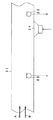
(実施の形態1)図1は本発明の実施の形態1におけるダクト及び能動騒音制御装置の概略図である。本図においてダクト1は流体(空調用又は冷却用の空気)を進行方向Aに搬送(送風)するダクトである。このダクト1の上流には、整流手段として第1の整流網3、整流格子2、第2の整流網4がこの順序で取り付けられている。整流格子2は断面がハニカム形状、円形、又は矩形の形状を有する小孔又は細管がダクトの軸方向(z軸方向)に多数設けられたものであり、搬送流体の速度ベクトルをz軸方向に整える機能を有する。整流格子の一例として、セルサイズが3/16インチ、開口率96%、格子長さ100mmのハニカム材を用いる。
【0025】
第1の整流網3及び第2の整流網4は、所定の開口率を持つ網(例えば、線径0.508mm、目数10/インチ、開口率64%)であり、流体に対して圧力損失を与えることにより、流体の速度をダクト1の垂直面内で均等化する機能を有する。第1の整流網3と第2の整流網4は同じ開口率のものを使用したが、異なる開口率の網を使用しても良い。流体の圧力損失は開口率が小さいほど大きくなる。
【0026】
このような構造のダクト1の上流であって、第2の整流網4の直後に騒音検出マイク5を騒音検出器として取り付け、このダクト1の下流に制御音源7と誤差検出マイク6(誤差検出器)を取り付ける。そして騒音検出マイク5からの参照信号、及び誤差検出マイク6からの残差信号に基づいて、制御信号を生成する演算手段8を設ける。演算手段8は能動騒音制御アルゴリズムを用いて誤差検出マイク6での残差信号が小さくなるように制御信号を生成する。制御音源7は演算手段8の制御信号を制御音に変換して、制御音をダクト1の下流で放射するスピーカである。図中の矢印Aは流体の進行方向を示し、矢印Bは騒音の伝搬方向を示す。
【0027】
このように構成された能動騒音制御装置の動作を説明する。図示しない送風機が動作したとき、送風機自身から騒音が発生したり、送風による風切り音が機器内の部品によって発生する。このようなダクト1内の騒音に対して制御音源7からの制御音を作用させ、その誤差騒音を誤差検出マイク6で検出し、演算手段8に誤差信号を出力する。また、騒音検出マイク5はダクト1内の騒音を検出し、騒音信号として演算手段8に出力する。演算手段8は、LMS(Least Mean Square) アルゴリズム等を用いて、騒音信号と相関のある誤差信号が常に小さくなるような制御信号を生成し、制御音源7に出力する。
【0028】
騒音検出マイク5からダクト1を介して誤差検出マイク6までの伝達関数をGとし、制御音源7から誤差検出マイク6までの伝達関数をCとすると、演算手段8が動作してその伝達関数を−G/Cにすると、誤差検出マイク6の出力がゼロに近づく。騒音検出マイク5における騒音をNとすると、誤差検出マイク6での騒音はN・Gとなる。制御音源7による制御音は誤差検出マイク6の部分で、
N・(−G/C)・C=−N・Gとなる。
誤差検出マイク6の部分では、騒音N・Gと制御音(−N・G)は互いに干渉し、
N・G+(−N・G)=0となる。
従って、誤差検出マイク6を設置した近傍では、騒音と制御音との干渉によって、騒音レベルが低減される。
【0029】
一方、騒音信号と相関の無い誤差信号BNが存在する場合、騒音検出マイク5における騒音は、
N・G+BNとなる。
演算手段8は騒音信号と相関の無い誤差信号を小さくするような制御信号を生成することができない。従って誤差検出マイク6での残留騒音は、
N・G+BN+(−N・G)=BNとなる。
【0030】
騒音信号と誤差信号の相関は一般的にコヒーレンスによって数値化される。図2に示すように、相関関係即ちコヒーレンスγを大きな値にすることによって騒音低減効果も大きくなることが分かる。ダクト1内の騒音において、騒音検出マイク5の騒音信号と、誤差検出マイク6の誤差信号とのコヒーレンスを低下させる原因は、流体の乱流、渦流、旋回流等により発生する圧力変動にある。従って流体を整流することによってコヒーレンスを増加させることができる。
【0031】
図3は整流手段である整流格子や整流網を用いない場合の騒音検出マイク5の騒音信号と誤差検出マイク6の誤差信号とのコヒーレンスを、周波数軸上で示したものである。図4は整流手段として整流格子2(開口率96%、格子長さ40mmのハニカム材)と1枚の整流網(開口率60%)を用いた場合のコヒーレンスを、周波数軸上で示したものである。図5は整流手段である整流格子2(図4で用いたものと同じ)と、図4の実験で用いた1枚の整流網と同等な圧力損失になるように選定した第1の整流網3と第2の整流網4(いずれも開口率72%)を用いた場合のコヒーレンスを示したものである。いずれも内寸100×100mmの矩形ダクトに、ダクト内の平均速度を6m/sで通風した場合の結果である。
【0032】
図3に示すように整流手段を用いない場合は、300Hz以下の周波数帯域ではコヒーレンスが一意的に低下しているのに対し、図4に示すように整流格子と1枚の整流網を用いた場合は、100〜300Hzでコヒーレンスが改善される。これは整流格子と整流網によってダクト内の整流化が行われ、乱流、渦流、旋回流等により発生する騒音が低下したためである。
【0033】
更に図5に示すように、整流手段である整流格子2と第1の整流網3と第2の整流網4を用いると、100〜300Hzでコヒーレンスが更に改善される。
【0034】
図6〜図8に誤差検出マイク6における誤差信号の音圧周波数特性を示す。図6は整流手段を用いない場合の音圧周波数特性、図7は整流格子と1枚の整流網を用いた場合の音圧周波数特性、図8は整流手段である整流格子2と第1の整流網3と第2の整流網4とを用いた場合の音圧周波数特性である。
【0035】
整流手段を用いていない場合の図6に比べ、整流格子と1枚の整流網によってダクト内の整流を行なった場合の図7では、300Hz以下の音圧が低下していることが判る。さらに本発明の整流手段である整流格子2と第1の整流網3と第2の整流網4とを用いた場合の図8では、300Hz以下の音圧が図6、図7に示した結果よりも更に低下していることが判る。この低下分は乱流、渦流、旋回流等により発生する圧力変動と考えられる。このことからも、整流格子2と第1の整流網3と第2の整流網4によって整流化されたことが判る。
【0036】
尚、本実施の形態では、整流格子2として断面がハニカム形状の部材を用いたが、前述したように断面形状はハニカムに限るものではなく、円形や矩形その他の形状を有するものを用いてもよい。また、第1の整流網3と第2の整流網4についても、本実施の形態で用いたもの以外でもよく、流体を整流するための公知の評価基準に基づく選択によるものでよい。また、本実施の形態では第1の整流網3と第2の整流網4は同じ開口率のものを使用したが、異なる開口率の網を使用してもよい。
【0037】
更に本実施の形態では、図1の矢印A及び矢印Bで示したように流体の進行方向と騒音の伝搬方向が同じ場合を示したが、図9に示すように矢印Aの流体の進行方向と矢印Bの騒音の伝搬方向が異なる場合がある。例えば吸気ファンが図9の右側にある場合、流体は同じぐ矢印A方向に流れるが、吸気ファンによる騒音は矢印B方向に伝搬する。そしてこのような冷却装置を有する機器の利用者が、図9の左側に位置する場合、利用者側で騒音が低減される必要がある。このような場合についても、整流部材及び能動騒音制御装置を配設することで、同様な効果が得られることは言うまでもない。
【0038】
以上、本実施の形態に示すように、ダクトの整流手段として整流格子と2枚の整流網を併用することによって、ダクト内の流体を整流化することができる。その結果、騒音検出マイクの騒音信号と誤差検出マイクの誤差信号の相関が高まり、優れた騒音低減効果を有する能動騒音制御装置が実現できる。
【0039】
(実施の形態2)
次に本発明の実施の形態2による能動騒音制御装置について、図面を参照しながら詳細に説明する。図10及び図11は本発明の実施の形態2における能動騒音制御装置の全体構成図である。図12〜図16は本実施の形態の能動騒音制御装置によって得られる騒音検出マイクの騒音信号と誤差検出マイクの誤差信号とのコヒーレンスである。
【0040】
図10において、ダクト1の上流に複数の騒音検出マイク5a,5b・・・5nを取り付け、このダクト1の下流に制御音源7と誤差検出マイク6a,6b・・・6hを取り付ける。騒音検出マイクの個数と誤差検出マイクの個数とは、同じでもよいし、異なってもよい。D1はダクト内を伝搬する音の伝搬方向で互いに最も離れた騒音検出マイク5a〜5n間の距離である。D2はダクト内を伝搬する音の伝搬方向で互いに最も離れた誤差検出マイク6a〜6h間の距離である。
【0041】
そして騒音検出マイク5a,5b・・・5nの参照信号を加算する第1の加算器9を設け、誤差検出マイク6a,6b・・・6hの残差信号を加算する第2の加算器10を設ける。演算手段8は、第1の加算器9の出力と第2の加算器10の出力とに基づいて制御信号を生成するものである。即ち、演算手段8は能動騒音制御アルゴリズムを用いて第2の加算器10の出力が小さくなるように制御信号を生成する。制御音源7は演算手段8の制御信号を制御音に変換して、制御音をダクト1の下流で放射するスピーカである。図中の矢印Aは流体の進行方向を示し、矢印Bは騒音の伝搬方向を示す。
【0042】
このように構成された能動騒音制御装置の動作を説明する。騒音検出マイク5a〜5nはダクト1内の上流側の複数地点での各騒音を検出し、夫々の騒音信号を第1の加算器9に入力する。第1の加算器9はn個の騒音検出マイクの出力信号を加算して演算手段8に出力する。また誤差検出マイク6a,6b・・・6hはダクト1内の下流側の複数地点での各残差信号を検出し、夫々の残差信号を第2の加算器10に入力する。第2の加算器10はh個の誤差検出マイクの残差信号を加算して演算手段8に出力する。
【0043】
演算手段8は、LMS(Least Mean Square) アルゴリズム等により騒音信号と相関のある誤差信号が常に小さくなるような制御信号を生成して制御音源7に出力する。加算器9と加算器10との間における伝達関数、即ち騒音検出マイク5a〜5nからダクト1を介して誤差検出マイク6a〜6hまでの等価伝達関数をGとする。またし、制御音源7から第2の加算器10までの伝達関数、即ち制御音源7から誤差検出マイク6a,6b・・・6hまでの等価伝達関数をCとする。演算手段8が動作して第2の加算器10の出力値がゼロに近づいたとき、演算手段8の伝達関数は−G/Cとなる。従って、第1の加算器9から出力される騒音信号をNとすると、制御音源7の制御音によるダクト1内の値は、
N・(−G/C)・C=−N・Gとなる。
誤差検出マイク6a〜6hを配置した領域で、騒音と制御音とは互いに干渉し、
N・G+(−N・G)=0となる。
従って、誤差検出マイク6a〜6hを設置した領域において、騒音レベルが制御音の干渉によって低減される。
【0044】
一方、騒音信号と相関のない誤差信号BNが存在する場合の誤差信号は、
N・G+BNとなる。
騒音信号と相関のない誤差信号を小さくするような制御信号を演算手段8で生成することがでない。このため、誤差検出マイク6a〜6hの点で騒音と制御音との合成結果は、
N・G+BN+(−N・G)=BNとなる。従って残留騒音はBNとなる。
【0045】
ダクト1内の騒音において、騒音検出マイク5a〜5nの騒音信号と誤差検出マイク6a〜6hの誤差信号とのコヒーレンスを低下させる原因は、前述したように流体の乱流、渦流、旋回流等により発生する圧力変動成分、即ち上式のBNが存在するためである。乱流、渦流、旋回流等による圧力変動は局所的であるため、近接した複数の点でも圧力変動には相関がない。一方、ダクト1内の騒音の各周波数成分のうち、ダクト断面の寸法に比べて長い波長を有する周波数帯域のものは、ダクト1内で平面波として伝搬する。平面波となっている周波数帯域では、騒音の伝搬方向と垂直な面における騒音の音圧と位相は等しくなる。従って、騒音検出マイク5a〜5nと誤差検出マイク6a〜6hとを、夫々の騒音の伝搬方向と垂直な面上に配置した場合、騒音検出マイク5aで検出される騒音信号は次のようになる。即ちダクト1内の騒音信号をN1とし、流体の乱流、渦流、旋回流等により発生する圧力変動成分をBN1とすると、
N1+BN1となる。
【0046】
上記と同様に、騒音検出マイク5nで検出される騒音信号は次のようになる。即ちダクト内の騒音信号をNnとし、流体の乱流、渦流、旋回流等により発生する圧力変動成分をBNnとすると、
Nn+BNnとなる。
【0047】
第1の加算器9では、騒音検出マイク5a〜5nの夫々の騒音信号を加算して出力するから、第1の加算器9の出力は、
(N1+BN1)+(N1+BN2)+…+(Nn+BNn)となる。
【0048】
ここで先に述べたように、平面波となっている周波数帯域では、騒音の伝搬方向と垂直な面の騒音の音圧と位相とは等しくなる。このため平面波のダクト1内の騒音信号はD1=D2=0の場合、
N1=N1=・・・=Nn=Nとなる。よって第1の加算器9の出力は、
n×N+BN1+BN1+…+BNnとなる。
【0049】
上式のBN1+BN2+・・・+BNnは、互いに無相関であるため、n×BNの値よりも小さくなる。このことから第1の加算器9の出力に占める流体の乱流、渦流、旋回流等により発生する圧力変動成分の割合は、複数の騒音検出マイクの出力信号を加算することで低下し、ダクト1内の騒音信号が明確になる。誤差検出マイクについても同様に、複数の誤差検出マイク6a〜6nの出力信号を加算することで、第2の加算器10の出力に占める流体の乱流、渦流、旋回流等により発生する圧力変動成分の割合は低下し、ダクト1内の騒音信号が明確になる。そのため、夫々1つの騒音検出マイク5a〜5nの出力信号と、夫々1つの誤差検出マイク6a〜6hの出力信号とのコヒーレンスに比べて、複数の騒音検出マイクの出力信号を加算する第1の加算器9と、複数の誤差検出マイクの出力信号を加算する第2の加算器10とのコヒーレンスは高い数値を示すことになる。
【0050】
図12は、第1の加算器9には1個の騒音検出マイクの信号を入力し、第2の加算器10にはD2=0cmとして配設した4個の誤差検出マイクの信号を入力した場合、第1の加算器9の出力信号と第2の加算器10の出力信号とのコヒーレンスを示している。
【0051】
図13は、第1の加算器9にはD1=0cmとして配設した4個の騒音検出マイクの信号を入力し、第2の加算器10には1個の誤差検出マイクの信号を入力した場合、第1の加算器9の出力信号と第2の加算器10の出力信号とのコヒーレンスを示している。
【0052】
図14は、第1の加算器9にはD1=0cmとして配設した4個の騒音検出マイクの信号を入力し、第2の加算器10にはD2=0cmとして配設した4個の誤差検出マイクの信号を入力した場合、第1の加算器9の出力信号と第2の加算器10の出力信号とのコヒーレンスを示している。
【0053】
また図15は、第1の加算器9にはD1=10cmとして配設した4個の騒音検出マイクの信号を入力し、第2の加算器10には1個の誤差検出マイクの信号を入力した場合、第1の加算器9の出力信号と第2の加算器10の出力信号とのコヒーレンスを示している。
【0054】
いずれも内寸100×100mmの矩形ダクトにダクト内平均速度6m/sの通風をした場合の結果である。それぞれ図4に示した各々1つの騒音検出マイクと誤差検出マイクの出力信号のコヒーレンスに比べて100〜300Hzでコヒーレンスが改善している。
【0055】
一方、図13に示したD1=0cmとして4個の騒音検出マイクを配設した場合と、図15に示したD1=10cmとして4個の騒音検出マイクを配設した場合のコヒーレンスを比較すると、800Hz以上の周波数帯域では図15に示したコヒーレンスが図13に示すコヒーレンスより低い値を示している。これは、D1=10cmは850Hzの1/4波長(位相角90度)に相当するからである。そして850Hz以上の周波数帯域では、D1=10cmの距離が位相角にして90度以上となるため、複数の騒音検出マイクの出力信号を加算した場合に互いの出力信号を打ち消し合う現象が生じるためである。
【0056】
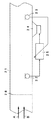
次に図11に示すように整流手段を有するダクト1について考える。このダクト1の上流にには、セルサイズ3/16インチ、開口率96%、格子長さ40mmのハニカム材で構成される整流格子2を配置する。そして整流格子2の前後にいずれも開口率72%の第1の整流網3と第2の整流網4とを配置する。
【0057】
図16は、第1の加算器9にはD1=0として配設した4の騒音検出マイクの信号を入力し、第2の加算器10にはD2=0として配設した4個の誤差検出マイクの信号を入力した場合、第1の加算器9の出力信号と第2の加算器10の出力信号とのコヒーレンスを示している。
【0058】
いずれも内寸100×100mmの矩形ダクトにダクト内平均速度6m/sの通風をした場合の結果である。図4に示した各々1つの騒音検出マイクと誤差検出マイクの出力信号のコヒーレンス、図5に示した整流格子2と2枚の整流網3、4とを使用した場合のコヒーレンス、図14に示したように第1の加算器9にはD1=0cmとして配設した4個の騒音検出マイクの信号を入力し、第2の加算器10にはD2=0cmとして配設した4個の誤差検出マイクの信号を入力して第1の加算器9と第2の加算器10との出力信号間のコヒーレンスと比べて、図16に示す特性では100〜300Hzでコヒーレンスが改善していることが判る。
【0059】
尚、本実施の形態では、整流格子2として断面がハニカム形状の部材を用いたが、断面形状はハニカムに限るものではなく、円形や矩形その他の形状を有する物を用いてもよい。また、第1の整流網3と第2の整流網4についても、流体を整流するための公知の評価基準に基づく物を用いてもよいことは言うまでもない。
【0060】
また、本実施の形態では第1の整流網と第2の整流網は同じ開口率のものを使用したが、異なる開口率の網を使用しても良い。更に、本実施の形態では図10及び図11の矢印A及び矢印Bで示したように、流体の進行方向と騒音の伝搬方向が同じ場合を騒音対象にした。しかし、本実施の形態においても図17又は図18の構成にすることで、流体の進行方向と騒音の伝搬方向が異なる場合についても同様な効果が得られることは言うまでもない。
【0061】
本実施の形態に示すように、整流手段を設けることにより、ダクト内の乱流成分等に起因する圧力変化の影響を低減する。そして、ダクト内騒音を収音する手段として複数の騒音検出マイクを設け、誤差検出マイク又は騒音検出マイクを各々収音したい周波数の1/4波長以下の間隔で配設することによって、ダクト内の騒音を効果的に収音することができる。その結果、騒音検出マイクの騒音信号と誤差検出マイクの誤差信号の相関が高まり、優れた騒音低減効果を有する能動騒音制御装置を実現できる。
【0062】
【発明の効果】
以上、請求項1〜4記載の発明によれば、騒音検出器で検出される騒音信号と誤差検出器の手前で検出される騒音信号の相関が高まり、コヒーレンスを用いて優れた騒音低減効果を有する騒音制御音を生成することができる。
【0063】
さらに請求項1〜4記載の発明によれば、上記の効果に加えて、2つの加算器の出力を用いることにより、流体の圧力変動の影響をより低減することができ、優れた騒音低減効果が得られる。
【0064】
特に請求項1記載の発明によれば、第1、第2の整流網、及び整流格子は、騒音源側から騒音が伝播する方向に第1の整流網、整流格子、第2の整流網の順で配置されており、ダクト内の流体を少ない圧力損失で整流することが可能になる。その結果、騒音検出器の騒音信号と誤差検出器の手前で検出される騒音信号の相関が高まり、より優れた騒音低減効果が得られる。
【図面の簡単な説明】
【図1】本発明の実施の形態1における能動騒音制御装置の構成図である。
【図2】騒音信号と誤差信号とのコヒーレンスにおいて、コヒーレンスと最大低減量との関係を示す特性図である。
【図3】整流対策を施さない場合のダクトにおいて、騒音信号と誤差信号のコヒーレンスの周波数特性図である。
【図4】整流対策(その1)を施した場合のダクトにおいて、騒音信号と誤差信号のコヒーレンスの周波数特性図である。
【図5】整流対策(その2)を施した場合のダクトにおいて、騒音信号と誤差信号のコヒーレンスの周波数特性図である。
【図6】図3の状態での誤差信号の音圧周波数特性である。
【図7】図4の状態での誤差信号の音圧周波数特性である。
【図8】図5の状態での誤差信号の音圧周波数特性である。
【図9】流体の進行方向と騒音の伝搬方向とが異なる場合を前提した実施の形態1の能動騒音制御装置の構成図である。
【図10】本発明の実施の形態2(その1)における能動騒音制御装置の構成図である。
【図11】本発明の実施の形態2(その2)における能動騒音制御装置の構成図である。
【図12】図10に示した能動騒音制御装置において、1個の騒音検出マイクと、D2=0cmとして4個の誤差検出マイクとを配設した場合、第1の加算器と第2の加算器の出力信号間のコヒーレンス周波数特性図である。
【図13】図10に示した能動騒音制御装置において、D1=0cmとして4個の騒音検出マイクと、1個の誤差検出マイクを配設した場合、第1の加算器と第2の加算器の出力信号間のコヒーレンス周波数特性図である。
【図14】図10に示した能動騒音制御装置において、D1=0cmとして4個の騒音検出マイクと、D2=0cmとして4個の誤差検出マイクを配設した場合、第1の加算器と第2の加算器の出力信号間のコヒーレンス周波数特性図である。
【図15】図10に示した能動騒音制御装置において、D1=10cmとして4個の騒音検出マイクと、1個の誤差検出マイクを配設した場合、第1の加算器と第2の加算器の出力信号間のコヒーレンス周波数特性図である。
【図16】図11に示した能動騒音制御装置において、D1=0cmとして4個の騒音検出マイクと、D2=0cmとして4個の誤差検出マイクを配設した場合、第1の加算器と第2の加算器の出力信号間のコヒーレンス周波数特性図である。
【図17】流体の進行方向と騒音の伝搬方向とが異なる場合を前提した実施の形態2(その1)の能動騒音制御装置の構成図である。
【図18】流体の進行方向と騒音の伝搬方向とが異なる場合を前提した実施の形態2(その2)の能動騒音制御装置の構成図である。
【図19】従来例の電子消音を行う能動騒音制御装置の構成図である。
【図20】従来例のアクティブサイレンサの要部構成図である。
【図21】従来例の能動騒音制御装置の構成図である。
【図22】従来例の騒音低減装置の構成図である。
【図23】包囲型エンジンに用いられる従来例の騒音低減装置の構成図である。
【符号の説明】
1 ダクト
2 整流格子
3,4 整流網
5,5a〜5n 騒音検出マイク
6,6a〜6h 誤差検出マイク
7 制御音源
8 演算手段
9,10 加算器[0001]
BACKGROUND OF THE INVENTION
The present invention relates to an active noise control device that reduces noise generated in a fluid duct.
[0002]
[Prior art]
With the integration of today's residential and work environments, noise sources such as air conditioners and office automation equipment and living spaces are often in close proximity. As a result, increasing the distance from the noise source often makes it difficult to attenuate or insulate the noise, or to install the sound absorbing material. Thus, the noise in the living space is increasing, and there is a need for improvement. In OA equipment, a cooling fan and a fluid duct are provided to cool a heat generating part in the equipment, but these exhaust sounds or intake sounds are often annoying.
[0003]
As a general measure for reducing the noise in the duct, there is a method in which a sound absorbing material is attached to the inner wall of the duct and a sound absorbing process is performed. There is also a method to reduce the noise that propagates through the duct by installing a sound reduction muffler and a sound reduction chamber. However, in order to reduce noise with a frequency of 1 kHz or less by these measures, there is a problem that a duct with a large volume is required.
[0004]
On the other hand, there is a concept of active noise control as a technique for reducing noise in a low frequency band without increasing the duct volume, which is applied to an air conditioning duct. For example, there are methods disclosed in Japanese Patent Laid-Open Nos. 61-296392 and 62-1156. In this method, as shown in FIG. 19, there is a
[0005]
There is also a method disclosed in Japanese Patent Laid-Open No. 62-206212. In this method, as shown in FIG. 20, there is a
[0006]
As a result, at the position of the error detection microphone 23, a control sound having the same sound pressure as that of the noise propagating in the
[0007]
FIG. 2 shows the relationship between the coherence (γ) between the noise detection microphone and the error detection microphone and the maximum noise reduction amount (predictive reduction effect R) by active noise control. When the coherence is 0.8 or more, the maximum noise reduction amount greatly increases. As shown in FIG. 2, in order to obtain a sufficient noise reduction effect by active noise control, a high value of coherence is required, but the coherence value decreases due to the occurrence of turbulence or vortex flow in the duct. . That is, the noise detection microphone and the error detection microphone detect not only the pressure fluctuation caused by noise but also the pressure fluctuation caused by turbulent flow or eddy current, and the coherence value between the two microphones decreases.
[0008]
As a technique for solving this problem, a technique for improving coherence by rectification in a duct is proposed in Japanese Patent Laid-Open No. 5-188976. For example, as shown in FIG. 21, there is a
[0009]
Further, there is a method disclosed in JP-A-9-89356. In this method, as shown in FIG. 22, there is a
[0010]
Further, there are methods disclosed in JP-A-10-39877 and JP-A-10-39878. In these methods, as shown in FIG. 23, the bent portion of the
[0011]
[Problems to be solved by the invention]
However, the active noise control device for the duct having the above structure has the following problems. That is, since the duct is curved for miniaturization, or a plurality of ducts merge or branch, the shape of the duct becomes complicated. For this reason, if the duct has a simple configuration, the air for air conditioning is rectified by the above-described conventional countermeasures, and active noise control is performed using the coherence between the noise detection microphone and the error detection microphone. Can be obtained. However, in the case of a duct having a complicated shape, sufficient active noise control cannot be performed by the above-described conventional countermeasures.
[0012]
The present invention has been made in view of the above-described conventional problems, and achieves a sufficient noise reduction effect using coherence even for a duct having a complicated shape without increasing the size of the apparatus. An object is to realize an active noise control device.
[0013]
[Means for Solving the Problems]
The invention of
[0017]
The invention according to
[0022]
Claims of the
[0023]
Claims of the
[0024]
DETAILED DESCRIPTION OF THE INVENTION
Hereinafter, an active noise control apparatus according to an embodiment of the present invention will be described in detail with reference to the drawings.
(Embodiment 1) FIG. 1 is a schematic diagram of a duct and an active noise control apparatus according to
[0025]
The
[0026]
A
[0027]
The operation of the active noise control apparatus configured as described above will be described. When a blower (not shown) is operated, noise is generated from the blower itself, or wind noise caused by blown air is generated by components in the device. The control sound from the control sound
[0028]
If the transfer function from the
N · (−G / C) · C = −N · G.
In the
N · G + (− N · G) = 0.
Therefore, in the vicinity where the
[0029]
On the other hand, when there is an error signal BN uncorrelated with the noise signal, the noise in the
N · G + BN.
The calculation means 8 cannot generate a control signal that reduces the error signal that has no correlation with the noise signal. Therefore, the residual noise in the
N · G + BN + (− N · G) = BN.
[0030]
The correlation between the noise signal and the error signal is generally quantified by coherence. As shown in FIG. 2, it can be seen that the noise reduction effect is increased by increasing the correlation, that is, the coherence γ. In the noise in the
[0031]
FIG. 3 shows the coherence between the noise signal of the
[0032]
When the rectifying means is not used as shown in FIG. 3, the coherence is uniquely reduced in the frequency band of 300 Hz or lower, whereas the rectifying grid and one rectifying network are used as shown in FIG. In the case, coherence is improved at 100 to 300 Hz. This is because rectification in the duct is performed by the rectifying grid and the rectifying network, and noise generated by turbulent flow, vortex flow, swirl flow, and the like is reduced.
[0033]
Further, as shown in FIG. 5, when the
[0034]
6 to 8 show the sound pressure frequency characteristics of the error signal in the
[0035]
It can be seen that the sound pressure at 300 Hz or lower is reduced in FIG. 7 in the case where the rectification in the duct is performed by the rectifying grid and one rectifying network, compared to FIG. 6 in the case where the rectifying means is not used. Furthermore, in the case of using the
[0036]
In the present embodiment, a member having a honeycomb shape in cross section is used as the
[0037]
Further, in the present embodiment, as shown by the arrows A and B in FIG. 1, the fluid traveling direction and the noise propagation direction are the same. However, as shown in FIG. And the arrow B may have different noise propagation directions. For example, when the intake fan is on the right side of FIG. 9, the fluid flows in the same arrow A direction, but noise from the intake fan propagates in the arrow B direction. And when the user of the apparatus which has such a cooling device is located in the left side of FIG. 9, a noise needs to be reduced by the user side. In such a case, it goes without saying that the same effect can be obtained by arranging the rectifying member and the active noise control device.
[0038]
As described above, the fluid in the duct can be rectified by using the rectifying grid and the two rectifying networks in combination as the rectifying means for the duct, as shown in the present embodiment. As a result, the correlation between the noise signal of the noise detection microphone and the error signal of the error detection microphone is increased, and an active noise control device having an excellent noise reduction effect can be realized.
[0039]
(Embodiment 2)
Next, an active noise control apparatus according to
[0040]
10, a plurality of noise detection microphones 5a, 5b... 5n are attached upstream of the
[0041]
A
[0042]
The operation of the active noise control apparatus configured as described above will be described. The noise detection microphones 5 a to 5 n detect noises at a plurality of points on the upstream side in the
[0043]
The calculation means 8 generates a control signal such that an error signal correlated with the noise signal is always small by an LMS (Least Mean Square) algorithm or the like and outputs the control signal to the control sound
N · (−G / C) · C = −N · G.
In the area where the error detection microphones 6a to 6h are arranged, the noise and the control sound interfere with each other,
N · G + (− N · G) = 0.
Therefore, in the area where the error detection microphones 6a to 6h are installed, the noise level is reduced by the interference of the control sound.
[0044]
On the other hand, the error signal when there is an error signal BN that has no correlation with the noise signal is
N · G + BN.
A control signal that reduces an error signal that has no correlation with the noise signal is not generated by the calculation means 8. For this reason, the synthesis result of the noise and the control sound at the point of the error detection microphones 6a to 6h is
N · G + BN + (− N · G) = BN. Therefore, the residual noise is BN.
[0045]
In the noise in the
N1 + BN1.
[0046]
Similarly to the above, the noise signal detected by the noise detection microphone 5n is as follows. That is, if the noise signal in the duct is Nn, and the pressure fluctuation component generated by fluid turbulence, vortex flow, swirl flow, etc. is BNn,
Nn + BNn.
[0047]
Since the
(N1 + BN1) + (N1 + BN2) +... + (Nn + BNn).
[0048]
Here, as described above, in the frequency band that is a plane wave, the sound pressure and phase of the noise in the plane perpendicular to the noise propagation direction are equal. Therefore, the noise signal in the
N1 = N1 =... = Nn = N. Therefore, the output of the
n × N + BN1 + BN1 +... + BNn.
[0049]
Since BN1 + BN2 +... + BNn in the above formula are uncorrelated with each other, they are smaller than the value of n × BN. Therefore, the ratio of the pressure fluctuation component generated by the turbulent flow, vortex flow, swirl flow, etc. of the fluid in the output of the
[0050]
In FIG. 12, the signal of one noise detection microphone is input to the
[0051]
In FIG. 13, signals from four noise detection microphones arranged as D1 = 0 cm are input to the
[0052]
In FIG. 14, the signals of four noise detection microphones arranged as D1 = 0 cm are inputted to the
[0053]
In FIG. 15, signals from four noise detection microphones arranged with D1 = 10 cm are input to the
[0054]
Both Inside dimension It is a result at the time of ventilating the average speed in a duct 6m / s to a rectangular duct of 100x100mm. The coherence is improved at 100 to 300 Hz as compared with the coherence of the output signals of each one noise detection microphone and error detection microphone shown in FIG.
[0055]
On the other hand, comparing the coherence between the case where four noise detection microphones are arranged with D1 = 0 cm shown in FIG. 13 and the case where four noise detection microphones are arranged with D1 = 10 cm shown in FIG. In the frequency band of 800 Hz or higher, the coherence shown in FIG. 15 is lower than the coherence shown in FIG. This is because D1 = 10 cm corresponds to a quarter wavelength of 850 Hz (phase angle 90 degrees). In the frequency band of 850 Hz or more, the distance of D1 = 10 cm is 90 degrees or more in phase angle, and therefore, when the output signals of a plurality of noise detection microphones are added, a phenomenon occurs in which the output signals cancel each other. is there.
[0056]
Next, consider a
[0057]
In FIG. 16, the
[0058]
Both Inside dimension It is a result at the time of ventilating the average speed in a duct 6m / s to a rectangular duct of 100x100mm. The coherence of the output signal of each one noise detection microphone and error detection microphone shown in FIG. 4, the coherence when the
[0059]
In the present embodiment, a honeycomb-shaped member is used as the
[0060]
In this embodiment, the first rectification network and the second rectification network have the same aperture ratio, but networks having different aperture ratios may be used. Further, in the present embodiment, as indicated by arrows A and B in FIGS. 10 and 11, the case where the fluid traveling direction and the noise propagation direction are the same is targeted. However, it goes without saying that the same effect can be obtained even in the case where the fluid traveling direction and the noise propagation direction are different by adopting the configuration of FIG. 17 or 18 in the present embodiment.
[0061]
As shown in the present embodiment, by providing the rectifying means, the influence of the pressure change caused by the turbulent flow component in the duct is reduced. A plurality of noise detection microphones are provided as means for collecting the noise in the duct, and the error detection microphones or the noise detection microphones are disposed at intervals of 1/4 wavelength or less of the frequency at which the sound is desired to be collected. Noise can be collected effectively. As a result, the correlation between the noise signal of the noise detection microphone and the error signal of the error detection microphone is increased, and an active noise control device having an excellent noise reduction effect can be realized.
[0062]
【The invention's effect】
As described above, claims 1 to 4 According to the described invention, the correlation between the noise signal detected by the noise detector and the noise signal detected before the error detector is increased, and noise control sound having an excellent noise reduction effect is generated using coherence. be able to.
[0063]
Further claims 1 to 4 According to the described invention, in addition to the above-described effect, by using the outputs of the two adders, the influence of the fluid pressure fluctuation can be further reduced, and an excellent noise reduction effect can be obtained.
[0064]
Especially claims 1 According to the described invention, The first and second rectification networks and the rectification grid are arranged in the order of the first rectification network, the rectification grid, and the second rectification network in the direction in which noise propagates from the noise source side, It becomes possible to rectify the fluid in the duct with a small pressure loss. As a result, the correlation between the noise signal of the noise detector and the noise signal detected before the error detector is increased, and a more excellent noise reduction effect can be obtained.
[Brief description of the drawings]
FIG. 1 is a configuration diagram of an active noise control apparatus according to
FIG. 2 is a characteristic diagram showing a relationship between coherence and a maximum reduction amount in coherence between a noise signal and an error signal.
FIG. 3 is a frequency characteristic diagram of coherence between a noise signal and an error signal in a duct when rectification measures are not taken.
FIG. 4 is a frequency characteristic diagram of coherence between a noise signal and an error signal in a duct when a rectification measure (part 1) is taken.
FIG. 5 is a frequency characteristic diagram of coherence between a noise signal and an error signal in a duct when a rectification measure (part 2) is taken.
6 is a sound pressure frequency characteristic of an error signal in the state of FIG.
7 is a sound pressure frequency characteristic of an error signal in the state of FIG.
8 is a sound pressure frequency characteristic of an error signal in the state of FIG.
FIG. 9 is a configuration diagram of the active noise control apparatus according to the first embodiment on the assumption that the fluid traveling direction and the noise propagation direction are different.
FIG. 10 is a configuration diagram of an active noise control apparatus according to Embodiment 2 (Part 1) of the present invention.
FIG. 11 is a configuration diagram of an active noise control apparatus according to Embodiment 2 (part 2) of the present invention.
12 shows a case where one noise detection microphone and four error detection microphones with D2 = 0 cm are arranged in the active noise control apparatus shown in FIG. 10, and the first adder and the second addition are performed. It is a coherence frequency characteristic figure between the output signals of a device.
13 shows a case where four noise detection microphones and one error detection microphone are arranged with D1 = 0 cm in the active noise control apparatus shown in FIG. 10, and a first adder and a second adder are provided. It is a coherence frequency characteristic figure between output signals.
14 shows a case where four active noise control microphones with D1 = 0 cm and four error detection microphones with D2 = 0 cm are arranged in the active noise control apparatus shown in FIG. It is a coherence frequency characteristic figure between the output signals of 2 adders.
15 shows a case where four noise detection microphones and one error detection microphone are arranged with D1 = 10 cm in the active noise control apparatus shown in FIG. 10, and a first adder and a second adder are provided. It is a coherence frequency characteristic figure between output signals.
FIG. 16 shows the active noise control apparatus shown in FIG. 11, in which four noise detection microphones with D1 = 0 cm and four error detection microphones with D2 = 0 cm are arranged with the first adder and the first adder. It is a coherence frequency characteristic figure between the output signals of 2 adders.
FIG. 17 is a configuration diagram of the active noise control apparatus according to the second embodiment (part 1) on the assumption that the fluid traveling direction and the noise propagation direction are different.
FIG. 18 is a configuration diagram of an active noise control apparatus according to a second embodiment (part 2) on the assumption that the fluid traveling direction and the noise propagation direction are different.
FIG. 19 is a configuration diagram of an active noise control apparatus that performs electronic silencing according to a conventional example.
FIG. 20 is a main part configuration diagram of a conventional active silencer.
FIG. 21 is a configuration diagram of a conventional active noise control apparatus.
FIG. 22 is a configuration diagram of a conventional noise reduction device.
FIG. 23 is a configuration diagram of a conventional noise reduction device used for a surrounding engine.
[Explanation of symbols]
1 Duct
2 Rectifier grid
3, 4 Rectifier network
5,5a ~ 5n Noise detection microphone
6, 6a-6h Error detection microphone
7 Control sound source
8 Calculation means
9,10 adder
Claims (4)
前記誤差検出器よりも騒音源側において、互いに近接した状態で配設され、騒音源から伝播するダクト内の騒音を検出する複数の騒音検出器と、
前記複数の誤差検出器の誤差信号を加算する第1の加算器と、
前記複数の騒音検出器の騒音信号を加算する第2の加算器と、
前記複数の誤差検出器の近傍に設置され、前記騒音と略同音圧かつ逆位相の制御音を放射する制御音源と、
前記第1の加算器の出力信号と前記第2の加算器の出力信号とを入力し、前記第1の加算器の信号が小さくなるように伝達関数を設定し、前記第2の加算器の出力信号を前記伝達関数で乗算し、乗算結果を制御信号として前記制御音源に出力する演算手段と、
ダクト内において、前記複数の騒音検出器と、騒音源との間に配設され、ダクト内の流体を整流化する整流手段と、を具備し、
前記ダクトの断面の内寸は、騒音源から伝播してくる騒音の波長の長さよりも小さく、
前記整流手段は、第1、第2の整流網、及び細管の集合体である整流格子を有し、
前記第1、第2の整流網、及び前記整流格子は、騒音源側から騒音が伝播する方向に前記第1の整流網、前記整流格子、前記第2の整流網の順で配置されており、
前記複数の誤差検出器は、近接する誤差検出器との間隔を、打ち消すべき騒音の波長の略1/4以下の範囲内とし、
前記複数の騒音検出器は、近接する騒音検出器との間隔を、打ち消すべき騒音の波長の略1/4以下の範囲内としたことを特徴とする能動騒音制御装置。A plurality of error detectors that are arranged in close proximity to each other and detect noise in the duct propagating from the noise source;
A plurality of noise detectors that are arranged closer to each other on the noise source side than the error detector and detect noise in the duct propagating from the noise source,
A first adder for adding error signals of the plurality of error detectors;
A second adder for adding the noise signals of the plurality of noise detectors;
A control sound source that is installed in the vicinity of the plurality of error detectors and emits a control sound having substantially the same sound pressure and opposite phase as the noise;
The output signal of the first adder and the output signal of the second adder are input, a transfer function is set so that the signal of the first adder becomes small, and the second adder An arithmetic means for multiplying an output signal by the transfer function and outputting a multiplication result to the control sound source as a control signal;
In the duct, comprising a plurality of noise detectors and a rectifying means disposed between the noise sources and rectifying the fluid in the duct,
The inner dimension of the cross section of the duct is smaller than the length of the wavelength of the noise propagating from the noise source,
The rectifying means has first and second rectifying networks and a rectifying grid which is an aggregate of thin tubes.
The first and second rectification networks and the rectification grid are arranged in the order of the first rectification network, the rectification grid, and the second rectification network in a direction in which noise propagates from a noise source side. ,
The plurality of error detectors have an interval between adjacent error detectors within a range of approximately ¼ or less of a wavelength of noise to be canceled,
The active noise control apparatus characterized in that the plurality of noise detectors have an interval between adjacent noise detectors within a range of about 1/4 or less of a wavelength of noise to be canceled.
前記整流格子は前記第1、第2の整流網より開口率が大きいことを特徴とする請求項1に記載の能動騒音制御装置。In the rectifying means,
The active noise control device according to claim 1, wherein the rectifying grid has a larger aperture ratio than the first and second rectifying networks.
ダクト内を伝搬する音の伝搬方向と垂直な平面上に配置したことを特徴とする請求項1または2に記載の能動騒音制御装置。The plurality of noise detectors are:
The active noise control device according to claim 1, wherein the active noise control device is arranged on a plane perpendicular to a propagation direction of sound propagating in the duct.
ダクト内を伝搬する音の伝搬方向と垂直な平面上に配置したことを特徴とする請求項1〜3のいずれか1項記載の能動騒音制御装置。The plurality of error detectors are:
The active noise control device according to any one of claims 1 to 3, wherein the active noise control device is arranged on a plane perpendicular to a propagation direction of sound propagating in the duct.
Priority Applications (3)
| Application Number | Priority Date | Filing Date | Title |
|---|---|---|---|
| JP2000381490A JP4409755B2 (en) | 2000-12-15 | 2000-12-15 | Active noise control device |
| EP01128925.3A EP1223572B1 (en) | 2000-12-15 | 2001-12-05 | Active noise control system |
| US10/007,674 US7158644B2 (en) | 2000-12-15 | 2001-12-10 | Active noise control system |
Applications Claiming Priority (1)
| Application Number | Priority Date | Filing Date | Title |
|---|---|---|---|
| JP2000381490A JP4409755B2 (en) | 2000-12-15 | 2000-12-15 | Active noise control device |
Publications (3)
| Publication Number | Publication Date |
|---|---|
| JP2002186085A JP2002186085A (en) | 2002-06-28 |
| JP2002186085A5 JP2002186085A5 (en) | 2007-12-20 |
| JP4409755B2 true JP4409755B2 (en) | 2010-02-03 |
Family
ID=18849473
Family Applications (1)
| Application Number | Title | Priority Date | Filing Date |
|---|---|---|---|
| JP2000381490A Expired - Lifetime JP4409755B2 (en) | 2000-12-15 | 2000-12-15 | Active noise control device |
Country Status (3)
| Country | Link |
|---|---|
| US (1) | US7158644B2 (en) |
| EP (1) | EP1223572B1 (en) |
| JP (1) | JP4409755B2 (en) |
Families Citing this family (17)
| Publication number | Priority date | Publication date | Assignee | Title |
|---|---|---|---|---|
| US7853024B2 (en) * | 1997-08-14 | 2010-12-14 | Silentium Ltd. | Active noise control system and method |
| IL121555A (en) * | 1997-08-14 | 2008-07-08 | Silentium Ltd | Active acoustic noise reduction system |
| KR100730358B1 (en) * | 2003-09-08 | 2007-06-20 | 샤프 가부시키가이샤 | Ion diffusing apparatus |
| WO2008090544A2 (en) * | 2007-01-22 | 2008-07-31 | Silentium Ltd. | Quiet fan incorporating active noise control (anc) |
| JP4790843B2 (en) * | 2007-03-30 | 2011-10-12 | 富士通株式会社 | Active silencer and active silencer method |
| US20100002385A1 (en) * | 2008-07-03 | 2010-01-07 | Geoff Lyon | Electronic device having active noise control and a port ending with curved lips |
| US8165311B2 (en) * | 2009-04-06 | 2012-04-24 | International Business Machines Corporation | Airflow optimization and noise reduction in computer systems |
| JP6182524B2 (en) | 2011-05-11 | 2017-08-16 | シレンティウム リミテッド | Noise control devices, systems, and methods |
| US9928824B2 (en) | 2011-05-11 | 2018-03-27 | Silentium Ltd. | Apparatus, system and method of controlling noise within a noise-controlled volume |
| JP2015079028A (en) * | 2012-02-03 | 2015-04-23 | 三菱電機株式会社 | Active noise control device |
| US9286882B1 (en) | 2012-03-07 | 2016-03-15 | Great Lakes Sound & Vibration, Inc. | Systems and methods for active exhaust noise cancellation |
| US10061332B2 (en) * | 2014-07-14 | 2018-08-28 | Dell Products, Lp | Active acoustic control of cooling fan and method therefor |
| CN106469551A (en) * | 2015-08-19 | 2017-03-01 | 中兴通讯股份有限公司 | A kind of pipeline noise reduction system and method |
| DE102017200822A1 (en) * | 2017-01-19 | 2018-07-19 | Bayerische Motoren Werke Aktiengesellschaft | Ventilation device for an interior of a motor vehicle and method for operating such a ventilation device |
| JP6880848B2 (en) * | 2017-03-10 | 2021-06-02 | 富士通株式会社 | Microwave irradiation equipment, exhaust gas purification equipment, automobiles and management systems |
| WO2020080040A1 (en) * | 2018-10-19 | 2020-04-23 | 富士フイルム株式会社 | Soundproofing system |
| CN113998142B (en) * | 2021-11-16 | 2024-03-08 | 中国商用飞机有限责任公司 | Noise reproduction system and method for aircraft cabin air conditioning pipeline |
Family Cites Families (19)
| Publication number | Priority date | Publication date | Assignee | Title |
|---|---|---|---|---|
| US3821999A (en) * | 1972-09-05 | 1974-07-02 | Mc Donnell Douglas Corp | Acoustic liner |
| JPS61296392A (en) | 1985-06-26 | 1986-12-27 | 日立プラント建設株式会社 | Electronic silencing system |
| JPS621156A (en) | 1985-06-26 | 1987-01-07 | Hitachi Plant Eng & Constr Co Ltd | Electronic noise eliminating system |
| JPS62206212A (en) | 1986-03-05 | 1987-09-10 | Mitsubishi Heavy Ind Ltd | Active silencer |
| US5175401A (en) * | 1991-03-18 | 1992-12-29 | Grumman Aerospace Corporation | Segmented resistance acoustic attenuating liner |
| US5216722A (en) * | 1991-11-15 | 1993-06-01 | Nelson Industries, Inc. | Multi-channel active attenuation system with error signal inputs |
| JPH05188976A (en) | 1992-01-16 | 1993-07-30 | Toshiba Corp | Active noise controller |
| EP0552400A1 (en) * | 1992-01-24 | 1993-07-28 | Eldim, Inc. | Sound absorbing corrugated structural material |
| JP3340496B2 (en) * | 1993-03-09 | 2002-11-05 | 富士通株式会社 | Estimation method of transfer characteristics of active noise control system |
| GB2279778B (en) * | 1993-05-19 | 1997-06-04 | Samsung Electronics Co Ltd | Vacuum cleaner |
| US5689572A (en) * | 1993-12-08 | 1997-11-18 | Hitachi, Ltd. | Method of actively controlling noise, and apparatus thereof |
| US5606622A (en) * | 1994-09-29 | 1997-02-25 | The Boeing Company | Active noise control in a duct with highly turbulent airflow |
| US6201872B1 (en) * | 1995-03-12 | 2001-03-13 | Hersh Acoustical Engineering, Inc. | Active control source cancellation and active control Helmholtz resonator absorption of axial fan rotor-stator interaction noise |
| JPH11509008A (en) * | 1995-07-05 | 1999-08-03 | アルマックス インコーポレイテッド | Active noise control method and apparatus for duct high order mode |
| JPH0989356A (en) | 1995-09-25 | 1997-04-04 | Fujitsu Ltd | Noise reducing method |
| FR2740599B1 (en) * | 1995-10-30 | 1997-12-19 | Technofirst | ACTIVE ACOUSTIC MITIGATION DEVICE INTENDED TO BE ARRANGED WITHIN A DUCT, PARTICULARLY FOR SOUNDPROOFING A VENTILATION AND / OR AIR CONDITIONING NETWORK |
| JPH1039877A (en) | 1996-07-24 | 1998-02-13 | Kubota Corp | Noise reducing device of enclosed engine |
| JPH1039878A (en) | 1996-07-24 | 1998-02-13 | Kubota Corp | Noise reduction device of enclosed engine |
| US6782109B2 (en) * | 2000-04-04 | 2004-08-24 | University Of Florida | Electromechanical acoustic liner |
-
2000
- 2000-12-15 JP JP2000381490A patent/JP4409755B2/en not_active Expired - Lifetime
-
2001
- 2001-12-05 EP EP01128925.3A patent/EP1223572B1/en not_active Expired - Lifetime
- 2001-12-10 US US10/007,674 patent/US7158644B2/en active Active
Also Published As
| Publication number | Publication date |
|---|---|
| EP1223572A2 (en) | 2002-07-17 |
| EP1223572B1 (en) | 2013-05-01 |
| JP2002186085A (en) | 2002-06-28 |
| US7158644B2 (en) | 2007-01-02 |
| EP1223572A3 (en) | 2007-09-26 |
| US20020080978A1 (en) | 2002-06-27 |
Similar Documents
| Publication | Publication Date | Title |
|---|---|---|
| JP4409755B2 (en) | Active noise control device | |
| JP5615360B2 (en) | Air conditioner | |
| JP5923690B2 (en) | Range food | |
| JP2012002370A (en) | Indoor unit for air conditioner, and air conditioner | |
| JPH07162979A (en) | Microphone fitting structure | |
| JP6007416B2 (en) | Ventilation equipment | |
| JPH05119784A (en) | Active muffler | |
| JP3507522B2 (en) | Active silencer | |
| JPH1039878A (en) | Noise reduction device of enclosed engine | |
| JP6248285B2 (en) | Range food | |
| JP3511582B2 (en) | Active noise control device | |
| JP2005037447A (en) | Noise controller of air conditioner | |
| JP6191005B2 (en) | Ventilation fan | |
| JP2014228759A (en) | Active silencer | |
| JP2885861B2 (en) | Active control silencer | |
| JP3446242B2 (en) | Active silencer | |
| JP3634406B2 (en) | Active silencer | |
| JP3466654B2 (en) | Active silencer | |
| JP2011107673A (en) | Method for determining position of noise detection means in silencing system | |
| JP2014157013A (en) | Air conditioner | |
| JPH1039877A (en) | Noise reducing device of enclosed engine | |
| JP6229153B2 (en) | Blower with active silencer | |
| JPH0989356A (en) | Noise reducing method | |
| JP2005164706A (en) | Device for reducing noise inside duct | |
| JPH07253788A (en) | Active noise reducing device |
Legal Events
| Date | Code | Title | Description |
|---|---|---|---|
| A521 | Written amendment |
Free format text: JAPANESE INTERMEDIATE CODE: A523 Effective date: 20071106 |
|
| A621 | Written request for application examination |
Free format text: JAPANESE INTERMEDIATE CODE: A621 Effective date: 20071106 |
|
| A977 | Report on retrieval |
Free format text: JAPANESE INTERMEDIATE CODE: A971007 Effective date: 20090408 |
|
| A131 | Notification of reasons for refusal |
Free format text: JAPANESE INTERMEDIATE CODE: A131 Effective date: 20090414 |
|
| A521 | Written amendment |
Free format text: JAPANESE INTERMEDIATE CODE: A523 Effective date: 20090610 |
|
| A131 | Notification of reasons for refusal |
Free format text: JAPANESE INTERMEDIATE CODE: A131 Effective date: 20090714 |
|
| A521 | Written amendment |
Free format text: JAPANESE INTERMEDIATE CODE: A523 Effective date: 20090910 |
|
| TRDD | Decision of grant or rejection written | ||
| A01 | Written decision to grant a patent or to grant a registration (utility model) |
Free format text: JAPANESE INTERMEDIATE CODE: A01 Effective date: 20091020 |
|
| A01 | Written decision to grant a patent or to grant a registration (utility model) |
Free format text: JAPANESE INTERMEDIATE CODE: A01 |
|
| A61 | First payment of annual fees (during grant procedure) |
Free format text: JAPANESE INTERMEDIATE CODE: A61 Effective date: 20091112 |
|
| R150 | Certificate of patent or registration of utility model |
Free format text: JAPANESE INTERMEDIATE CODE: R150 Ref document number: 4409755 Country of ref document: JP Free format text: JAPANESE INTERMEDIATE CODE: R150 |
|
| FPAY | Renewal fee payment (event date is renewal date of database) |
Free format text: PAYMENT UNTIL: 20121120 Year of fee payment: 3 |
|
| FPAY | Renewal fee payment (event date is renewal date of database) |
Free format text: PAYMENT UNTIL: 20121120 Year of fee payment: 3 |
|
| FPAY | Renewal fee payment (event date is renewal date of database) |
Free format text: PAYMENT UNTIL: 20131120 Year of fee payment: 4 |
|
| EXPY | Cancellation because of completion of term |