WO2011155609A1 - Procédé de fabrication d'un corps constitué d'un alliage d'aluminium (al) - Google Patents
Procédé de fabrication d'un corps constitué d'un alliage d'aluminium (al) Download PDFInfo
- Publication number
- WO2011155609A1 WO2011155609A1 PCT/JP2011/063406 JP2011063406W WO2011155609A1 WO 2011155609 A1 WO2011155609 A1 WO 2011155609A1 JP 2011063406 W JP2011063406 W JP 2011063406W WO 2011155609 A1 WO2011155609 A1 WO 2011155609A1
- Authority
- WO
- WIPO (PCT)
- Prior art keywords
- alloy
- mass
- treatment
- aging
- zone
- Prior art date
Links
Images


Classifications
-
- C—CHEMISTRY; METALLURGY
- C22—METALLURGY; FERROUS OR NON-FERROUS ALLOYS; TREATMENT OF ALLOYS OR NON-FERROUS METALS
- C22C—ALLOYS
- C22C21/00—Alloys based on aluminium
- C22C21/10—Alloys based on aluminium with zinc as the next major constituent
-
- B—PERFORMING OPERATIONS; TRANSPORTING
- B21—MECHANICAL METAL-WORKING WITHOUT ESSENTIALLY REMOVING MATERIAL; PUNCHING METAL
- B21J—FORGING; HAMMERING; PRESSING METAL; RIVETING; FORGE FURNACES
- B21J1/00—Preparing metal stock or similar ancillary operations prior, during or post forging, e.g. heating or cooling
-
- B—PERFORMING OPERATIONS; TRANSPORTING
- B22—CASTING; POWDER METALLURGY
- B22D—CASTING OF METALS; CASTING OF OTHER SUBSTANCES BY THE SAME PROCESSES OR DEVICES
- B22D11/00—Continuous casting of metals, i.e. casting in indefinite lengths
- B22D11/001—Continuous casting of metals, i.e. casting in indefinite lengths of specific alloys
- B22D11/003—Aluminium alloys
-
- B—PERFORMING OPERATIONS; TRANSPORTING
- B22—CASTING; POWDER METALLURGY
- B22D—CASTING OF METALS; CASTING OF OTHER SUBSTANCES BY THE SAME PROCESSES OR DEVICES
- B22D11/00—Continuous casting of metals, i.e. casting in indefinite lengths
- B22D11/12—Accessories for subsequent treating or working cast stock in situ
- B22D11/1213—Accessories for subsequent treating or working cast stock in situ for heating or insulating strands
-
- B—PERFORMING OPERATIONS; TRANSPORTING
- B32—LAYERED PRODUCTS
- B32B—LAYERED PRODUCTS, i.e. PRODUCTS BUILT-UP OF STRATA OF FLAT OR NON-FLAT, e.g. CELLULAR OR HONEYCOMB, FORM
- B32B15/00—Layered products comprising a layer of metal
- B32B15/01—Layered products comprising a layer of metal all layers being exclusively metallic
- B32B15/016—Layered products comprising a layer of metal all layers being exclusively metallic all layers being formed of aluminium or aluminium alloys
-
- C—CHEMISTRY; METALLURGY
- C22—METALLURGY; FERROUS OR NON-FERROUS ALLOYS; TREATMENT OF ALLOYS OR NON-FERROUS METALS
- C22F—CHANGING THE PHYSICAL STRUCTURE OF NON-FERROUS METALS AND NON-FERROUS ALLOYS
- C22F1/00—Changing the physical structure of non-ferrous metals or alloys by heat treatment or by hot or cold working
- C22F1/04—Changing the physical structure of non-ferrous metals or alloys by heat treatment or by hot or cold working of aluminium or alloys based thereon
- C22F1/053—Changing the physical structure of non-ferrous metals or alloys by heat treatment or by hot or cold working of aluminium or alloys based thereon of alloys with zinc as the next major constituent
-
- A—HUMAN NECESSITIES
- A63—SPORTS; GAMES; AMUSEMENTS
- A63B—APPARATUS FOR PHYSICAL TRAINING, GYMNASTICS, SWIMMING, CLIMBING, OR FENCING; BALL GAMES; TRAINING EQUIPMENT
- A63B2209/00—Characteristics of used materials
-
- B—PERFORMING OPERATIONS; TRANSPORTING
- B23—MACHINE TOOLS; METAL-WORKING NOT OTHERWISE PROVIDED FOR
- B23K—SOLDERING OR UNSOLDERING; WELDING; CLADDING OR PLATING BY SOLDERING OR WELDING; CUTTING BY APPLYING HEAT LOCALLY, e.g. FLAME CUTTING; WORKING BY LASER BEAM
- B23K2103/00—Materials to be soldered, welded or cut
- B23K2103/08—Non-ferrous metals or alloys
- B23K2103/10—Aluminium or alloys thereof
Definitions
- the present invention relates to a method for manufacturing an Al alloy joined body in which an Al (aluminum) alloy is joined by welding, and a related technique.
- Al-Zn-Mg Al alloys are often used as structural materials because of their excellent strength and workability.
- Patent Documents 1 to 3 in order to secure sufficient strength in conventional Al—Zn—Mg alloys, complex heat treatment is required for a long time as an aging treatment. There is a problem that it is difficult to improve the performance. Further, when trying to simplify the heat treatment, there is a problem that sufficient strength cannot be obtained, reinforcement by thickening or the like is required, and it is difficult to reduce the weight.
- the present invention has been made in view of the above problems, and an object of the present invention is to provide an Al alloy joined body manufacturing method and related technology capable of efficiently producing a high-strength and lightweight Al alloy joined body.
- the present invention has the following configuration.
- an Al alloy ingot having a structure of 40 ⁇ m or less and a crystallite having an average particle size of 8 ⁇ m or less;
- For the Al alloy cast member performing hot forging to obtain an Al alloy forged member;
- the casting speed is a speed at which the ingot is pulled from the mold, and is obtained by measuring the moving speed of the ingot per unit time. At the time of casting, the speed is gradually increased from the stopped state, and the maximum speed is reached when the casting is stable. In the present invention, this maximum speed is referred to as the maximum casting speed.
- the one-stage aging treatment refers to an aging treatment once (once) in a relatively short time.
- the one-stage aging process of the present invention is a single aging process, and is different from the two-stage aging process in which the first-stage aging process and the second-stage aging process are performed twice.
- the one-step aging treatment of the present invention is a relatively short time, and is different from a one-step aging treatment in which a complicated one-step aging treatment is performed for a long time, for example, a complicated temperature control is performed for a long time of 24 hours or more.
- the room temperature treatment may be performed, or after the solution treatment, the one-step aging treatment is performed immediately without performing the room temperature treatment. You may make it do.
- An apparatus for manufacturing an Al alloy joined body characterized by the above.
- a water tank zone further comprising a quenching water tank in which water is stored between the solution heat treatment zone and the one-stage aging heat treatment zone, After performing the solution treatment, before performing the one-stage aging treatment, the material to be treated is passed through the water tank of the water tank zone and the quenching process is performed. Manufacturing equipment.
- the solution heat treatment zone and the one-stage aging heat treatment zone are arranged in parallel, and the conveying direction of the material to be treated is opposite to each other,
- the carry-out side end of the solution heat treatment zone and the carry-in side end of the one-stage aging heat treatment zone are arranged correspondingly, 9.
- a step based on the step of obtaining the Al alloy ingot and a step based on the step of obtaining the Al alloy cast member were sequentially performed.
- the actual characteristics obtained from the prototype Al alloy forged member are compared with the target characteristics, and based on the comparison result, the fourth preparation step of changing the temporary value, 11.
- the method for producing an Al alloy cast member according to item 10 wherein the third and fourth preparation steps are repeatedly performed to prepare an Al alloy molten metal to be actually used.
- an Al alloy ingot having a structure of 40 ⁇ m or less and a crystallite having an average particle size of 8 ⁇ m or less;
- a step of obtaining an Al alloy cast member by subjecting the Al alloy ingot to a homogenization treatment for holding at a temperature of 400 to 600 ° C. for 1 hour or more;
- For the Al alloy cast member performing hot forging to obtain an Al alloy forged member;
- a step of subjecting the Al alloy forged member after solution treatment to a one-step aging treatment are examples of the Al alloy cast member after solution treatment.
- a step based on the step of obtaining the Al alloy ingot, a step based on the step of obtaining the Al alloy cast member, and the Al alloy forging are sequentially performed to obtain a prototype Al alloy forged member.
- a target aging time in the temporary aging treatment is set in advance
- the actual aging time is measured
- the actual aging time is compared with the target aging time, and the temporary value is changed based on the comparison result. Manufacturing method.
- a plurality of joined parts made of an Al alloy are welded, and a welded portion is provided at a welded portion between the joined parts, and heat that is affected by heat in the vicinity of the welded portion is exerted.
- An Al alloy joined body provided with an affected part Among the plurality of joined parts, at least one joined part is Fe: 0.2 to 0.35 mass%, Cu: 0.1 to 0.4 mass%, Mn: 0.3 to 0.6 Wt%, Mg: 2.0-2.5 wt%, Zn: 5.0-5.5 wt%, Zr: 0.1-0.2 wt%, Ti: 0.2 wt% or less,
- the balance has an alloy composition consisting of Al and inevitable impurities, The relationship of “V 1 / V 2 ⁇ 0.8” is established, where the hardness of the heat affected zone is “V 1 ” and the average hardness of the portion not affected by the heat caused by welding is “V 2 ”.
- an Al alloy forged product having high strength, desired mechanical characteristics and corrosion resistance performance can be obtained without losing hardness recovery performance after welding. Can do. Moreover, since the one-step aging treatment can be simplified in a short time, an Al alloy joined body having the desired characteristics can be efficiently produced.
- the load that can be withstood in the entire area of the Al alloy joined body is increased, the weight of the Al alloy joined body can be reduced, and the weight can be reduced.
- hardness recovery performance after welding refers to the decrease rate of the Vickers hardness of the heat-affected zone by welding with respect to the Vickers hardness of the base material subjected to T6 treatment, specifically, When the decrease rate is 20% or less, it is judged that the hardness recovery performance after welding is good.
- hardness recovery performance after welding can be defined by the following relational expression.
- Hardness recovery performance after welding (“Vickers hardness of base material”-"Vickers hardness of heat affected zone”) / "Vickers hardness of base material” Further, in the present invention, a material having a tensile strength of 450 MPa or more is determined as “high strength”.
- the Vickers hardness is based on JIS Z 2244. Furthermore, the tensile strength conforms to JIS Z 2201 and JIS Z 2241.
- the aging treatment can be reliably performed and the production efficiency can be more reliably improved.
- an Al alloy joined body having the desired characteristics can be produced more efficiently.
- an Al alloy cast member optimum as an Al alloy joint part for welding can be produced.
- a desired Al alloy molten metal can be prepared and a high quality Al alloy cast member can be obtained.
- an Al alloy forged member for welding according to the invention [12] an Al alloy forged member optimum as an Al alloy joined part for welding can be produced.
- FIG. 1 is a flowchart for explaining a method of manufacturing an Al alloy joined body according to an embodiment of the present invention.
- FIG. 2 is a graph showing the relationship between the maximum casting speed and DSA in an Al alloy.
- FIG. 3 is a perspective view showing a disk sample for alloy composition analysis.
- FIG. 4A is a cross-sectional view showing a state immediately before welding joined parts made of Al alloy.
- FIG. 4B is a cross-sectional view showing a state immediately after the welded parts made of Al alloy are welded together.
- FIG. 5 is a graph showing the relationship between DAS and aging time.
- FIG. 6 is a graph showing the relationship between the average particle size of the crystallization part and the elongation.
- FIG. 7 is a block diagram showing an example of an apparatus for manufacturing an Al alloy joined body according to the present invention.
- FIG. 8 is a block diagram showing another example of an apparatus for manufacturing an Al alloy joined body according to the present invention.
- FIG. 1 is a flowchart for explaining an example of a method for producing an Al alloy joined body according to an embodiment of the present invention.
- an Al alloy molten metal having a predetermined alloy composition is prepared, and an Al alloy ingot is obtained by continuously casting the Al alloy molten metal under predetermined conditions. Subsequently, the Al alloy ingot is homogenized to obtain an Al alloy cast member. Thereafter, hot forging is performed on the Al alloy cast member to obtain an Al alloy forged member. Further, the Al alloy forged member is subjected to a solution treatment and then subjected to a one-stage aging treatment. Then, without performing the aging treatment (second-stage aging treatment), the Al alloy forged members obtained by joining and integrating the Al alloy forged members after the first-stage aging treatment by welding treatment to form the Al alloy product of the present embodiment Is what you get.
- the molten Al alloy as an Al casting material used in the present invention is 0.2 to 0.35 mass% Fe, 0.1 to 0.4 mass% Cu, and 0.3 to 0.6 mass% Mn.
- Mg 2.0 to 2.5 mass%, Zn 5.0 to 5.5 mass%, Zr 0.1 to 0.2 mass%, Ti 0.2 mass% or less, the balance being It has an alloy composition consisting of Al and inevitable impurities.
- Fe is an element that suppresses ingot cracking during casting and weld cracking during welding and suppresses coarse recrystallization.
- the Fe content (concentration) is It is necessary to adjust to 0.2 to 0.35 mass%.
- the Fe content is adjusted to 0.30 to 0.35 mass%.
- Cu not only increases the degree of supersaturation of the solute in the solid solution by dissolving in the aluminum matrix, but also coexists with Mg, thereby precipitating an Al—Cu—Mg intermetallic compound to impart strength. It is.
- Cu coexists with Mg, and the coexistence state with Mg is controlled so that the precipitation state of the Al—Cu—Mg intermetallic compound by aging treatment in the Al alloy becomes fine and dense.
- the behavior of the precipitation can be changed appropriately.
- Cu is a conventional two-stage aging treatment in which the second aging is performed at 140 to 190 ° C. for 2 to 24 hours after the first aging treatment at 80 to 130 ° C. for 1 to 16 hours.
- the relatively short time is, for example, 8 to 12 hours, preferably about 8 hours.
- the mechanism is estimated as follows.
- the Mg—Zn intermetallic compound is coarsely precipitated in the Al matrix at the initial stage of aging.
- the precipitation density becomes coarse, and the precipitation density remains rough even if the aging treatment is continued thereafter. For this reason, the aging effect is not sufficiently obtained, and the maximum value of the hardness is lowered. Therefore, in the past, the size at which the initial temperature of aging is lowered and the Mg—Zn-based intermetallic compound is finely precipitated in the Al matrix and then contributes to the increase in hardness by high-temperature aging treatment or long-term low-temperature aging treatment. The maximum value of hardness is raised by growing precipitates.
- a two-stage aging treatment of a low temperature short time and a high temperature short time or a one-step aging treatment of a low temperature and a long time must be used. Therefore, conventionally, this aging treatment requires a lot of time and complicated temperature control, which has been a factor in reducing productivity.
- the Al—Cu—Mg intermetallic compound can be finely and densely precipitated in the Al matrix at the initial stage of aging, and then Zn—Mg The intermetallic compound is deposited on the finely precipitated Al—Cu—Mg intermetallic compound.
- Zn—Mg-based intermetallic compounds grown to a size that contributes to strength are finely and densely present in the Al matrix, and the maximum value of hardness can be sufficiently increased.
- the Cu content (concentration) it is necessary to adjust the Cu content (concentration) to 0.1 to 0.4 mass%, more preferably 0.30 to 0.40 mass%.
- the Cu content is less than 0.1% by mass, the above effect cannot be obtained sufficiently, and the amount of the Al—Cu—Mg intermetallic compound generated at the early stage of aging is too small.
- the one-stage aging treatment is not desirable because the strength improvement effect cannot be obtained with certainty and a two-stage aging treatment is required.
- the Cu content exceeds 0.4% by mass, the strength is improved, but the stress corrosion cracking resistance is remarkably lowered and there is a risk of generating weld cracks, which is not desirable.
- Mn is an element that suppresses coarse recrystallization.
- it is necessary to adjust the Mn content (concentration) to 0.3 to 0.6% by mass, and preferably to 0.5 to 0.6% by mass.
- the Mn content is less than 0.3% by mass, the effect of suppressing coarse recrystallization is reduced.
- the Mn content exceeds 0.6% by mass, the Al—Fe—Mn-based coarse crystallized product increases, which impairs the plastic workability during forging.
- the processed Al alloy product is finally assembled to a vehicle body or the like, the ductility, toughness, and fatigue strength of the Al alloy product (assembled part) may be reduced.
- Mg is an element that precipitates MgZn 2 intermetallic compound ( ⁇ phase) and improves mechanical strength by coexisting with Zn. Furthermore, as described above, Mg can appropriately change the precipitation behavior of the Al—Cu—Mg intermetallic compound in the early stage of aging by coexisting with Cu. Therefore, Mg is subjected to the second stage aging treatment, which is conventionally performed at 80 to 130 ° C. for 1 to 16 hours and then the second stage aging treatment at 140 to 190 ° C. for 2 to 24 hours. In order to make it possible to obtain the same mechanical properties and anti-corrosion performance obtained by the treatment by performing a single aging treatment (one-step aging treatment) at 130 to 170 ° C. for a relatively short time. It is a necessary element.
- the relatively short time is, for example, 8 to 12 hours, preferably about 8 hours.
- the Mg content concentration
- 2.2 to 2.5% concentration of the Mg content
- the amount is too large, stress corrosion cracking resistance and quenching sensitivity are lowered, which is not desirable.
- Zn is an element that precipitates MgZn 2 intermetallic compound ( ⁇ phase) and improves mechanical strength by coexisting with Mg.
- the Zn content (concentration) it is necessary to adjust the Zn content (concentration) to 5.0 to 5.5% by mass, and more preferably to 5.2 to 5.5% by mass.
- the precipitation state of the Al—Cu—Mg intermetallic compound in which fine precipitation is progressing means that the Al—Cu—Mg intermetallic compound is in a state where the Al—Cu—Mg intermetallic compound is aligned with the parent phase.
- the state is formed in a rod shape in the 100> direction.
- the state in which the Al—Cu—Mg intermetallic compound is aligned with the parent phase means that the atoms forming the parent phase and the atoms of the Al—Cu—Mg intermetallic compound forming the precipitate are in a one-to-one relationship. It is in a state where it is formed with lattice point correspondence.
- (B-3) “The state in which a finely precipitated Al—Cu—Mg intermetallic compound is used as a nucleus and a Zn—Mg intermetallic compound is deposited thereon” means a Zn—Mg intermetallic compound. Is deposited on the surface of the Al—Cu—Mg intermetallic compound deposited in (b-2) above, and the crystallized product is not sheared by dislocations in the crystallized product that is moved by plastic working or the like. This is the state where the crystallized material has grown to form particles inconsistent with the parent phase.
- mismatched refers to a state in which the atoms forming the parent phase and the atoms of the Zn—Mg intermetallic compound forming the precipitate do not have a one-to-one lattice point correspondence.
- the amount of Cu required for fine precipitation of the Al—Cu—Mg intermetallic compound is 0.1 to 0.4 mass% in the present invention.
- the Al—Zn—Mg intermetallic compound is precipitated without excess and deficiency, the amount of unnecessary crystallized matter is reduced, and the decrease in elongation, which is one of the mechanical properties of the alloy, is suppressed.
- a preferred ratio is 3: 1.
- Ti is an element that promotes refinement of crystal grains at the time of casting.
- TiB 2 is generated, and refinement is particularly promoted. Therefore, it is desirable to add Ti: B at a ratio of 5: 1 in the Al alloy of the present invention.
- TiB 2 is a very hard particle, it promotes wear of the tool during machining. In the present invention, the amount of Ti needs to be adjusted to 0.2% by mass or less.
- Zr is an element that suppresses coarse recrystallization and promotes refinement of crystal grains in the welded portion.
- the content (concentration) of Zr is set to 0.1 to 0.2% by mass. It needs to be adjusted.
- the concentration of Zr is less than 0.1% by mass, it is difficult to sufficiently obtain the above effect.
- the Zr concentration exceeds 0.2% by mass, it reacts with B of TiB 2 added for crystal grain refinement at the time of casting to produce ZrB 2 and inhibit the crystal grain refinement. Resulting in. For this reason, it becomes necessary to add a TiB 2 in large quantities.
- TiB 2 and ZrB 2 are hard particles, when cutting a forged member after forging, the tool life at the time of cutting is shortened. Not desirable. Therefore, the amount (concentration) of Zr needs to be adjusted to 0.1 to 0.2% by mass as described above.
- the addition amount of Ti it is more preferable to set the addition amount of Ti to 0.03 to 0.05 mass% and the addition amount of Zr to 0.10 to 0.15 mass%.
- an Al alloy ingot is obtained by continuously casting a molten Al alloy having the above alloy composition.
- the desired composition (proper value of composition) of the molten Al alloy having the above composition can be obtained by the following design procedure (steps S1 to S9).
- Step S1 (first preparation process: initial value setting)
- the initial value (temporary value) of the manufacturing conditions in the Al alloy molten metal scheduled to be used (scheduled for use) in the production method of the present invention is appropriately set within the range satisfying the conditions of the present invention.
- Fe 0.28 mass%
- Cu 0.25 mass%
- Mn 0.45 mass%
- Mg 2.25 mass%
- Zn 5.25 mass%
- Zr 0.15 mass%
- Ti 0.03% by mass
- ⁇ 3.5
- initial values (temporary values) of the casting diameter and the casting speed are set to, for example, 50 mm and 380 mm / min, respectively.
- this step S1 constitutes a first preparation step.
- Step S2 (second preparation step: target value setting)
- a target characteristic and a target aging time are set for the Al alloy forged member after aging to be manufactured.
- the characteristics include hardness, tensile strength, 0.2% proof stress, elongation, stress corrosion cracking characteristics, hardness recovery after welding, corrosion resistance, and the like, and are set according to specifications from customers, for example. Details of each characteristic are described in Examples and the like to be described in detail later.
- the aging time is an aging treatment time until the hardness after aging reaches a maximum value, and is set to 6 hours, for example.
- this step S2 constitutes a second preparation step.
- Step S3 (third preparation process: prototype production)
- a prototype Al alloy forged member (prototype) according to the present invention is manufactured using a prototype Al alloy melt obtained based on the initial values (prototype manufacturing process).
- the process conforming to the process of obtaining the Al alloy ingot of the present invention, the process conforming to the process of obtaining the Al alloy cast member, and the process of obtaining the Al alloy forged member of the present invention And a step conforming to the step of applying the solution treatment of the present invention, and a step conforming to the step of performing the one-step aging treatment of the present invention in order, a prototype Al alloy forged member (prototype) To manufacture.
- the actual characteristics and actual aging time of the prototype are measured. The characteristics and aging time are as described above.
- this step S3 comprises the 3rd preparation process.
- Step S4 Zn amount adjustment
- Zn is added within the range satisfying the conditions of the present invention. (Increase), and if you want to improve the elongation and stress corrosion cracking properties, decrease (decrease) and change (reset) the temporary value (initial value) of Zn.
- the plus width and minus width are set to 0.1% by mass, for example.
- the step of changing the temporary value of Zn constitutes the fourth preparation step.
- step S4 and step S3 are repeated until the difference between the actually measured value and the target value is within 5%, for example.
- the Zn content is adjusted to an appropriate value.
- Step S5 Mg amount adjustment
- Mg is within the range that satisfies the conditions of the present invention. If you want to improve the elongation and stress corrosion cracking characteristics, change it and change (reset) the temporary value (initial value) of Mg.
- the plus width and minus width are set to 0.1% by mass, for example.
- the step of changing the temporary value of Mg constitutes the fourth preparation step.
- step S5 and step S3 are repeated until the difference between the actually measured value and the target value is within 5%, for example.
- the Mg content is adjusted to an appropriate value.
- Step S6 Cu amount adjustment
- the temporary value of Cu is changed by adding and subtracting to increase elongation, stress corrosion cracking property, and hardness recovery after welding.
- the plus width and minus width are set to 0.1% by mass, for example.
- the step of changing the temporary value of Cu constitutes the fourth preparation step.
- step S6 and step S3 are repeated until the difference between the actually measured value and the target value is within 5%, for example.
- the Cu content is adjusted to an appropriate value.
- Step S7 Adjustment of correction value ⁇
- ⁇ should be within the range satisfying the conditions of the present invention. Plus, if you want to shorten the aging time, decrement and change the temporary value of ⁇ .
- the plus width and minus width are, for example, ⁇ ⁇ 0.1.
- Step S4 and Step S3 are repeated until the difference between the actual measurement value and the target value is within 5%, for example. In this way, ⁇ is adjusted to an appropriate value.
- Step S8 Adjustment of Mn and Zr amounts
- Mn is set according to the conditions of the present invention. Add a value within the range to satisfy, and if you want to improve the plastic workability during forging and improve the dimensional accuracy of a molded product with a complex shape, change the temporary value of Mn.
- the plus width and minus width are set to 0.1% by mass, for example.
- the step of changing the temporary value of Mn constitutes the fourth preparation step.
- this step S8 and the above step S3 are repeated until a desired characteristic is obtained.
- the content of Mn is adjusted to an appropriate value.
- Zr is added within the range that satisfies the conditions of the present invention to improve the plastic workability during forging. If it is desired to improve the dimensional accuracy of a molded product having a complicated shape, the temporary value of Zr is changed.
- the plus width and minus width are set to 0.1% by mass, for example.
- the step of changing the temporary value of Zr is included in the configuration of the fourth preparation step as necessary.
- this step S8 and the above step S3 are repeated until a desired characteristic is obtained.
- the Zr content is adjusted to an appropriate value.
- Step S9 Fe amount adjustment
- Fe is used as the condition of the present invention. If you want to improve the corrosion resistance by adding within the range to be satisfied, change the temporary value of Fe to minus.
- the plus width and minus width are set to 0.1% by weight, for example.
- the step of changing the temporary value of Fe constitutes the fourth preparation step.
- step S9 and step S3 are repeated until a desired characteristic is obtained.
- the Fe content is adjusted to an appropriate value.
- the alloy composition can be determined by the above steps S1 to S9. Alternatively, all the alloy components can be adjusted together, but steps S4 to S7 can be preferentially executed simultaneously.
- the temporary value of Ti may be changed by subtracting it.
- the plus width and minus width are set to 0.1% by weight, for example.
- a conventionally known continuous casting method can be used as the continuous casting method.
- a casting method such as a hot top vertical continuous casting method, a gas pressure type hot top vertical continuous casting method, a horizontal continuous casting method, or the like can be used.
- a gas pressure hot top casting machine it is particularly preferable to use a gas pressure hot top casting machine.
- the alloy composition of the present invention must satisfy the condition of “[maximum casting speed (mm / min)] ⁇ ⁇ 1.43 ⁇ [casting diameter (mm)] + 500” during continuous casting.
- the lower limit of the casting speed presented by the casting plan is preferably 200 mm / min or more from the viewpoint of preventing surface defects of the ingot.
- the casting speed and the maximum casting speed are as described above in the section [Means for Solving the Problems].
- the above-mentioned Al alloy ingot needs to adjust the dendrite secondary arm interval (DAS) to 40 ⁇ m or less.
- DAS dendrite secondary arm interval
- the DAS needs to be 40 ⁇ m or less, preferably 35 ⁇ m or less, more preferably 20 ⁇ m or less.
- Table 1 shows the relationship between maximum casting speed and DAS. As can be seen from Table 1, there is a close relationship between the maximum casting speed and the DAS, and it is possible to control the size of the DAS based on the maximum casting speed.
- FIG. 2 is a graph showing the relationship between the maximum casting speed and DAS.
- ⁇ indicates that the DAS is 40 ⁇ m or less
- X indicates that the DAS exceeds 40 ⁇ m.
- [Maximum casting speed (mm / min)] ⁇ 1.43 ⁇ [Casting diameter (mm)] + 500 as a boundary, DAS is 40 ⁇ m or less on the lower side, 40 ⁇ m on the upper side And satisfying the relationship of “[maximum casting speed (mm / min)] ⁇ ⁇ 1.43 ⁇ [casting diameter (mm)] + 500”, as described above, The size can be suppressed to 40 ⁇ m or less.
- the DAS measurement is performed by “Light Metal (1988), Vol. 38, no. 1, p45 ”is performed according to the“ Dendrite Arm Spacing Measurement Method ”.
- the average particle size of the crystallized product it is necessary to adjust the average particle size of the crystallized product to 8 ⁇ m or less, preferably 1 ⁇ m or more. That is, if the average particle size of the crystallized material is 8 ⁇ m or less, the plastic workability at the time of forging becomes good, so that the occurrence of forging cracks can be suppressed. Furthermore, since the ductility, toughness, and fatigue strength of the forged product are also improved, the occurrence of forging cracks can be suppressed.
- the average particle diameter can be obtained by a section method from an image obtained by observing the crystal structure with a microscope by a conventional method, for example, the following procedure.
- a microphotograph of a cross-sectional structure of a forged product is taken at a magnification of 100 times, and a straight line having vertical and horizontal lengths L1 and L2 is arbitrarily drawn on the photograph.
- the number of grain boundaries existing in the form of intersecting the straight lines of the lengths L1 and L2 was counted as n1 and n2, respectively, and the average grain size was determined by the following formula 1, and this was obtained from the microphotograph.
- the average particle size of the grains is used. The average particle size can be determined without depending on the lengths of L1 and L2.
- the crystallized product is an Al-Si based crystallized product, an Al-Fe-Mn based crystallized product, or an Al-Cu-Mg based crystallized product that is granular or flakes at the grain boundary. Say what crystallized.
- the above-mentioned Al alloy ingot is homogenized to obtain an Al alloy cast member (Al alloy cast member for welding).
- the homogenization treatment is a treatment for holding at a temperature of 400 to 600 ° C., preferably 430 to 500 ° C. for 1 hour or more, preferably about 7 hours.
- the homogenization treatment temperature is too low, the diffusion rate of elements such as Mg, Zn, Cu, which are solute atoms, is slowed down, so that microsegregation of solute elements in the final solidified portion remains, There is a risk of hindering plastic workability during forging. Further, when the treatment time is less than 1 hour, the time required for diffusion of the solute atoms cannot be secured, and there is a possibility that the same adverse effect as when the treatment temperature is low may occur. Moreover, when processing temperature is higher than 600 degreeC, there exists a possibility that an ingot may melt locally, and it is unpreferable.
- the precipitation of the Zr intermetallic compound effective for suppressing recrystallization proceeds simultaneously in parallel.
- Precipitation of the Zr intermetallic compound proceeds even at a temperature lower than 400 ° C. (preferably lower than 430 ° C.), but a long-time treatment is required and it is not suitable for a one-step aging treatment. Therefore, in the homogenization treatment, it is desirable to adjust the treatment temperature to 430 to 500 ° C.
- the Al alloy cast member of the present invention obtained as described above can be suitably used because it can reduce the forging load as a forging material, and further has excellent plastic workability and excellent formability during forging. It is what
- an Al alloy forged member is manufactured by hot forging using the Al alloy cast member as a forging material at a material temperature (preheating temperature) of 350 to 500 ° C.
- the material temperature is preferably set to 460 ° C. or lower.
- the cast member used as the forging material is subjected to machining (for example, cutting or surface cutting) before being put into the forging die, or plastic processing (for example, upsetting) as necessary. It is customary.
- the forging process may be performed a plurality of times.
- the material temperature at the time of hot forging is lower than 350 ° C.
- the plastic workability at the time of forging deteriorates, and a forged product having a desired shape cannot be obtained.
- Cause cracking When the temperature during hot forging is higher than 500 ° C., eutectic melting of the Al—Zn—Mg—Cu-based crystallized material occurs at the surface, resulting in hole defects near the surface of the forged product. Or there is a risk of aggregation of a metal having a low melting point in the surface layer. Therefore, in the present invention, it is desirable to adjust the temperature condition during hot forging to 350 to 500 ° C.
- the Al alloy forged member obtained as described above is subjected to a heat treatment as a solution treatment at 400 to 500 ° C. (preferably 460 ° C.), thereby further improving the mechanical strength of the forged member.
- a heat treatment as a solution treatment at 400 to 500 ° C. (preferably 460 ° C.)
- the forged member is held at 400 to 500 ° C. for 2 to 8 hours, and then poured into water at 25 to 80 ° C. and rapidly cooled.
- a heat-treated Al alloy forged member (Al alloy forged member for welding) is obtained by subjecting an Al alloy forged member subjected to solution treatment to a heat treatment as a one-step aging treatment.
- the apparatus used for the one-stage aging heat treatment has a short temperature rise time as much as possible and has a small temperature error at 100 to 300 ° C., for example, can be controlled within ⁇ 3 ° C.
- a hot air circulation type electric furnace, a hot air circulation type gas furnace, and the like can be exemplified.
- the temperature is raised from room temperature (about 25 ° C.) to 150 ° C. at 150 ° C./hour, and then 130 to 170 ° C., preferably 150 ⁇ 5 ° C., for 8 to 12 hours, preferably 10 ⁇ 0. Hold for 5 hours, and then decrease the temperature from 150 ° C. to room temperature (25 ° C.) at 30 to 300 ° C./hour.
- the heating time is short. That is, the heat treatment time is shortened, the variation in characteristics due to the heat treatment time is reduced, and the production efficiency is increased.
- the one-stage aging treatment sets the temperature condition to 130 to 170 ° C., and the required time is 1 to 6 times the solution treatment time. It is good to set. That is, the one-step aging treatment is preferably performed under the conditions of 130 to 170 ° C. ⁇ [solution treatment time ⁇ (1 to 6)].
- the time of leaving the substrate at room temperature does not particularly affect the characteristics of the Al alloy forged member. This is because the Al—Cu—Mg based precipitate is deposited first even at room temperature. Therefore, the time for leaving the solution at room temperature after the solution treatment can be freely set according to the setup of the product production process. For example, immediately after the solution treatment, the one-stage aging treatment may be performed, or after the solution treatment, the first-stage aging treatment may be performed after being left at room temperature for a long time or an appropriate time. Also good. As a result, the degree of freedom in designing the manufacturing process conditions is increased, which is preferable.
- FIG. 5 is a graph showing the relationship between DAS and aging time in aging treatment (one-stage aging treatment).
- the aging time means the time until the hardness after aging becomes maximum, as described above.
- the aging time in the graph is shown as a relative value when the aging time of a sample having a DAS of 33 ⁇ m is 100.
- the aging temperature is set to 160 ° C., and the average particle size of the crystallized product is adjusted to 7 ⁇ m.
- the aging time is shortened. That is, in this invention, since DAS is adjusted to 40 micrometers or less, an aging time can be shortened and production efficiency can be improved.
- the reason for this is that when the DAS is small as in the present invention, the amount of solute atoms diffused through the grain boundary is large, and the diffusion rate of solute atoms during precipitation is increased even when a one-step aging treatment is performed. . As a result, the aging time is shortened.
- the value of DAS can be controlled by the cooling rate of the ingot. That is, when the cooling rate is high, the DAS is reduced, and when the cooling rate is reduced, the DAS is increased.
- base data 1 to 4 For reference, the specific numerical data (base data 1 to 4) that form the basis of Fig. 5 is shown below.
- the aging time is shown as a relative value with a reference value of 100 as described above.
- the average particle size of the crystallized product is all adjusted to 7 ⁇ m.
- FIG. 6 is a graph showing the relationship between the average grain size of the crystallized product and the elongation after aging treatment (after one-stage aging treatment).
- the elongation is measured after solution treatment at 460 ° C. ⁇ 4 Hr, water quenching treatment at a water temperature of 65 ° C., and aging treatment at 160 ° C. ⁇ 8 Hr.
- this elongation is shown as a relative value when the elongation of a sample having an average particle size of the crystallized substance of 12.4 ⁇ m is defined as 100.
- the DAS is adjusted to 35 ⁇ m.
- the average particle size of the crystallized material is 8 ⁇ m or less
- the elongation is large.
- the average particle size of the crystallized product is adjusted to 8 ⁇ m or less, a forged member having a large elongation and excellent mechanical properties can be obtained.
- base data 11 to 14 as the basis of FIG. 6 are shown below.
- the elongation is shown as a relative value when the reference value is 100 as described above. All DAS are adjusted to 35 ⁇ m.
- the graphs of FIGS. 5 and 6 are obtained by adjusting the size of DAS and crystallized matter by changing the casting diameter and casting speed based on Table 1 and FIG. 2 in Example 1 described later. is there.
- the heat-treated Al alloy forged member subjected to heat treatment such as solution treatment and one-step aging treatment is a high-strength Al alloy joint obtained by welding and integrating a plurality of Al alloy joint parts. It can employ
- an Al alloy forged member 11 according to the present invention is welded to an Al alloy-made joining component (another joining component) 12 prepared in the other way, thereby producing an Al alloy as shown in FIG. 4B.
- the joined body (Al alloy welded structure) 10 is assembled.
- the other joining parts 12 to be joined may be made of an Al alloy with a reduced amount of hydrogen gas, and may be joining parts made of an Al alloy having the same composition.
- the other joining parts 12 include those made of a heat-treated Al alloy forged member according to the present invention, those made of an Al extruded material obtained by extruding the aforementioned Al alloy cast member, and the aforementioned Al alloy molten metal.
- the thing which consists of obtained Al casting, the thing which consists of aluminum die-cast products, etc. can be mentioned.
- the welding method used in the present invention is not particularly limited, and a known method can be used.
- a welding method such as TIG welding or MIG welding can be suitably used.
- various methods such as a butt joint, a corner joint, a T joint, and a lap joint can be used as a method for butting the joint surfaces.
- the addition amount of Cu is suppressed to 0.1 to 0.4 mass%, so that the quenching sensitivity is insensitive. Accordingly, after the temperature of the Al alloy forged member rises to a high temperature during welding, it is naturally cooled only by being cooled naturally, and is then left to stand for natural aging, thereby increasing the hardness. For this reason, since it has excellent hardness recovery performance after welding and has sufficient strength, as shown in FIG. 4A, the Al alloy forged member is abutted and welded as joining parts 11 and 12, and FIG. As shown in FIG. 5, when the Al alloy joined body 10 is manufactured, sufficient hardness can be secured.
- the one-stage aging of the present invention can be applied, and the hardness difference between the heat-influenced portion and the heat-affected zone is small because of the one-step aging treatment of the present invention. Become. As a result, the hardness recovery performance of the entire member as the Al alloy joined body is improved.
- the build-up portion 14 in the welded portion 13 has a large cross-sectional area even if the hardness is reduced due to the adverse effect of welding heat. For this reason, the load resistance is large and there is no problem such as breakage.
- the heat-affected zone 15 in the vicinity of the build-up portion 14 has no change in cross-sectional area and has a small cross-sectional area. Therefore, when it is annealed by welding heat, the hardness is lowered, and problems such as fracture occur.
- the Al alloy forged members (joint parts) 11 and 12 of the present invention are excellent in the hardness recovery performance after welding, the heat-affected zone 15 sufficiently recovers the hardness after welding and is desired. The strength of the can be ensured.
- the hardness of the heat-affected zone 15 in the Al alloy welded body 15 is a ratio of 0.8 or more with respect to the average hardness of the other portion 16 that is not affected by welding, and sufficient hardness is obtained. Can be secured.
- V 1 the hardness of the heat affected zone 15
- V 2 the hardness of the other portion 16 having no heat influence
- the Al alloy joined body (Al alloy product) obtained by the production method of the present invention is Fe: 0.2 to 0.35 mass%, Cu: 0.1 to 0.4 mass%, Mn: 0.3 ⁇ 0.6 mass%, Mg: 2.0-2.5 mass%, Zn: 5.0-5.5 mass%, Zr: 0.1-0.2 mass%, Ti: 0.2 mass% It has the alloy composition which contains below and the remainder consists of Al and an unavoidable impurity, and the hardness of the heat affected zone 15 becomes a ratio of 0.8 or more with respect to the average hardness of the part 16 which does not have the influence of heat by welding. ing.
- the portions that are not adversely affected by the heat caused by welding do not cause a decrease in hardness due to the welding heat, so that sufficient strength can be maintained.
- the Al alloy joined body obtained by the production method of the present invention can be suitably used as a part for a high-strength Al alloy welded structure.
- Examples of components for this high-strength weld structure include golf club beds, motorcycle fuel tanks, motorcycle frames, motorcycle swing arms, four-wheeled vehicle sub-frames, four-wheeled vehicle bumper beams, and four-wheeled vehicle steering. Examples include parts used for column shafts and railcar structures.
- the conventional forged member made of Al—Zn—Mg alloy disclosed in Patent Document 2 Japanese Patent Laid-Open No. 57-158360
- the time required for a general solution treatment is about 2 to 8 hours. Therefore, in order to continuously perform the solution treatment and the aging treatment, it is necessary to balance the time between the solution treatment and the aging treatment. For example, it is necessary to install an aging treatment furnace for aging treatment that requires a long time as many as five times the solution treatment furnace for solution treatment that can be processed in a short time, which not only increases the equipment introduction cost, This will increase the size of the equipment. Further, it is complicated to make a production plan, and the production efficiency is lowered.
- the aging treatment time can be 12 hours at the longest, and can be adjusted to a time that does not greatly differ from the solution treatment time.
- solution treatment and aging treatment can be performed continuously within 20 hours with such a compact and compact equipment, so that production lead time can be shortened and product inventory can be reduced. Furthermore, since the combined time of the solution treatment and the aging treatment can be within 20 hours, for example, the solution treatment and the aging treatment are performed in an automated furnace. The material is set in the furnace and the processing operation is started, and the processing operation is continued at night. The processing object is taken out during the next day, and the next processing object is set. Can do.
- the amount of fuel required for the aging treatment can be reduced, and it is possible to sufficiently contribute to the reduction of CO 2 emission, which has become a major social problem in recent years.
- the parts can be further reduced in size and weight, and as a result, the environmental performance of automobiles can be improved.
- the exercise performance can be further improved.
- the material to be processed as the forged member of the present invention can be processed with a simple one-step aging, so that the inside of the tunnel furnace that is constantly controlled to a predetermined temperature for solution treatment.
- a production system manufactured apparatus that transports the inside of a tunnel furnace that is constantly controlled to a predetermined temperature for the aging treatment by the transporting means can be used.
- a continuous heat treatment furnace in which a solution furnace, a quenching water tank, and an aging furnace are connected by a conveyer (a known conveyer such as a belt conveyer or a roller conveyer).
- a conveyer a known conveyer such as a belt conveyer or a roller conveyer.
- FIG. 7 is a block diagram for explaining an example of a continuous heat treatment furnace.
- this continuous heat treatment furnace has a solution temperature raising zone 21, a solution zone 22, and a water tank zone 23 from the upstream side to the downstream side of the transport path of the Al alloy forged member as the workpiece W.
- the aging temperature increase zone 24, the aging zone 25, and the aging temperature decrease zone 26 are arranged in this order.
- the solution heat-up zone (heat treatment zone for solution heat-up) 21 heats the material W to the solution temperature.
- the solution treatment zone (solution treatment heat treatment zone) 22 holds the workpiece W at the solution treatment temperature.
- the water tank zone 23 immerses the material W to be treated in water and performs a quenching process.
- the aging temperature increase zone (heat treatment zone for aging temperature increase) 24 heats the workpiece W to the aging temperature.
- the aging zone (one-stage aging heat treatment zone) 25 holds the workpiece W at the aging temperature.
- the aging temperature lowering zone (heat treatment zone for aging temperature raising) 26 cools the material W to be processed to about room temperature.
- the zone excluding the water tank zone 23 among the plurality of zones 21 to 26 is referred to as a heat treatment zone.
- Each heat treatment zone 21, 22, 24 to 26 is constituted by a heating furnace (heat treatment furnace) capable of controlling temperature, for example.
- Each heating furnace can be controlled at a different temperature.
- each heating furnace is a combustion furnace using the combustion heat of fuel
- the amount of fuel for combustion is controlled for each fuel furnace (each heat treatment zone).
- each heating furnace is an electric furnace, the amount of current supplied to each heating furnace (each heat treatment zone) is controlled.
- a plurality of conveyors 27 are provided so as to pass through the zones 21 to 26 from the upstream side of the solution temperature raising zone 21 to the downstream side of the aging temperature fall zone 26.
- the transport conveyor 27 constitutes a transport means for transporting the material W to be processed.
- the water tank zone 23 includes, for example, a water tank 231 in which water is stored.
- the transport conveyor 27 in the water tank zone 23 has an input conveyor 271, an underwater transport conveyor 272, and a take-out conveyor 273 so that the workpiece W can be thrown into the water and pulled up.
- the charging conveyor 271 is inclined so that the upstream side is disposed on the water and the downstream side is disposed on the water.
- the underwater transport conveyor 272 is disposed horizontally on the upstream side corresponding to the downstream side of the input conveyor 271 and is horizontally disposed in a state where the whole is buried in water.
- the take-out conveyor 273 is inclined such that the upstream side is disposed in water corresponding to the downstream side of the underwater transport conveyor 272 and the downstream side is disposed on the water.
- the to-be-processed material W conveyed by the conveyor 27 from the solution solution zone 22 to the water tank zone 23 is thrown into the water in the water tank 231 by the charging conveyor 271, and is transferred to the underwater transport conveyor 272. Furthermore, the material W to be processed is transported by the underwater transport conveyor 272 so as to pass through the water, and is transferred to the take-out conveyor 273. Furthermore, the material W to be processed is transported so as to be drawn out of the water by the take-out conveyor 273, and is transported to the aging temperature increase zone 24 by the conveyor 27.
- the input means for inputting the material W to be processed into the water tank 231 is not limited to the input conveyor 271 described above.
- the input conveyor 271 is horizontally arranged on the water, and a step is provided between the downstream side of the input conveyor 271 and the underwater transport conveyor 272, and the input conveyor 271 passes through the step from the input conveyor 271 to the underwater transport conveyor 272.
- the processing material W may be transferred.
- This input means constitutes a conveying means.
- a lifter or the like may be used as a take-out means for taking out the material W to be processed from the underwater transport conveyor 272 in the water tank.
- This take-out means constitutes a conveying means.
- Each conveyance conveyor 27 is configured by a known conveyor such as a belt conveyor or a roller conveyor.
- the to-be-processed material W mounted in the upstream of the solution temperature rising zone 21 on the conveyance conveyor 27 is conveyed by the conveyance conveyor 27, and introduce
- FIG. Then, it passes through each of the zones 21 to 26 sequentially and is conveyed to the downstream side of the aging temperature-falling zone 26 through the discharge port 261.
- openable and closable partition doors 28 are arranged between the zones 21 to 26.
- the conveyor 27 moves between the zones 21 to 26
- the corresponding partition doors 28 are opened. , It can move between adjacent zones.
- each zone 21 to 26 (conveyance distance by the conveyor 27) is adjusted according to the length of the required processing time in each zone 21 to 26. Is continuously moved through the zones 21 to 26 at a constant speed, so that the predetermined processing by the zones 21 to 26 is performed on the material W to be processed.
- control apparatus 29 is provided in the continuous heat treatment furnace of this embodiment.
- This control means 29 is connected via signal lines 291 to heating drive means such as heaters for heating in the respective heat treatment zones 21, 22, 24 to 26, drive means such as motors for rotationally driving the conveyor 27, and open / close doors.
- the driving of driving means such as a motor that opens and closes 28 is appropriately controlled so that predetermined processing is performed on the workpiece W for each zone.
- the workpiece W introduced into the solution temperature raising zone 21 by the conveyor 27 is heated to a predetermined solution temperature while passing through the zone 21.
- the material W to be treated introduced from the solution temperature raising zone 21 to the solution zone 22 is kept at the solution treatment temperature while passing through the zone 21 and subjected to the solution treatment.
- the to-be-processed material W introduced into the water tank zone 23 from the solution zone 22 is quenched by passing through the water in the water tank.
- the material W to be treated introduced from the water tank zone 23 to the aging temperature raising zone 24 is heated to a predetermined aging temperature while passing through the zone 24.
- the material to be treated W introduced into the aging zone 25 from the aging temperature raising zone 24 is kept at the aging temperature while passing through the zone 25 and subjected to the aging treatment.
- the material to be treated W introduced from the aging zone 25 to the aging temperature lowering zone 26 is cooled to a predetermined temperature (about room temperature) while passing through the zone 26.
- the material W to be processed introduced from the inlet 211 is transported by the transport conveyor 27 and sequentially passes through each of the zones 21 to 26 to perform solution treatment or A predetermined heat treatment such as an aging treatment or a quenching treatment is performed, and the material is discharged from the discharge port 261.
- solution treatment, quenching treatment, and aging treatment can be performed automatically and easily, and production efficiency can be improved.
- the solution temperature raising zone 21 for heating the material W to the solution temperature the aging temperature zone 24 for heating the material W to the aging temperature
- the aging temperature lowering zone 26 for cooling the treated material W to be treated is provided, in the present invention, these zones 21, 24 and 26 are not necessarily provided.
- the partition door 28 is provided between each of the plurality of zones 21 to 26.
- the partition door 28 is not necessarily provided.
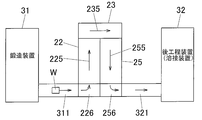
- a continuous heat treatment furnace as shown in FIG. 8 can also be employed.
- This continuous heat treatment furnace is disposed between a forging device 31 and a post-processing device 32 such as a welding device, and includes a solution treatment zone 22, a water tank zone 23, and an aging zone 25.
- the solution treatment zone 22 and the aging zone 25 are arranged in parallel, and in the solution treatment zone 22, the conveyance conveyor 225 for conveying the material W to be processed, and the aging zone 25
- the transport conveyor 255 that transports the workpiece W is arranged in parallel and in the opposite direction.
- the downstream side of the solution zone 22 and the upstream side of the aging zone 25 are arranged correspondingly, and the upstream side of the solution zone 22 and the downstream side of the aging zone 25 are arranged correspondingly. Yes.
- an upstream side (carrying-in port) of the water tank zone 23 is disposed corresponding to the downstream end of the solution zone 22, and a downstream side (discharge) of the water tank zone 23 corresponding to the upstream end of the aging zone 25.
- the material W to be processed that has been carried into the water tank zone 23 from the solution zone 22 passes through the water tank zone 23 by the conveyor 235 and is carried into the aging zone 25.
- the material W to be treated that has passed through the solution zone 22 is folded back (around the U-turn) around the water tank zone 23 and passes through the aging zone 25.
- the conveyor 235 in the water tank zone 23 can pass the material W to be processed into the water in the water tank, similarly to the continuous heat treatment furnace shown in FIG.
- the lengths of the solution treatment zone 22 and the aging zone 25 are increased. Will be different. However, the lengths of the solution zone 22 and the aging zone 25 can be matched by adjusting the conveyance speeds of the solution conveyors 225 and 255 in the solution zone 22 and the aging zone 25.
- a turntable 226 is disposed on the upstream side of the solution solution zone 22, and a conveyer 311 is disposed between the turntable 226 and the forging device 31. Accordingly, the workpiece W carried out from the forging device 31 is conveyed to the turntable 226 by the conveyer 311, rotated by the turntable 226, adjusted in direction, and then carried into the solution zone 22. It has become.
- a turntable 256 is disposed on the downstream side of the aging zone 25, and a conveyor conveyer 321 is disposed between the turntable 256 and the post-processing device 32. Therefore, the workpiece W carried out of the aging zone 25 is rotated by the turntable 256 and the direction thereof is adjusted, and then conveyed to the post-processing device 32 by the conveyance conveyor 321.
- each conveyor and turntable and the temperature of each heat treatment zone are controlled by a control device similar to the continuous heat treatment furnace of FIG.
- the material W to be processed as an Al forged member forged by the forging device 31 is carried into the solution zone 22 via the conveyor 311 and the turntable 226 and passes through the solution zone 22. Solution treatment.
- the to-be-processed material W carried into the water tank zone 23 from the solution zone 22 is quenched by passing through the water in the water tank.
- the material to be treated W introduced from the water tank zone 23 to the aging zone 25 passes through the aging zone 25 and is subjected to aging treatment.
- the material W to be processed is transported to the post-process device 32 by the turntable 256 and the transport conveyor 321 and subjected to a welding process or the like.
- solution treatment, quenching treatment, and aging treatment can be performed automatically and continuously as described above, and production efficiency can be improved.
- the solution treatment zone 22 and the aging zone 25 are arranged in parallel and the conveying direction is reversed, and the material W to be treated passing through the solution treatment zone 22 is in the peripheral portion of the water tank zone 23. It turns around and passes through the aging zone 25. For this reason, the outlet of the solution zone 22 (the inlet of the water tank zone 23) and the inlet of the aging zone 25 (the outlet of the water tank zone 23) are formed on one side wall (same wall surface) of the water tank zone 23. be able to. As a result, the solution zone 22, the aging zone 25, and the like can be arranged at arbitrary positions between the forging device 31 and the post-processing device (for example, a welding processing device) 32. Accordingly, the degree of freedom in design increases, and a production system (manufacturing apparatus) in which each zone is arranged at an optimal position can be constructed.
- a post-processing device welding processing device
- a continuous heat treatment furnace such as the heat treatment zones 22 and 25 from the process conveyor.
- a solution temperature increase zone, an aging temperature increase zone, an aging temperature decrease zone, and the like may be provided as necessary.
- a partition door may be provided between each of the plurality of zones.
- a molten Al alloy corresponding to each sample thus obtained was cast into a mold, and a disk sample 3 having a shape as shown in FIG. 3 was collected and analyzed by emission spectroscopic analysis described in JIS H 1305.
- s1 to s6 of the disk sample 3 are as follows. That is, s1 is 18 mm, s2 is 30 mm, s3 is 50 mm, s4 is 35 mm, s5 is 5 mm, and s6 is 5 mm.
- the ingot corresponding to each sample obtained in this way was subjected to peripheral cutting so as to have a diameter of 60 mm with a lathe, then cut to a standard length, and homogenized under the conditions shown in Table 2A.
- peripheral cutting so as to have a diameter of 60 mm with a lathe, then cut to a standard length, and homogenized under the conditions shown in Table 2A.
- the surface state was confirmed visually and the presence or absence of local melting was confirmed.
- the continuous casting round bar after the homogenization process was cut
- the pre-heated material was preheated under the conditions shown in Table 2A, and then installed to a thickness of 35 mm from the side of the round bar. Prior to upsetting, the surface condition was visually confirmed to check for local melting. In addition, after upsetting, the presence or absence of cracks on the sample surface was confirmed by a solvent-removable penetrant flaw detection test (color check). The subsequent upset (forged member) was held at the solution temperature shown in Table 2A for 3 hours, then quenched with water, and immediately after that, an aging treatment was performed under the conditions shown in Table 2A. About the sample after solution treatment, the surface state was confirmed visually and the presence or absence of local melting was confirmed.
- each sample after solution treatment a sample subjected to two-stage aging treatment was also prepared for comparison.
- each sample after the solution treatment is subjected to a first-stage aging treatment that is held at 110 ° C. for 6 hours, and then a second-stage aging treatment that is held at 150 ° C. for 8 hours, thereby performing a two-stage aging treatment.
- Each sample was also prepared.
- Example 10 is the same as Example 1 except that the ratio of the aging treatment time to the solution treatment time is described as described later.
- JIS14B proportional test pieces were collected from the obtained samples at the welded portion and the base metal portion, and the tensile strength [MPa] was measured.
- the Vickers hardness of the heat affected zone 15 during welding (see FIG. 4B) and the end portion not affected by heat (the other portion 16) is measured, and the Vickers hardness of the heat affected zone 15 during welding is measured.
- the value (ratio) divided by the Vickers hardness of the end portion 16 not affected by heat is 0.8 or more, it is judged that the hardness recovery performance of the heat affected zone 15 is “good”, 0.8 It was judged that the hardness recovery performance of the heat affected zone 15 was “bad (bad)”.
- a 2 mm ⁇ 4.3 mm ⁇ 42.4 mm test piece was cut out from the upset product (forged product sample), and the yield strength was measured using a three-point bending jig at the center of the 4.3 mm ⁇ 42.4 mm surface. A stress corresponding to 70% of the above was applied. During the load, the test piece and the jig were electrically insulated. As a corrosive solution, 36 g of chromium (IV) oxide, 30 g of potassium dichromate and 3 g of sodium chloride were dissolved per liter of pure water, and a solution maintained at 95 to 100 ° C. was prepared. After the test piece loaded with stress was immersed in the corrosive liquid for 16 hours, the appearance of the test piece was observed to confirm whether cracks were generated.
- chromium (IV) oxide, 30 g of potassium dichromate and 3 g of sodium chloride were dissolved per liter of pure water, and a solution maintained at 95 to 100 ° C. was prepared. After the
- Example 1 to 7, 11, and 12 satisfy all the requirements of the present invention, so that no ingot cracking, weld cracking, forging cracking, and local melting occur, and tensile strength
- the joint efficiency is excellent, and there is little difference in strength between the one-stage aging-treated product and the two-stage aging-treated product, and it can be seen that sufficient strength is obtained by one-step aging. Moreover, stress corrosion cracking did not occur.
- “joint efficiency” has the same meaning as the hardness recovery performance of the heat affected zone. Since Example 10 has substantially the same conditions as Example 1, the same result as Example 1 is obtained.
- the ratio of the aging treatment time to the solution treatment time is 1 to 6, and the solution treatment The time is not so different from the solution treatment time.
- Comparative Example 4 the Cu content was slightly lower and the Mg content was also lower. For the same reason as in Comparative Example 3, excellent tensile strength was not obtained with the one-stage aging product, and Thus, the strength of the one-stage aging product was significantly reduced.
- Example 1 to 4 related to the present invention there is no difference in strength (rate of change in strength) between the one-stage aging-treated product and the two-stage aging-treated product, and the preferred and sufficient strength (single-step aging treatment) 460 MPa or more, more preferably 500 MPa or more), and a practical product that does not cause cracking could be obtained.
- Comparative Examples 3 and 4 the difference in strength between the one-stage aging-treated product and the two-stage aging-treated product was large, and two-stage aging treatment was required in order to obtain a preferable sufficient strength.
- the sufficient and sufficient strength was obtained by the one-stage aging treatment, but cracking occurred and it was not practical, and the preferable and sufficient strength could not be obtained, so that it was not practical.
- Table 5 shows DAS ( ⁇ m) and average particle size ( ⁇ m) of the crystallized material in the Al alloy ingots (samples) of Examples 1 (10) to 7, 11, and 12.
- Al alloy having high strength, desired mechanical characteristics and stress corrosion cracking resistance performance without losing hardness recovery performance after welding can be obtained. Furthermore, an Al alloy product having the desired characteristics can be reliably and efficiently manufactured by a one-step aging treatment simplified in a short time of 130 to 170 ° C. ⁇ 8 to 12 Hr.
- the method for producing an Al alloy joined body of the present invention can be applied to a forging / welding technique for producing a high-quality Al alloy product.
Landscapes
- Chemical & Material Sciences (AREA)
- Mechanical Engineering (AREA)
- Engineering & Computer Science (AREA)
- Materials Engineering (AREA)
- Organic Chemistry (AREA)
- Metallurgy (AREA)
- Thermal Sciences (AREA)
- Crystallography & Structural Chemistry (AREA)
- Physics & Mathematics (AREA)
- Forging (AREA)
- Arc Welding In General (AREA)
- Continuous Casting (AREA)
- Butt Welding And Welding Of Specific Article (AREA)
Abstract
La présente invention se rapporte à un procédé qui permet de fabriquer de façon efficace un corps constitué d'un alliage d'aluminium (Al) qui est léger et qui présente une résistance élevée. De façon précise, la présente invention se rapporte à un procédé de fabrication d'un corps constitué d'un alliage d'aluminium (Al) qui comprend : une étape consistant à obtenir un alliage d'aluminium (Al) en fusion composé d'un alliage d'aluminium (Al), de zinc (Zn) et de magnésium (Mg) qui a une composition d'alliage spécifique; une étape consistant à obtenir un lingot d'alliage d'aluminium (Al) qui présente une structure spécifique en coulant en continu l'alliage d'aluminium (Al) en fusion à une vitesse de coulée spécifique; une étape consistant à obtenir un élément d'alliage d'aluminium (Al) en fusion en soumettant le lingot d'alliage d'aluminium (Al) à un traitement d'homogénéisation spécifique; une étape consistant à obtenir un élément d'alliage d'aluminium forgé en soumettant l'élément d'aluminium (Al) en fusion à un forgeage à chaud; une étape consistant à soumettre l'élément d'alliage d'aluminium (Al) forgé à un traitement thermique de mise en solution; une étape consistant à soumettre l'élément d'alliage d'aluminium (Al) forgé après le traitement thermique de mise en solution à un traitement de vieillissement en une seule étape; et une étape consistant à obtenir un corps constitué d'un alliage d'aluminium (Al) en soudant l'élément d'alliage d'aluminium (Al) forgé après le traitement de vieillissement en une seule étape à un composant qui doit être assemblé, ledit composant étant formé d'un alliage d'aluminium (Al).
Priority Applications (2)
| Application Number | Priority Date | Filing Date | Title |
|---|---|---|---|
| JP2012519440A JP5819294B2 (ja) | 2010-06-11 | 2011-06-10 | Al合金接合体の製造方法 |
| EP11792566.9A EP2592170B1 (fr) | 2010-06-11 | 2011-06-10 | Procédé de fabrication d'un corps constitué d'un alliage d'aluminium (al) |
Applications Claiming Priority (2)
| Application Number | Priority Date | Filing Date | Title |
|---|---|---|---|
| JP2010134024 | 2010-06-11 | ||
| JP2010-134024 | 2010-06-11 |
Publications (1)
| Publication Number | Publication Date |
|---|---|
| WO2011155609A1 true WO2011155609A1 (fr) | 2011-12-15 |
Family
ID=45098212
Family Applications (1)
| Application Number | Title | Priority Date | Filing Date |
|---|---|---|---|
| PCT/JP2011/063406 WO2011155609A1 (fr) | 2010-06-11 | 2011-06-10 | Procédé de fabrication d'un corps constitué d'un alliage d'aluminium (al) |
Country Status (3)
| Country | Link |
|---|---|
| EP (1) | EP2592170B1 (fr) |
| JP (2) | JP5819294B2 (fr) |
| WO (1) | WO2011155609A1 (fr) |
Cited By (11)
| Publication number | Priority date | Publication date | Assignee | Title |
|---|---|---|---|---|
| JP2013209714A (ja) * | 2012-03-30 | 2013-10-10 | Kobe Steel Ltd | 自動車用アルミニウム合金鍛造部材およびその製造方法 |
| CN104191169A (zh) * | 2014-08-06 | 2014-12-10 | 江苏亚太安信达铝业有限公司 | 一种电器用支架的锻造工艺 |
| JP2015007273A (ja) * | 2013-06-25 | 2015-01-15 | 株式会社神戸製鋼所 | 溶接構造部材用アルミニウム合金鍛造材およびその製造方法 |
| JP2015007274A (ja) * | 2013-06-25 | 2015-01-15 | 株式会社神戸製鋼所 | 溶接構造部材用アルミニウム合金鍛造材およびその製造方法 |
| CN106001339A (zh) * | 2016-05-26 | 2016-10-12 | 钢铁研究总院华东分院 | 适配于特冶锻造新流程的特钢制造系统和特冶锻造新流程 |
| JP2019512607A (ja) * | 2016-07-13 | 2019-05-16 | アップル インコーポレイテッドApple Inc. | 高い強度及び美的訴求力を有するアルミニウム合金 |
| CN110230014A (zh) * | 2019-06-04 | 2019-09-13 | 燕山大学 | 一种调控铝合金锻件晶粒组织均匀性的方法 |
| US10597762B2 (en) | 2013-09-30 | 2020-03-24 | Apple Inc. | Aluminum alloys with high strength and cosmetic appeal |
| CN111440974A (zh) * | 2020-04-28 | 2020-07-24 | 北京工业大学 | 一种高强度铝合金及其制造方法 |
| US11345980B2 (en) | 2018-08-09 | 2022-05-31 | Apple Inc. | Recycled aluminum alloys from manufacturing scrap with cosmetic appeal |
| CN115386752A (zh) * | 2022-09-06 | 2022-11-25 | 昆明冶金研究院有限公司 | 一种汽车悬挂部件用铝合金锻件制造方法及汽车悬挂锻件 |
Families Citing this family (5)
| Publication number | Priority date | Publication date | Assignee | Title |
|---|---|---|---|---|
| CN104028692B (zh) * | 2014-06-11 | 2016-01-13 | 西北工业大学 | 发动机双合金轮盘的锻造方法 |
| CN104148897B (zh) * | 2014-08-06 | 2016-05-18 | 江苏亚太安信达铝业有限公司 | 一种电器用支架的锻造工艺 |
| CN108160966B (zh) * | 2017-12-29 | 2019-10-18 | 西南铝业(集团)有限责任公司 | 一种锌含量为9%~13%的铝合金半连续铸造方法 |
| CN109482796B (zh) * | 2018-12-11 | 2020-09-22 | 陕西宏远航空锻造有限责任公司 | 一种TC4钛合金盘锻件的β锻及热处理方法 |
| CN113106236A (zh) * | 2021-03-30 | 2021-07-13 | 桂林理工大学 | 一种降低铝合金搅拌摩擦焊接接头腐蚀敏感性的方法 |
Citations (9)
| Publication number | Priority date | Publication date | Assignee | Title |
|---|---|---|---|---|
| JPS5110113A (ja) | 1974-07-15 | 1976-01-27 | Sumitomo Light Metal Ind | Saiketsushososhikiochoseishita allznnmg keigokinoshidashizainarabinisono seizoho |
| JPS57158360A (en) | 1981-03-25 | 1982-09-30 | Kobe Steel Ltd | Manufacture of forged aluminum alloy product |
| JPH0270044A (ja) | 1988-09-06 | 1990-03-08 | Mitsubishi Alum Co Ltd | 熱間鍛造用アルミニウム合金鋳造棒の製造方法 |
| JPH03122243A (ja) * | 1989-10-04 | 1991-05-24 | Furukawa Alum Co Ltd | 耐応力腐食割れ性に優れる溶接用高力アルミニウム合金板材 |
| JPH073353A (ja) * | 1993-06-21 | 1995-01-06 | Kobe Steel Ltd | Al−Zn−Mg系合金の製造方法 |
| JP2001115227A (ja) * | 1999-10-15 | 2001-04-24 | Furukawa Electric Co Ltd:The | 表面性状に優れた高強度アルミニウム合金押出材および前記押出材を用いた二輪車用フレーム |
| JP2002348631A (ja) * | 2001-05-22 | 2002-12-04 | Aisin Seiki Co Ltd | アルミニウム−亜鉛−マグネシウム系の鋳造鍛造用アルミニウム合金、アルミニウム−亜鉛−マグネシウム系の鋳造鍛造品、及び、その製造方法 |
| JP2006505695A (ja) * | 2002-11-06 | 2006-02-16 | ペシネイ レナリュ | Al−Zn−Mg合金製の圧延製品の簡易製造法、およびこの方法によって得られる製品 |
| JP2010261061A (ja) * | 2009-04-30 | 2010-11-18 | Showa Denko Kk | Al合金鍛造製品の製造方法 |
Family Cites Families (3)
| Publication number | Priority date | Publication date | Assignee | Title |
|---|---|---|---|---|
| JPH07252573A (ja) * | 1994-03-17 | 1995-10-03 | Kobe Steel Ltd | 靭性に優れたAl−Zn−Mg−Cu系合金及びその製造方法 |
| JP4768925B2 (ja) * | 2001-03-30 | 2011-09-07 | 昭和電工株式会社 | 塑性加工用アルミニウム合金鋳塊の製造方法、アルミニウム合金塑性加工品の製造方法およびアルミニウム合金塑性加工品 |
| JP4933891B2 (ja) * | 2006-12-15 | 2012-05-16 | 古河スカイ株式会社 | 耐応力腐食割れ性に優れた溶接可能な鍛造用アルミニウム合金およびそれを用いた鍛造品 |
-
2011
- 2011-06-10 EP EP11792566.9A patent/EP2592170B1/fr active Active
- 2011-06-10 JP JP2012519440A patent/JP5819294B2/ja active Active
- 2011-06-10 WO PCT/JP2011/063406 patent/WO2011155609A1/fr active Application Filing
-
2015
- 2015-08-06 JP JP2015155702A patent/JP5972438B2/ja active Active
Patent Citations (9)
| Publication number | Priority date | Publication date | Assignee | Title |
|---|---|---|---|---|
| JPS5110113A (ja) | 1974-07-15 | 1976-01-27 | Sumitomo Light Metal Ind | Saiketsushososhikiochoseishita allznnmg keigokinoshidashizainarabinisono seizoho |
| JPS57158360A (en) | 1981-03-25 | 1982-09-30 | Kobe Steel Ltd | Manufacture of forged aluminum alloy product |
| JPH0270044A (ja) | 1988-09-06 | 1990-03-08 | Mitsubishi Alum Co Ltd | 熱間鍛造用アルミニウム合金鋳造棒の製造方法 |
| JPH03122243A (ja) * | 1989-10-04 | 1991-05-24 | Furukawa Alum Co Ltd | 耐応力腐食割れ性に優れる溶接用高力アルミニウム合金板材 |
| JPH073353A (ja) * | 1993-06-21 | 1995-01-06 | Kobe Steel Ltd | Al−Zn−Mg系合金の製造方法 |
| JP2001115227A (ja) * | 1999-10-15 | 2001-04-24 | Furukawa Electric Co Ltd:The | 表面性状に優れた高強度アルミニウム合金押出材および前記押出材を用いた二輪車用フレーム |
| JP2002348631A (ja) * | 2001-05-22 | 2002-12-04 | Aisin Seiki Co Ltd | アルミニウム−亜鉛−マグネシウム系の鋳造鍛造用アルミニウム合金、アルミニウム−亜鉛−マグネシウム系の鋳造鍛造品、及び、その製造方法 |
| JP2006505695A (ja) * | 2002-11-06 | 2006-02-16 | ペシネイ レナリュ | Al−Zn−Mg合金製の圧延製品の簡易製造法、およびこの方法によって得られる製品 |
| JP2010261061A (ja) * | 2009-04-30 | 2010-11-18 | Showa Denko Kk | Al合金鍛造製品の製造方法 |
Non-Patent Citations (2)
| Title |
|---|
| "Light Metal", vol. 38, 1988, JAPAN INSTITUTE OF LIGHT METALS, article "Dendri te Arm Spacing Measurement Method", pages: 45 |
| See also references of EP2592170A4 |
Cited By (13)
| Publication number | Priority date | Publication date | Assignee | Title |
|---|---|---|---|---|
| JP2013209714A (ja) * | 2012-03-30 | 2013-10-10 | Kobe Steel Ltd | 自動車用アルミニウム合金鍛造部材およびその製造方法 |
| JP2015007273A (ja) * | 2013-06-25 | 2015-01-15 | 株式会社神戸製鋼所 | 溶接構造部材用アルミニウム合金鍛造材およびその製造方法 |
| JP2015007274A (ja) * | 2013-06-25 | 2015-01-15 | 株式会社神戸製鋼所 | 溶接構造部材用アルミニウム合金鍛造材およびその製造方法 |
| US10597762B2 (en) | 2013-09-30 | 2020-03-24 | Apple Inc. | Aluminum alloys with high strength and cosmetic appeal |
| CN104191169A (zh) * | 2014-08-06 | 2014-12-10 | 江苏亚太安信达铝业有限公司 | 一种电器用支架的锻造工艺 |
| CN106001339A (zh) * | 2016-05-26 | 2016-10-12 | 钢铁研究总院华东分院 | 适配于特冶锻造新流程的特钢制造系统和特冶锻造新流程 |
| JP7051700B2 (ja) | 2016-07-13 | 2022-04-11 | アップル インコーポレイテッド | 高い強度及び美的訴求力を有するアルミニウム合金 |
| JP2019512607A (ja) * | 2016-07-13 | 2019-05-16 | アップル インコーポレイテッドApple Inc. | 高い強度及び美的訴求力を有するアルミニウム合金 |
| US10544493B2 (en) | 2016-07-13 | 2020-01-28 | Apple Inc. | Aluminum alloys with high strength and cosmetic appeal |
| US11345980B2 (en) | 2018-08-09 | 2022-05-31 | Apple Inc. | Recycled aluminum alloys from manufacturing scrap with cosmetic appeal |
| CN110230014A (zh) * | 2019-06-04 | 2019-09-13 | 燕山大学 | 一种调控铝合金锻件晶粒组织均匀性的方法 |
| CN111440974A (zh) * | 2020-04-28 | 2020-07-24 | 北京工业大学 | 一种高强度铝合金及其制造方法 |
| CN115386752A (zh) * | 2022-09-06 | 2022-11-25 | 昆明冶金研究院有限公司 | 一种汽车悬挂部件用铝合金锻件制造方法及汽车悬挂锻件 |
Also Published As
| Publication number | Publication date |
|---|---|
| JP5972438B2 (ja) | 2016-08-17 |
| JP2016013576A (ja) | 2016-01-28 |
| JPWO2011155609A1 (ja) | 2013-08-15 |
| JP5819294B2 (ja) | 2015-11-24 |
| EP2592170A1 (fr) | 2013-05-15 |
| EP2592170B1 (fr) | 2019-01-02 |
| EP2592170A4 (fr) | 2017-06-28 |
Similar Documents
| Publication | Publication Date | Title |
|---|---|---|
| JP5972438B2 (ja) | Al合金鋳造部材の製造方法 | |
| JP5678099B2 (ja) | 構造部材製造用アルミニウム合金製品およびその製造方法 | |
| JP4801386B2 (ja) | アルミ合金製塑性加工品、その製造方法、自動車用部品、時効処理炉、およびアルミ合金製塑性加工品の製造システム | |
| TWI592498B (zh) | Aluminum alloy plastic processed products, manufacturing method thereof and automobile parts | |
| JP5698695B2 (ja) | 自動車用アルミニウム合金鍛造材およびその製造方法 | |
| US9194029B2 (en) | Process for producing cast aluminum alloy member | |
| TWI507532B (zh) | High strength aluminum magnesium silicon alloy and its manufacturing process | |
| WO2013114928A1 (fr) | Matériau d'alliage d'aluminium forgé et son procédé de fabrication | |
| JP2013525608A (ja) | 階層状の微細構造を有する損傷耐性アルミ材 | |
| US20210008671A1 (en) | Extrusion Material | |
| JP5275321B2 (ja) | アルミ合金製塑性加工品の製造方法 | |
| JP2022512990A (ja) | 急速に時効した高強度かつ熱処理可能なアルミニウム合金製品、及びそれを製造する方法 | |
| JP3726087B2 (ja) | 輸送機構造材用アルミニウム合金鍛造材およびその製造方法 | |
| JP5308907B2 (ja) | Al合金鍛造製品の製造方法 | |
| JP5532462B2 (ja) | アルミ合金製塑性加工品の製造方法 | |
| US12031199B2 (en) | Aluminum alloy compositions, articles therefrom, and methods of producing articles therefrom | |
| WO2012060359A1 (fr) | Pièce en alliage de cuivre forgée à chaud et son procédé de fabrication | |
| JP2009041113A (ja) | 自動車用部品 | |
| US20240026497A1 (en) | Aluminum Alloy Compositions, Articles Therefrom, and Methods of Producing Articles Therefrom | |
| KR101206830B1 (ko) | 거푸집 압출용 알루미늄 합금과, 그 알루미늄 합금으로 이루어진 알루미늄 거푸집의 제조방법 | |
| JPH08165539A (ja) | 熱処理型薄肉アルミニウム押出し形材及びその製造方法 | |
| JPH042741A (ja) | 耐応力腐食割れ性に優れた溶接構造材用高力アルミニウム合金 | |
| CN118600291A (zh) | 一种含有Mo元素的无粗晶且耐热的7系铝合金及其制备方法 | |
| Langan et al. | High Strength, Lightweight Car Bodies for High-Speed Rail Vehicles | |
| JP2018199854A (ja) | 溶接用アルミニウム合金板及び溶接用アルミニウム合金板製造方法 |
Legal Events
| Date | Code | Title | Description |
|---|---|---|---|
| 121 | Ep: the epo has been informed by wipo that ep was designated in this application |
Ref document number: 11792566 Country of ref document: EP Kind code of ref document: A1 |
|
| WWE | Wipo information: entry into national phase |
Ref document number: 2012519440 Country of ref document: JP |
|
| NENP | Non-entry into the national phase |
Ref country code: DE |
|
| WWE | Wipo information: entry into national phase |
Ref document number: 2011792566 Country of ref document: EP |