WO2011155609A1 - Method for producing al alloy joined body - Google Patents
Method for producing al alloy joined body Download PDFInfo
- Publication number
- WO2011155609A1 WO2011155609A1 PCT/JP2011/063406 JP2011063406W WO2011155609A1 WO 2011155609 A1 WO2011155609 A1 WO 2011155609A1 JP 2011063406 W JP2011063406 W JP 2011063406W WO 2011155609 A1 WO2011155609 A1 WO 2011155609A1
- Authority
- WO
- WIPO (PCT)
- Prior art keywords
- alloy
- mass
- treatment
- aging
- zone
- Prior art date
Links
Images


Classifications
-
- C—CHEMISTRY; METALLURGY
- C22—METALLURGY; FERROUS OR NON-FERROUS ALLOYS; TREATMENT OF ALLOYS OR NON-FERROUS METALS
- C22C—ALLOYS
- C22C21/00—Alloys based on aluminium
- C22C21/10—Alloys based on aluminium with zinc as the next major constituent
-
- B—PERFORMING OPERATIONS; TRANSPORTING
- B21—MECHANICAL METAL-WORKING WITHOUT ESSENTIALLY REMOVING MATERIAL; PUNCHING METAL
- B21J—FORGING; HAMMERING; PRESSING METAL; RIVETING; FORGE FURNACES
- B21J1/00—Preparing metal stock or similar ancillary operations prior, during or post forging, e.g. heating or cooling
-
- B—PERFORMING OPERATIONS; TRANSPORTING
- B22—CASTING; POWDER METALLURGY
- B22D—CASTING OF METALS; CASTING OF OTHER SUBSTANCES BY THE SAME PROCESSES OR DEVICES
- B22D11/00—Continuous casting of metals, i.e. casting in indefinite lengths
- B22D11/001—Continuous casting of metals, i.e. casting in indefinite lengths of specific alloys
- B22D11/003—Aluminium alloys
-
- B—PERFORMING OPERATIONS; TRANSPORTING
- B22—CASTING; POWDER METALLURGY
- B22D—CASTING OF METALS; CASTING OF OTHER SUBSTANCES BY THE SAME PROCESSES OR DEVICES
- B22D11/00—Continuous casting of metals, i.e. casting in indefinite lengths
- B22D11/12—Accessories for subsequent treating or working cast stock in situ
- B22D11/1213—Accessories for subsequent treating or working cast stock in situ for heating or insulating strands
-
- B—PERFORMING OPERATIONS; TRANSPORTING
- B32—LAYERED PRODUCTS
- B32B—LAYERED PRODUCTS, i.e. PRODUCTS BUILT-UP OF STRATA OF FLAT OR NON-FLAT, e.g. CELLULAR OR HONEYCOMB, FORM
- B32B15/00—Layered products comprising a layer of metal
- B32B15/01—Layered products comprising a layer of metal all layers being exclusively metallic
- B32B15/016—Layered products comprising a layer of metal all layers being exclusively metallic all layers being formed of aluminium or aluminium alloys
-
- C—CHEMISTRY; METALLURGY
- C22—METALLURGY; FERROUS OR NON-FERROUS ALLOYS; TREATMENT OF ALLOYS OR NON-FERROUS METALS
- C22F—CHANGING THE PHYSICAL STRUCTURE OF NON-FERROUS METALS AND NON-FERROUS ALLOYS
- C22F1/00—Changing the physical structure of non-ferrous metals or alloys by heat treatment or by hot or cold working
- C22F1/04—Changing the physical structure of non-ferrous metals or alloys by heat treatment or by hot or cold working of aluminium or alloys based thereon
- C22F1/053—Changing the physical structure of non-ferrous metals or alloys by heat treatment or by hot or cold working of aluminium or alloys based thereon of alloys with zinc as the next major constituent
-
- A—HUMAN NECESSITIES
- A63—SPORTS; GAMES; AMUSEMENTS
- A63B—APPARATUS FOR PHYSICAL TRAINING, GYMNASTICS, SWIMMING, CLIMBING, OR FENCING; BALL GAMES; TRAINING EQUIPMENT
- A63B2209/00—Characteristics of used materials
-
- B—PERFORMING OPERATIONS; TRANSPORTING
- B23—MACHINE TOOLS; METAL-WORKING NOT OTHERWISE PROVIDED FOR
- B23K—SOLDERING OR UNSOLDERING; WELDING; CLADDING OR PLATING BY SOLDERING OR WELDING; CUTTING BY APPLYING HEAT LOCALLY, e.g. FLAME CUTTING; WORKING BY LASER BEAM
- B23K2103/00—Materials to be soldered, welded or cut
- B23K2103/08—Non-ferrous metals or alloys
- B23K2103/10—Aluminium or alloys thereof
Definitions
- the present invention relates to a method for manufacturing an Al alloy joined body in which an Al (aluminum) alloy is joined by welding, and a related technique.
- Al-Zn-Mg Al alloys are often used as structural materials because of their excellent strength and workability.
- Patent Documents 1 to 3 in order to secure sufficient strength in conventional Al—Zn—Mg alloys, complex heat treatment is required for a long time as an aging treatment. There is a problem that it is difficult to improve the performance. Further, when trying to simplify the heat treatment, there is a problem that sufficient strength cannot be obtained, reinforcement by thickening or the like is required, and it is difficult to reduce the weight.
- the present invention has been made in view of the above problems, and an object of the present invention is to provide an Al alloy joined body manufacturing method and related technology capable of efficiently producing a high-strength and lightweight Al alloy joined body.
- the present invention has the following configuration.
- an Al alloy ingot having a structure of 40 ⁇ m or less and a crystallite having an average particle size of 8 ⁇ m or less;
- For the Al alloy cast member performing hot forging to obtain an Al alloy forged member;
- the casting speed is a speed at which the ingot is pulled from the mold, and is obtained by measuring the moving speed of the ingot per unit time. At the time of casting, the speed is gradually increased from the stopped state, and the maximum speed is reached when the casting is stable. In the present invention, this maximum speed is referred to as the maximum casting speed.
- the one-stage aging treatment refers to an aging treatment once (once) in a relatively short time.
- the one-stage aging process of the present invention is a single aging process, and is different from the two-stage aging process in which the first-stage aging process and the second-stage aging process are performed twice.
- the one-step aging treatment of the present invention is a relatively short time, and is different from a one-step aging treatment in which a complicated one-step aging treatment is performed for a long time, for example, a complicated temperature control is performed for a long time of 24 hours or more.
- the room temperature treatment may be performed, or after the solution treatment, the one-step aging treatment is performed immediately without performing the room temperature treatment. You may make it do.
- An apparatus for manufacturing an Al alloy joined body characterized by the above.
- a water tank zone further comprising a quenching water tank in which water is stored between the solution heat treatment zone and the one-stage aging heat treatment zone, After performing the solution treatment, before performing the one-stage aging treatment, the material to be treated is passed through the water tank of the water tank zone and the quenching process is performed. Manufacturing equipment.
- the solution heat treatment zone and the one-stage aging heat treatment zone are arranged in parallel, and the conveying direction of the material to be treated is opposite to each other,
- the carry-out side end of the solution heat treatment zone and the carry-in side end of the one-stage aging heat treatment zone are arranged correspondingly, 9.
- a step based on the step of obtaining the Al alloy ingot and a step based on the step of obtaining the Al alloy cast member were sequentially performed.
- the actual characteristics obtained from the prototype Al alloy forged member are compared with the target characteristics, and based on the comparison result, the fourth preparation step of changing the temporary value, 11.
- the method for producing an Al alloy cast member according to item 10 wherein the third and fourth preparation steps are repeatedly performed to prepare an Al alloy molten metal to be actually used.
- an Al alloy ingot having a structure of 40 ⁇ m or less and a crystallite having an average particle size of 8 ⁇ m or less;
- a step of obtaining an Al alloy cast member by subjecting the Al alloy ingot to a homogenization treatment for holding at a temperature of 400 to 600 ° C. for 1 hour or more;
- For the Al alloy cast member performing hot forging to obtain an Al alloy forged member;
- a step of subjecting the Al alloy forged member after solution treatment to a one-step aging treatment are examples of the Al alloy cast member after solution treatment.
- a step based on the step of obtaining the Al alloy ingot, a step based on the step of obtaining the Al alloy cast member, and the Al alloy forging are sequentially performed to obtain a prototype Al alloy forged member.
- a target aging time in the temporary aging treatment is set in advance
- the actual aging time is measured
- the actual aging time is compared with the target aging time, and the temporary value is changed based on the comparison result. Manufacturing method.
- a plurality of joined parts made of an Al alloy are welded, and a welded portion is provided at a welded portion between the joined parts, and heat that is affected by heat in the vicinity of the welded portion is exerted.
- An Al alloy joined body provided with an affected part Among the plurality of joined parts, at least one joined part is Fe: 0.2 to 0.35 mass%, Cu: 0.1 to 0.4 mass%, Mn: 0.3 to 0.6 Wt%, Mg: 2.0-2.5 wt%, Zn: 5.0-5.5 wt%, Zr: 0.1-0.2 wt%, Ti: 0.2 wt% or less,
- the balance has an alloy composition consisting of Al and inevitable impurities, The relationship of “V 1 / V 2 ⁇ 0.8” is established, where the hardness of the heat affected zone is “V 1 ” and the average hardness of the portion not affected by the heat caused by welding is “V 2 ”.
- an Al alloy forged product having high strength, desired mechanical characteristics and corrosion resistance performance can be obtained without losing hardness recovery performance after welding. Can do. Moreover, since the one-step aging treatment can be simplified in a short time, an Al alloy joined body having the desired characteristics can be efficiently produced.
- the load that can be withstood in the entire area of the Al alloy joined body is increased, the weight of the Al alloy joined body can be reduced, and the weight can be reduced.
- hardness recovery performance after welding refers to the decrease rate of the Vickers hardness of the heat-affected zone by welding with respect to the Vickers hardness of the base material subjected to T6 treatment, specifically, When the decrease rate is 20% or less, it is judged that the hardness recovery performance after welding is good.
- hardness recovery performance after welding can be defined by the following relational expression.
- Hardness recovery performance after welding (“Vickers hardness of base material”-"Vickers hardness of heat affected zone”) / "Vickers hardness of base material” Further, in the present invention, a material having a tensile strength of 450 MPa or more is determined as “high strength”.
- the Vickers hardness is based on JIS Z 2244. Furthermore, the tensile strength conforms to JIS Z 2201 and JIS Z 2241.
- the aging treatment can be reliably performed and the production efficiency can be more reliably improved.
- an Al alloy joined body having the desired characteristics can be produced more efficiently.
- an Al alloy cast member optimum as an Al alloy joint part for welding can be produced.
- a desired Al alloy molten metal can be prepared and a high quality Al alloy cast member can be obtained.
- an Al alloy forged member for welding according to the invention [12] an Al alloy forged member optimum as an Al alloy joined part for welding can be produced.
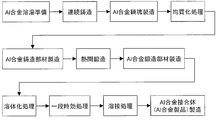
- FIG. 1 is a flowchart for explaining a method of manufacturing an Al alloy joined body according to an embodiment of the present invention.
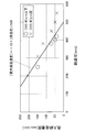
- FIG. 2 is a graph showing the relationship between the maximum casting speed and DSA in an Al alloy.
- FIG. 3 is a perspective view showing a disk sample for alloy composition analysis.
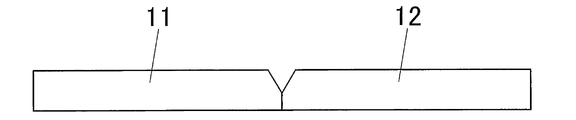
- FIG. 4A is a cross-sectional view showing a state immediately before welding joined parts made of Al alloy.
- FIG. 4B is a cross-sectional view showing a state immediately after the welded parts made of Al alloy are welded together.
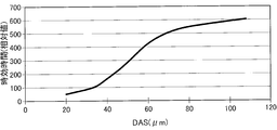
- FIG. 5 is a graph showing the relationship between DAS and aging time.
- FIG. 6 is a graph showing the relationship between the average particle size of the crystallization part and the elongation.
- FIG. 7 is a block diagram showing an example of an apparatus for manufacturing an Al alloy joined body according to the present invention.
- FIG. 8 is a block diagram showing another example of an apparatus for manufacturing an Al alloy joined body according to the present invention.
- FIG. 1 is a flowchart for explaining an example of a method for producing an Al alloy joined body according to an embodiment of the present invention.
- an Al alloy molten metal having a predetermined alloy composition is prepared, and an Al alloy ingot is obtained by continuously casting the Al alloy molten metal under predetermined conditions. Subsequently, the Al alloy ingot is homogenized to obtain an Al alloy cast member. Thereafter, hot forging is performed on the Al alloy cast member to obtain an Al alloy forged member. Further, the Al alloy forged member is subjected to a solution treatment and then subjected to a one-stage aging treatment. Then, without performing the aging treatment (second-stage aging treatment), the Al alloy forged members obtained by joining and integrating the Al alloy forged members after the first-stage aging treatment by welding treatment to form the Al alloy product of the present embodiment Is what you get.
- the molten Al alloy as an Al casting material used in the present invention is 0.2 to 0.35 mass% Fe, 0.1 to 0.4 mass% Cu, and 0.3 to 0.6 mass% Mn.
- Mg 2.0 to 2.5 mass%, Zn 5.0 to 5.5 mass%, Zr 0.1 to 0.2 mass%, Ti 0.2 mass% or less, the balance being It has an alloy composition consisting of Al and inevitable impurities.
- Fe is an element that suppresses ingot cracking during casting and weld cracking during welding and suppresses coarse recrystallization.
- the Fe content (concentration) is It is necessary to adjust to 0.2 to 0.35 mass%.
- the Fe content is adjusted to 0.30 to 0.35 mass%.
- Cu not only increases the degree of supersaturation of the solute in the solid solution by dissolving in the aluminum matrix, but also coexists with Mg, thereby precipitating an Al—Cu—Mg intermetallic compound to impart strength. It is.
- Cu coexists with Mg, and the coexistence state with Mg is controlled so that the precipitation state of the Al—Cu—Mg intermetallic compound by aging treatment in the Al alloy becomes fine and dense.
- the behavior of the precipitation can be changed appropriately.
- Cu is a conventional two-stage aging treatment in which the second aging is performed at 140 to 190 ° C. for 2 to 24 hours after the first aging treatment at 80 to 130 ° C. for 1 to 16 hours.
- the relatively short time is, for example, 8 to 12 hours, preferably about 8 hours.
- the mechanism is estimated as follows.
- the Mg—Zn intermetallic compound is coarsely precipitated in the Al matrix at the initial stage of aging.
- the precipitation density becomes coarse, and the precipitation density remains rough even if the aging treatment is continued thereafter. For this reason, the aging effect is not sufficiently obtained, and the maximum value of the hardness is lowered. Therefore, in the past, the size at which the initial temperature of aging is lowered and the Mg—Zn-based intermetallic compound is finely precipitated in the Al matrix and then contributes to the increase in hardness by high-temperature aging treatment or long-term low-temperature aging treatment. The maximum value of hardness is raised by growing precipitates.
- a two-stage aging treatment of a low temperature short time and a high temperature short time or a one-step aging treatment of a low temperature and a long time must be used. Therefore, conventionally, this aging treatment requires a lot of time and complicated temperature control, which has been a factor in reducing productivity.
- the Al—Cu—Mg intermetallic compound can be finely and densely precipitated in the Al matrix at the initial stage of aging, and then Zn—Mg The intermetallic compound is deposited on the finely precipitated Al—Cu—Mg intermetallic compound.
- Zn—Mg-based intermetallic compounds grown to a size that contributes to strength are finely and densely present in the Al matrix, and the maximum value of hardness can be sufficiently increased.
- the Cu content (concentration) it is necessary to adjust the Cu content (concentration) to 0.1 to 0.4 mass%, more preferably 0.30 to 0.40 mass%.
- the Cu content is less than 0.1% by mass, the above effect cannot be obtained sufficiently, and the amount of the Al—Cu—Mg intermetallic compound generated at the early stage of aging is too small.
- the one-stage aging treatment is not desirable because the strength improvement effect cannot be obtained with certainty and a two-stage aging treatment is required.
- the Cu content exceeds 0.4% by mass, the strength is improved, but the stress corrosion cracking resistance is remarkably lowered and there is a risk of generating weld cracks, which is not desirable.
- Mn is an element that suppresses coarse recrystallization.
- it is necessary to adjust the Mn content (concentration) to 0.3 to 0.6% by mass, and preferably to 0.5 to 0.6% by mass.
- the Mn content is less than 0.3% by mass, the effect of suppressing coarse recrystallization is reduced.
- the Mn content exceeds 0.6% by mass, the Al—Fe—Mn-based coarse crystallized product increases, which impairs the plastic workability during forging.
- the processed Al alloy product is finally assembled to a vehicle body or the like, the ductility, toughness, and fatigue strength of the Al alloy product (assembled part) may be reduced.
- Mg is an element that precipitates MgZn 2 intermetallic compound ( ⁇ phase) and improves mechanical strength by coexisting with Zn. Furthermore, as described above, Mg can appropriately change the precipitation behavior of the Al—Cu—Mg intermetallic compound in the early stage of aging by coexisting with Cu. Therefore, Mg is subjected to the second stage aging treatment, which is conventionally performed at 80 to 130 ° C. for 1 to 16 hours and then the second stage aging treatment at 140 to 190 ° C. for 2 to 24 hours. In order to make it possible to obtain the same mechanical properties and anti-corrosion performance obtained by the treatment by performing a single aging treatment (one-step aging treatment) at 130 to 170 ° C. for a relatively short time. It is a necessary element.
- the relatively short time is, for example, 8 to 12 hours, preferably about 8 hours.
- the Mg content concentration
- 2.2 to 2.5% concentration of the Mg content
- the amount is too large, stress corrosion cracking resistance and quenching sensitivity are lowered, which is not desirable.
- Zn is an element that precipitates MgZn 2 intermetallic compound ( ⁇ phase) and improves mechanical strength by coexisting with Mg.
- the Zn content (concentration) it is necessary to adjust the Zn content (concentration) to 5.0 to 5.5% by mass, and more preferably to 5.2 to 5.5% by mass.
- the precipitation state of the Al—Cu—Mg intermetallic compound in which fine precipitation is progressing means that the Al—Cu—Mg intermetallic compound is in a state where the Al—Cu—Mg intermetallic compound is aligned with the parent phase.
- the state is formed in a rod shape in the 100> direction.
- the state in which the Al—Cu—Mg intermetallic compound is aligned with the parent phase means that the atoms forming the parent phase and the atoms of the Al—Cu—Mg intermetallic compound forming the precipitate are in a one-to-one relationship. It is in a state where it is formed with lattice point correspondence.
- (B-3) “The state in which a finely precipitated Al—Cu—Mg intermetallic compound is used as a nucleus and a Zn—Mg intermetallic compound is deposited thereon” means a Zn—Mg intermetallic compound. Is deposited on the surface of the Al—Cu—Mg intermetallic compound deposited in (b-2) above, and the crystallized product is not sheared by dislocations in the crystallized product that is moved by plastic working or the like. This is the state where the crystallized material has grown to form particles inconsistent with the parent phase.
- mismatched refers to a state in which the atoms forming the parent phase and the atoms of the Zn—Mg intermetallic compound forming the precipitate do not have a one-to-one lattice point correspondence.
- the amount of Cu required for fine precipitation of the Al—Cu—Mg intermetallic compound is 0.1 to 0.4 mass% in the present invention.
- the Al—Zn—Mg intermetallic compound is precipitated without excess and deficiency, the amount of unnecessary crystallized matter is reduced, and the decrease in elongation, which is one of the mechanical properties of the alloy, is suppressed.
- a preferred ratio is 3: 1.
- Ti is an element that promotes refinement of crystal grains at the time of casting.
- TiB 2 is generated, and refinement is particularly promoted. Therefore, it is desirable to add Ti: B at a ratio of 5: 1 in the Al alloy of the present invention.
- TiB 2 is a very hard particle, it promotes wear of the tool during machining. In the present invention, the amount of Ti needs to be adjusted to 0.2% by mass or less.
- Zr is an element that suppresses coarse recrystallization and promotes refinement of crystal grains in the welded portion.
- the content (concentration) of Zr is set to 0.1 to 0.2% by mass. It needs to be adjusted.
- the concentration of Zr is less than 0.1% by mass, it is difficult to sufficiently obtain the above effect.
- the Zr concentration exceeds 0.2% by mass, it reacts with B of TiB 2 added for crystal grain refinement at the time of casting to produce ZrB 2 and inhibit the crystal grain refinement. Resulting in. For this reason, it becomes necessary to add a TiB 2 in large quantities.
- TiB 2 and ZrB 2 are hard particles, when cutting a forged member after forging, the tool life at the time of cutting is shortened. Not desirable. Therefore, the amount (concentration) of Zr needs to be adjusted to 0.1 to 0.2% by mass as described above.
- the addition amount of Ti it is more preferable to set the addition amount of Ti to 0.03 to 0.05 mass% and the addition amount of Zr to 0.10 to 0.15 mass%.
- an Al alloy ingot is obtained by continuously casting a molten Al alloy having the above alloy composition.
- the desired composition (proper value of composition) of the molten Al alloy having the above composition can be obtained by the following design procedure (steps S1 to S9).
- Step S1 (first preparation process: initial value setting)
- the initial value (temporary value) of the manufacturing conditions in the Al alloy molten metal scheduled to be used (scheduled for use) in the production method of the present invention is appropriately set within the range satisfying the conditions of the present invention.
- Fe 0.28 mass%
- Cu 0.25 mass%
- Mn 0.45 mass%
- Mg 2.25 mass%
- Zn 5.25 mass%
- Zr 0.15 mass%
- Ti 0.03% by mass
- ⁇ 3.5
- initial values (temporary values) of the casting diameter and the casting speed are set to, for example, 50 mm and 380 mm / min, respectively.
- this step S1 constitutes a first preparation step.
- Step S2 (second preparation step: target value setting)
- a target characteristic and a target aging time are set for the Al alloy forged member after aging to be manufactured.
- the characteristics include hardness, tensile strength, 0.2% proof stress, elongation, stress corrosion cracking characteristics, hardness recovery after welding, corrosion resistance, and the like, and are set according to specifications from customers, for example. Details of each characteristic are described in Examples and the like to be described in detail later.
- the aging time is an aging treatment time until the hardness after aging reaches a maximum value, and is set to 6 hours, for example.
- this step S2 constitutes a second preparation step.
- Step S3 (third preparation process: prototype production)
- a prototype Al alloy forged member (prototype) according to the present invention is manufactured using a prototype Al alloy melt obtained based on the initial values (prototype manufacturing process).
- the process conforming to the process of obtaining the Al alloy ingot of the present invention, the process conforming to the process of obtaining the Al alloy cast member, and the process of obtaining the Al alloy forged member of the present invention And a step conforming to the step of applying the solution treatment of the present invention, and a step conforming to the step of performing the one-step aging treatment of the present invention in order, a prototype Al alloy forged member (prototype) To manufacture.
- the actual characteristics and actual aging time of the prototype are measured. The characteristics and aging time are as described above.
- this step S3 comprises the 3rd preparation process.
- Step S4 Zn amount adjustment
- Zn is added within the range satisfying the conditions of the present invention. (Increase), and if you want to improve the elongation and stress corrosion cracking properties, decrease (decrease) and change (reset) the temporary value (initial value) of Zn.
- the plus width and minus width are set to 0.1% by mass, for example.
- the step of changing the temporary value of Zn constitutes the fourth preparation step.
- step S4 and step S3 are repeated until the difference between the actually measured value and the target value is within 5%, for example.
- the Zn content is adjusted to an appropriate value.
- Step S5 Mg amount adjustment
- Mg is within the range that satisfies the conditions of the present invention. If you want to improve the elongation and stress corrosion cracking characteristics, change it and change (reset) the temporary value (initial value) of Mg.
- the plus width and minus width are set to 0.1% by mass, for example.
- the step of changing the temporary value of Mg constitutes the fourth preparation step.
- step S5 and step S3 are repeated until the difference between the actually measured value and the target value is within 5%, for example.
- the Mg content is adjusted to an appropriate value.
- Step S6 Cu amount adjustment
- the temporary value of Cu is changed by adding and subtracting to increase elongation, stress corrosion cracking property, and hardness recovery after welding.
- the plus width and minus width are set to 0.1% by mass, for example.
- the step of changing the temporary value of Cu constitutes the fourth preparation step.
- step S6 and step S3 are repeated until the difference between the actually measured value and the target value is within 5%, for example.
- the Cu content is adjusted to an appropriate value.
- Step S7 Adjustment of correction value ⁇
- ⁇ should be within the range satisfying the conditions of the present invention. Plus, if you want to shorten the aging time, decrement and change the temporary value of ⁇ .
- the plus width and minus width are, for example, ⁇ ⁇ 0.1.
- Step S4 and Step S3 are repeated until the difference between the actual measurement value and the target value is within 5%, for example. In this way, ⁇ is adjusted to an appropriate value.
- Step S8 Adjustment of Mn and Zr amounts
- Mn is set according to the conditions of the present invention. Add a value within the range to satisfy, and if you want to improve the plastic workability during forging and improve the dimensional accuracy of a molded product with a complex shape, change the temporary value of Mn.
- the plus width and minus width are set to 0.1% by mass, for example.
- the step of changing the temporary value of Mn constitutes the fourth preparation step.
- this step S8 and the above step S3 are repeated until a desired characteristic is obtained.
- the content of Mn is adjusted to an appropriate value.
- Zr is added within the range that satisfies the conditions of the present invention to improve the plastic workability during forging. If it is desired to improve the dimensional accuracy of a molded product having a complicated shape, the temporary value of Zr is changed.
- the plus width and minus width are set to 0.1% by mass, for example.
- the step of changing the temporary value of Zr is included in the configuration of the fourth preparation step as necessary.
- this step S8 and the above step S3 are repeated until a desired characteristic is obtained.
- the Zr content is adjusted to an appropriate value.
- Step S9 Fe amount adjustment
- Fe is used as the condition of the present invention. If you want to improve the corrosion resistance by adding within the range to be satisfied, change the temporary value of Fe to minus.
- the plus width and minus width are set to 0.1% by weight, for example.
- the step of changing the temporary value of Fe constitutes the fourth preparation step.
- step S9 and step S3 are repeated until a desired characteristic is obtained.
- the Fe content is adjusted to an appropriate value.
- the alloy composition can be determined by the above steps S1 to S9. Alternatively, all the alloy components can be adjusted together, but steps S4 to S7 can be preferentially executed simultaneously.
- the temporary value of Ti may be changed by subtracting it.
- the plus width and minus width are set to 0.1% by weight, for example.
- a conventionally known continuous casting method can be used as the continuous casting method.
- a casting method such as a hot top vertical continuous casting method, a gas pressure type hot top vertical continuous casting method, a horizontal continuous casting method, or the like can be used.
- a gas pressure hot top casting machine it is particularly preferable to use a gas pressure hot top casting machine.
- the alloy composition of the present invention must satisfy the condition of “[maximum casting speed (mm / min)] ⁇ ⁇ 1.43 ⁇ [casting diameter (mm)] + 500” during continuous casting.
- the lower limit of the casting speed presented by the casting plan is preferably 200 mm / min or more from the viewpoint of preventing surface defects of the ingot.
- the casting speed and the maximum casting speed are as described above in the section [Means for Solving the Problems].
- the above-mentioned Al alloy ingot needs to adjust the dendrite secondary arm interval (DAS) to 40 ⁇ m or less.
- DAS dendrite secondary arm interval
- the DAS needs to be 40 ⁇ m or less, preferably 35 ⁇ m or less, more preferably 20 ⁇ m or less.
- Table 1 shows the relationship between maximum casting speed and DAS. As can be seen from Table 1, there is a close relationship between the maximum casting speed and the DAS, and it is possible to control the size of the DAS based on the maximum casting speed.
- FIG. 2 is a graph showing the relationship between the maximum casting speed and DAS.
- ⁇ indicates that the DAS is 40 ⁇ m or less
- X indicates that the DAS exceeds 40 ⁇ m.
- [Maximum casting speed (mm / min)] ⁇ 1.43 ⁇ [Casting diameter (mm)] + 500 as a boundary, DAS is 40 ⁇ m or less on the lower side, 40 ⁇ m on the upper side And satisfying the relationship of “[maximum casting speed (mm / min)] ⁇ ⁇ 1.43 ⁇ [casting diameter (mm)] + 500”, as described above, The size can be suppressed to 40 ⁇ m or less.
- the DAS measurement is performed by “Light Metal (1988), Vol. 38, no. 1, p45 ”is performed according to the“ Dendrite Arm Spacing Measurement Method ”.
- the average particle size of the crystallized product it is necessary to adjust the average particle size of the crystallized product to 8 ⁇ m or less, preferably 1 ⁇ m or more. That is, if the average particle size of the crystallized material is 8 ⁇ m or less, the plastic workability at the time of forging becomes good, so that the occurrence of forging cracks can be suppressed. Furthermore, since the ductility, toughness, and fatigue strength of the forged product are also improved, the occurrence of forging cracks can be suppressed.
- the average particle diameter can be obtained by a section method from an image obtained by observing the crystal structure with a microscope by a conventional method, for example, the following procedure.
- a microphotograph of a cross-sectional structure of a forged product is taken at a magnification of 100 times, and a straight line having vertical and horizontal lengths L1 and L2 is arbitrarily drawn on the photograph.
- the number of grain boundaries existing in the form of intersecting the straight lines of the lengths L1 and L2 was counted as n1 and n2, respectively, and the average grain size was determined by the following formula 1, and this was obtained from the microphotograph.
- the average particle size of the grains is used. The average particle size can be determined without depending on the lengths of L1 and L2.
- the crystallized product is an Al-Si based crystallized product, an Al-Fe-Mn based crystallized product, or an Al-Cu-Mg based crystallized product that is granular or flakes at the grain boundary. Say what crystallized.
- the above-mentioned Al alloy ingot is homogenized to obtain an Al alloy cast member (Al alloy cast member for welding).
- the homogenization treatment is a treatment for holding at a temperature of 400 to 600 ° C., preferably 430 to 500 ° C. for 1 hour or more, preferably about 7 hours.
- the homogenization treatment temperature is too low, the diffusion rate of elements such as Mg, Zn, Cu, which are solute atoms, is slowed down, so that microsegregation of solute elements in the final solidified portion remains, There is a risk of hindering plastic workability during forging. Further, when the treatment time is less than 1 hour, the time required for diffusion of the solute atoms cannot be secured, and there is a possibility that the same adverse effect as when the treatment temperature is low may occur. Moreover, when processing temperature is higher than 600 degreeC, there exists a possibility that an ingot may melt locally, and it is unpreferable.
- the precipitation of the Zr intermetallic compound effective for suppressing recrystallization proceeds simultaneously in parallel.
- Precipitation of the Zr intermetallic compound proceeds even at a temperature lower than 400 ° C. (preferably lower than 430 ° C.), but a long-time treatment is required and it is not suitable for a one-step aging treatment. Therefore, in the homogenization treatment, it is desirable to adjust the treatment temperature to 430 to 500 ° C.
- the Al alloy cast member of the present invention obtained as described above can be suitably used because it can reduce the forging load as a forging material, and further has excellent plastic workability and excellent formability during forging. It is what
- an Al alloy forged member is manufactured by hot forging using the Al alloy cast member as a forging material at a material temperature (preheating temperature) of 350 to 500 ° C.
- the material temperature is preferably set to 460 ° C. or lower.
- the cast member used as the forging material is subjected to machining (for example, cutting or surface cutting) before being put into the forging die, or plastic processing (for example, upsetting) as necessary. It is customary.
- the forging process may be performed a plurality of times.
- the material temperature at the time of hot forging is lower than 350 ° C.
- the plastic workability at the time of forging deteriorates, and a forged product having a desired shape cannot be obtained.
- Cause cracking When the temperature during hot forging is higher than 500 ° C., eutectic melting of the Al—Zn—Mg—Cu-based crystallized material occurs at the surface, resulting in hole defects near the surface of the forged product. Or there is a risk of aggregation of a metal having a low melting point in the surface layer. Therefore, in the present invention, it is desirable to adjust the temperature condition during hot forging to 350 to 500 ° C.
- the Al alloy forged member obtained as described above is subjected to a heat treatment as a solution treatment at 400 to 500 ° C. (preferably 460 ° C.), thereby further improving the mechanical strength of the forged member.
- a heat treatment as a solution treatment at 400 to 500 ° C. (preferably 460 ° C.)
- the forged member is held at 400 to 500 ° C. for 2 to 8 hours, and then poured into water at 25 to 80 ° C. and rapidly cooled.
- a heat-treated Al alloy forged member (Al alloy forged member for welding) is obtained by subjecting an Al alloy forged member subjected to solution treatment to a heat treatment as a one-step aging treatment.
- the apparatus used for the one-stage aging heat treatment has a short temperature rise time as much as possible and has a small temperature error at 100 to 300 ° C., for example, can be controlled within ⁇ 3 ° C.
- a hot air circulation type electric furnace, a hot air circulation type gas furnace, and the like can be exemplified.
- the temperature is raised from room temperature (about 25 ° C.) to 150 ° C. at 150 ° C./hour, and then 130 to 170 ° C., preferably 150 ⁇ 5 ° C., for 8 to 12 hours, preferably 10 ⁇ 0. Hold for 5 hours, and then decrease the temperature from 150 ° C. to room temperature (25 ° C.) at 30 to 300 ° C./hour.
- the heating time is short. That is, the heat treatment time is shortened, the variation in characteristics due to the heat treatment time is reduced, and the production efficiency is increased.
- the one-stage aging treatment sets the temperature condition to 130 to 170 ° C., and the required time is 1 to 6 times the solution treatment time. It is good to set. That is, the one-step aging treatment is preferably performed under the conditions of 130 to 170 ° C. ⁇ [solution treatment time ⁇ (1 to 6)].
- the time of leaving the substrate at room temperature does not particularly affect the characteristics of the Al alloy forged member. This is because the Al—Cu—Mg based precipitate is deposited first even at room temperature. Therefore, the time for leaving the solution at room temperature after the solution treatment can be freely set according to the setup of the product production process. For example, immediately after the solution treatment, the one-stage aging treatment may be performed, or after the solution treatment, the first-stage aging treatment may be performed after being left at room temperature for a long time or an appropriate time. Also good. As a result, the degree of freedom in designing the manufacturing process conditions is increased, which is preferable.
- FIG. 5 is a graph showing the relationship between DAS and aging time in aging treatment (one-stage aging treatment).
- the aging time means the time until the hardness after aging becomes maximum, as described above.
- the aging time in the graph is shown as a relative value when the aging time of a sample having a DAS of 33 ⁇ m is 100.
- the aging temperature is set to 160 ° C., and the average particle size of the crystallized product is adjusted to 7 ⁇ m.
- the aging time is shortened. That is, in this invention, since DAS is adjusted to 40 micrometers or less, an aging time can be shortened and production efficiency can be improved.
- the reason for this is that when the DAS is small as in the present invention, the amount of solute atoms diffused through the grain boundary is large, and the diffusion rate of solute atoms during precipitation is increased even when a one-step aging treatment is performed. . As a result, the aging time is shortened.
- the value of DAS can be controlled by the cooling rate of the ingot. That is, when the cooling rate is high, the DAS is reduced, and when the cooling rate is reduced, the DAS is increased.
- base data 1 to 4 For reference, the specific numerical data (base data 1 to 4) that form the basis of Fig. 5 is shown below.
- the aging time is shown as a relative value with a reference value of 100 as described above.
- the average particle size of the crystallized product is all adjusted to 7 ⁇ m.
- FIG. 6 is a graph showing the relationship between the average grain size of the crystallized product and the elongation after aging treatment (after one-stage aging treatment).
- the elongation is measured after solution treatment at 460 ° C. ⁇ 4 Hr, water quenching treatment at a water temperature of 65 ° C., and aging treatment at 160 ° C. ⁇ 8 Hr.
- this elongation is shown as a relative value when the elongation of a sample having an average particle size of the crystallized substance of 12.4 ⁇ m is defined as 100.
- the DAS is adjusted to 35 ⁇ m.
- the average particle size of the crystallized material is 8 ⁇ m or less
- the elongation is large.
- the average particle size of the crystallized product is adjusted to 8 ⁇ m or less, a forged member having a large elongation and excellent mechanical properties can be obtained.
- base data 11 to 14 as the basis of FIG. 6 are shown below.
- the elongation is shown as a relative value when the reference value is 100 as described above. All DAS are adjusted to 35 ⁇ m.
- the graphs of FIGS. 5 and 6 are obtained by adjusting the size of DAS and crystallized matter by changing the casting diameter and casting speed based on Table 1 and FIG. 2 in Example 1 described later. is there.
- the heat-treated Al alloy forged member subjected to heat treatment such as solution treatment and one-step aging treatment is a high-strength Al alloy joint obtained by welding and integrating a plurality of Al alloy joint parts. It can employ
- an Al alloy forged member 11 according to the present invention is welded to an Al alloy-made joining component (another joining component) 12 prepared in the other way, thereby producing an Al alloy as shown in FIG. 4B.
- the joined body (Al alloy welded structure) 10 is assembled.
- the other joining parts 12 to be joined may be made of an Al alloy with a reduced amount of hydrogen gas, and may be joining parts made of an Al alloy having the same composition.
- the other joining parts 12 include those made of a heat-treated Al alloy forged member according to the present invention, those made of an Al extruded material obtained by extruding the aforementioned Al alloy cast member, and the aforementioned Al alloy molten metal.
- the thing which consists of obtained Al casting, the thing which consists of aluminum die-cast products, etc. can be mentioned.
- the welding method used in the present invention is not particularly limited, and a known method can be used.
- a welding method such as TIG welding or MIG welding can be suitably used.
- various methods such as a butt joint, a corner joint, a T joint, and a lap joint can be used as a method for butting the joint surfaces.
- the addition amount of Cu is suppressed to 0.1 to 0.4 mass%, so that the quenching sensitivity is insensitive. Accordingly, after the temperature of the Al alloy forged member rises to a high temperature during welding, it is naturally cooled only by being cooled naturally, and is then left to stand for natural aging, thereby increasing the hardness. For this reason, since it has excellent hardness recovery performance after welding and has sufficient strength, as shown in FIG. 4A, the Al alloy forged member is abutted and welded as joining parts 11 and 12, and FIG. As shown in FIG. 5, when the Al alloy joined body 10 is manufactured, sufficient hardness can be secured.
- the one-stage aging of the present invention can be applied, and the hardness difference between the heat-influenced portion and the heat-affected zone is small because of the one-step aging treatment of the present invention. Become. As a result, the hardness recovery performance of the entire member as the Al alloy joined body is improved.
- the build-up portion 14 in the welded portion 13 has a large cross-sectional area even if the hardness is reduced due to the adverse effect of welding heat. For this reason, the load resistance is large and there is no problem such as breakage.
- the heat-affected zone 15 in the vicinity of the build-up portion 14 has no change in cross-sectional area and has a small cross-sectional area. Therefore, when it is annealed by welding heat, the hardness is lowered, and problems such as fracture occur.
- the Al alloy forged members (joint parts) 11 and 12 of the present invention are excellent in the hardness recovery performance after welding, the heat-affected zone 15 sufficiently recovers the hardness after welding and is desired. The strength of the can be ensured.
- the hardness of the heat-affected zone 15 in the Al alloy welded body 15 is a ratio of 0.8 or more with respect to the average hardness of the other portion 16 that is not affected by welding, and sufficient hardness is obtained. Can be secured.
- V 1 the hardness of the heat affected zone 15
- V 2 the hardness of the other portion 16 having no heat influence
- the Al alloy joined body (Al alloy product) obtained by the production method of the present invention is Fe: 0.2 to 0.35 mass%, Cu: 0.1 to 0.4 mass%, Mn: 0.3 ⁇ 0.6 mass%, Mg: 2.0-2.5 mass%, Zn: 5.0-5.5 mass%, Zr: 0.1-0.2 mass%, Ti: 0.2 mass% It has the alloy composition which contains below and the remainder consists of Al and an unavoidable impurity, and the hardness of the heat affected zone 15 becomes a ratio of 0.8 or more with respect to the average hardness of the part 16 which does not have the influence of heat by welding. ing.
- the portions that are not adversely affected by the heat caused by welding do not cause a decrease in hardness due to the welding heat, so that sufficient strength can be maintained.
- the Al alloy joined body obtained by the production method of the present invention can be suitably used as a part for a high-strength Al alloy welded structure.
- Examples of components for this high-strength weld structure include golf club beds, motorcycle fuel tanks, motorcycle frames, motorcycle swing arms, four-wheeled vehicle sub-frames, four-wheeled vehicle bumper beams, and four-wheeled vehicle steering. Examples include parts used for column shafts and railcar structures.
- the conventional forged member made of Al—Zn—Mg alloy disclosed in Patent Document 2 Japanese Patent Laid-Open No. 57-158360
- the time required for a general solution treatment is about 2 to 8 hours. Therefore, in order to continuously perform the solution treatment and the aging treatment, it is necessary to balance the time between the solution treatment and the aging treatment. For example, it is necessary to install an aging treatment furnace for aging treatment that requires a long time as many as five times the solution treatment furnace for solution treatment that can be processed in a short time, which not only increases the equipment introduction cost, This will increase the size of the equipment. Further, it is complicated to make a production plan, and the production efficiency is lowered.
- the aging treatment time can be 12 hours at the longest, and can be adjusted to a time that does not greatly differ from the solution treatment time.
- solution treatment and aging treatment can be performed continuously within 20 hours with such a compact and compact equipment, so that production lead time can be shortened and product inventory can be reduced. Furthermore, since the combined time of the solution treatment and the aging treatment can be within 20 hours, for example, the solution treatment and the aging treatment are performed in an automated furnace. The material is set in the furnace and the processing operation is started, and the processing operation is continued at night. The processing object is taken out during the next day, and the next processing object is set. Can do.
- the amount of fuel required for the aging treatment can be reduced, and it is possible to sufficiently contribute to the reduction of CO 2 emission, which has become a major social problem in recent years.
- the parts can be further reduced in size and weight, and as a result, the environmental performance of automobiles can be improved.
- the exercise performance can be further improved.
- the material to be processed as the forged member of the present invention can be processed with a simple one-step aging, so that the inside of the tunnel furnace that is constantly controlled to a predetermined temperature for solution treatment.
- a production system manufactured apparatus that transports the inside of a tunnel furnace that is constantly controlled to a predetermined temperature for the aging treatment by the transporting means can be used.
- a continuous heat treatment furnace in which a solution furnace, a quenching water tank, and an aging furnace are connected by a conveyer (a known conveyer such as a belt conveyer or a roller conveyer).
- a conveyer a known conveyer such as a belt conveyer or a roller conveyer.
- FIG. 7 is a block diagram for explaining an example of a continuous heat treatment furnace.
- this continuous heat treatment furnace has a solution temperature raising zone 21, a solution zone 22, and a water tank zone 23 from the upstream side to the downstream side of the transport path of the Al alloy forged member as the workpiece W.
- the aging temperature increase zone 24, the aging zone 25, and the aging temperature decrease zone 26 are arranged in this order.
- the solution heat-up zone (heat treatment zone for solution heat-up) 21 heats the material W to the solution temperature.
- the solution treatment zone (solution treatment heat treatment zone) 22 holds the workpiece W at the solution treatment temperature.
- the water tank zone 23 immerses the material W to be treated in water and performs a quenching process.
- the aging temperature increase zone (heat treatment zone for aging temperature increase) 24 heats the workpiece W to the aging temperature.
- the aging zone (one-stage aging heat treatment zone) 25 holds the workpiece W at the aging temperature.
- the aging temperature lowering zone (heat treatment zone for aging temperature raising) 26 cools the material W to be processed to about room temperature.
- the zone excluding the water tank zone 23 among the plurality of zones 21 to 26 is referred to as a heat treatment zone.
- Each heat treatment zone 21, 22, 24 to 26 is constituted by a heating furnace (heat treatment furnace) capable of controlling temperature, for example.
- Each heating furnace can be controlled at a different temperature.
- each heating furnace is a combustion furnace using the combustion heat of fuel
- the amount of fuel for combustion is controlled for each fuel furnace (each heat treatment zone).
- each heating furnace is an electric furnace, the amount of current supplied to each heating furnace (each heat treatment zone) is controlled.
- a plurality of conveyors 27 are provided so as to pass through the zones 21 to 26 from the upstream side of the solution temperature raising zone 21 to the downstream side of the aging temperature fall zone 26.
- the transport conveyor 27 constitutes a transport means for transporting the material W to be processed.
- the water tank zone 23 includes, for example, a water tank 231 in which water is stored.
- the transport conveyor 27 in the water tank zone 23 has an input conveyor 271, an underwater transport conveyor 272, and a take-out conveyor 273 so that the workpiece W can be thrown into the water and pulled up.
- the charging conveyor 271 is inclined so that the upstream side is disposed on the water and the downstream side is disposed on the water.
- the underwater transport conveyor 272 is disposed horizontally on the upstream side corresponding to the downstream side of the input conveyor 271 and is horizontally disposed in a state where the whole is buried in water.
- the take-out conveyor 273 is inclined such that the upstream side is disposed in water corresponding to the downstream side of the underwater transport conveyor 272 and the downstream side is disposed on the water.
- the to-be-processed material W conveyed by the conveyor 27 from the solution solution zone 22 to the water tank zone 23 is thrown into the water in the water tank 231 by the charging conveyor 271, and is transferred to the underwater transport conveyor 272. Furthermore, the material W to be processed is transported by the underwater transport conveyor 272 so as to pass through the water, and is transferred to the take-out conveyor 273. Furthermore, the material W to be processed is transported so as to be drawn out of the water by the take-out conveyor 273, and is transported to the aging temperature increase zone 24 by the conveyor 27.
- the input means for inputting the material W to be processed into the water tank 231 is not limited to the input conveyor 271 described above.
- the input conveyor 271 is horizontally arranged on the water, and a step is provided between the downstream side of the input conveyor 271 and the underwater transport conveyor 272, and the input conveyor 271 passes through the step from the input conveyor 271 to the underwater transport conveyor 272.
- the processing material W may be transferred.
- This input means constitutes a conveying means.
- a lifter or the like may be used as a take-out means for taking out the material W to be processed from the underwater transport conveyor 272 in the water tank.
- This take-out means constitutes a conveying means.
- Each conveyance conveyor 27 is configured by a known conveyor such as a belt conveyor or a roller conveyor.
- the to-be-processed material W mounted in the upstream of the solution temperature rising zone 21 on the conveyance conveyor 27 is conveyed by the conveyance conveyor 27, and introduce
- FIG. Then, it passes through each of the zones 21 to 26 sequentially and is conveyed to the downstream side of the aging temperature-falling zone 26 through the discharge port 261.
- openable and closable partition doors 28 are arranged between the zones 21 to 26.
- the conveyor 27 moves between the zones 21 to 26
- the corresponding partition doors 28 are opened. , It can move between adjacent zones.
- each zone 21 to 26 (conveyance distance by the conveyor 27) is adjusted according to the length of the required processing time in each zone 21 to 26. Is continuously moved through the zones 21 to 26 at a constant speed, so that the predetermined processing by the zones 21 to 26 is performed on the material W to be processed.
- control apparatus 29 is provided in the continuous heat treatment furnace of this embodiment.
- This control means 29 is connected via signal lines 291 to heating drive means such as heaters for heating in the respective heat treatment zones 21, 22, 24 to 26, drive means such as motors for rotationally driving the conveyor 27, and open / close doors.
- the driving of driving means such as a motor that opens and closes 28 is appropriately controlled so that predetermined processing is performed on the workpiece W for each zone.
- the workpiece W introduced into the solution temperature raising zone 21 by the conveyor 27 is heated to a predetermined solution temperature while passing through the zone 21.
- the material W to be treated introduced from the solution temperature raising zone 21 to the solution zone 22 is kept at the solution treatment temperature while passing through the zone 21 and subjected to the solution treatment.
- the to-be-processed material W introduced into the water tank zone 23 from the solution zone 22 is quenched by passing through the water in the water tank.
- the material W to be treated introduced from the water tank zone 23 to the aging temperature raising zone 24 is heated to a predetermined aging temperature while passing through the zone 24.
- the material to be treated W introduced into the aging zone 25 from the aging temperature raising zone 24 is kept at the aging temperature while passing through the zone 25 and subjected to the aging treatment.
- the material to be treated W introduced from the aging zone 25 to the aging temperature lowering zone 26 is cooled to a predetermined temperature (about room temperature) while passing through the zone 26.
- the material W to be processed introduced from the inlet 211 is transported by the transport conveyor 27 and sequentially passes through each of the zones 21 to 26 to perform solution treatment or A predetermined heat treatment such as an aging treatment or a quenching treatment is performed, and the material is discharged from the discharge port 261.
- solution treatment, quenching treatment, and aging treatment can be performed automatically and easily, and production efficiency can be improved.
- the solution temperature raising zone 21 for heating the material W to the solution temperature the aging temperature zone 24 for heating the material W to the aging temperature
- the aging temperature lowering zone 26 for cooling the treated material W to be treated is provided, in the present invention, these zones 21, 24 and 26 are not necessarily provided.
- the partition door 28 is provided between each of the plurality of zones 21 to 26.
- the partition door 28 is not necessarily provided.
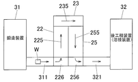
- a continuous heat treatment furnace as shown in FIG. 8 can also be employed.
- This continuous heat treatment furnace is disposed between a forging device 31 and a post-processing device 32 such as a welding device, and includes a solution treatment zone 22, a water tank zone 23, and an aging zone 25.
- the solution treatment zone 22 and the aging zone 25 are arranged in parallel, and in the solution treatment zone 22, the conveyance conveyor 225 for conveying the material W to be processed, and the aging zone 25
- the transport conveyor 255 that transports the workpiece W is arranged in parallel and in the opposite direction.
- the downstream side of the solution zone 22 and the upstream side of the aging zone 25 are arranged correspondingly, and the upstream side of the solution zone 22 and the downstream side of the aging zone 25 are arranged correspondingly. Yes.
- an upstream side (carrying-in port) of the water tank zone 23 is disposed corresponding to the downstream end of the solution zone 22, and a downstream side (discharge) of the water tank zone 23 corresponding to the upstream end of the aging zone 25.
- the material W to be processed that has been carried into the water tank zone 23 from the solution zone 22 passes through the water tank zone 23 by the conveyor 235 and is carried into the aging zone 25.
- the material W to be treated that has passed through the solution zone 22 is folded back (around the U-turn) around the water tank zone 23 and passes through the aging zone 25.
- the conveyor 235 in the water tank zone 23 can pass the material W to be processed into the water in the water tank, similarly to the continuous heat treatment furnace shown in FIG.
- the lengths of the solution treatment zone 22 and the aging zone 25 are increased. Will be different. However, the lengths of the solution zone 22 and the aging zone 25 can be matched by adjusting the conveyance speeds of the solution conveyors 225 and 255 in the solution zone 22 and the aging zone 25.
- a turntable 226 is disposed on the upstream side of the solution solution zone 22, and a conveyer 311 is disposed between the turntable 226 and the forging device 31. Accordingly, the workpiece W carried out from the forging device 31 is conveyed to the turntable 226 by the conveyer 311, rotated by the turntable 226, adjusted in direction, and then carried into the solution zone 22. It has become.
- a turntable 256 is disposed on the downstream side of the aging zone 25, and a conveyor conveyer 321 is disposed between the turntable 256 and the post-processing device 32. Therefore, the workpiece W carried out of the aging zone 25 is rotated by the turntable 256 and the direction thereof is adjusted, and then conveyed to the post-processing device 32 by the conveyance conveyor 321.
- each conveyor and turntable and the temperature of each heat treatment zone are controlled by a control device similar to the continuous heat treatment furnace of FIG.
- the material W to be processed as an Al forged member forged by the forging device 31 is carried into the solution zone 22 via the conveyor 311 and the turntable 226 and passes through the solution zone 22. Solution treatment.
- the to-be-processed material W carried into the water tank zone 23 from the solution zone 22 is quenched by passing through the water in the water tank.
- the material to be treated W introduced from the water tank zone 23 to the aging zone 25 passes through the aging zone 25 and is subjected to aging treatment.
- the material W to be processed is transported to the post-process device 32 by the turntable 256 and the transport conveyor 321 and subjected to a welding process or the like.
- solution treatment, quenching treatment, and aging treatment can be performed automatically and continuously as described above, and production efficiency can be improved.
- the solution treatment zone 22 and the aging zone 25 are arranged in parallel and the conveying direction is reversed, and the material W to be treated passing through the solution treatment zone 22 is in the peripheral portion of the water tank zone 23. It turns around and passes through the aging zone 25. For this reason, the outlet of the solution zone 22 (the inlet of the water tank zone 23) and the inlet of the aging zone 25 (the outlet of the water tank zone 23) are formed on one side wall (same wall surface) of the water tank zone 23. be able to. As a result, the solution zone 22, the aging zone 25, and the like can be arranged at arbitrary positions between the forging device 31 and the post-processing device (for example, a welding processing device) 32. Accordingly, the degree of freedom in design increases, and a production system (manufacturing apparatus) in which each zone is arranged at an optimal position can be constructed.
- a post-processing device welding processing device
- a continuous heat treatment furnace such as the heat treatment zones 22 and 25 from the process conveyor.
- a solution temperature increase zone, an aging temperature increase zone, an aging temperature decrease zone, and the like may be provided as necessary.
- a partition door may be provided between each of the plurality of zones.
- a molten Al alloy corresponding to each sample thus obtained was cast into a mold, and a disk sample 3 having a shape as shown in FIG. 3 was collected and analyzed by emission spectroscopic analysis described in JIS H 1305.
- s1 to s6 of the disk sample 3 are as follows. That is, s1 is 18 mm, s2 is 30 mm, s3 is 50 mm, s4 is 35 mm, s5 is 5 mm, and s6 is 5 mm.
- the ingot corresponding to each sample obtained in this way was subjected to peripheral cutting so as to have a diameter of 60 mm with a lathe, then cut to a standard length, and homogenized under the conditions shown in Table 2A.
- peripheral cutting so as to have a diameter of 60 mm with a lathe, then cut to a standard length, and homogenized under the conditions shown in Table 2A.
- the surface state was confirmed visually and the presence or absence of local melting was confirmed.
- the continuous casting round bar after the homogenization process was cut
- the pre-heated material was preheated under the conditions shown in Table 2A, and then installed to a thickness of 35 mm from the side of the round bar. Prior to upsetting, the surface condition was visually confirmed to check for local melting. In addition, after upsetting, the presence or absence of cracks on the sample surface was confirmed by a solvent-removable penetrant flaw detection test (color check). The subsequent upset (forged member) was held at the solution temperature shown in Table 2A for 3 hours, then quenched with water, and immediately after that, an aging treatment was performed under the conditions shown in Table 2A. About the sample after solution treatment, the surface state was confirmed visually and the presence or absence of local melting was confirmed.
- each sample after solution treatment a sample subjected to two-stage aging treatment was also prepared for comparison.
- each sample after the solution treatment is subjected to a first-stage aging treatment that is held at 110 ° C. for 6 hours, and then a second-stage aging treatment that is held at 150 ° C. for 8 hours, thereby performing a two-stage aging treatment.
- Each sample was also prepared.
- Example 10 is the same as Example 1 except that the ratio of the aging treatment time to the solution treatment time is described as described later.
- JIS14B proportional test pieces were collected from the obtained samples at the welded portion and the base metal portion, and the tensile strength [MPa] was measured.
- the Vickers hardness of the heat affected zone 15 during welding (see FIG. 4B) and the end portion not affected by heat (the other portion 16) is measured, and the Vickers hardness of the heat affected zone 15 during welding is measured.
- the value (ratio) divided by the Vickers hardness of the end portion 16 not affected by heat is 0.8 or more, it is judged that the hardness recovery performance of the heat affected zone 15 is “good”, 0.8 It was judged that the hardness recovery performance of the heat affected zone 15 was “bad (bad)”.
- a 2 mm ⁇ 4.3 mm ⁇ 42.4 mm test piece was cut out from the upset product (forged product sample), and the yield strength was measured using a three-point bending jig at the center of the 4.3 mm ⁇ 42.4 mm surface. A stress corresponding to 70% of the above was applied. During the load, the test piece and the jig were electrically insulated. As a corrosive solution, 36 g of chromium (IV) oxide, 30 g of potassium dichromate and 3 g of sodium chloride were dissolved per liter of pure water, and a solution maintained at 95 to 100 ° C. was prepared. After the test piece loaded with stress was immersed in the corrosive liquid for 16 hours, the appearance of the test piece was observed to confirm whether cracks were generated.
- chromium (IV) oxide, 30 g of potassium dichromate and 3 g of sodium chloride were dissolved per liter of pure water, and a solution maintained at 95 to 100 ° C. was prepared. After the
- Example 1 to 7, 11, and 12 satisfy all the requirements of the present invention, so that no ingot cracking, weld cracking, forging cracking, and local melting occur, and tensile strength
- the joint efficiency is excellent, and there is little difference in strength between the one-stage aging-treated product and the two-stage aging-treated product, and it can be seen that sufficient strength is obtained by one-step aging. Moreover, stress corrosion cracking did not occur.
- “joint efficiency” has the same meaning as the hardness recovery performance of the heat affected zone. Since Example 10 has substantially the same conditions as Example 1, the same result as Example 1 is obtained.
- the ratio of the aging treatment time to the solution treatment time is 1 to 6, and the solution treatment The time is not so different from the solution treatment time.
- Comparative Example 4 the Cu content was slightly lower and the Mg content was also lower. For the same reason as in Comparative Example 3, excellent tensile strength was not obtained with the one-stage aging product, and Thus, the strength of the one-stage aging product was significantly reduced.
- Example 1 to 4 related to the present invention there is no difference in strength (rate of change in strength) between the one-stage aging-treated product and the two-stage aging-treated product, and the preferred and sufficient strength (single-step aging treatment) 460 MPa or more, more preferably 500 MPa or more), and a practical product that does not cause cracking could be obtained.
- Comparative Examples 3 and 4 the difference in strength between the one-stage aging-treated product and the two-stage aging-treated product was large, and two-stage aging treatment was required in order to obtain a preferable sufficient strength.
- the sufficient and sufficient strength was obtained by the one-stage aging treatment, but cracking occurred and it was not practical, and the preferable and sufficient strength could not be obtained, so that it was not practical.
- Table 5 shows DAS ( ⁇ m) and average particle size ( ⁇ m) of the crystallized material in the Al alloy ingots (samples) of Examples 1 (10) to 7, 11, and 12.
- Al alloy having high strength, desired mechanical characteristics and stress corrosion cracking resistance performance without losing hardness recovery performance after welding can be obtained. Furthermore, an Al alloy product having the desired characteristics can be reliably and efficiently manufactured by a one-step aging treatment simplified in a short time of 130 to 170 ° C. ⁇ 8 to 12 Hr.
- the method for producing an Al alloy joined body of the present invention can be applied to a forging / welding technique for producing a high-quality Al alloy product.
Abstract
Disclosed is a method which is capable of efficiently producing a high-strength and lightweight Al alloy joined bodies. Specifically disclosed is a method for producing an Al alloy joined body, which comprises: a step of obtaining an Al alloy melt of an Al-Zn-Mg alloy that has a specific alloy composition; a step of obtaining an Al alloy ingot having a specific structure by continuously casting the Al alloy melt at a specific casting rate; a step of obtaining an Al alloy cast member by subjecting the Al alloy ingot to a specific homogenization treatment; a step of obtaining an Al alloy forged member by subjecting the Al alloy cast member to warm forging; a step of subjecting the Al alloy forged member to a solution heat treatment; a step of subjecting the Al alloy forged member after the solution heat treatment to a single-step aging treatment; and a step of obtaining an Al alloy joined body by welding the Al alloy forged member after the single-step aging treatment with a component to be joined, said component being formed from an Al alloy.
Description
本発明は、Al(アルミニウム)合金を溶接によって接合するようにしたAl合金接合体の製造方法およびその関連技術に関する。
The present invention relates to a method for manufacturing an Al alloy joined body in which an Al (aluminum) alloy is joined by welding, and a related technique.
Al-Zn-Mg系のAl合金は、強度、加工性等に優れるため、構造材として多く用いられている。
Al-Zn-Mg Al alloys are often used as structural materials because of their excellent strength and workability.
このようなAl-Zn-Mg系Al合金製の部材どうしを溶接すると、溶接部が溶接熱により再溶体化して一旦軟化するが、その後の自然時効により強度が回復することが知られている。そこで、構造材の中でも、溶接が必要でかつ高強度が求められる部材としては、Al-Zn-Mg系合金が一般に用いられてきた。
It is known that when such members made of Al—Zn—Mg-based Al alloy are welded together, the welded portion is re-solutionized by welding heat and temporarily softened, but the strength is recovered by subsequent natural aging. Therefore, among structural materials, Al—Zn—Mg alloys have been generally used as members that require welding and require high strength.
また、一般的なAl-Zn-Mg系合金においては、例えば下記特許文献1~3に示すように、焼入れ後、直ぐに人工時効するよりも、室温に24時間以上放置した後、人工時効した方が、引張強度および硬度が高くなり、応力腐食割れ性を向上させることが知られている。また、これらの人工時効条件についても、引張強度および硬度を向上させるために、80~130℃で1~16時間で一段目の時効処理を施した後、140~190℃で2~24時間で二段目の時効処理を行う、いわゆる二段時効の熱処理が施されている。
Further, in general Al—Zn—Mg-based alloys, for example, as shown in Patent Documents 1 to 3 below, after artificial quenching immediately after quenching, after being left at room temperature for 24 hours or more, artificial aging However, it is known that the tensile strength and hardness are increased and the stress corrosion cracking property is improved. Also, regarding these artificial aging conditions, in order to improve tensile strength and hardness, the first aging treatment is performed at 80 to 130 ° C. for 1 to 16 hours, and then at 140 to 190 ° C. for 2 to 24 hours. A so-called two-stage aging heat treatment is performed to perform the second-stage aging treatment.
近年、Al-Zn-Mg系合金が多く用いられている車両では運動性能および環境性能を向上させるために、軽量化が求められる上さらに、当該合金においては、溶接後の硬度回復性能を失うことなく、高い強度を確保できることが求められている。
In recent years, vehicles that use a lot of Al-Zn-Mg-based alloys are required to be lighter in order to improve motor performance and environmental performance, and in addition, these alloys lose their hardness recovery performance after welding. There is no need to ensure high strength.
その一方、Al合金の技術分野では、他の金属加工技術分野等と同様、生産性の向上が常に求められているが、Al-Zn-Mg系合金において、高強度および軽量化を図りつつ、生産性を向上させることは非常に困難である、という課題を抱えている。
On the other hand, in the technical field of Al alloys, as in other metal processing technical fields, etc., improvement in productivity is always required, but in Al-Zn-Mg based alloys, while achieving high strength and light weight, There is a problem that it is very difficult to improve productivity.
すなわち、上記特許文献1~3に示すように、従来のAl-Zn-Mg系合金において、十分な強度を確保するには、時効処理として、長時間で複雑な熱処理が必要であるため、生産性を向上させることが困難である、という課題があった。また熱処理の簡略化を図ろうとすると、十分な強度を得ることができず、増肉等による補強が必要となり、軽量化を図ることが困難である、という課題が発生する。
That is, as shown in Patent Documents 1 to 3 above, in order to secure sufficient strength in conventional Al—Zn—Mg alloys, complex heat treatment is required for a long time as an aging treatment. There is a problem that it is difficult to improve the performance. Further, when trying to simplify the heat treatment, there is a problem that sufficient strength cannot be obtained, reinforcement by thickening or the like is required, and it is difficult to reduce the weight.
本発明の好ましい実施形態は、関連技術における上述した及び/又は他の問題点に鑑みてなされたものである。本発明の好ましい実施形態は、既存の方法及び/又は装置を著しく向上させることができるものである。
The preferred embodiments of the present invention have been made in view of the above and / or other problems in the related art. Preferred embodiments of the present invention can significantly improve existing methods and / or apparatus.
この発明は、上記の課題に鑑みてなされたものであり、高強度で軽量なAl合金接合体を効率良く製造することができるAl合金接合体の製造方法およびその関連技術を提供することを目的とする。
The present invention has been made in view of the above problems, and an object of the present invention is to provide an Al alloy joined body manufacturing method and related technology capable of efficiently producing a high-strength and lightweight Al alloy joined body. And
本発明のその他の目的及び利点は、以下の好ましい実施形態から明らかであろう。
Other objects and advantages of the present invention will be apparent from the following preferred embodiments.
上記の目的を達成するため、本発明は、以下の構成を備えている。
In order to achieve the above object, the present invention has the following configuration.
[1]Fe:0.2~0.35質量%、Cu:0.1~0.4質量%、Mn:0.3~0.6質量%、Mg:2.0~2.5質量%、Zn:5.0~5.5質量%、Zr:0.1~0.2質量%、Ti:0.2質量%以下含有し、残部がAlおよび不可避不純物からなる合金組成を有するAl合金溶湯を得る工程と、
前記Al合金溶湯を、「最大鋳造速度(mm/min)≦-1.43×鋳造径(mm)+500」の条件を満たす鋳造速度で連続鋳造することによって、デンドライト2次アーム間隔(DAS)が40μm以下、かつ晶出物の平均粒径が8μm以下の組織を有するAl合金鋳塊を得る工程と、
前記Al合金鋳塊に対して、400~600℃の温度で1時間以上保持する均質化処理を施すことによって、Al合金鋳造部材を得る工程と、
前記Al合金鋳造部材に対して、熱間鍛造を行ってAl合金鍛造部材を得る工程と、
前記Al合金鍛造部材に対して、溶体化処理を施す工程と、
前記溶体化処理後のAl合金鍛造部材に対して、一段時効処理を施す工程と、
前記一段時効処理後のAl合金鍛造部材を、Al合金製の接合部品と溶接してAl合金接合体を得る工程と、を含むことを特徴とするAl合金接合体の製造方法。 [1] Fe: 0.2 to 0.35 mass%, Cu: 0.1 to 0.4 mass%, Mn: 0.3 to 0.6 mass%, Mg: 2.0 to 2.5 mass% Zn alloy: 5.0 to 5.5% by mass, Zr: 0.1 to 0.2% by mass, Ti: 0.2% by mass or less, Al alloy having an alloy composition in which the balance is made of Al and inevitable impurities Obtaining a molten metal;
By continuously casting the molten Al alloy at a casting speed that satisfies the condition of “maximum casting speed (mm / min) ≦ −1.43 × casting diameter (mm) +500”, the dendrite secondary arm spacing (DAS) is reduced. Obtaining an Al alloy ingot having a structure of 40 μm or less and a crystallite having an average particle size of 8 μm or less;
A step of obtaining an Al alloy cast member by subjecting the Al alloy ingot to a homogenization treatment of holding at a temperature of 400 to 600 ° C. for 1 hour or more;
For the Al alloy cast member, performing hot forging to obtain an Al alloy forged member;
A step of subjecting the Al alloy forged member to a solution treatment;
A step of performing a one-stage aging treatment on the Al alloy forged member after the solution treatment,
And a step of welding the Al alloy forged member after the one-stage aging treatment with an Al alloy joint component to obtain an Al alloy joined body.
ここで本発明において、鋳造速度とは、モールドから鋳塊を引っ張り出す速度で、単位時間当たりの鋳塊の移動速度を測定することによって得られる。鋳造時には、停止している状態から、徐々に速度を上げ、鋳造が安定した状態で最大速度となる。本発明においては、この最大速度を最大鋳造速度と称するものである。
Here, in the present invention, the casting speed is a speed at which the ingot is pulled from the mold, and is obtained by measuring the moving speed of the ingot per unit time. At the time of casting, the speed is gradually increased from the stopped state, and the maximum speed is reached when the casting is stable. In the present invention, this maximum speed is referred to as the maximum casting speed.
さらに本発明において、一段時効処理とは、比較的短時間での1回(1度)の時効処理を言う。本発明において、2回以上の時効処理を行う必要がなく、一段時効処理を行った後は、時効処理を行う必要がない。つまり本発明においては、鍛造部材に対し、一段時効処理を行った後は、二段目以降の時効処理を省略して、切削処理等の時効処理以外の次の処理を行うことができる。
Furthermore, in the present invention, the one-stage aging treatment refers to an aging treatment once (once) in a relatively short time. In the present invention, it is not necessary to perform the aging treatment twice or more, and it is not necessary to perform the aging treatment after the one-step aging treatment. That is, in the present invention, after the one-step aging treatment is performed on the forged member, the second-stage and subsequent aging treatments can be omitted, and the next treatment other than the aging treatment such as cutting treatment can be performed.
なお本発明の一段時効処理は、1回の時効処理であり、一段目の時効処理と二段目の時効処理との2回の時効処理を行う二段時効処理とは異なる。
The one-stage aging process of the present invention is a single aging process, and is different from the two-stage aging process in which the first-stage aging process and the second-stage aging process are performed twice.
さらに本発明の一段時効処理は、比較的短時間のものであり、長時間で複雑な一段時効処理、例えば24時間以上の長時間で複雑な温度制御を行う一段時効処理とも異なる。
Further, the one-step aging treatment of the present invention is a relatively short time, and is different from a one-step aging treatment in which a complicated one-step aging treatment is performed for a long time, for example, a complicated temperature control is performed for a long time of 24 hours or more.
また本発明においては、溶体化処理後、一段時効処理を行う前に、室温放置処理等を行うようにしても良いし、溶体化処理後、室温放置処理等を行わずに直ちに一段時効処理を行うようにしても良い。
Further, in the present invention, after the solution treatment, before the one-stage aging treatment, the room temperature treatment may be performed, or after the solution treatment, the one-step aging treatment is performed immediately without performing the room temperature treatment. You may make it do.
[2]前記一段時効処理を、130~170℃の温度で、溶体化処理時間の1~6倍の時間で行うようにした前項1に記載のAl合金接合体の製造方法。
[2] The method for producing an Al alloy joined body as recited in the aforementioned Item 1, wherein the one-stage aging treatment is performed at a temperature of 130 to 170 ° C. for 1 to 6 times the solution treatment time.
[3]前記熱間鍛造を、鍛造素材温度が350~500℃の温度で行うようにした前項1または2に記載のAl合金接合体の製造方法。
[3] The method for producing an Al alloy joined body according to item 1 or 2, wherein the hot forging is performed at a forging material temperature of 350 to 500 ° C.
[4]前記溶体化処理を、400~500℃の温度で行うようにした前項1~3のいずれか1項に記載のAl合金接合体の製造方法。
[4] The method for producing an Al alloy joined body according to any one of items 1 to 3, wherein the solution treatment is performed at a temperature of 400 to 500 ° C.
[5]前記接合部品として、前記時効処理後のAl合金鍛造部材と同じ構成の部材を用いるようにした前項1~4のいずれか1項に記載のAl合金接合体の製造方法。
[5] The method for producing an Al alloy joined body according to any one of the preceding items 1 to 4, wherein a member having the same configuration as the Al alloy forged member after the aging treatment is used as the joining component.
[6]「Znの質量%」/(「Mgの質量%」-α×「Cuの質量%」)=3、かつ
α=1~20の条件を満たすようにした前項1~5のいずれか1項に記載のAl合金接合体の製造方法。 [6] Any of the preceding items 1 to 5, wherein “mass% of Zn” / (“mass% of Mg” −α × “mass% of Cu”) = 3 and α = 1-20 are satisfied. 2. A method for producing an Al alloy joined body according to item 1.
α=1~20の条件を満たすようにした前項1~5のいずれか1項に記載のAl合金接合体の製造方法。 [6] Any of the preceding items 1 to 5, wherein “mass% of Zn” / (“mass% of Mg” −α × “mass% of Cu”) = 3 and α = 1-20 are satisfied. 2. A method for producing an Al alloy joined body according to item 1.
[7]前項1~6のいずれか1項に記載のAl合金接合体の製造方法に用いられるAl合金接合体の製造装置であって、
前記Al合金鍛造部材としての被処理材を搬送するための搬送手段と、
前記溶体化処理を施す工程を実施するための溶体化用熱処理ゾーンと、
前記一段時効処理を施す工程を実施するための一段時効用熱処理ゾーンと、を備え、
前記搬送手段の搬送によって、被処理材を溶体化用熱処理ゾーンおよび前記一段時効用熱処理ゾーンに順次通過させることにより、被処理材に対し溶体化処理および一段時効処理を順次実施するようにしたことを特徴とするAl合金接合体の製造装置。 [7] An apparatus for manufacturing an Al alloy joined body used in the method for producing an Al alloy joined body according to any one of [1] to [6],
Transport means for transporting the material to be processed as the Al alloy forged member;
A heat treatment zone for solution treatment for carrying out the step of performing the solution treatment;
A one-stage aging heat treatment zone for carrying out the step of performing the one-stage aging treatment,
By sequentially passing the material to be treated through the solution heat treatment zone and the one-stage aging heat treatment zone by the conveyance of the conveyance means, the solution treatment and the one-stage aging treatment are sequentially performed on the material to be treated. An apparatus for manufacturing an Al alloy joined body characterized by the above.
[8]前記溶体化用熱処理ゾーンおよび前記一段時効用熱処理ゾーン間に、水が貯留された焼き入れ処理用水槽を有する水槽ゾーンをさらに備え、
溶体化処理を行った後、一段時効処理を行う前に、被処理材を前記水槽ゾーンの水槽内を通過させて、焼き入れ処理を実施するようにした前項7に記載のAl合金接合体の製造装置。 [8] A water tank zone further comprising a quenching water tank in which water is stored between the solution heat treatment zone and the one-stage aging heat treatment zone,
After performing the solution treatment, before performing the one-stage aging treatment, the material to be treated is passed through the water tank of the water tank zone and the quenching process is performed. Manufacturing equipment.
[9]前記溶体化用熱処理ゾーンおよび前記一段時効用熱処理ゾーンが並列に、かつ被処理材の搬送方向が互いに逆向きに配置されるとともに、
前記溶体化用熱処理ゾーンの搬出側端部と、前記一段時効用熱処理ゾーンの搬入側端部とが対応して配置され、
前記溶体化用熱処理ゾーン、前記水槽ゾーンおよび前記一段時効用熱処理ゾーンを通過する被処理材が前記水槽ゾーンの周辺部で折り返して搬送されるようになっている前項8に記載のAl合金接合体の製造装置。 [9] The solution heat treatment zone and the one-stage aging heat treatment zone are arranged in parallel, and the conveying direction of the material to be treated is opposite to each other,
The carry-out side end of the solution heat treatment zone and the carry-in side end of the one-stage aging heat treatment zone are arranged correspondingly,
9. The Al alloy joined body according toitem 8 above, wherein the material to be treated that passes through the solution heat treatment zone, the water tank zone, and the one-stage aging heat treatment zone is folded and conveyed at the periphery of the water tank zone. Manufacturing equipment.
前記溶体化用熱処理ゾーンの搬出側端部と、前記一段時効用熱処理ゾーンの搬入側端部とが対応して配置され、
前記溶体化用熱処理ゾーン、前記水槽ゾーンおよび前記一段時効用熱処理ゾーンを通過する被処理材が前記水槽ゾーンの周辺部で折り返して搬送されるようになっている前項8に記載のAl合金接合体の製造装置。 [9] The solution heat treatment zone and the one-stage aging heat treatment zone are arranged in parallel, and the conveying direction of the material to be treated is opposite to each other,
The carry-out side end of the solution heat treatment zone and the carry-in side end of the one-stage aging heat treatment zone are arranged correspondingly,
9. The Al alloy joined body according to
[10]Fe:0.2~0.35質量%、Cu:0.1~0.4質量%、Mn:0.3~0.6質量%、Mg:2.0~2.5質量%、Zn:5.0~5.5質量%、Zr:0.1~0.2質量%、Ti:0.2質量%以下含有し、残部がAlおよび不可避不純物からなる合金組成を有するAl合金溶湯を得る工程と、
前記Al合金溶湯を、「最大鋳造速度(mm/min)≦-1.43×鋳造径(mm)+500」の条件を満たす鋳造速度で連続鋳造することによって、デンドライト2次アーム間隔(DAS)が40μm以下、かつ晶出物の平均粒径が8μm以下の組織を有するAl合金鋳塊を得る工程と、
前記Al合金鋳塊に対して、400~600℃の温度に1時間以上保持する均質化処理を施すことによって、Al合金鋳造部材を得る工程と、を含むことを特徴とする溶接用Al合金鋳造部材の製造方法。 [10] Fe: 0.2 to 0.35 mass%, Cu: 0.1 to 0.4 mass%, Mn: 0.3 to 0.6 mass%, Mg: 2.0 to 2.5 mass% Zn alloy: 5.0 to 5.5% by mass, Zr: 0.1 to 0.2% by mass, Ti: 0.2% by mass or less, Al alloy having an alloy composition in which the balance is made of Al and inevitable impurities Obtaining a molten metal;
By continuously casting the molten Al alloy at a casting speed that satisfies the condition of “maximum casting speed (mm / min) ≦ −1.43 × casting diameter (mm) +500”, the dendrite secondary arm spacing (DAS) is reduced. Obtaining an Al alloy ingot having a structure of 40 μm or less and a crystallite having an average particle size of 8 μm or less;
And a step of obtaining an Al alloy cast member by subjecting the Al alloy ingot to a homogenization treatment of holding at a temperature of 400 to 600 ° C. for 1 hour or longer. Manufacturing method of member.
[11]前記Al合金溶湯を準備するのに先立って、そのAl合金溶湯におけるFe、Cu、Mn、Mg、Zn、Zr、Tiの各含有量を仮設値に設定する第1準備工程と、
前記Al合金鋳造部材を鍛造加工して得られるAl合金鍛造部材における目標とする特性を設定する第2準備工程と、
前記仮設値を基にして得られた試作のAl合金溶湯に対し、前記Al合金鋳塊を得る工程に準拠した工程と、前記Al合金鋳造部材を得る工程に準拠した工程と、を順次行って、試作のAl合金鋳造部材を得るとともに、その試作のAl合金鋳造部材に対し、熱間鍛造を行って試作のAl合金鍛造部材を得る第3準備工程と、
試作のAl合金鍛造部材から求められた実際の特性を、前記目標とする特性と比較し、その比較結果を基に、前記仮設値を変更する第4準備工程と、を含み、
前記第3および第4準備工程を繰り返し行って、実際に使用するAl合金溶湯を準備するようにした前項10に記載のAl合金鋳造部材の製造方法。 [11] Prior to preparing the Al alloy molten metal, a first preparation step of setting each content of Fe, Cu, Mn, Mg, Zn, Zr, Ti in the Al alloy molten metal to a temporary value;
A second preparation step for setting a target characteristic in the Al alloy forged member obtained by forging the Al alloy cast member;
For the experimental Al alloy melt obtained based on the temporary value, a step based on the step of obtaining the Al alloy ingot and a step based on the step of obtaining the Al alloy cast member were sequentially performed. The third preparatory step for obtaining a prototype Al alloy forged member by performing hot forging on the prototype Al alloy cast member while obtaining a prototype Al alloy cast member;
The actual characteristics obtained from the prototype Al alloy forged member are compared with the target characteristics, and based on the comparison result, the fourth preparation step of changing the temporary value,
11. The method for producing an Al alloy cast member according toitem 10, wherein the third and fourth preparation steps are repeatedly performed to prepare an Al alloy molten metal to be actually used.
前記Al合金鋳造部材を鍛造加工して得られるAl合金鍛造部材における目標とする特性を設定する第2準備工程と、
前記仮設値を基にして得られた試作のAl合金溶湯に対し、前記Al合金鋳塊を得る工程に準拠した工程と、前記Al合金鋳造部材を得る工程に準拠した工程と、を順次行って、試作のAl合金鋳造部材を得るとともに、その試作のAl合金鋳造部材に対し、熱間鍛造を行って試作のAl合金鍛造部材を得る第3準備工程と、
試作のAl合金鍛造部材から求められた実際の特性を、前記目標とする特性と比較し、その比較結果を基に、前記仮設値を変更する第4準備工程と、を含み、
前記第3および第4準備工程を繰り返し行って、実際に使用するAl合金溶湯を準備するようにした前項10に記載のAl合金鋳造部材の製造方法。 [11] Prior to preparing the Al alloy molten metal, a first preparation step of setting each content of Fe, Cu, Mn, Mg, Zn, Zr, Ti in the Al alloy molten metal to a temporary value;
A second preparation step for setting a target characteristic in the Al alloy forged member obtained by forging the Al alloy cast member;
For the experimental Al alloy melt obtained based on the temporary value, a step based on the step of obtaining the Al alloy ingot and a step based on the step of obtaining the Al alloy cast member were sequentially performed. The third preparatory step for obtaining a prototype Al alloy forged member by performing hot forging on the prototype Al alloy cast member while obtaining a prototype Al alloy cast member;
The actual characteristics obtained from the prototype Al alloy forged member are compared with the target characteristics, and based on the comparison result, the fourth preparation step of changing the temporary value,
11. The method for producing an Al alloy cast member according to
[12]Fe:0.2~0.35質量%、Cu:0.1~0.4質量%、Mn:0.3~0.6質量%、Mg:2.0~2.5質量%、Zn:5.0~5.5質量%、Zr:0.1~0.2質量%、Ti:0.2質量%以下含有し、残部がAlおよび不可避不純物からなる合金組成を有するAl合金溶湯を得る工程と、
前記Al合金溶湯を、「最大鋳造速度(mm/min)≦-1.43×鋳造径(mm)+500」の条件を満たす鋳造速度で連続鋳造することによって、デンドライト2次アーム間隔(DAS)が40μm以下、かつ晶出物の平均粒径が8μm以下の組織を有するAl合金鋳塊を得る工程と、
前記Al合金鋳塊に対して、400~600℃の温度に1時間以上保持する均質化処理を施すことによって、Al合金鋳造部材を得る工程と、
前記Al合金鋳造部材に対して、熱間鍛造を行ってAl合金鍛造部材を得る工程と、
前記Al合金鍛造部材に対して、溶体化処理を施す工程と、
溶体化処理後のAl合金鍛造部材に対して、一段時効処理を施す工程と、を含むことを特徴とする溶接用Al合金鍛造部材の製造方法。 [12] Fe: 0.2 to 0.35 mass%, Cu: 0.1 to 0.4 mass%, Mn: 0.3 to 0.6 mass%, Mg: 2.0 to 2.5 mass% Zn alloy: 5.0 to 5.5% by mass, Zr: 0.1 to 0.2% by mass, Ti: 0.2% by mass or less, Al alloy having an alloy composition in which the balance is made of Al and inevitable impurities Obtaining a molten metal;
By continuously casting the molten Al alloy at a casting speed that satisfies the condition of “maximum casting speed (mm / min) ≦ −1.43 × casting diameter (mm) +500”, the dendrite secondary arm spacing (DAS) is reduced. Obtaining an Al alloy ingot having a structure of 40 μm or less and a crystallite having an average particle size of 8 μm or less;
A step of obtaining an Al alloy cast member by subjecting the Al alloy ingot to a homogenization treatment for holding at a temperature of 400 to 600 ° C. for 1 hour or more;
For the Al alloy cast member, performing hot forging to obtain an Al alloy forged member;
A step of subjecting the Al alloy forged member to a solution treatment;
And a step of subjecting the Al alloy forged member after solution treatment to a one-step aging treatment.
[13]前記Al合金溶湯を準備するのに先立って、そのAl合金溶湯におけるFe、Cu、Mn、Mg、Zn、Zr、Tiの各含有量を仮設値に設定する第1準備工程と、
製造予定の前記Al合金鍛造部材における目標とする特性を設定する第2準備工程と、
前記仮設値を基にして得られた試作のAl合金溶湯に対し、前記Al合金鋳塊を得る工程に準拠した工程と、前記Al合金鋳造部材を得る工程に準拠した工程と、前記Al合金鍛造部材を得る工程に準拠した工程と、前記溶体化処理を施す工程に準拠した工程と、前記一段時効処理を施す工程に準拠した工程と、を順次行って、試作のAl合金鍛造部材を得る第3準備工程と、
試作のAl合金鍛造部材から求められた実際の特性を、前記目標とする特性と比較し、その比較結果を基に、前記仮設値を変更する第4準備工程と、を含み、
前記第3および第4準備工程を繰り返し行って、実際に使用するAl合金溶湯を準備するようにした前項12に記載の溶接用Al合金鍛造部材の製造方法。 [13] Prior to preparing the molten Al alloy, a first preparation step of setting the contents of Fe, Cu, Mn, Mg, Zn, Zr, Ti in the molten Al alloy to temporary values;
A second preparation step for setting target characteristics in the Al alloy forged member to be manufactured;
For a prototype Al alloy melt obtained based on the temporary value, a step based on the step of obtaining the Al alloy ingot, a step based on the step of obtaining the Al alloy cast member, and the Al alloy forging A step in accordance with the step of obtaining a member, a step in accordance with the step of performing the solution treatment, and a step in accordance with the step of performing the one-stage aging treatment are sequentially performed to obtain a prototype Al alloy forged member. 3 preparation steps,
The actual characteristics obtained from the prototype Al alloy forged member are compared with the target characteristics, and based on the comparison result, the fourth preparation step of changing the temporary value,
13. The method for producing an Al alloy forged member for welding according toitem 12, wherein the third and fourth preparation steps are repeatedly performed to prepare an Al alloy molten metal to be actually used.
製造予定の前記Al合金鍛造部材における目標とする特性を設定する第2準備工程と、
前記仮設値を基にして得られた試作のAl合金溶湯に対し、前記Al合金鋳塊を得る工程に準拠した工程と、前記Al合金鋳造部材を得る工程に準拠した工程と、前記Al合金鍛造部材を得る工程に準拠した工程と、前記溶体化処理を施す工程に準拠した工程と、前記一段時効処理を施す工程に準拠した工程と、を順次行って、試作のAl合金鍛造部材を得る第3準備工程と、
試作のAl合金鍛造部材から求められた実際の特性を、前記目標とする特性と比較し、その比較結果を基に、前記仮設値を変更する第4準備工程と、を含み、
前記第3および第4準備工程を繰り返し行って、実際に使用するAl合金溶湯を準備するようにした前項12に記載の溶接用Al合金鍛造部材の製造方法。 [13] Prior to preparing the molten Al alloy, a first preparation step of setting the contents of Fe, Cu, Mn, Mg, Zn, Zr, Ti in the molten Al alloy to temporary values;
A second preparation step for setting target characteristics in the Al alloy forged member to be manufactured;
For a prototype Al alloy melt obtained based on the temporary value, a step based on the step of obtaining the Al alloy ingot, a step based on the step of obtaining the Al alloy cast member, and the Al alloy forging A step in accordance with the step of obtaining a member, a step in accordance with the step of performing the solution treatment, and a step in accordance with the step of performing the one-stage aging treatment are sequentially performed to obtain a prototype Al alloy forged member. 3 preparation steps,
The actual characteristics obtained from the prototype Al alloy forged member are compared with the target characteristics, and based on the comparison result, the fourth preparation step of changing the temporary value,
13. The method for producing an Al alloy forged member for welding according to
[14]前記第2準備工程において、前記一時時効処理における目標とする時効時間を予め設定し、
前記第3準備工程において、実際の時効時間を測定し、
前記第4準備工程において、実際の時効時間を、前記目標とする時効時間と比較し、その比較結果を基に、前記仮設値を変更するようにした前項13に記載の溶接用Al合金鍛造部材の製造方法。 [14] In the second preparation step, a target aging time in the temporary aging treatment is set in advance,
In the third preparation step, the actual aging time is measured,
In the fourth preparation step, the actual aging time is compared with the target aging time, and the temporary value is changed based on the comparison result. Manufacturing method.
[15]複数のAl合金製の接合部品が溶接されて、接合部品間の溶接部に、溶接による肉盛り部が設けられるとともに、その肉盛り部の近傍に、溶接による熱の影響が及ぶ熱影響部が設けられたAl合金接合体であって、
前記複数の接合部品のうち、少なくとも1つ以上の接合部品が、Fe:0.2~0.35質量%、Cu:0.1~0.4質量%、Mn:0.3~0.6質量%、Mg:2.0~2.5質量%、Zn:5.0~5.5質量%、Zr:0.1~0.2質量%、Ti:0.2質量%以下含有し、残部がAlおよび不可避不純物からなる合金組成を有し、
前記熱影響部の硬度を「V1」、溶接による熱の影響が及ばない部位の平均硬度を「V2」として、「V1/V2≧0.8」の関係が成立するように構成されたことを特徴とするAl合金接合体。 [15] A plurality of joined parts made of an Al alloy are welded, and a welded portion is provided at a welded portion between the joined parts, and heat that is affected by heat in the vicinity of the welded portion is exerted. An Al alloy joined body provided with an affected part,
Among the plurality of joined parts, at least one joined part is Fe: 0.2 to 0.35 mass%, Cu: 0.1 to 0.4 mass%, Mn: 0.3 to 0.6 Wt%, Mg: 2.0-2.5 wt%, Zn: 5.0-5.5 wt%, Zr: 0.1-0.2 wt%, Ti: 0.2 wt% or less, The balance has an alloy composition consisting of Al and inevitable impurities,
The relationship of “V 1 / V 2 ≧ 0.8” is established, where the hardness of the heat affected zone is “V 1 ” and the average hardness of the portion not affected by the heat caused by welding is “V 2 ”. An Al alloy joined body characterized by the above.
発明[1]のAl合金接合体の製造方法によれば、溶接後の硬度回復性能を失わずに、強度が高く、所望の機械的特性および耐腐食性能を備えたAl合金鍛造製品を得ることができる。しかも、一段時効処理は、短時間で簡略化することができるため、上記所望の特性を備えたAl合金接合体を効率良く製造することができる。
According to the method for producing an Al alloy joined body of the invention [1], an Al alloy forged product having high strength, desired mechanical characteristics and corrosion resistance performance can be obtained without losing hardness recovery performance after welding. Can do. Moreover, since the one-step aging treatment can be simplified in a short time, an Al alloy joined body having the desired characteristics can be efficiently produced.
さらに溶接部の硬度低下が少ないため、Al合金接合体の全域で耐えることができる荷重も大きくなり、Al合金接合体の重量を低減できて、軽量化を図ることができる。
Furthermore, since there is little decrease in the hardness of the welded portion, the load that can be withstood in the entire area of the Al alloy joined body is increased, the weight of the Al alloy joined body can be reduced, and the weight can be reduced.
ここで、本発明において「溶接後の硬度回復性能」とは、T6処理を行った母材のヴィッカース硬度に対する、溶接による熱影響部のヴィッカース硬度の低下率のことを示し、具体的には、この低下率が20%以下であるとき、溶接後の硬度回復性能が良好である、と判断している。
Here, in the present invention, “hardness recovery performance after welding” refers to the decrease rate of the Vickers hardness of the heat-affected zone by welding with respect to the Vickers hardness of the base material subjected to T6 treatment, specifically, When the decrease rate is 20% or less, it is judged that the hardness recovery performance after welding is good.
本発明において、「溶接後の硬度回復性能」は以下の関係式で定義することができる。
In the present invention, “hardness recovery performance after welding” can be defined by the following relational expression.
「溶接後の硬度回復性能」=(「母材のヴィッカース硬度」-「熱影響部のヴィッカース硬度」)/「母材のヴィッカース硬度」
さらに本発明では、引張強度が450MPa以上であったものを「強度が高い」と判断している。 "Hardness recovery performance after welding" = ("Vickers hardness of base material"-"Vickers hardness of heat affected zone") / "Vickers hardness of base material"
Further, in the present invention, a material having a tensile strength of 450 MPa or more is determined as “high strength”.
なお、本発明において、ヴィッカース硬度は、JIS Z 2244に準拠するものである。さらに引張強度は、JIS Z 2201およびJIS Z 2241に準拠するものである。
In the present invention, the Vickers hardness is based on JIS Z 2244. Furthermore, the tensile strength conforms to JIS Z 2201 and JIS Z 2241.
発明[2]のAl合金接合体の製造方法によれば、時効処理を確実に行うことができるとともに、生産効率をより確実に向上させることができる。
According to the method for producing an Al alloy joined body of the invention [2], the aging treatment can be reliably performed and the production efficiency can be more reliably improved.
発明[3]のAl合金接合体の製造方法によれば、鍛造加工を精度良く行うことができる。
According to the method for producing an Al alloy joined body of the invention [3], forging can be performed with high accuracy.
発明[4]~[6]のAl合金接合体の製造方法によれば、より一層機械的強度に優れたAl合金接合体を得ることができる。
According to the method for producing an Al alloy joined body of the inventions [4] to [6], an Al alloy joined body having further excellent mechanical strength can be obtained.
発明[7]~[9]のAl合金接合体の製造装置によれば、上記所望の特性を備えたAl合金接合体をより一層効率良く製造することができる。
According to the apparatus for producing an Al alloy joined body of the inventions [7] to [9], an Al alloy joined body having the desired characteristics can be produced more efficiently.
発明[10]の溶接用Al合金鋳造部材の製造方法によれば、溶接用のAl合金製接合部品として最適なAl合金鋳造部材を製造することができる。
According to the method for producing an Al alloy cast member for welding according to the invention [10], an Al alloy cast member optimum as an Al alloy joint part for welding can be produced.
発明[11]のAl合金鋳造部材の製造方法によれば、所望のAl合金溶湯を準備でき、高品質のAl合金鋳造部材を得ることができる。
According to the method for producing an Al alloy cast member of the invention [11], a desired Al alloy molten metal can be prepared and a high quality Al alloy cast member can be obtained.
発明[12]の溶接用Al合金鍛造部材の製造方法によれば、溶接用のAl合金製接合部品として最適なAl合金鍛造部材を製造することができる。
According to the method for producing an Al alloy forged member for welding according to the invention [12], an Al alloy forged member optimum as an Al alloy joined part for welding can be produced.
発明[13][14]の溶接用Al合金鍛造部材の製造方法によれば、所望のAl合金溶湯を準備でき、高品質のAl合金鍛造部材を得ることができる。
According to the method for producing an Al alloy forged member for welding of the inventions [13] and [14], a desired molten Al alloy can be prepared, and a high quality Al alloy forged member can be obtained.
発明[15]のAl合金接合体は、溶接部の硬度低下が少ないため、所望の機械的特性および耐腐食性を確保しつつ、全体の重量を軽減することができる。
In the Al alloy joined body of the invention [15], since the hardness reduction of the welded portion is small, the overall weight can be reduced while ensuring the desired mechanical properties and corrosion resistance.
図1はこの発明の実施形態であるAl合金接合体の製造方法の一例を説明するためのフローチャートである。
FIG. 1 is a flowchart for explaining an example of a method for producing an Al alloy joined body according to an embodiment of the present invention.
同図に示すように、所定の合金組成を有するAl合金溶湯を準備し、そのAl合金溶湯を用いて、所定の条件下で連続鋳造することによって、Al合金鋳塊を得る。続いてAl合金鋳塊に対して、均質化処理を施して、Al合金鋳造部材を得る。その後、Al合金鋳造部材に対して、熱間鍛造加工を施して、Al合金鍛造部材を得る。さらにそのAl合金鍛造部材に対し、溶体化処理を施した後、一段時効処理を施す。その後、時効処理(二段目以降の時効処理)を行わずに、一段時効処理後のAl合金鍛造部材どうしを溶接処理によって接合一体化して、本実施形態のAl合金製品をなすAl合金接合体を得るものである。
As shown in the figure, an Al alloy molten metal having a predetermined alloy composition is prepared, and an Al alloy ingot is obtained by continuously casting the Al alloy molten metal under predetermined conditions. Subsequently, the Al alloy ingot is homogenized to obtain an Al alloy cast member. Thereafter, hot forging is performed on the Al alloy cast member to obtain an Al alloy forged member. Further, the Al alloy forged member is subjected to a solution treatment and then subjected to a one-stage aging treatment. Then, without performing the aging treatment (second-stage aging treatment), the Al alloy forged members obtained by joining and integrating the Al alloy forged members after the first-stage aging treatment by welding treatment to form the Al alloy product of the present embodiment Is what you get.
以下、本実施形態のAl合金接合体の製造方法について、製造手順に従って詳細に説明する。
Hereinafter, the manufacturing method of the Al alloy joined body of the present embodiment will be described in detail according to the manufacturing procedure.
本発明に用いられるAl鋳造素材としてのAl合金溶湯は、Feを0.2~0.35質量%、Cuを0.1~0.4質量%、Mnを0.3~0.6質量%、Mgを2.0~2.5質量%、Znを5.0~5.5質量%、Zrを0.1~0.2質量%、Tiを0.2質量%以下含有し、残部がAlおよび不可避不純物からなる合金組成を有している。
The molten Al alloy as an Al casting material used in the present invention is 0.2 to 0.35 mass% Fe, 0.1 to 0.4 mass% Cu, and 0.3 to 0.6 mass% Mn. Mg, 2.0 to 2.5 mass%, Zn 5.0 to 5.5 mass%, Zr 0.1 to 0.2 mass%, Ti 0.2 mass% or less, the balance being It has an alloy composition consisting of Al and inevitable impurities.
本発明における合金組成のうち、Feは、鋳造時の鋳塊割れや溶接時の溶接割れを抑制し、粗大再結晶を抑制する元素であり、本発明においては、Feの含有率(濃度)を0.2~0.35質量%に調整する必要がある。好ましくはFeの含有率を0.30~0.35質量%)に調整するのが良い。
Among the alloy compositions in the present invention, Fe is an element that suppresses ingot cracking during casting and weld cracking during welding and suppresses coarse recrystallization. In the present invention, the Fe content (concentration) is It is necessary to adjust to 0.2 to 0.35 mass%. Preferably, the Fe content is adjusted to 0.30 to 0.35 mass%.
Feの含有率が0.2質量%未満の場合には、上記の効果を十分に得ることができず、逆に0.35質量%を超える場合には、Al-Fe-Mn系の粗大晶出物が増加し、鍛造時の塑性加工性を阻害し、また、鍛造加工後の鍛造部材によって構成されるAl合金製品が最終的に車体等に組み付けられた際に、そのAl合金製品(組付部品)における伸性(延性)、靭性、疲労強度および衝撃特性が低下するおそれがあるので、望ましくない。
When the Fe content is less than 0.2% by mass, the above effect cannot be obtained sufficiently. On the other hand, when it exceeds 0.35% by mass, Al—Fe—Mn coarse crystals When the Al alloy product composed of forged parts after forging is finally assembled to the body, etc., the Al alloy product (assembly) This is not desirable because the ductility (ductility), toughness, fatigue strength, and impact characteristics of the attached part may be reduced.
Cuは、アルミニウムマトリックスに固溶して、固溶体中の溶質の過飽和度を上げるだけではなく、Mgと共存することで、Al-Cu-Mg金属間化合物を析出させることで、強度を付与する元素である。
Cu not only increases the degree of supersaturation of the solute in the solid solution by dissolving in the aluminum matrix, but also coexists with Mg, thereby precipitating an Al—Cu—Mg intermetallic compound to impart strength. It is.
また、本発明において、Cuは、Mgと共存させ、Mgとの共存状態を制御することにより、Al合金における時効処理によるAl-Cu-Mg系金属間化合物の析出状態が微細緻密となるようにその析出の挙動を適切に変化させることができる。つまり、Cuは、従来施していた、80~130℃で1~16時間の一段目の時効処理を施した後に140~190℃で2~24時間の二段目の時効を行う二段時効処理によって得られていた機械的特性および耐腐食性能と同等の性能を、130~170℃で比較的短時間で1回の時効処理(一段時効処理)を施すだけで得ることを可能とするために必要な元素である。ここで比較的短時間とは、例えば8~12時間、好ましくは8時間程度である。
In the present invention, Cu coexists with Mg, and the coexistence state with Mg is controlled so that the precipitation state of the Al—Cu—Mg intermetallic compound by aging treatment in the Al alloy becomes fine and dense. The behavior of the precipitation can be changed appropriately. In other words, Cu is a conventional two-stage aging treatment in which the second aging is performed at 140 to 190 ° C. for 2 to 24 hours after the first aging treatment at 80 to 130 ° C. for 1 to 16 hours. In order to obtain the same mechanical properties and corrosion resistance performance obtained by the above-mentioned, it is possible to obtain a single aging treatment (one-step aging treatment) at 130 to 170 ° C. in a relatively short time. Necessary element. Here, the relatively short time is, for example, 8 to 12 hours, preferably about 8 hours.
そのメカニズムは以下のように推定される。
The mechanism is estimated as follows.
すなわち、従来の通常のAl-Zn-Mg系合金においては、時効処理温度を高くしてしまうと、時効の初期にMg-Zn系金属間化合物がAlマトリックス内に粗大に析出してしまうために析出密度が粗くなってしまい、その後時効処理を継続しても析出密度が粗いままとなってしまう。このため、時効効果が充分に得られず、硬度の最大値が低くなってしまう。そこで、従来では、時効の初期の温度を低くして、Mg-Zn系金属間化合物をAlマトリックス内に微細に析出させ、その後の高温時効処理または長時間低温時効処理によって硬度上昇に寄与するサイズへと析出物を成長させることで、硬度の最大値を上昇させるようにしている。従って、時効処理としては、低温短時間と、高温短時間との2段階の時効処理もしくは、低温長時間の一段階の時効処理を用いざるを得なかった。従って、従来では、この時効処理に多大な時間と複雑な温度制御が必要となり、生産性の低下を来す要因となっていた。
That is, in the conventional ordinary Al—Zn—Mg alloy, if the aging treatment temperature is increased, the Mg—Zn intermetallic compound is coarsely precipitated in the Al matrix at the initial stage of aging. The precipitation density becomes coarse, and the precipitation density remains rough even if the aging treatment is continued thereafter. For this reason, the aging effect is not sufficiently obtained, and the maximum value of the hardness is lowered. Therefore, in the past, the size at which the initial temperature of aging is lowered and the Mg—Zn-based intermetallic compound is finely precipitated in the Al matrix and then contributes to the increase in hardness by high-temperature aging treatment or long-term low-temperature aging treatment. The maximum value of hardness is raised by growing precipitates. Therefore, as the aging treatment, a two-stage aging treatment of a low temperature short time and a high temperature short time or a one-step aging treatment of a low temperature and a long time must be used. Therefore, conventionally, this aging treatment requires a lot of time and complicated temperature control, which has been a factor in reducing productivity.
これに対して、本発明では、Cuを特定の範囲で添加している。これにより、時効処理を高温で行っても、時効の初期段階で、Al-Cu-Mg系金属間化合物をAlマトリックス内に微細にかつ高密度で析出させることができ、その後、Zn-Mg系金属間化合物が、微細に析出したAl-Cu-Mg系金属間化合物の上に析出することとなる。その結果、強度に寄与するまでの大きさに成長したZn-Mg系金属間化合物がAlマトリックス内に微細かつ緻密に存在し、硬度の最大値を十分に上昇させることが可能となる。
In contrast, in the present invention, Cu is added within a specific range. As a result, even if the aging treatment is performed at a high temperature, the Al—Cu—Mg intermetallic compound can be finely and densely precipitated in the Al matrix at the initial stage of aging, and then Zn—Mg The intermetallic compound is deposited on the finely precipitated Al—Cu—Mg intermetallic compound. As a result, Zn—Mg-based intermetallic compounds grown to a size that contributes to strength are finely and densely present in the Al matrix, and the maximum value of hardness can be sufficiently increased.
本発明においては、Cuの含有率(濃度)を0.1~0.4質量%に調整する必要があり、より好ましくは0.30~0.40質量%に調整するのが良い。Cuの含有量が0.1質量%未満の場合には、上記の効果を十分に得ることができず、また、時効初期に生成させるAl-Cu-Mg系金属間化合物の量が少な過ぎるため、一段時効処理では強度向上効果を確実に得ることができず、二段時効処理が必要となるので望ましくない。逆にCuの含有率が0.4質量%を超える場合には、強度は向上するものの、耐応力腐食割れ性が著しく低下し、溶接割れを発生させる危険性が生じるので望ましくない。
In the present invention, it is necessary to adjust the Cu content (concentration) to 0.1 to 0.4 mass%, more preferably 0.30 to 0.40 mass%. When the Cu content is less than 0.1% by mass, the above effect cannot be obtained sufficiently, and the amount of the Al—Cu—Mg intermetallic compound generated at the early stage of aging is too small. The one-stage aging treatment is not desirable because the strength improvement effect cannot be obtained with certainty and a two-stage aging treatment is required. Conversely, if the Cu content exceeds 0.4% by mass, the strength is improved, but the stress corrosion cracking resistance is remarkably lowered and there is a risk of generating weld cracks, which is not desirable.
本発明において、Mnは、粗大再結晶を抑制する元素である。本実施形態では、Mnの含有率(濃度)を0.3~0.6質量%に調整する必要があり、好ましくは0.5~0.6質量%に調整するのが良い。
In the present invention, Mn is an element that suppresses coarse recrystallization. In this embodiment, it is necessary to adjust the Mn content (concentration) to 0.3 to 0.6% by mass, and preferably to 0.5 to 0.6% by mass.
Mnの含有率が0.3質量%未満の場合には、粗大再結晶の抑制効果が小さくなる。逆に、Mnの含有率が0.6質量%を超える場合には、Al-Fe-Mn系の粗大晶出物が増加して、鍛造時の塑性加工性を阻害してしまい、また、鍛造加工後のAl合金製品が、最終的に車体等に組み付けられた際に、そのAl合金製品(組付部品)における伸性、靭性、疲労強度が低下するおそれがあるので望ましくない。
When the Mn content is less than 0.3% by mass, the effect of suppressing coarse recrystallization is reduced. On the other hand, when the Mn content exceeds 0.6% by mass, the Al—Fe—Mn-based coarse crystallized product increases, which impairs the plastic workability during forging. When the processed Al alloy product is finally assembled to a vehicle body or the like, the ductility, toughness, and fatigue strength of the Al alloy product (assembled part) may be reduced.
Mgは、Znと共存することにより、MgZn2金属間化合物(η相)を析出させて機械的強度を向上させる元素である。さらに、前述したように、Mgは、Cuと共存することで、時効初期におけるAl-Cu-Mg系金属間化合物の析出挙動を適切に変化させることができる。従って、Mgは、従来施していた、80~130℃で1~16時間の一段目の時効処理を施した後に140~190℃で2~24時間の二段目の時効処理を行う二段時効処理によって得られていた機械的特性および耐腐食性能と同等の性能を、130~170℃で比較的短時間の1回の時効処理(一段時効処理)を施すだけで得ることを可能とするために必要な元素である。ここで比較的短時間とは、例えば8~12時間、好ましくは8時間程度である。
Mg is an element that precipitates MgZn 2 intermetallic compound (η phase) and improves mechanical strength by coexisting with Zn. Furthermore, as described above, Mg can appropriately change the precipitation behavior of the Al—Cu—Mg intermetallic compound in the early stage of aging by coexisting with Cu. Therefore, Mg is subjected to the second stage aging treatment, which is conventionally performed at 80 to 130 ° C. for 1 to 16 hours and then the second stage aging treatment at 140 to 190 ° C. for 2 to 24 hours. In order to make it possible to obtain the same mechanical properties and anti-corrosion performance obtained by the treatment by performing a single aging treatment (one-step aging treatment) at 130 to 170 ° C. for a relatively short time. It is a necessary element. Here, the relatively short time is, for example, 8 to 12 hours, preferably about 8 hours.
本発明においては、Mgの含有率(濃度)を2.0~2.5質量%に調整する必要があり、より好ましくは2.2~2.5質量%に調整するのが良い。Mgの含有率が少な過ぎる場合には、上記の効果を十分に得ることが困難である。逆に多過ぎる場合には、応力腐食割れ性や焼入れ感受性が低下するので望ましくない。
In the present invention, it is necessary to adjust the Mg content (concentration) to 2.0 to 2.5% by mass, and more preferably to 2.2 to 2.5% by mass. If the Mg content is too low, it is difficult to obtain the above effects sufficiently. On the other hand, when the amount is too large, stress corrosion cracking resistance and quenching sensitivity are lowered, which is not desirable.
Znは、上記したように、Mgと共存することにより、MgZn2金属間化合物(η相)を析出させて機械的強度を向上させる元素である。
As described above, Zn is an element that precipitates MgZn 2 intermetallic compound (η phase) and improves mechanical strength by coexisting with Mg.
Znの含有量が、5.0質量%未満の場合には、十分な強度を得ることができず、5.5質量%を超える場合には、応力腐食割れ性が低下するので望ましくない。
When the Zn content is less than 5.0% by mass, sufficient strength cannot be obtained, and when it exceeds 5.5% by mass, the stress corrosion cracking property is lowered, which is not desirable.
従って、本発明においては、Znの含有率(濃度)を5.0~5.5質量%に調整する必要があり、より好ましくは5.2~5.5質量%に調整するのが良い。
Therefore, in the present invention, it is necessary to adjust the Zn content (concentration) to 5.0 to 5.5% by mass, and more preferably to 5.2 to 5.5% by mass.
本発明では、CuとMgとZnとが前述のような作用関係になるので、それらの含有量はそのような作用を発揮する上記所定の関係にあることが好ましい。
In the present invention, since Cu, Mg, and Zn have the above-described operational relationship, their content is preferably in the above-described predetermined relationship that exhibits such an operation.
次にこの所定の関係を満たす際の条件について具体的に説明する。
Next, the conditions for satisfying this predetermined relationship will be specifically described.
(a)以下に説明するように、従来において、Al合金接合体に関して、生産効率の向上を図りつつ、硬度を向上させることは困難であった。
(A) Conventionally, as described below, it has been difficult to improve the hardness of the Al alloy joined body while improving the production efficiency.
(a-1)まず、時効処理を施すには、対象物に一定量以上のエネルギーを付与することが必要である。そのエネルギー量は「温度×時間」に比例する。
(A-1) First, in order to perform the aging treatment, it is necessary to apply a certain amount of energy to the object. The amount of energy is proportional to “temperature × time”.
(a-2)ここで、時効処理の効果としての硬度の向上を図るためには、Al-Zn-Mg系金属間化合物の析出が微細で緻密であることが必要である。またその析出量も一定量以上が必要である。
(A-2) Here, in order to improve the hardness as an effect of the aging treatment, the precipitation of the Al—Zn—Mg intermetallic compound needs to be fine and dense. Further, the amount of precipitation needs to be a certain amount or more.
(a-3)一方、時効処理時間を短時間にして、生産効率を向上させることが望まれているが、そのためには処理温度を高温にすることになる。しかしながら、従来の技術では、処理温度を高温にすると、Al-Zn-Mg系金属間化合物の析出が粗くなってしまい、硬度の向上を図ることができなかった。
(A-3) On the other hand, it is desired to improve the production efficiency by shortening the aging treatment time, but for this purpose, the treatment temperature is increased. However, in the prior art, when the treatment temperature is increased, the precipitation of Al—Zn—Mg intermetallic compounds becomes rough, and it has not been possible to improve the hardness.
(b)そこで、本発明は、以下のように、生産効率の向上を図りつつ、硬度を向上させるようにしている。
(B) Therefore, the present invention improves the hardness while improving the production efficiency as follows.
(b-1)すなわち、処理温度が高温でも微細析出が進むAl-Cu―Mg系金属間化合物を析出させて、それを核にしてそれの上にAl-Zn-Mg系金属間化合物を析出させている。その結果、処理温度が高温でもAl-Zn-Mg系金属間化合物を微細に析出させることができる。
(B-1) That is, an Al—Cu—Mg-based intermetallic compound in which fine precipitation proceeds even at a high processing temperature is deposited, and an Al—Zn—Mg-based intermetallic compound is deposited on the core. I am letting. As a result, the Al—Zn—Mg intermetallic compound can be finely precipitated even at a high processing temperature.
(b-2)ここで、「微細析出が進んでいるAl-Cu―Mg系金属間化合物の析出状態」とは、Al-Cu―Mg系金属間化合物が、母相と整合した状態で<100>方向のロッド状に形成された状態をいう。なおAl-Cu―Mg系金属間化合物が母相と整合した状態とは、母相を形成する原子と析出物を形成するAl-Cu―Mg系金属間化合物の原子とが、1対1の格子点対応をもって形成されている状態である。
(B-2) Here, “the precipitation state of the Al—Cu—Mg intermetallic compound in which fine precipitation is progressing” means that the Al—Cu—Mg intermetallic compound is in a state where the Al—Cu—Mg intermetallic compound is aligned with the parent phase. The state is formed in a rod shape in the 100> direction. Note that the state in which the Al—Cu—Mg intermetallic compound is aligned with the parent phase means that the atoms forming the parent phase and the atoms of the Al—Cu—Mg intermetallic compound forming the precipitate are in a one-to-one relationship. It is in a state where it is formed with lattice point correspondence.
(b-3)また「微細に析出したAl-Cu―Mg系金属間化合物を核にしてそれの上にZn-Mg系金属間化合物が析出した状態」とは、Zn-Mg系金属間化合物が上記(b-2)で析出したAl-Cu―Mg系金属間化合物の表面上に析出した状態のことで、塑性加工などによって移動する晶出物内の転位により晶出物がせん断されない大きさまで晶出物が成長し、母相と非整合の粒子を形成している状態をいう。なお非整合とは、母相を形成する原子と析出物を形成するZn-Mg系金属間化合物の原子とが1対1の格子点対応をしていない状態である。
(B-3) “The state in which a finely precipitated Al—Cu—Mg intermetallic compound is used as a nucleus and a Zn—Mg intermetallic compound is deposited thereon” means a Zn—Mg intermetallic compound. Is deposited on the surface of the Al—Cu—Mg intermetallic compound deposited in (b-2) above, and the crystallized product is not sheared by dislocations in the crystallized product that is moved by plastic working or the like. This is the state where the crystallized material has grown to form particles inconsistent with the parent phase. Note that the term “mismatched” refers to a state in which the atoms forming the parent phase and the atoms of the Zn—Mg intermetallic compound forming the precipitate do not have a one-to-one lattice point correspondence.
(b-4)よって本発明では、既述したように、高温での時効処理ができるので、「温度×時間」における「時間」を短くすることができる。
(B-4) Therefore, in the present invention, as described above, since the aging treatment can be performed at a high temperature, the “time” in “temperature × time” can be shortened.
(c)本発明では、上記(b-1)~(b-3)の状態を実現するためには、Cu、Mg、Znの含有量が、「Zn量/(Mg量-αCu量)=3」の関係を満たす必要がある。ただしCu量=0.1~0.4質量%、α=1~20、好ましくは1.3~6である。
(C) In the present invention, in order to realize the above states (b-1) to (b-3), the contents of Cu, Mg, and Zn are: “Zn content / (Mg content−αCu content) = 3) needs to be satisfied. However, the amount of Cu is 0.1 to 0.4 mass%, α is 1 to 20, and preferably 1.3 to 6.
(d)上記(c)に示す関係は、次のように説明することができる。
(D) The relationship shown in (c) above can be explained as follows.
(d-1)Al-Cu―Mg系金属間化合物の微細析出に必要なCu量は、本発明では0.1~0.4質量%である。一方、Al-Zn-Mg系金属間化合物を過不足なく析出させ、不要な晶出物を少なくし、合金の機械特性のひとつである伸びの低下を抑える点から、本発明ではZn:Mgの好ましい比率は、3:1である。
(D-1) The amount of Cu required for fine precipitation of the Al—Cu—Mg intermetallic compound is 0.1 to 0.4 mass% in the present invention. On the other hand, the Al—Zn—Mg intermetallic compound is precipitated without excess and deficiency, the amount of unnecessary crystallized matter is reduced, and the decrease in elongation, which is one of the mechanical properties of the alloy, is suppressed. A preferred ratio is 3: 1.
(d-2)しかし、前述したようにMgはCu共にAl-Cu―Mg系金属間化合物を形成する為、実際の合金に添加されるMg量と、Cu量との間で補正が必要となる。つまり上記したようにMg量-αCu量という補正が必要となる。本発明の合金では、α=1~20とするのが好ましい。なお、αが1~20の範囲内が好適であることは後の実施例からも明白である。
(D-2) However, as described above, since Mg forms an Al—Cu—Mg intermetallic compound together with Cu, correction is necessary between the amount of Mg added to the actual alloy and the amount of Cu. Become. That is, the correction of Mg amount−αCu amount is necessary as described above. In the alloy of the present invention, α = 1 to 20 is preferable. The fact that α is preferably in the range of 1 to 20 is apparent from the following examples.
本発明において、Tiは、鋳造時の結晶粒の微細化を促進する元素であり、Bと一緒に添加することで、TiB2を生成し、微細化が特に促進される。そこで、本発明のAl合金においては、Ti:Bを5:1の割合で添加することが望ましい。但し、TiB2は大変硬質な粒子であるため、機械加工時のバイトの磨耗を促進する。本発明においては、Ti量としては、0.2質量%以下に調整する必要がある。
In the present invention, Ti is an element that promotes refinement of crystal grains at the time of casting. When added together with B, TiB 2 is generated, and refinement is particularly promoted. Therefore, it is desirable to add Ti: B at a ratio of 5: 1 in the Al alloy of the present invention. However, since TiB 2 is a very hard particle, it promotes wear of the tool during machining. In the present invention, the amount of Ti needs to be adjusted to 0.2% by mass or less.
Zrは、粗大再結晶を抑制し、溶接部の結晶粒微細化を促進する元素であり、本発明においては、Zrの含有率(濃度)を0.1~0.2質量%となるように調整する必要がある。
Zr is an element that suppresses coarse recrystallization and promotes refinement of crystal grains in the welded portion. In the present invention, the content (concentration) of Zr is set to 0.1 to 0.2% by mass. It needs to be adjusted.
Zrの濃度が0.1質量%未満の場合には、上記の効果を十分に得ることが困難となる。またZrの濃度が0.2質量%を超える場合には、鋳造時の結晶粒微細化のために添加されるTiB2のBと反応して、ZrB2を生成し、結晶粒微細化を阻害してしまう。このため、TiB2を大量に添加する必要が生じる。ところが、TiB2およびZrB2は硬質粒子であるため、鍛造加工後の鍛造部材に対し切削加工を行うような場合に、その切削加工時のバイト寿命を短くしてしまうため、あまり大量の添加は望ましくない。従って、Zrの添加量(濃度)は、上記したように、0.1~0.2質量%に調整する必要がある。
When the concentration of Zr is less than 0.1% by mass, it is difficult to sufficiently obtain the above effect. When the Zr concentration exceeds 0.2% by mass, it reacts with B of TiB 2 added for crystal grain refinement at the time of casting to produce ZrB 2 and inhibit the crystal grain refinement. Resulting in. For this reason, it becomes necessary to add a TiB 2 in large quantities. However, since TiB 2 and ZrB 2 are hard particles, when cutting a forged member after forging, the tool life at the time of cutting is shortened. Not desirable. Therefore, the amount (concentration) of Zr needs to be adjusted to 0.1 to 0.2% by mass as described above.
なお本発明において、より好ましくは、Tiの添加量を0.03~0.05質量%、Zrの添加量を0.10~0.15質量%に設定するのが良い。
In the present invention, it is more preferable to set the addition amount of Ti to 0.03 to 0.05 mass% and the addition amount of Zr to 0.10 to 0.15 mass%.
本発明においては、以上の合金組成を有するAl合金溶湯を、連続鋳造することによってAl合金鋳塊を得るものである。
In the present invention, an Al alloy ingot is obtained by continuously casting a molten Al alloy having the above alloy composition.
例えば本発明においては、上記の組成を有するAl合金溶湯の所望の組成(組成の適正値)は、以下の設計手順(ステップS1~S9)によって得ることができる。
For example, in the present invention, the desired composition (proper value of composition) of the molten Al alloy having the above composition can be obtained by the following design procedure (steps S1 to S9).
(1)ステップS1(第1準備工程:初期値設定)
本発明の製法に使用する予定(使用予定)のAl合金溶湯における製造条件の初期値(仮設値)を本発明の条件を満たす範囲内で適宜設定する。例えばFe=0.28質量%、Cu=0.25質量%、Mn=0.45質量%、Mg=2.25質量%、Zn=5.25質量%、Zr=0.15質量%、Ti=0.03質量%、α=3.5、とする。同様に、鋳造径および鋳造速度の初期値(仮設値)を、例えば50mm、380mm/minにそれぞれ設定する。発明において、このステップS1が、第1準備工程を構成している。 (1) Step S1 (first preparation process: initial value setting)
The initial value (temporary value) of the manufacturing conditions in the Al alloy molten metal scheduled to be used (scheduled for use) in the production method of the present invention is appropriately set within the range satisfying the conditions of the present invention. For example, Fe = 0.28 mass%, Cu = 0.25 mass%, Mn = 0.45 mass%, Mg = 2.25 mass%, Zn = 5.25 mass%, Zr = 0.15 mass%, Ti = 0.03% by mass, α = 3.5. Similarly, initial values (temporary values) of the casting diameter and the casting speed are set to, for example, 50 mm and 380 mm / min, respectively. In the present invention, this step S1 constitutes a first preparation step.
(2)ステップS2(第2準備工程:目標値設定)
製造する予定の時効後のAl合金鍛造部材に対して、目標とする特性および目標とする時効時間を設定する。特性とは、硬度、引張強度、0.2%耐力、伸び、応力腐食割れ特性、溶接後の硬度回復性、耐食性等であり、例えば顧客からの仕様に合わせて設定する。各特性の詳細については、後の詳述する実施例等に記載されている。時効時間とは、時効後の硬度が最大値となるまでの時効処理時間であり、例えば6時間に設定する。 (2) Step S2 (second preparation step: target value setting)
A target characteristic and a target aging time are set for the Al alloy forged member after aging to be manufactured. The characteristics include hardness, tensile strength, 0.2% proof stress, elongation, stress corrosion cracking characteristics, hardness recovery after welding, corrosion resistance, and the like, and are set according to specifications from customers, for example. Details of each characteristic are described in Examples and the like to be described in detail later. The aging time is an aging treatment time until the hardness after aging reaches a maximum value, and is set to 6 hours, for example.
本明細書では、目標とする特定と目標とする時効時間とを含めたものを目標値と称する。本発明において、このステップS2が、第2準備工程を構成している。
In this specification, a target value including a target specification and a target aging time is referred to as a target value. In the present invention, this step S2 constitutes a second preparation step.
(3)ステップS3(第3準備工程:試作品製造)
初期値を基にして得られた試作のAl合金溶湯を用いて、本発明に準拠した試作のAl合金鍛造部材(試作品)を製造する(試作品製造工程)。 (3) Step S3 (third preparation process: prototype production)
A prototype Al alloy forged member (prototype) according to the present invention is manufactured using a prototype Al alloy melt obtained based on the initial values (prototype manufacturing process).
すなわち試作のAl合金溶湯に対し、本発明のAl合金鋳塊を得る工程に準拠した工程と、Al合金鋳造部材を得る工程に準拠した工程と、本発明のAl合金鍛造部材を得る工程に準拠した工程と、本発明の溶体化処理を施す工程に準拠した工程と、本発明の一段時効処理を施す工程に準拠した工程と、を順次行って、試作のAl合金鍛造部材(試作品)を製造する。そしてその試作品について、実際の特性および実際の時効時間を測定する。特性および時効時間については、既述したとおりである。
That is, for the prototype Al alloy molten metal, the process conforming to the process of obtaining the Al alloy ingot of the present invention, the process conforming to the process of obtaining the Al alloy cast member, and the process of obtaining the Al alloy forged member of the present invention And a step conforming to the step of applying the solution treatment of the present invention, and a step conforming to the step of performing the one-step aging treatment of the present invention in order, a prototype Al alloy forged member (prototype) To manufacture. The actual characteristics and actual aging time of the prototype are measured. The characteristics and aging time are as described above.
本明細書では、実際の特性と実際の時効時間とを含めたものを実測値と称する。また、本発明においては、このステップS3が、第3準備工程を構成している。
In this specification, a value including an actual characteristic and an actual aging time is referred to as an actual measurement value. Moreover, in this invention, this step S3 comprises the 3rd preparation process.
(4)ステップS4(Zn量調整)
ステップS3で得られた試作品における実測値を、上記目標値と比較して、硬度、引張強度、0.2%耐力を向上したいときは、Znを、本発明の条件を満たす範囲内でプラス(増量)し、伸び、応力腐食割れ特性を向上したいときはマイナス(減量)し、Znの仮設値(初期値)を変更(再設定)する。プラス幅、マイナス幅は例えば0.1質量%とする。本発明においては、このZnの仮設値を変更する工程が、第4準備工程を構成している。 (4) Step S4 (Zn amount adjustment)
When it is desired to improve the hardness, tensile strength, and 0.2% proof stress by comparing the measured values in the prototype obtained in step S3 with the target values, Zn is added within the range satisfying the conditions of the present invention. (Increase), and if you want to improve the elongation and stress corrosion cracking properties, decrease (decrease) and change (reset) the temporary value (initial value) of Zn. The plus width and minus width are set to 0.1% by mass, for example. In the present invention, the step of changing the temporary value of Zn constitutes the fourth preparation step.
そして、実測値と目標値との差が例えば5%以内になるまで、このステップS4と、上記ステップS3とを繰り返し行う。こうして、Znの含有量を適正値に調整する。
Then, step S4 and step S3 are repeated until the difference between the actually measured value and the target value is within 5%, for example. Thus, the Zn content is adjusted to an appropriate value.
(5)ステップS5(Mg量調整)
上記ステップS3またはS4で得られた試作品における実測値を、目標値と比較して、硬度、引張強度、0.2%耐力を向上したいときは、Mgを、本発明の条件を満たす範囲内でプラスし、伸び、応力腐食割れ特性を向上したいときはマイナスして、Mgの仮設値(初期値)を変更(再設定)する。プラス幅、マイナス幅は例えば0.1質量%とする。本発明においては、このMgの仮設値を変更する工程が、第4準備工程を構成している。 (5) Step S5 (Mg amount adjustment)
When it is desired to improve the hardness, tensile strength, and 0.2% yield strength of the prototype obtained in step S3 or S4 in comparison with the target value, Mg is within the range that satisfies the conditions of the present invention. If you want to improve the elongation and stress corrosion cracking characteristics, change it and change (reset) the temporary value (initial value) of Mg. The plus width and minus width are set to 0.1% by mass, for example. In the present invention, the step of changing the temporary value of Mg constitutes the fourth preparation step.
そして、実測値と目標値との差が例えば5%以内になるまで、このステップS5と、上記ステップS3とを繰り返し行う。こうして、Mgの含有量を適正値に調整する。
Then, step S5 and step S3 are repeated until the difference between the actually measured value and the target value is within 5%, for example. Thus, the Mg content is adjusted to an appropriate value.
(6)ステップS6(Cu量調整)
上記ステップS3~S5のいずれかで得られた試作品における実測値を、目標値と比較して、硬度、引張強度、0.2%耐力を向上したいときは、Cuを、本発明の条件を満たす範囲内で、プラスし、伸び、応力腐食割れ性、溶接後の硬度回復性を向上したいときはマイナスして、Cuの仮設値を変更する。プラス幅、マイナス幅は例えば0.1質量%とする。本発明においては、このCuの仮設値を変更する工程が、第4準備工程を構成している。 (6) Step S6 (Cu amount adjustment)
When it is desired to improve the hardness, tensile strength, and 0.2% proof stress by comparing the measured value in the prototype obtained in any of the above steps S3 to S5 with the target value, Cu is set as the condition of the present invention. Within the range to be satisfied, the temporary value of Cu is changed by adding and subtracting to increase elongation, stress corrosion cracking property, and hardness recovery after welding. The plus width and minus width are set to 0.1% by mass, for example. In the present invention, the step of changing the temporary value of Cu constitutes the fourth preparation step.
そして、実測値と目標値との差が例えば5%以内になるまで、このステップS6と、上記ステップS3とを繰り返し行う。こうして、Cuの含有量を適正値に調整する。
Then, step S6 and step S3 are repeated until the difference between the actually measured value and the target value is within 5%, for example. Thus, the Cu content is adjusted to an appropriate value.
(7)ステップS7(補正値αの調整)
上記ステップS3~S6のいずれかで得られた試作品における実測値を、目標値と比較して、溶接後の硬度回復性を向上したいときは、αを、本発明の条件を満たす範囲内でプラスし、時効時間を短縮したいときはマイナスして、αの仮設値を変更する。プラス幅、マイナス幅は例えばα×0.1とする。 (7) Step S7 (Adjustment of correction value α)
When it is desired to improve the hardness recovery after welding by comparing the measured value in the prototype obtained in any of the above steps S3 to S6 with the target value, α should be within the range satisfying the conditions of the present invention. Plus, if you want to shorten the aging time, decrement and change the temporary value of α. The plus width and minus width are, for example, α × 0.1.
そして、実測値と目標値との差が例えば5%以内になるまで、このステップS4と、上記ステップS3とを繰り返し行う。こうして、αを適正値に調整する。
Then, Step S4 and Step S3 are repeated until the difference between the actual measurement value and the target value is within 5%, for example. In this way, α is adjusted to an appropriate value.
(8)ステップS8(Mn及びZr量の調整)
上記ステップS3~S7のいずれかで得られた試作品に対して、粗大再結晶を抑制することによる引張強度、0.2%耐力、伸びを向上したいときは、Mnを、本発明の条件を満たす範囲内でプラスし、鍛造加工時の塑性加工性を向上させ複雑形状の成形品の寸法精度を向上させたいときはマイナスして、Mnの仮設値を変更する。プラス幅、マイナス幅は例えば0.1質量%とする。本発明においては、このMnの仮設値を変更する工程が、第4準備工程を構成している。 (8) Step S8 (Adjustment of Mn and Zr amounts)
When it is desired to improve the tensile strength, 0.2% proof stress, and elongation by suppressing coarse recrystallization with respect to the prototype obtained in any of the above steps S3 to S7, Mn is set according to the conditions of the present invention. Add a value within the range to satisfy, and if you want to improve the plastic workability during forging and improve the dimensional accuracy of a molded product with a complex shape, change the temporary value of Mn. The plus width and minus width are set to 0.1% by mass, for example. In the present invention, the step of changing the temporary value of Mn constitutes the fourth preparation step.
そして、所望の特性が得られるまで、このステップS8と、上記ステップS3とを繰り返し行う。こうして、Mnの含有量を適正値に調整する。
Then, this step S8 and the above step S3 are repeated until a desired characteristic is obtained. Thus, the content of Mn is adjusted to an appropriate value.
更に、粗大再結晶を抑制することによる引張強度、0.2%耐力、伸びを向上したいときは、Zrを、本発明の条件を満たす範囲内でプラスし、鍛造加工時の塑性加工性を向上させ複雑形状の成形品の寸法精度を向上させたいときはマイナスして、Zrの仮設値を変更する。プラス幅、マイナス幅は例えば0.1質量%とする。本発明においては、このZrの仮設値を変更する工程が必要に応じて、第4準備工程の構成に含まれる。
Furthermore, when you want to improve the tensile strength, 0.2% proof stress, and elongation by suppressing coarse recrystallization, Zr is added within the range that satisfies the conditions of the present invention to improve the plastic workability during forging. If it is desired to improve the dimensional accuracy of a molded product having a complicated shape, the temporary value of Zr is changed. The plus width and minus width are set to 0.1% by mass, for example. In the present invention, the step of changing the temporary value of Zr is included in the configuration of the fourth preparation step as necessary.
そして、所望の特性が得られるまで、このステップS8と、上記ステップS3とを繰り返し行う。こうして、Zrの含有量を適正値に調整する。
Then, this step S8 and the above step S3 are repeated until a desired characteristic is obtained. Thus, the Zr content is adjusted to an appropriate value.
(9)ステップS9(Fe量調整)
上記ステップS3~S8のいずれかで得られた試作品に対して、粗大再結晶を抑制することによる引張強度、0.2%耐力、伸びを向上したいときは、Feを、本発明の条件を満たす範囲内でプラスし、耐食性を向上したいときは、マイナスして、Feの仮設値を変更する。プラス幅、マイナス幅は例えば0.1重量%とする。本発明においては、このFeの仮設値を変更する工程が、第4準備工程を構成している。 (9) Step S9 (Fe amount adjustment)
When it is desired to improve the tensile strength, 0.2% proof stress, and elongation by suppressing coarse recrystallization with respect to the prototype obtained in any of the above steps S3 to S8, Fe is used as the condition of the present invention. If you want to improve the corrosion resistance by adding within the range to be satisfied, change the temporary value of Fe to minus. The plus width and minus width are set to 0.1% by weight, for example. In the present invention, the step of changing the temporary value of Fe constitutes the fourth preparation step.
そして、所望の特性が得られるまで、このステップS9と、上記ステップS3とを繰り返し行う。こうして、Feの含有量を適正値に調整する。
Then, this step S9 and step S3 are repeated until a desired characteristic is obtained. Thus, the Fe content is adjusted to an appropriate value.
(10)以上のステップS1~S9によって、合金組成を決定することができる。または、全ての合金成分については、一緒に合わせて調整をすることもできるが、ステップS4~S7を優先的に同時に実行することができる。
(10) The alloy composition can be determined by the above steps S1 to S9. Alternatively, all the alloy components can be adjusted together, but steps S4 to S7 can be preferentially executed simultaneously.
なお、鋳造部材の鍛造加工によって、鋳塊組織を微細化することによる鍛造成型性を向上したいときは、Tiを、本発明の条件を満たす範囲内でプラスし、機械加工性を向上したいときはマイナスして、Tiの仮設値を変更すれば良い。プラス幅、マイナス幅は例えば0.1重量%とする。
In addition, when it is desired to improve forging formability by refining the ingot structure by forging the cast member, when adding Ti within a range satisfying the conditions of the present invention and improving machinability The temporary value of Ti may be changed by subtracting it. The plus width and minus width are set to 0.1% by weight, for example.
本発明において、連続鋳造法としては、従来より公知の連続鋳造法を用いることができる。例えばホットトップ垂直連続鋳造法、気体加圧式ホットトップ垂直連続鋳造法、水平連続鋳造法等の鋳造法を用いることができる。中でも特に、気体加圧式ホットトップ鋳造機を用いることが好ましい。
In the present invention, a conventionally known continuous casting method can be used as the continuous casting method. For example, a casting method such as a hot top vertical continuous casting method, a gas pressure type hot top vertical continuous casting method, a horizontal continuous casting method, or the like can be used. Among these, it is particularly preferable to use a gas pressure hot top casting machine.
ここで本発明の合金組成では、連続鋳造時において、「[最大鋳造速度(mm/min)]≦-1.43×[鋳造径(mm)]+500」の条件を満足させる必要がある。
Here, the alloy composition of the present invention must satisfy the condition of “[maximum casting speed (mm / min)] ≦ −1.43 × [casting diameter (mm)] + 500” during continuous casting.
すなわち最大鋳造速度が速過ぎる場合には、後述のDASが粗くなり、さらに速度を上げると、鋳塊割れが発生し、好ましくない。また、理想的な組織を得るためには、鋳造速度を、鋳造径に対して反比例させる必要がある。このため、鋳造時に、上記したように[最大鋳造速度(mm/min)]が、「-1.43×[鋳造径(mm)]+500」以下となるように、鋳造速度を制御する必要がある。
ここで鋳造案提示の鋳造速度の下限値は、200mm/min以上とすることが鋳塊の表面欠陥を防ぐ点から好ましい。 That is, when the maximum casting speed is too high, DAS described later becomes rough, and if the speed is further increased, ingot cracking occurs, which is not preferable. In order to obtain an ideal structure, it is necessary to make the casting speed inversely proportional to the casting diameter. Therefore, at the time of casting, it is necessary to control the casting speed so that the [maximum casting speed (mm / min)] is equal to or less than “−1.43 × [casting diameter (mm)] + 500” as described above. is there.
Here, the lower limit of the casting speed presented by the casting plan is preferably 200 mm / min or more from the viewpoint of preventing surface defects of the ingot.
なお、鋳造速度、最大鋳造速度については、上記[課題を解決するための手段]の欄で説明した通りである。
The casting speed and the maximum casting speed are as described above in the section [Means for Solving the Problems].
本発明においては、上記のAl合金鋳塊は、デンドライト2次アーム間隔(DAS)を40μm以下に調整する必要がある。
In the present invention, the above-mentioned Al alloy ingot needs to adjust the dendrite secondary arm interval (DAS) to 40 μm or less.
すなわちAl合金鋳塊におけるDASが40μmを超える場合、機械的強度が低下して、所望の強度が得られず、さらに塑性加工時の延性が低下するため、好ましくない。
That is, when the DAS in the Al alloy ingot exceeds 40 μm, the mechanical strength is lowered, the desired strength cannot be obtained, and the ductility during plastic working is further lowered, which is not preferable.
従って、本発明においては、DASを上記したように、40μm以下にする必要があり、好ましくは35μm以下、より好ましくは20μm以下にするのが良い。
Therefore, in the present invention, as described above, the DAS needs to be 40 μm or less, preferably 35 μm or less, more preferably 20 μm or less.
次に、本発明において、DASの大きさの制御方法について説明する。
Next, a method for controlling the DAS size in the present invention will be described.

表1は最大鋳造速度とDASとの関係を示すものである。表1から判るように、最大鋳造速度とDASとの間には密接な関係があり、最大鋳造速度に基づいて、DASの大きさを制御することが可能である。
Table 1 shows the relationship between maximum casting speed and DAS. As can be seen from Table 1, there is a close relationship between the maximum casting speed and the DAS, and it is possible to control the size of the DAS based on the maximum casting speed.
また図2は最大鋳造速度とDASとの関係をグラフ化したものであり、図中の○印はDASが40μm以下のものであり、×印はDASが40μmを超えるものである。さらに同グラフには「[最大鋳造速度(mm/min)]=-1.43×[鋳造径(mm)]+500」で表される直線を記載している。
FIG. 2 is a graph showing the relationship between the maximum casting speed and DAS. In the figure, ◯ indicates that the DAS is 40 μm or less, and X indicates that the DAS exceeds 40 μm. Further, in the graph, a straight line represented by “[maximum casting speed (mm / min)] = − 1.43 × [casting diameter (mm)] + 500” is described.
同図に示すように、[最大鋳造速度(mm/min)]=-1.43×[鋳造径(mm)]+500の直線を境に、下側にDASが40μm以下のもの、上側に40μmを超えるものが配置されており、「[最大鋳造速度(mm/min)]≦-1.43×[鋳造径(mm)]+500」の関係を満足させることによって、上記したように、DASの大きさを40μm以下に抑えることができる。
As shown in the figure, [Maximum casting speed (mm / min)] = − 1.43 × [Casting diameter (mm)] + 500 as a boundary, DAS is 40 μm or less on the lower side, 40 μm on the upper side And satisfying the relationship of “[maximum casting speed (mm / min)] ≦ −1.43 × [casting diameter (mm)] + 500”, as described above, The size can be suppressed to 40 μm or less.
なお本発明において、DASの測定は、軽金属学会発行の『軽金属(1988)、Vol.38、No.1、p45』に記載の『デンドライトアームスペーシング測定手法』に従って行うものである。
In the present invention, the DAS measurement is performed by “Light Metal (1988), Vol. 38, no. 1, p45 ”is performed according to the“ Dendrite Arm Spacing Measurement Method ”.
また本発明のAl合金鋳塊は、晶出物の平均粒径を8μm以下に調整する必要があり、好ましくは1μm以上に調整するのが良い。すなわち晶出物の平均粒径が8μm以下であれば、鍛造時の塑性加工性が良好となるので、鍛造割れの発生を抑えることができる。さらに、鍛造製品における伸性、靭性、疲労強度も良好なものとなるので、鍛造割れの発生を抑えることができる。
Further, in the Al alloy ingot of the present invention, it is necessary to adjust the average particle size of the crystallized product to 8 μm or less, preferably 1 μm or more. That is, if the average particle size of the crystallized material is 8 μm or less, the plastic workability at the time of forging becomes good, so that the occurrence of forging cracks can be suppressed. Furthermore, since the ductility, toughness, and fatigue strength of the forged product are also improved, the occurrence of forging cracks can be suppressed.
なお平均粒径は、従来の手法、例えば、以下の手順によって、結晶組織を顕微鏡で観察した画像から切片法によって求めることができる。
The average particle diameter can be obtained by a section method from an image obtained by observing the crystal structure with a microscope by a conventional method, for example, the following procedure.
先ず、鍛造加工品の断面組織のミクロ写真を倍率100倍で撮影し、この写真上で任意に縦及び横の長さがそれぞれL1及びL2の直線を引く。次いで、L1及びL2の長さの直線上を交差する形で存在する粒界の数を数えてそれぞれn1及びn2とし、下記数式1にて平均粒径を求め、これをミクロ写真から求めた結晶粒の平均粒径とする。平均粒径の大きさは、L1及びL2の長さには依存しないで求めることができる。
First, a microphotograph of a cross-sectional structure of a forged product is taken at a magnification of 100 times, and a straight line having vertical and horizontal lengths L1 and L2 is arbitrarily drawn on the photograph. Next, the number of grain boundaries existing in the form of intersecting the straight lines of the lengths L1 and L2 was counted as n1 and n2, respectively, and the average grain size was determined by the following formula 1, and this was obtained from the microphotograph. The average particle size of the grains is used. The average particle size can be determined without depending on the lengths of L1 and L2.
平均粒径=(L1+L2)/(n1+n2)・・・数式1
Average particle size = (L1 + L2) / (n1 + n2) ... Equation 1
なおこの発明において、晶出物とは、Al-Si系の晶出物、Al-Fe-Mn系の晶出物、Al-Cu-Mg系の晶出物が結晶粒界に粒状または片状に晶出したものを言う。
In the present invention, the crystallized product is an Al-Si based crystallized product, an Al-Fe-Mn based crystallized product, or an Al-Cu-Mg based crystallized product that is granular or flakes at the grain boundary. Say what crystallized.
本発明においては、上記のAl合金鋳塊に対して均質化処理を行って、Al合金鋳造部材(溶接用Al合金鋳造部材)を得るものである。
In the present invention, the above-mentioned Al alloy ingot is homogenized to obtain an Al alloy cast member (Al alloy cast member for welding).
本発明において、均質化処理は、400~600℃、好ましくは430~500℃の温度下で、1時間以上、好ましくは7時間程度保持する処理である。
In the present invention, the homogenization treatment is a treatment for holding at a temperature of 400 to 600 ° C., preferably 430 to 500 ° C. for 1 hour or more, preferably about 7 hours.
この均質化処理の処理温度が低過ぎる場合には、溶質原子であるMg、Zn、Cu等の元素の拡散速度が遅くなるため、最終凝固部における溶質元素のミクロ偏析が残存することになり、鍛造時の塑性加工性を阻害するおそれがある。さらに処理時間が1時間未満の場合には、溶質原子が拡散に要する時間を確保できないため、処理温度が低いときと同様の弊害が生じるおそれがある。また処理温度が600℃より高いと、鋳塊が局部融解するおそれがあり、好ましくない。
If the homogenization treatment temperature is too low, the diffusion rate of elements such as Mg, Zn, Cu, which are solute atoms, is slowed down, so that microsegregation of solute elements in the final solidified portion remains, There is a risk of hindering plastic workability during forging. Further, when the treatment time is less than 1 hour, the time required for diffusion of the solute atoms cannot be secured, and there is a possibility that the same adverse effect as when the treatment temperature is low may occur. Moreover, when processing temperature is higher than 600 degreeC, there exists a possibility that an ingot may melt locally, and it is unpreferable.
なお、均質化処理においては、再結晶抑制に有効なZr金属間化合物の析出も同時平行にて進行する。Zr金属間化合物の析出は、400℃未満(好ましくは430℃未満)でも進行するが、長時間の処理が必要となり一段時効処理に適さず、また500℃を超えると、均一な析出とならない。従って、均質化処理においては、処理温度を430~500℃に調整するのが望ましい。
In the homogenization treatment, the precipitation of the Zr intermetallic compound effective for suppressing recrystallization proceeds simultaneously in parallel. Precipitation of the Zr intermetallic compound proceeds even at a temperature lower than 400 ° C. (preferably lower than 430 ° C.), but a long-time treatment is required and it is not suitable for a one-step aging treatment. Therefore, in the homogenization treatment, it is desirable to adjust the treatment temperature to 430 to 500 ° C.
以上のように得られた本発明のAl合金鋳造部材は、鍛造素材として鍛造荷重を低くすることが可能で、更には、塑性加工性が良好なので鍛造時の成形性に優れることから好適に用いられるものである。
The Al alloy cast member of the present invention obtained as described above can be suitably used because it can reduce the forging load as a forging material, and further has excellent plastic workability and excellent formability during forging. It is what
すなわち上記Al合金鋳造部材を鍛造素材として、素材温度(予備加熱温度)350~500℃の温度条件で、熱間鍛造することによって、Al合金鍛造部材を製造するものである。好ましくは素材温度を460℃以下に設定するのが良い。
That is, an Al alloy forged member is manufactured by hot forging using the Al alloy cast member as a forging material at a material temperature (preheating temperature) of 350 to 500 ° C. The material temperature is preferably set to 460 ° C. or lower.
なお、鍛造素材となる鋳造部材は、鍛造金型に投入する前に、機械加工(例えば切断加工、表層の切削加工)を行ったり、さらに必要に応じて塑性加工(例えば据え込み加工)を行うのが通例である。
In addition, the cast member used as the forging material is subjected to machining (for example, cutting or surface cutting) before being put into the forging die, or plastic processing (for example, upsetting) as necessary. It is customary.
また言うまでもなく、鍛造工程は複数回行うようにしても良い。
Needless to say, the forging process may be performed a plurality of times.
ここで、熱間鍛造時の素材温度が350℃より低い場合には、鍛造時の塑性加工性が悪化し、所望する形状の鍛造製品が得られないばかりか、金型の破損、鍛造製品の割れを生じる原因となる。また熱間鍛造時の温度が500℃よりも高い場合には、表面部におけるAl-Zn-Mg-Cu系晶出物の共晶融解が生じることにより、鍛造製品の表面付近に穴欠陥が生じたり、表層部に融点が低い金属の凝集が生じるおそれがある。従って本発明においては、熱間鍛造時の温度条件を、350~500℃に調整するのが望ましい。
Here, when the material temperature at the time of hot forging is lower than 350 ° C., the plastic workability at the time of forging deteriorates, and a forged product having a desired shape cannot be obtained. Cause cracking. When the temperature during hot forging is higher than 500 ° C., eutectic melting of the Al—Zn—Mg—Cu-based crystallized material occurs at the surface, resulting in hole defects near the surface of the forged product. Or there is a risk of aggregation of a metal having a low melting point in the surface layer. Therefore, in the present invention, it is desirable to adjust the temperature condition during hot forging to 350 to 500 ° C.
また本発明においては、上記のように得られたAl合金鍛造部材に対し、400~500℃(好ましくは460℃)で溶体化処理としての熱処理を行うことによって、鍛造部材の機械的強度をより一層向上させることができる。具体的には例えば、鍛造部材を400~500℃で2~8時間保持した後に、25~80℃の水に投入して急冷する。
In the present invention, the Al alloy forged member obtained as described above is subjected to a heat treatment as a solution treatment at 400 to 500 ° C. (preferably 460 ° C.), thereby further improving the mechanical strength of the forged member. This can be further improved. Specifically, for example, the forged member is held at 400 to 500 ° C. for 2 to 8 hours, and then poured into water at 25 to 80 ° C. and rapidly cooled.
この溶体化処理において、処理温度が400℃よりも低い場合、析出強化元素の固溶量が少なくなるため、その後の時効処理での析出量が少なくなり、十分な機械的強度が得られなくなるおそれがある。また処理温度が500℃よりも高い場合には、共晶融解により、鍛造製品の表面付近に穴欠陥および融点が低い金属の凝集が生じるおそれがある。
In this solution treatment, when the treatment temperature is lower than 400 ° C., the solid solution amount of the precipitation strengthening element is reduced, so that the precipitation amount in the subsequent aging treatment is reduced, and sufficient mechanical strength may not be obtained. There is. Further, when the processing temperature is higher than 500 ° C., hole defects and agglomeration of metals having a low melting point may occur near the surface of the forged product due to eutectic melting.
本発明においては、溶体化処理を施したAl合金鍛造部材に一段時効処理としての熱処理を施して熱処理済のAl合金鍛造部材(溶接用Al合金鍛造部材)を得るものである。
In the present invention, a heat-treated Al alloy forged member (Al alloy forged member for welding) is obtained by subjecting an Al alloy forged member subjected to solution treatment to a heat treatment as a one-step aging treatment.
本発明において、一段時効の熱処理に用いる装置は、可能な限り昇温時間が短く、100~300℃での温度誤差が少ないもの、例えば±3℃以内に制御できるものが良い。具体的には、熱風循環式電気炉、熱風循環式ガス炉等を例示することができる。温度条件は、例えば、室温(約25℃)から150℃まで、150℃/時間で昇温し、その後130~170℃、好ましくは150±5℃で、8~12時間、好ましくは10±0.5時間保持し、その後、150℃から室温(25℃)まで、30~300℃/時間で降温する。
In the present invention, it is preferable that the apparatus used for the one-stage aging heat treatment has a short temperature rise time as much as possible and has a small temperature error at 100 to 300 ° C., for example, can be controlled within ± 3 ° C. Specifically, a hot air circulation type electric furnace, a hot air circulation type gas furnace, and the like can be exemplified. As temperature conditions, for example, the temperature is raised from room temperature (about 25 ° C.) to 150 ° C. at 150 ° C./hour, and then 130 to 170 ° C., preferably 150 ± 5 ° C., for 8 to 12 hours, preferably 10 ± 0. Hold for 5 hours, and then decrease the temperature from 150 ° C. to room temperature (25 ° C.) at 30 to 300 ° C./hour.
なお、昇温時間は、短い方が好ましい。すなわち、熱処理時間が短縮され、熱処理時間に起因する特性のバラツキが少なくなり、生産効率が高くなるからである。
In addition, it is preferable that the heating time is short. That is, the heat treatment time is shortened, the variation in characteristics due to the heat treatment time is reduced, and the production efficiency is increased.
本発明においては、上記の特性を有するAl合金鍛造部材を確実に得るために、一段時効処理は、温度条件を130~170℃に設定し、所要時間を溶体化処理時間の1~6倍に設定するのが良い。つまり、一段時効処理を、130~170℃×[溶体化処理時間×(1~6)]の条件で行うのが良い。
In the present invention, in order to reliably obtain an Al alloy forged member having the above characteristics, the one-stage aging treatment sets the temperature condition to 130 to 170 ° C., and the required time is 1 to 6 times the solution treatment time. It is good to set. That is, the one-step aging treatment is preferably performed under the conditions of 130 to 170 ° C. × [solution treatment time × (1 to 6)].
また本発明において、溶体化処理後、一段時効処理を行う前に、室温状態に放置する時間は、Al合金鍛造部材の特性に特に影響を及ぼすようなことはない。室温でもAl-Cu-Mg系析出物は先に析出するからである。従って、溶体化処理後の室温状態に放置する時間は、製品の生産工程の段取りに合わせて自由に設定することができる。例えば、溶体化処理を行った後、直ちに、一段時効処理を行っても良いし、溶体化処理後、長時間あるいは適当な時間、室温程度で放置してから、一段時効処理を行うようにしても良い。その結果、製造工程の条件設計の自由度が大きくなるので好ましい。
In the present invention, after the solution treatment, before the one-stage aging treatment is performed, the time of leaving the substrate at room temperature does not particularly affect the characteristics of the Al alloy forged member. This is because the Al—Cu—Mg based precipitate is deposited first even at room temperature. Therefore, the time for leaving the solution at room temperature after the solution treatment can be freely set according to the setup of the product production process. For example, immediately after the solution treatment, the one-stage aging treatment may be performed, or after the solution treatment, the first-stage aging treatment may be performed after being left at room temperature for a long time or an appropriate time. Also good. As a result, the degree of freedom in designing the manufacturing process conditions is increased, which is preferable.
本発明においては、Al合金鋳塊におけるDASを40μm以下に調整する必要があり、晶出物の平均粒径を8μm以下に調整する必要がある。以下にその具体的な理由を説明する。
In the present invention, it is necessary to adjust the DAS in the Al alloy ingot to 40 μm or less, and it is necessary to adjust the average particle size of the crystallized product to 8 μm or less. The specific reason will be described below.
図5はDASと時効処理(一段時効処理)における時効時間との関係を示すグラフである。同グラフにおいて、時効時間とは、既述したように、時効後の硬度が最大となるまでの時間をいう。さらに同グラフにおける時効時間は、DASが33μmのサンプルの時効時間を100としたときの相対値で示している。また時効温度は160℃に設定され、晶出物の平均粒径は7μmに調整されている。
FIG. 5 is a graph showing the relationship between DAS and aging time in aging treatment (one-stage aging treatment). In the graph, the aging time means the time until the hardness after aging becomes maximum, as described above. Furthermore, the aging time in the graph is shown as a relative value when the aging time of a sample having a DAS of 33 μm is 100. The aging temperature is set to 160 ° C., and the average particle size of the crystallized product is adjusted to 7 μm.
同グラフから明らかなように、DASが40μm以下の場合、時効時間が短縮される。
つまり本発明では、DASを40μm以下に調整しているため、時効時間を短縮でき、生産効率を向上させることができる。その理由は、本発明のようにDASが小さい場合、粒界を介して溶質原子が拡散する量が多く、一段時効処理を行っても、析出時の溶質原子の拡散速度が速くなるからである。その結果、時効時間が短縮される。 As is apparent from the graph, when the DAS is 40 μm or less, the aging time is shortened.
That is, in this invention, since DAS is adjusted to 40 micrometers or less, an aging time can be shortened and production efficiency can be improved. The reason for this is that when the DAS is small as in the present invention, the amount of solute atoms diffused through the grain boundary is large, and the diffusion rate of solute atoms during precipitation is increased even when a one-step aging treatment is performed. . As a result, the aging time is shortened.
DASの値は、鋳塊の冷却速度で制御することができる。すなわちこの冷却速度が大きいとDASが小さくなり、冷却速度が小さくなるとDASが大きくなる。
The value of DAS can be controlled by the cooling rate of the ingot. That is, when the cooling rate is high, the DAS is reduced, and when the cooling rate is reduced, the DAS is increased.
参考までに、図5の基礎となる具体的な数値データ(基データ1~4)を以下に示す。以下の基データにおいて、時効時間は既述した通り、基準値を100とした相対値で示している。また晶出物の平均粒径は全て7μmに調整されている。
For reference, the specific numerical data (base data 1 to 4) that form the basis of Fig. 5 is shown below. In the following basic data, the aging time is shown as a relative value with a reference value of 100 as described above. Further, the average particle size of the crystallized product is all adjusted to 7 μm.
基データ1:DAS=108μm 時効時間=600
基データ2:DAS=51μm 時効時間=300
基データ3:DAS=39μm 時効時間=150
基データ4:DAS=33μm 時効時間=100(基準値) Base data 1: DAS = 108 μm Aging time = 600
Base data 2: DAS = 51 μm Aging time = 300
Base data 3: DAS = 39 μm Aging time = 150
Base data 4: DAS = 33 μm Aging time = 100 (reference value)
基データ2:DAS=51μm 時効時間=300
基データ3:DAS=39μm 時効時間=150
基データ4:DAS=33μm 時効時間=100(基準値) Base data 1: DAS = 108 μm Aging time = 600
Base data 2: DAS = 51 μm Aging time = 300
Base data 3: DAS = 39 μm Aging time = 150
Base data 4: DAS = 33 μm Aging time = 100 (reference value)
図6は晶出物の平均粒径と時効処理後(一段時効処理後)の伸びとの関係を示すグラフである。同グラフにおいて、伸びは、460℃×4Hrでの溶体化処理、水温65℃での水焼き入れ処理および160℃×8Hrでの時効処理を行った後に測定したものである。さらにこの伸びは、晶出物の平均粒径が12.4μmのサンプルの伸びを100としたときの相対値で示している。またDASは35μmに調整されている。
FIG. 6 is a graph showing the relationship between the average grain size of the crystallized product and the elongation after aging treatment (after one-stage aging treatment). In the graph, the elongation is measured after solution treatment at 460 ° C. × 4 Hr, water quenching treatment at a water temperature of 65 ° C., and aging treatment at 160 ° C. × 8 Hr. Furthermore, this elongation is shown as a relative value when the elongation of a sample having an average particle size of the crystallized substance of 12.4 μm is defined as 100. The DAS is adjusted to 35 μm.
同グラフから明らかなように、晶出物の平均粒径が8μm以下の場合、伸びが大きくなっている。つまり本発明においては、晶出物の平均粒径を8μm以下に調整しているため、伸びが大きく機械的特性に優れた鍛造部材を得ることができる。
As is clear from the graph, when the average particle size of the crystallized material is 8 μm or less, the elongation is large. In other words, in the present invention, since the average particle size of the crystallized product is adjusted to 8 μm or less, a forged member having a large elongation and excellent mechanical properties can be obtained.
参考までに、図6の基礎となる具体的な数値データ(基データ11~14)を以下に示す。以下の基データにおいて、伸びは既述した通り、基準値を100とした場合の相対値で示している。またDASは全て35μmに調整されている。
For reference, specific numerical data (base data 11 to 14) as the basis of FIG. 6 are shown below. In the following basic data, the elongation is shown as a relative value when the reference value is 100 as described above. All DAS are adjusted to 35 μm.
基データ11:晶出物=12.4 伸び=100(基準値)
基データ12:晶出物=8.0 伸び=150
基データ13:晶出物=6.8 伸び=250
基データ14:晶出物=6.5 伸び=300 Base data 11: Crystallized product = 12.4 Elongation = 100 (reference value)
Base data 12: Crystallized product = 8.0 Elongation = 150
Base data 13: Crystallized product = 6.8 Elongation = 250
Base data 14: Crystallized product = 6.5 Elongation = 300
なお、図5,6のグラフは、後述する実施例1において表1、図2を基にして、鋳造径、鋳造速度を変化させることにより、DAS、晶出物の大きさを調整したものである。
The graphs of FIGS. 5 and 6 are obtained by adjusting the size of DAS and crystallized matter by changing the casting diameter and casting speed based on Table 1 and FIG. 2 in Example 1 described later. is there.
本発明において、溶体化処理および一段時効処理等の熱処理が施された熱処理済Al合金鍛造部材は、複数のAl合金製の接合部品が溶接一体化されて得られる高強度のAl合金接合体の接合部品として好適に採用することができる。
In the present invention, the heat-treated Al alloy forged member subjected to heat treatment such as solution treatment and one-step aging treatment is a high-strength Al alloy joint obtained by welding and integrating a plurality of Al alloy joint parts. It can employ | adopt suitably as a joining component.
例えば図4Aに示すように、本発明によるAl合金鍛造部材11を、他に準備したAl合金製の接合部品(他の接合部品)12と溶接することにより、図4Bに示すように、Al合金接合体(Al合金溶接構造体)10に組み上げられる。
For example, as shown in FIG. 4A, an Al alloy forged member 11 according to the present invention is welded to an Al alloy-made joining component (another joining component) 12 prepared in the other way, thereby producing an Al alloy as shown in FIG. 4B. The joined body (Al alloy welded structure) 10 is assembled.
接合する他の接合部品12としては、水素ガス量が低減されたAl合金製のものであれば良く、同様の組成を有するAl合金製の接合部品であっても良い。例えば、他の接合部品12としては、本発明による熱処理済Al合金鍛造部材からなるもの、前述したAl合金鋳造部材を押出加工して得られたAl押出材からなるもの、前述したAl合金溶湯から得たAl鋳物からなるもの、アルミダイキャスト品からなるもの等を挙げることができる。中でも本発明による熱処理済Al合金鍛造部材からなるものを用いるが好ましい。すなわちこの場合には、本発明による熱処理済Al合金鍛造部材どうしを接合することになるため、互いの金属組織や金属組成が等しくなり、効率良く強固に溶接することができる。
The other joining parts 12 to be joined may be made of an Al alloy with a reduced amount of hydrogen gas, and may be joining parts made of an Al alloy having the same composition. For example, the other joining parts 12 include those made of a heat-treated Al alloy forged member according to the present invention, those made of an Al extruded material obtained by extruding the aforementioned Al alloy cast member, and the aforementioned Al alloy molten metal. The thing which consists of obtained Al casting, the thing which consists of aluminum die-cast products, etc. can be mentioned. Among these, it is preferable to use a heat-treated Al alloy forged member according to the present invention. That is, in this case, since the heat-treated Al alloy forged members according to the present invention are joined together, their metal structures and metal compositions are equal to each other, and they can be efficiently and firmly welded.
さらに本発明に用いられる溶接方法は、特に限定されるものではなく、公知の方法を用いることができる。例えば、TIG溶接やMIG溶接等の溶接方法を好適に用いることができる。また接合面の突合せ方法は、突合せ継手、角継手、T継手、重ね継手等の種々の方法を用いることができる。
Furthermore, the welding method used in the present invention is not particularly limited, and a known method can be used. For example, a welding method such as TIG welding or MIG welding can be suitably used. Further, various methods such as a butt joint, a corner joint, a T joint, and a lap joint can be used as a method for butting the joint surfaces.
本発明の熱処理済Al合金鍛造部材は、Cuの添加量を0.1~0.4質量%に抑えてあるので、焼入れ感受性が鈍感となっている。従って、溶接時に高温にAl合金鍛造部材の温度が上昇した後に、自然に冷却されるだけで、焼きが入り、その後放置しておくだけで自然時効されることにより、硬度が上昇する。このため、溶接後の硬度回復性能に優れ、十分な強度を有しているため、図4Aに示すように、当該Al合金鍛造部材を接合部品11,12として、突き合わせて溶接して、図4Bに示すようにAl合金接合体10を製作した際に、十分な硬度を確保することができる。
In the heat-treated Al alloy forged member of the present invention, the addition amount of Cu is suppressed to 0.1 to 0.4 mass%, so that the quenching sensitivity is insensitive. Accordingly, after the temperature of the Al alloy forged member rises to a high temperature during welding, it is naturally cooled only by being cooled naturally, and is then left to stand for natural aging, thereby increasing the hardness. For this reason, since it has excellent hardness recovery performance after welding and has sufficient strength, as shown in FIG. 4A, the Al alloy forged member is abutted and welded as joining parts 11 and 12, and FIG. As shown in FIG. 5, when the Al alloy joined body 10 is manufactured, sufficient hardness can be secured.
本発明ではCuを0.1~0.4質量%としているので、本発明の一段時効を施すことができ、本発明の一段時効処理だからこそ熱影響がない部分と熱影響部の硬度差が少なくなる。その結果、Al合金接合体としての部材全体としての硬度回復性能が良くなっている。
In the present invention, since Cu is 0.1 to 0.4 mass%, the one-stage aging of the present invention can be applied, and the hardness difference between the heat-influenced portion and the heat-affected zone is small because of the one-step aging treatment of the present invention. Become. As a result, the hardness recovery performance of the entire member as the Al alloy joined body is improved.
すなわち同図に示すように、接合部品11,12どうしを溶接した場合、溶接部13における肉盛り部14は、溶接熱の悪影響によって硬度の低下を来したとしても、断面積が大きくなっているため、耐荷重が大きくて破断等の不具合が生じることはない。一方、肉盛り部14近傍の熱影響部15は、断面積に変化がなく、断面積が小さいため、溶接熱によって、焼きなまされると、硬度の低下を来し、破断等の不具合が生じるおそれがあるが、本発明のAl合金鍛造部材(接合部品)11,12は、溶接後の硬度回復性能に優れているため、熱影響部15は、溶接後、十分に硬度が回復し、所望の強度を確実に確保することができる。
That is, as shown in the figure, when the joining parts 11 and 12 are welded to each other, the build-up portion 14 in the welded portion 13 has a large cross-sectional area even if the hardness is reduced due to the adverse effect of welding heat. For this reason, the load resistance is large and there is no problem such as breakage. On the other hand, the heat-affected zone 15 in the vicinity of the build-up portion 14 has no change in cross-sectional area and has a small cross-sectional area. Therefore, when it is annealed by welding heat, the hardness is lowered, and problems such as fracture occur. Although there is a possibility, since the Al alloy forged members (joint parts) 11 and 12 of the present invention are excellent in the hardness recovery performance after welding, the heat-affected zone 15 sufficiently recovers the hardness after welding and is desired. The strength of the can be ensured.
具体的に本発明においては、Al合金溶接体15における熱影響部15の硬度が、溶接による熱影響のない他の部位16の平均硬度に対し、0.8以上の比率となり、十分な硬度を確保することができる。数値的に示すと、熱影響部15の硬度(ヴィッカース硬度)を「V1」、熱影響のない他の部位16の硬度(ヴィッカース硬度)を「V2」としたとき、 V1/V2≧0.8の関係式が成立するものである。
Specifically, in the present invention, the hardness of the heat-affected zone 15 in the Al alloy welded body 15 is a ratio of 0.8 or more with respect to the average hardness of the other portion 16 that is not affected by welding, and sufficient hardness is obtained. Can be secured. When expressed numerically, when the hardness (Vickers hardness) of the heat affected zone 15 is “V 1 ” and the hardness (Vickers hardness) of the other portion 16 having no heat influence is “V 2 ”, V 1 / V 2 The relational expression of ≧ 0.8 is established.
換言すると、「硬度回復性能」が優れている為、溶接部の硬度が溶接の影響を受けない母材部とほぼ同程度の硬度となり、その結果「V1/V2≧0.8」となる。
In other words, since the “hardness recovery performance” is excellent, the hardness of the welded portion is almost the same as that of the base material portion that is not affected by the welding, and as a result, “V 1 / V 2 ≧ 0.8”. Become.
従って、本発明の製造方法によって得られるAl合金接合体(Al合金製品)は、Fe:0.2~0.35質量%、Cu:0.1~0.4質量%、Mn:0.3~0.6質量%、Mg:2.0~2.5質量%、Zn:5.0~5.5質量%、Zr:0.1~0.2質量%、Ti:0.2質量%以下含有し、残部がAl及び不可避不純物からなる合金組成を有し、熱影響部15の硬度が、溶接による熱の影響が及ばない部位16の平均硬度に対し、0.8以上の比率となっている。
Therefore, the Al alloy joined body (Al alloy product) obtained by the production method of the present invention is Fe: 0.2 to 0.35 mass%, Cu: 0.1 to 0.4 mass%, Mn: 0.3 ~ 0.6 mass%, Mg: 2.0-2.5 mass%, Zn: 5.0-5.5 mass%, Zr: 0.1-0.2 mass%, Ti: 0.2 mass% It has the alloy composition which contains below and the remainder consists of Al and an unavoidable impurity, and the hardness of the heat affected zone 15 becomes a ratio of 0.8 or more with respect to the average hardness of the part 16 which does not have the influence of heat by welding. ing.
なお言うまでもなく、溶接による熱の悪影響を受けない部位(その他の部位16)は、溶接熱による硬度の低下を来すことがないので、十分な強度を維持することができる。
Needless to say, the portions that are not adversely affected by the heat caused by welding (the other portions 16) do not cause a decrease in hardness due to the welding heat, so that sufficient strength can be maintained.
このように本発明の製造方法によって得られたAl合金接合体は、高強度なAl合金溶接構造用の部品として好適に使用することができる。
Thus, the Al alloy joined body obtained by the production method of the present invention can be suitably used as a part for a high-strength Al alloy welded structure.
この高強度溶接造構用の部品としては、例えばゴルフクラブベッド、オートバイ用燃料タンク、オートバイ用フレーム、オートバイ用スイングアーム、四輪自動車用サブフレーム、四輪自動車用バンパービーム、四輪自動車用ステアリングコラムシャフト、鉄道車両用構造体に用いる部品等を挙げることができる。
Examples of components for this high-strength weld structure include golf club beds, motorcycle fuel tanks, motorcycle frames, motorcycle swing arms, four-wheeled vehicle sub-frames, four-wheeled vehicle bumper beams, and four-wheeled vehicle steering. Examples include parts used for column shafts and railcar structures.
参考までに、上記特許文献2(特開昭57-158360号公報)に開示される従来のAl-Zn-Mg系合金製の鍛造部材は、時効時間が最長で32時間(一段目16時間、二段目16時間の合計32時間)必要となる。一方、一般的な溶体化処理に要する時間は2~8時間程度である。従って、溶体化処理と時効処理とを連続して処理するには、溶体化処理と時効処理との時間的なバランスをとる必要がある。例えば長時間の時間を要する時効処理用の時効処理炉を、短時間で処理できる溶体化処理用の溶体化処理炉の5倍も多く設置する必要があり、設備導入費用が増大するばかりか、設備の大型化を来たしてしまう。さらに生産計画を立てる上でも煩雑であり、生産効率が低下してしまう。
For reference, the conventional forged member made of Al—Zn—Mg alloy disclosed in Patent Document 2 (Japanese Patent Laid-Open No. 57-158360) has a maximum aging time of 32 hours (the first stage is 16 hours, 2nd stage 16 hours in total 32 hours). On the other hand, the time required for a general solution treatment is about 2 to 8 hours. Therefore, in order to continuously perform the solution treatment and the aging treatment, it is necessary to balance the time between the solution treatment and the aging treatment. For example, it is necessary to install an aging treatment furnace for aging treatment that requires a long time as many as five times the solution treatment furnace for solution treatment that can be processed in a short time, which not only increases the equipment introduction cost, This will increase the size of the equipment. Further, it is complicated to make a production plan, and the production efficiency is lowered.
これに対し、本発明の製造方法を用いると、時効処理時間は最長でも12時間とすることができ、溶体化処理時間に対し大きく異ならない程度の時間に調整することができる。また、本発明では、単純な、一段の時効処理としている為、時効に用いる炉の温度制御に複雑なプログラムによる制御を行う必要がなく、単純な温度制御機能を有した加熱炉を利用することが出来る。具体的には、既述したように、時効処理時間は、溶体化処理時間の1~6倍の時間となる(時効処理時間/溶体化処理時間=1~6となる)。その結果、時効処理炉を溶体化処理炉に対しほぼ同数で同じ処理能力となるような生産設備を導入すれば良く、設備導入費用の削減および設備の小型コンパクト化を図ることができるとともに、生産計画も容易となり、より一層生産性を向上させることができる。
On the other hand, when the production method of the present invention is used, the aging treatment time can be 12 hours at the longest, and can be adjusted to a time that does not greatly differ from the solution treatment time. Further, in the present invention, since it is a simple one-stage aging treatment, it is not necessary to control the temperature of the furnace used for aging by a complicated program, and a heating furnace having a simple temperature control function is used. I can do it. Specifically, as described above, the aging treatment time is 1 to 6 times the solution treatment time (aging treatment time / solution treatment time = 1 to 6). As a result, it is only necessary to introduce production equipment that has almost the same number of aging treatment furnaces as solution treatment furnaces and the same processing capacity, and it is possible to reduce equipment introduction costs and downsize equipment, Planning becomes easier and productivity can be further improved.
またこのように小型でコンパクトな設備で溶体化処理と時効処理を20時間以内に連続して行うことができるため、生産のリードタイムを短縮でき、製品在庫量の削減も可能となる。その上さらに、溶体化処理と時効処理を合わせた時間が20時間以内にできるため、例えば、溶体化処理および時効処理を自動化された炉で行うこととし、日中に被処理物(Al合金鍛造部材)を炉内にセットして処理運転を開始し夜間も処理運転を継続し、翌日の日中に被処理物を取り出し、次の被処理物をセットするという流れで効率良く生産をすることができる。
Also, solution treatment and aging treatment can be performed continuously within 20 hours with such a compact and compact equipment, so that production lead time can be shortened and product inventory can be reduced. Furthermore, since the combined time of the solution treatment and the aging treatment can be within 20 hours, for example, the solution treatment and the aging treatment are performed in an automated furnace. The material is set in the furnace and the processing operation is started, and the processing operation is continued at night. The processing object is taken out during the next day, and the next processing object is set. Can do.
また、時効時間の短縮を図ることによって、時効処理に必要な燃料量を削減でき、近年大きな社会問題となっているCO2排出削減にも十分貢献することができる。
Moreover, by shortening the aging time, the amount of fuel required for the aging treatment can be reduced, and it is possible to sufficiently contribute to the reduction of CO 2 emission, which has become a major social problem in recent years.
さらに従来のAl-Zn-Mg系合金に比べて、高強度であることから、例えば、自動車部品に適用した場合、部品をより一層小型軽量化することができ、ひいては自動車の環境性能の向上および運動性能をより一層向上させることができる。
Further, since it has higher strength than conventional Al—Zn—Mg alloys, for example, when applied to automobile parts, the parts can be further reduced in size and weight, and as a result, the environmental performance of automobiles can be improved. The exercise performance can be further improved.
既述したように、本発明の鍛造部材としての被処理材では、単純な一段時効での処理が可能となった為、溶体化のために所定の温度に定常的に制御されたトンネル炉内、時効処理のために所定の温度に定常的に制御されたトンネル炉内を搬送手段により搬送する生産システム(製造装置)を用いることができる。
As described above, the material to be processed as the forged member of the present invention can be processed with a simple one-step aging, so that the inside of the tunnel furnace that is constantly controlled to a predetermined temperature for solution treatment. A production system (manufacturing apparatus) that transports the inside of a tunnel furnace that is constantly controlled to a predetermined temperature for the aging treatment by the transporting means can be used.
特に本発明においては、溶体化用炉と焼入れ用水槽と時効用炉とが搬送コンベア(ベルトコンベア、ローラーコンベアなど公知のコンベア)で連結された連続熱処理炉を用いるが、より好ましい。
In particular, in the present invention, it is more preferable to use a continuous heat treatment furnace in which a solution furnace, a quenching water tank, and an aging furnace are connected by a conveyer (a known conveyer such as a belt conveyer or a roller conveyer).
次に本発明のAl合金接合体の製造装置としての連続熱処理炉の一例を図に沿って説明する。
Next, an example of a continuous heat treatment furnace as an apparatus for producing an Al alloy joined body according to the present invention will be described with reference to the drawings.
図7は連続熱処理炉の一例を説明するためのブロック図である。同図に示すようにこの連続熱処理炉は、被処理材WとしてのAl合金鍛造部材の搬送経路の上流側から下流側に向けて、溶体化昇温ゾーン21、溶体化ゾーン22、水槽ゾーン23、時効昇温ゾーン24、時効ゾーン25および時効降温ゾーン26がこの順に配置されている。
FIG. 7 is a block diagram for explaining an example of a continuous heat treatment furnace. As shown in the figure, this continuous heat treatment furnace has a solution temperature raising zone 21, a solution zone 22, and a water tank zone 23 from the upstream side to the downstream side of the transport path of the Al alloy forged member as the workpiece W. The aging temperature increase zone 24, the aging zone 25, and the aging temperature decrease zone 26 are arranged in this order.
溶体化昇温ゾーン(溶体化昇温用熱処理ゾーン)21は、被処理材Wを溶体化温度まで加熱するものでる。溶体化ゾーン(溶体化用熱処理ゾーン)22は、被処理材Wを溶体化温度に保持するものである。水槽ゾーン23は、被処理材Wを水中に浸漬して焼き入れ処理を施すものである。時効昇温ゾーン(時効昇温用熱処理ゾーン)24は、被処理材Wを時効温度まで加熱するものである。時効ゾーン(一段時効用熱処理ゾーン)25は、被処理材Wを時効温度に保持するものである。時効降温ゾーン(時効昇温用熱処理ゾーン)26は、被処理材Wを室温程度まで冷やすものである。
The solution heat-up zone (heat treatment zone for solution heat-up) 21 heats the material W to the solution temperature. The solution treatment zone (solution treatment heat treatment zone) 22 holds the workpiece W at the solution treatment temperature. The water tank zone 23 immerses the material W to be treated in water and performs a quenching process. The aging temperature increase zone (heat treatment zone for aging temperature increase) 24 heats the workpiece W to the aging temperature. The aging zone (one-stage aging heat treatment zone) 25 holds the workpiece W at the aging temperature. The aging temperature lowering zone (heat treatment zone for aging temperature raising) 26 cools the material W to be processed to about room temperature.
なお本実施形態においては、複数のゾーン21~26のうち、水槽ゾーン23の除いたものを、熱処理ゾーンと称する。
In the present embodiment, the zone excluding the water tank zone 23 among the plurality of zones 21 to 26 is referred to as a heat treatment zone.
各熱処理ゾーン21,22,24~26は、例えば温度制御可能な加熱炉(熱処理炉)によって構成されている。各加熱炉は、それぞれ異なる温度で制御できるようになっている。
Each heat treatment zone 21, 22, 24 to 26 is constituted by a heating furnace (heat treatment furnace) capable of controlling temperature, for example. Each heating furnace can be controlled at a different temperature.
例えば各加熱炉が燃料の燃焼熱を利用した燃焼炉である場合には、各燃料炉(各熱処理ゾーン)ごとに燃焼用の燃料量が制御される。また、各加熱炉が電気炉である場合には、各加熱炉(各熱処理ゾーン)ごとに供給される電流量が制御される。
For example, when each heating furnace is a combustion furnace using the combustion heat of fuel, the amount of fuel for combustion is controlled for each fuel furnace (each heat treatment zone). Further, when each heating furnace is an electric furnace, the amount of current supplied to each heating furnace (each heat treatment zone) is controlled.
溶体化昇温ゾーン21の上流側から時効降温ゾーン26の下流側にかけて、各ゾーン21~26を通過するように複数の搬送コンベア27…が設けられている。なお本実施形態では、この搬送コンベア27が、被処理材Wを搬送するための搬送手段を構成している。
A plurality of conveyors 27 are provided so as to pass through the zones 21 to 26 from the upstream side of the solution temperature raising zone 21 to the downstream side of the aging temperature fall zone 26. In this embodiment, the transport conveyor 27 constitutes a transport means for transporting the material W to be processed.
水槽ゾーン23は、例えば水が貯留された水槽231を備えている。
The water tank zone 23 includes, for example, a water tank 231 in which water is stored.
水槽ゾーン23内における搬送コンベア27は、被処理材Wを水中に投入して引き上げることができるように投入コンベア271、水中搬送コンベア272および取出コンベア273を有している。
The transport conveyor 27 in the water tank zone 23 has an input conveyor 271, an underwater transport conveyor 272, and a take-out conveyor 273 so that the workpiece W can be thrown into the water and pulled up.
投入コンベア271は、上流側が水上に配置され、かつ下流側が水中に配置されるように傾斜している。水中搬送コンベア272は、上流側が投入コンベア271の下流側に対応して配置され、かつ全体が水中に埋没した状態で水平に配置されている。取出コンベア273は、上流側が水中搬送コンベア272の下流側に対応して水中に配置され、かつ下流側が水上に配置されるように傾斜している。
The charging conveyor 271 is inclined so that the upstream side is disposed on the water and the downstream side is disposed on the water. The underwater transport conveyor 272 is disposed horizontally on the upstream side corresponding to the downstream side of the input conveyor 271 and is horizontally disposed in a state where the whole is buried in water. The take-out conveyor 273 is inclined such that the upstream side is disposed in water corresponding to the downstream side of the underwater transport conveyor 272 and the downstream side is disposed on the water.
そして、コンベア27によって、溶体化ゾーン22から水槽ゾーン23に搬送された被処理材Wは、投入コンベア271によって水槽231内の水中に投入されて、水中搬送コンベア272に移載される。さらに被処理材Wは、水中搬送コンベア272によって水中を通過するように搬送されて、取出コンベア273に移載される。さらに被処理材Wは、取出コンベア273によって水中から引き出されるように搬送されて、コンベア27によって時効昇温ゾーン24に搬送される。
And the to-be-processed material W conveyed by the conveyor 27 from the solution solution zone 22 to the water tank zone 23 is thrown into the water in the water tank 231 by the charging conveyor 271, and is transferred to the underwater transport conveyor 272. Furthermore, the material W to be processed is transported by the underwater transport conveyor 272 so as to pass through the water, and is transferred to the take-out conveyor 273. Furthermore, the material W to be processed is transported so as to be drawn out of the water by the take-out conveyor 273, and is transported to the aging temperature increase zone 24 by the conveyor 27.
ここで、本発明においては、被処理材Wを水槽231内に投入する投入手段は、上記の投入コンベア271に限られるものではない。例えば投入コンベア271を水上で水平に配置して、投入コンベア271の下流側と水中搬送コンベア272との間に段差を設けておき、その段差を介して、投入コンベア271から水中搬送コンベア272に被処理材Wを移載するようにしても良い。さらにリフター等の投入手段を用いて、被処理材Wを水上から水中に移載するようにしても良い。この投入手段は、搬送手段を構成する。
、 Here, in the present invention, the input means for inputting the material W to be processed into the water tank 231 is not limited to the input conveyor 271 described above. For example, the input conveyor 271 is horizontally arranged on the water, and a step is provided between the downstream side of the input conveyor 271 and the underwater transport conveyor 272, and the input conveyor 271 passes through the step from the input conveyor 271 to the underwater transport conveyor 272. The processing material W may be transferred. Furthermore, you may make it transfer the to-be-processed material W from the surface of water to water using input means, such as a lifter. This input means constitutes a conveying means.
さらに本発明においては、水槽内の水中搬送コンベア272から水上に被処理材Wを取り出す取出手段として、リフター等を用いるようにしても良い。この取出手段は、搬送手段を構成する。
Further, in the present invention, a lifter or the like may be used as a take-out means for taking out the material W to be processed from the underwater transport conveyor 272 in the water tank. This take-out means constitutes a conveying means.
また各搬送コンベア27は、ベルトコンベア、ローラーコンベアなど公知のコンベアによって構成されている。
Each conveyance conveyor 27 is configured by a known conveyor such as a belt conveyor or a roller conveyor.
そして搬送コンベア27上における溶体化昇温ゾーン21の上流側に載置された被処理材Wは、搬送コンベア27によって搬送されて、投入口211を介して、溶体化昇温ゾーン21内に導入され、各ゾーン21~26を順次連続して通過し、排出口261を介して、時効降温ゾーン26の下流側まで搬送されるようになっている。
And the to-be-processed material W mounted in the upstream of the solution temperature rising zone 21 on the conveyance conveyor 27 is conveyed by the conveyance conveyor 27, and introduce | transduces in the solution temperature rising zone 21 through the insertion port 211. FIG. Then, it passes through each of the zones 21 to 26 sequentially and is conveyed to the downstream side of the aging temperature-falling zone 26 through the discharge port 261.
またゾーン21~26の各間には、開閉自在な仕切扉28…が配置されており、コンベア27によってゾーン21~26の各間を移動する際には、対応する仕切扉28が開放されて、隣り合うゾーン間を移動できるようになっている。
In addition, openable and closable partition doors 28 are arranged between the zones 21 to 26. When the conveyor 27 moves between the zones 21 to 26, the corresponding partition doors 28 are opened. , It can move between adjacent zones.
本実施形態において、各ゾーン21~26の長さ(コンベア27による搬送距離)は、各ゾーン21~26での必要な処理時間の長短に合わせて調節されており、コンベア27によって被処理材Wが一定速度で各ゾーン21~26を連続して移動することにより、被処理材Wに対して各ゾーン21~26による所定の処理が施されるようになっている。
In the present embodiment, the length of each zone 21 to 26 (conveyance distance by the conveyor 27) is adjusted according to the length of the required processing time in each zone 21 to 26. Is continuously moved through the zones 21 to 26 at a constant speed, so that the predetermined processing by the zones 21 to 26 is performed on the material W to be processed.
また本実施形態の連続熱処理炉には、制御装置29が設けられている。そして、この制御手段29が、信号線291を介して、各熱処理ゾーン21,22,24~26内の加熱するヒータ等の加熱駆動手段、コンベア27を回転駆動するモータ等の駆動手段、開閉扉28の開閉するモータ等の駆動手段の駆動をそれぞれ適宜制御して、被処理材Wに対し各ゾーン毎で所定の処理が行われるようになっている。
Moreover, the control apparatus 29 is provided in the continuous heat treatment furnace of this embodiment. This control means 29 is connected via signal lines 291 to heating drive means such as heaters for heating in the respective heat treatment zones 21, 22, 24 to 26, drive means such as motors for rotationally driving the conveyor 27, and open / close doors. The driving of driving means such as a motor that opens and closes 28 is appropriately controlled so that predetermined processing is performed on the workpiece W for each zone.
すなわちコンベア27によって溶体化昇温ゾーン21に導入された被処理材Wは、そのゾーン21を通過する間に、所定の溶体化温度まで加熱される。
That is, the workpiece W introduced into the solution temperature raising zone 21 by the conveyor 27 is heated to a predetermined solution temperature while passing through the zone 21.
さらに溶体化昇温ゾーン21から溶体化ゾーン22に導入された被処理材Wは、そのゾーン21を通過する間、溶体化処理温度に保持されて、溶体化処理が施される。
Further, the material W to be treated introduced from the solution temperature raising zone 21 to the solution zone 22 is kept at the solution treatment temperature while passing through the zone 21 and subjected to the solution treatment.
さらに溶体化ゾーン22から水槽ゾーン23に導入された被処理材Wは、水槽内の水中を通過することによって、焼き入れ処理が施される。
Furthermore, the to-be-processed material W introduced into the water tank zone 23 from the solution zone 22 is quenched by passing through the water in the water tank.
さらに水槽ゾーン23から時効昇温ゾーン24に導入された被処理材Wは、そのゾーン24を通過する間に、所定の時効温度まで加熱される。
Further, the material W to be treated introduced from the water tank zone 23 to the aging temperature raising zone 24 is heated to a predetermined aging temperature while passing through the zone 24.
さらに時効昇温ゾーン24から時効ゾーン25に導入された被処理材Wは、そのゾーン25を通過する間、時効温度に保持されて、時効処理が施される。
Further, the material to be treated W introduced into the aging zone 25 from the aging temperature raising zone 24 is kept at the aging temperature while passing through the zone 25 and subjected to the aging treatment.
さらに時効ゾーン25から時効降温ゾーン26に導入された被処理材Wは、そのゾーン26を通過する間に、所定の温度(室温程度)まで冷やされる。
Further, the material to be treated W introduced from the aging zone 25 to the aging temperature lowering zone 26 is cooled to a predetermined temperature (about room temperature) while passing through the zone 26.
以上のように、上記一例の連続熱処理炉によれば、投入口211から投入した被処理材Wは、搬送コンベア27によって搬送されて、各ゾーン21~26を順次通過して、溶体化処理や時効処理等の所定の熱処理や、焼き入れ処理が施されて、排出口261から排出される。このように溶体化処理、焼き入れ処理、時効処理を自動的に簡単に行うことができ、生産効率を向上させることができる。
As described above, according to the continuous heat treatment furnace of the above example, the material W to be processed introduced from the inlet 211 is transported by the transport conveyor 27 and sequentially passes through each of the zones 21 to 26 to perform solution treatment or A predetermined heat treatment such as an aging treatment or a quenching treatment is performed, and the material is discharged from the discharge port 261. Thus, solution treatment, quenching treatment, and aging treatment can be performed automatically and easily, and production efficiency can be improved.
またこのような連続熱処理炉を用いることで、バッチ式炉のように炉内温度の上昇や下降を繰り返すような面倒な操作が必要ない。従って、本実施形態連続熱処理炉においては、各ゾーンの炉内の温度状態を定常化することができ、より安定した温度を維持することがき、より一層品質を向上させることができる。
In addition, by using such a continuous heat treatment furnace, a troublesome operation of repeatedly raising and lowering the furnace temperature is not required unlike a batch furnace. Therefore, in this embodiment continuous heat treatment furnace, the temperature state in the furnace of each zone can be made steady, more stable temperature can be maintained, and quality can be further improved.
なお、上記図7に示す連続熱処理炉の一例においては、被処理材Wを溶体化温度まで加熱する溶体化昇温ゾーン21、被処理材Wを時効温度まで加熱する時効昇温ゾーン24、時効処理された被処理材Wを室温まで冷却する時効降温ゾーン26を設けるようにしているが、本発明においては、これらのゾーン21,24,26は必ずしも設ける必要はない。
In the example of the continuous heat treatment furnace shown in FIG. 7, the solution temperature raising zone 21 for heating the material W to the solution temperature, the aging temperature zone 24 for heating the material W to the aging temperature, Although the aging temperature lowering zone 26 for cooling the treated material W to be treated is provided, in the present invention, these zones 21, 24 and 26 are not necessarily provided.
もっとも、搬入された被処理材を溶体化温度まで加熱する際の温度制御が重要な場合は、溶体化処理ゾーンの前に溶体化昇温ゾーンを設けるのが好ましい。さらに時効温度まで加熱する際の温度制御が重要な場合は、時効ゾーンの前に時効昇温ゾーンを設けるのが好ましい。さらに時効温度から室温まで降温させる際の温度制御が重要な場合は、時効ゾーンの後に時効降温ゾーンを設けるのが好ましい。
However, when temperature control at the time of heating the material to be treated to the solution temperature is important, it is preferable to provide a solution temperature raising zone before the solution treatment zone. Furthermore, when temperature control at the time of heating to an aging temperature is important, it is preferable to provide an aging temperature raising zone before the aging zone. Further, when temperature control when lowering the temperature from the aging temperature to room temperature is important, it is preferable to provide an aging temperature lowering zone after the aging zone.
また上記図7に示す連続熱処理炉では、複数のゾーン21~26の各間に仕切扉28を設けるようにしているが、本発明において、仕切扉28は必ずしも設ける必要はない。もっとも、仕切扉を設けることによって、隣り合うゾーン間での温度干渉等を有効に防止できるため、複数のゾーンの各間に仕切扉を設けるのが好ましい。
In the continuous heat treatment furnace shown in FIG. 7, the partition door 28 is provided between each of the plurality of zones 21 to 26. However, in the present invention, the partition door 28 is not necessarily provided. However, it is preferable to provide a partition door between each of a plurality of zones because providing a partition door can effectively prevent temperature interference between adjacent zones.
ところで本発明のAl合金接合体としての被処理材Wでは、時効処理時間は溶体化処理時間に対し大きく異ならない程度の時間に調整することができる。具体的には、時効処理時間/溶体化処理時間=1~6となる。
By the way, in the to-be-processed material W as an Al alloy joined body of the present invention, the aging treatment time can be adjusted to a time that does not greatly differ from the solution treatment time. Specifically, aging treatment time / solution treatment time = 1-6.
そこで、本発明においては、図8に示すような連続熱処理炉も採用することができる。この連続熱処理炉は、鍛造装置31と、溶接装置等の後工程装置32との間に配置されるものであり、溶体化ゾーン22と、水槽ゾーン23と、時効ゾーン25とを備えている。
Therefore, in the present invention, a continuous heat treatment furnace as shown in FIG. 8 can also be employed. This continuous heat treatment furnace is disposed between a forging device 31 and a post-processing device 32 such as a welding device, and includes a solution treatment zone 22, a water tank zone 23, and an aging zone 25.
鍛造装置31および後工程装置32間において、溶体化ゾーン22と、時効ゾーン25とは並列に配置されて、溶体化ゾーン22内で被処理材Wを搬送する搬送コンベア225と、時効ゾーン25内で被処理材Wを搬送する搬送コンベア255とが平行で逆向きとなるように配置されている。そして、溶体化ゾーン22の下流側と、時効ゾーン25の上流側とが対応して配置されるとともに、溶体化ゾーン22の上流側と、時効ゾーン25の下流側とが対応して配置されている。
Between the forging device 31 and the post-processing device 32, the solution treatment zone 22 and the aging zone 25 are arranged in parallel, and in the solution treatment zone 22, the conveyance conveyor 225 for conveying the material W to be processed, and the aging zone 25 The transport conveyor 255 that transports the workpiece W is arranged in parallel and in the opposite direction. The downstream side of the solution zone 22 and the upstream side of the aging zone 25 are arranged correspondingly, and the upstream side of the solution zone 22 and the downstream side of the aging zone 25 are arranged correspondingly. Yes.
また溶体化ゾーン22の下流側端部に対応して水槽ゾーン23の上流側(搬入口)が配置されるとともに、時効ゾーン25の上流側端部に対応して水槽ゾーン23の下流側(排出口)にが配置されている。これにより溶体化ゾーン22から水槽ゾーン23に搬入された被処理材Wがコンベア235によって水槽ゾーン23を通過して時効ゾーン25に搬入されるようになっている。このように溶体化ゾーン22を通った被処理材Wが、水槽ゾーン23の周辺で折り返されて(Uターンして)時効ゾーン25を通過するようになっている。
In addition, an upstream side (carrying-in port) of the water tank zone 23 is disposed corresponding to the downstream end of the solution zone 22, and a downstream side (discharge) of the water tank zone 23 corresponding to the upstream end of the aging zone 25. At the exit). As a result, the material W to be processed that has been carried into the water tank zone 23 from the solution zone 22 passes through the water tank zone 23 by the conveyor 235 and is carried into the aging zone 25. In this way, the material W to be treated that has passed through the solution zone 22 is folded back (around the U-turn) around the water tank zone 23 and passes through the aging zone 25.
また水槽ゾーン23内のコンベア235は、上記図7に示す連続熱処理炉と同様に、被処理材Wを水槽内の水中に通過させることができるようになっている。
Further, the conveyor 235 in the water tank zone 23 can pass the material W to be processed into the water in the water tank, similarly to the continuous heat treatment furnace shown in FIG.
なお溶体化処理および時効処理の処理時間は異なっているため、溶体化ゾーン22および時効ゾーン25の各搬送コンベア225,255による搬送速度を同じ速度にすると、溶体化ゾーン22および時効ゾーン25の長さが異なってしまう。しかしながら、溶体化ゾーン22および時効ゾーン25の各搬送コンベア225,255による搬送速度等を調整することにより、溶体化ゾーン22と時効ゾーン25の長さを一致させることができる。
Since the treatment times of the solution treatment and the aging treatment are different, if the conveying speeds of the solution conveyer 225 and 255 in the solution treatment zone 22 and the aging zone 25 are the same, the lengths of the solution treatment zone 22 and the aging zone 25 are increased. Will be different. However, the lengths of the solution zone 22 and the aging zone 25 can be matched by adjusting the conveyance speeds of the solution conveyors 225 and 255 in the solution zone 22 and the aging zone 25.
溶体化ゾーン22の上流側には、ターンテーブル226が配置されるとともに、そのターンテーブル226と鍛造装置31との間には搬送コンベア311が配置されている。従って鍛造装置31から搬出された被処理材Wは、搬送コンベア311によってターンテーブル226まで搬送され、そのターンテーブル226で回転して向きが調整された後、溶体化ゾーン22に搬入されるようになっている。
A turntable 226 is disposed on the upstream side of the solution solution zone 22, and a conveyer 311 is disposed between the turntable 226 and the forging device 31. Accordingly, the workpiece W carried out from the forging device 31 is conveyed to the turntable 226 by the conveyer 311, rotated by the turntable 226, adjusted in direction, and then carried into the solution zone 22. It has become.
また時効ゾーン25の下流側には、ターンテーブル256が配置されるとともに、そのターンテーブル256と後工程装置32との間には搬送コンベア321が配置されている。従って、時効ゾーン25から搬出された被処理材Wは、ターンテーブル256で回転して向きが調整された後、搬送コンベア321によって後工程装置32に搬送されるようになっている。
Further, a turntable 256 is disposed on the downstream side of the aging zone 25, and a conveyor conveyer 321 is disposed between the turntable 256 and the post-processing device 32. Therefore, the workpiece W carried out of the aging zone 25 is rotated by the turntable 256 and the direction thereof is adjusted, and then conveyed to the post-processing device 32 by the conveyance conveyor 321.
なお図示は省略するが、各コンベアやターンテーブルの駆動や、各熱処理ゾーンの温度は、上記図7の連続熱処理炉と同様な制御装置によって制御されるようになっている。
Although illustration is omitted, the drive of each conveyor and turntable and the temperature of each heat treatment zone are controlled by a control device similar to the continuous heat treatment furnace of FIG.
この連続熱処理炉においては、鍛造装置31によって鍛造加工されたAl鍛造部材としての被処理材Wは、コンベア311およびターンテーブル226を介して溶体化ゾーン22に搬入され、溶体化ゾーン22を通過して溶体化処理が施される。
In this continuous heat treatment furnace, the material W to be processed as an Al forged member forged by the forging device 31 is carried into the solution zone 22 via the conveyor 311 and the turntable 226 and passes through the solution zone 22. Solution treatment.
さらに溶体化ゾーン22から水槽ゾーン23に搬入された被処理材Wは、水槽内の水中を通過することによって、焼き入れ処理が施される。
Furthermore, the to-be-processed material W carried into the water tank zone 23 from the solution zone 22 is quenched by passing through the water in the water tank.
さらに水槽ゾーン23から時効ゾーン25に導入された被処理材Wは、時効ゾーン25を通過して時効処理が施される。
Furthermore, the material to be treated W introduced from the water tank zone 23 to the aging zone 25 passes through the aging zone 25 and is subjected to aging treatment.
時効処理が施された後、被処理材Wは、ターンテーブル256および搬送コンベア321によって後工程装置32に搬送されて、溶接処理等が施される。
After the aging treatment is performed, the material W to be processed is transported to the post-process device 32 by the turntable 256 and the transport conveyor 321 and subjected to a welding process or the like.
以上のように、この連続熱処理炉においても、上記と同様、溶体化処理、焼き入れ処理、時効処理を自動的に連続して行うことができ、生産効率を向上させることができる。
As described above, also in this continuous heat treatment furnace, solution treatment, quenching treatment, and aging treatment can be performed automatically and continuously as described above, and production efficiency can be improved.
さらにこの連続熱処理炉においては、溶体化ゾーン22および時効ゾーン25を並列に、かつ搬送方向を逆向きに配置して、溶体化ゾーン22を通った被処理材Wが水槽ゾーン23の周辺部分で折り返して時効ゾーン25を通過するようにしている。このため、溶体化ゾーン22の搬出口(水槽ゾーン23の搬入口)と、時効ゾーン25の搬入口(水槽ゾーン23の搬出口)とを、水槽ゾーン23の一側壁(同一壁面)に形成することができる。その結果、鍛造装置31と後工程装置(例えば溶接処理装置)32との間の任意の位置に、溶体化ゾーン22、時効ゾーン25等を配置することができる。従って設計の自由度が増して、各ゾーンが最適な位置に配置された生産システム(製造装置)を構築することができる。
Further, in this continuous heat treatment furnace, the solution treatment zone 22 and the aging zone 25 are arranged in parallel and the conveying direction is reversed, and the material W to be treated passing through the solution treatment zone 22 is in the peripheral portion of the water tank zone 23. It turns around and passes through the aging zone 25. For this reason, the outlet of the solution zone 22 (the inlet of the water tank zone 23) and the inlet of the aging zone 25 (the outlet of the water tank zone 23) are formed on one side wall (same wall surface) of the water tank zone 23. be able to. As a result, the solution zone 22, the aging zone 25, and the like can be arranged at arbitrary positions between the forging device 31 and the post-processing device (for example, a welding processing device) 32. Accordingly, the degree of freedom in design increases, and a production system (manufacturing apparatus) in which each zone is arranged at an optimal position can be constructed.
また、溶体化処理、時効処理が不要な場合には、熱処理ゾーン22,25等の連続熱処理炉を工程コンベアから切り離すことにより鍛造装置から後工程装置(溶接処理装置)を直結することができる。その結果、鍛造装置から後工程装置(溶接処理装置)までの距離を短縮化した生産システムとすることができる。
Further, when solution treatment and aging treatment are not required, a post-processing device (welding processing device) can be directly connected from the forging device by separating a continuous heat treatment furnace such as the heat treatment zones 22 and 25 from the process conveyor. As a result, a production system in which the distance from the forging device to the post-processing device (welding processing device) is shortened can be obtained.
なお図8に示す連続熱処理炉においても、上記図7に示す連続熱処理炉と同様に、必要に応じて、溶体化昇温ゾーン、時効昇温ゾーンおよび時効降温ゾーン等を設置するようにしても良く、さらに必要に応じて複数のゾーンの各間に仕切扉を設けるようにしても良い。
In the continuous heat treatment furnace shown in FIG. 8, as in the case of the continuous heat treatment furnace shown in FIG. 7, a solution temperature increase zone, an aging temperature increase zone, an aging temperature decrease zone, and the like may be provided as necessary. In addition, if necessary, a partition door may be provided between each of the plurality of zones.
次に、本発明に関連した実施例および本発明の要旨を逸脱する比較例について詳細に説明する。
Next, examples related to the present invention and comparative examples that depart from the gist of the present invention will be described in detail.

表2Aに示すように、実施例1~7および比較例1~23の各サンプルを作製するために、各サンプルに対応する組成のAl合金を溶解し、フラックスによる脱ガス処理および介在物除去処理を行った後、TiとZrの反応による鋳塊の微細化不良を防止するために、鋳造直前の脱ガス処理炉にてTi-B微細化材を添加した。
As shown in Table 2A, in order to produce each sample of Examples 1 to 7 and Comparative Examples 1 to 23, an Al alloy having a composition corresponding to each sample was dissolved, and degassing treatment and inclusion removal treatment using flux Then, in order to prevent ingot refinement failure due to the reaction between Ti and Zr, a Ti—B refiner was added in a degassing furnace immediately before casting.
こうして得られた各サンプルに対応するAl合金溶湯を金型に鋳込んで、図3に示すような形状のディスクサンプル3を採取し、JIS H 1305に記載の発光分光分析により分析した。
A molten Al alloy corresponding to each sample thus obtained was cast into a mold, and a disk sample 3 having a shape as shown in FIG. 3 was collected and analyzed by emission spectroscopic analysis described in JIS H 1305.
なおディスクサンプル3の各種サイズs1~s6は次の通りである。すなわちs1が18mm、s2が30mm、s3が50mm、s4が35mm、s5が5mm、s6が5mmである。
The various sizes s1 to s6 of the disk sample 3 are as follows. That is, s1 is 18 mm, s2 is 30 mm, s3 is 50 mm, s4 is 35 mm, s5 is 5 mm, and s6 is 5 mm.
分析の結果、表2Aに示す目標成分値の各サンプルが得られたことを確認した後、各サンプルに対応するAl合金溶湯に対し、気体加圧式ホットトップ鋳造機を用いて、連続鋳造を行い、各サンプルに対応するAl合金鋳造部材(鋳塊)を作製した。この鋳造時の鋳造条件としては、鋳造直前の溶湯温度が液相線温度(650℃)以上となるよう調整しながら、丸棒を連続鋳造した。
As a result of analysis, after confirming that each sample of the target component values shown in Table 2A was obtained, continuous casting was performed on the molten Al alloy corresponding to each sample using a gas pressure hot top casting machine. An Al alloy cast member (ingot) corresponding to each sample was produced. As a casting condition at the time of casting, the round bar was continuously cast while adjusting the molten metal temperature immediately before casting to be equal to or higher than the liquidus temperature (650 ° C.).
鋳造後のサンプルについては、溶剤除去性浸透探傷試験(カラーチェック)によりサンプル表面の割れの有無を確認した。
About the sample after casting, the presence or absence of cracks on the sample surface was confirmed by a solvent-removable penetrant flaw detection test (color check).
こうして得られた各サンプルに対応する鋳塊を、旋盤にて直径60mmになるように外周切削加工を実施した後、定尺に切断し、表2Aに示す条件で均質化処理を施した。均質化処理後のサンプルについては、目視にて表面状態を確認し、局部融解の有無を確認した。そして、均質化処理後の連続鋳造丸棒を80mmの長さで切断し、各サンプルに対応する鍛造素材を作製した。
The ingot corresponding to each sample obtained in this way was subjected to peripheral cutting so as to have a diameter of 60 mm with a lathe, then cut to a standard length, and homogenized under the conditions shown in Table 2A. About the sample after a homogenization process, the surface state was confirmed visually and the presence or absence of local melting was confirmed. And the continuous casting round bar after the homogenization process was cut | disconnected by the length of 80 mm, and the forge raw material corresponding to each sample was produced.
この鍛造素材を、表2Aに示す条件で予備加熱した後、丸棒側面方向から厚さ35mmに据え込んだ。据込の前には、目視にて表面状態を確認し、局部融解の有無を確認した。また、据込の後には、溶剤除去性浸透探傷試験(カラーチェック)によりサンプル表面の割れの有無を確認した。その後の据込品(鍛造部材)に表2Aに示す溶体化温度で3時間保持した後、水焼入れし、その直後に、表2Aに示す条件で時効処理を施した。溶体化処理後のサンプルについては、目視にて表面状態を確認し、局部融解の有無を確認した。
The pre-heated material was preheated under the conditions shown in Table 2A, and then installed to a thickness of 35 mm from the side of the round bar. Prior to upsetting, the surface condition was visually confirmed to check for local melting. In addition, after upsetting, the presence or absence of cracks on the sample surface was confirmed by a solvent-removable penetrant flaw detection test (color check). The subsequent upset (forged member) was held at the solution temperature shown in Table 2A for 3 hours, then quenched with water, and immediately after that, an aging treatment was performed under the conditions shown in Table 2A. About the sample after solution treatment, the surface state was confirmed visually and the presence or absence of local melting was confirmed.
また、溶体化処理後の各サンプルについて、比較のために、二段時効処理を施したものもあわせて準備した。すなわち溶体処理後の各サンプルに対し、110℃で6時間保持する一段目の時効処理を施し、続いて、150℃で8時間保持する二段目の時効処理を施すことにより、二段時効処理した各サンプルもあわせて準備した。
Also, for each sample after solution treatment, a sample subjected to two-stage aging treatment was also prepared for comparison. In other words, each sample after the solution treatment is subjected to a first-stage aging treatment that is held at 110 ° C. for 6 hours, and then a second-stage aging treatment that is held at 150 ° C. for 8 hours, thereby performing a two-stage aging treatment. Each sample was also prepared.

また実施例1と同じ組成の鋳塊から得られたサンプルを実施例10~12として、表2に示す条件で、均質化処理、溶体化処理および時効処理を施した。なお実施例10は、後述するように溶体化処理時間に対する時効処理時間の比を記載している点を除き、実施例1と同じである。
Further, samples obtained from ingots having the same composition as in Example 1 were subjected to homogenization treatment, solution treatment and aging treatment under the conditions shown in Table 2 as Examples 10 to 12. Example 10 is the same as Example 1 except that the ratio of the aging treatment time to the solution treatment time is described as described later.
<評価>
<Evaluation>


表3A,3Bに示すように、得られたサンプルから、溶接部および母材部にて、JIS14B比例試験片を採取し、引張強度[MPa]を測定した。
As shown in Tables 3A and 3B, JIS14B proportional test pieces were collected from the obtained samples at the welded portion and the base metal portion, and the tensile strength [MPa] was measured.
なお、引張試験の結果については、450MPa以上のものを「良好」とした。
In addition, about the result of the tensile test, the thing of 450 Mpa or more was made into "good".
また、溶接時の熱影響部15(図4B参照)と、熱の影響を受けていない端の部位(その他の部位16)のビッカース硬度を測定し、溶接時の熱影響部15のビッカース硬度を、熱の影響を受けていない端の部分16のビッカース硬度で割った値(比率)が、0.8以上のものを熱影響部15の硬度回復性能が「良好」と判断し、0.8に満たなかったものを熱影響部15の硬度回復性能が「悪い(悪)」と判断した。
Also, the Vickers hardness of the heat affected zone 15 during welding (see FIG. 4B) and the end portion not affected by heat (the other portion 16) is measured, and the Vickers hardness of the heat affected zone 15 during welding is measured. When the value (ratio) divided by the Vickers hardness of the end portion 16 not affected by heat is 0.8 or more, it is judged that the hardness recovery performance of the heat affected zone 15 is “good”, 0.8 It was judged that the hardness recovery performance of the heat affected zone 15 was “bad (bad)”.
さらに、据込品(鍛造品サンプル)から、2mm×4.3mm×42.4mmの試験片を切り出し、4.3mm×42.4mmの面の中央部に、3点曲げ治具を用いて耐力の70%に相当する応力を負荷した。負荷の際には、試験片と治具との間は電気的に絶縁した。腐食液として、純水1リットル当り、酸化クロム(IV)36g、二クロム酸カリウム30g、塩化ナトリウム3gを溶解させ、95~100℃に保持した溶液を準備した。応力を負荷した試験片をこの腐食液中に16時間浸漬した後に、試験片を外観観察し、割れが発生しているかどうかについて確認した。
Further, a 2 mm × 4.3 mm × 42.4 mm test piece was cut out from the upset product (forged product sample), and the yield strength was measured using a three-point bending jig at the center of the 4.3 mm × 42.4 mm surface. A stress corresponding to 70% of the above was applied. During the load, the test piece and the jig were electrically insulated. As a corrosive solution, 36 g of chromium (IV) oxide, 30 g of potassium dichromate and 3 g of sodium chloride were dissolved per liter of pure water, and a solution maintained at 95 to 100 ° C. was prepared. After the test piece loaded with stress was immersed in the corrosive liquid for 16 hours, the appearance of the test piece was observed to confirm whether cracks were generated.
また各サンプルにおいて、二段時効処理品に対する一段時効処理品の強度変化率を求めた。すなわち一段時効処理品の引張強度を「A」、二段時効処理品の引張強度を「B」としたとき、[(B-A)/B]×100=強度変化率[%]の計算式によって、二段時効処理品に対する一段時効処理品の強度変化率[%]を求めた。そしてこの強度変化率[%]が5%以内(好ましくは3%以内)の場合、強度差なし(良好である)と判定した。
Also, for each sample, the strength change rate of the one-stage aging-treated product relative to the two-stage aging-treated product was determined. That is, when the tensile strength of the one-stage aging treated product is “A” and the tensile strength of the two-stage aging treated product is “B”, [(BA) / B] × 100 = calculation formula of strength change rate [%] Thus, the strength change rate [%] of the one-stage aging-treated product relative to the two-stage aging-treated product was obtained. And when this intensity change rate [%] was within 5% (preferably within 3%), it was determined that there was no difference in strength (good).
<結果>
表3A,3Bに示すように、実施例1~7、11,12については、本発明の要件を全て満たしているため、鋳塊割れ、溶接割れ、鍛造割れ、局部融解を生じず、引張強度および継手効率に優れており、一段時効処理品と二段時効処理品との間で強度差も少なく、一段時効で充分な強度が得られていることが分かる。また、応力腐食割れも発生しなかった。ここで「継手効率」とは、熱影響部の硬度回復性能と同じ意味である。なお、実施例10は、実施例1と実質的に同じ条件であるため、実施例1と同様の結果が得られることとなる。 <Result>
As shown in Tables 3A and 3B, Examples 1 to 7, 11, and 12 satisfy all the requirements of the present invention, so that no ingot cracking, weld cracking, forging cracking, and local melting occur, and tensile strength In addition, the joint efficiency is excellent, and there is little difference in strength between the one-stage aging-treated product and the two-stage aging-treated product, and it can be seen that sufficient strength is obtained by one-step aging. Moreover, stress corrosion cracking did not occur. Here, “joint efficiency” has the same meaning as the hardness recovery performance of the heat affected zone. Since Example 10 has substantially the same conditions as Example 1, the same result as Example 1 is obtained.
また表3Bから明らかなように、実施例10~12のものでは、溶体化処理時間に対する時効処理時間の比(時効処理時間/溶体化処理時間)が1~6となっており、溶体化処理時間が溶体化処理時間に対し大きく異ならない程度になっている。
Further, as apparent from Table 3B, in Examples 10 to 12, the ratio of the aging treatment time to the solution treatment time (aging treatment time / solution treatment time) is 1 to 6, and the solution treatment The time is not so different from the solution treatment time.
これに対し、比較例1では、Feの含有量が少な過ぎたため、鋳塊割れを生じていた。
In contrast, in Comparative Example 1, since the Fe content was too small, ingot cracking occurred.
比較例2では、Feの含有量が多過ぎたため、巨大金属間化合物が発生し、鍛造時に割れを生じた。
In Comparative Example 2, since the Fe content was too large, a huge intermetallic compound was generated and cracked during forging.
比較例3では、Cuの含有量が少な過ぎたため、時効の初期に、Al-Cu-Mg系金属間化合物をAlマトリックス内に微細に析出させることができず、二段時効品に対して、一段時効品では強度が著しく低下した。
In Comparative Example 3, since the Cu content was too small, the Al—Cu—Mg intermetallic compound could not be finely precipitated in the Al matrix at the initial stage of aging. The strength of the one-stage aging product was significantly reduced.
比較例4では、Cuの含有量が僅かに少なく、Mgの含有量も少なかったため、比較例3と同様の理由で、一段時効品では優れた引張強度が得られず、二段時効品に対して、一段時効品では強度が著しく低下した。
In Comparative Example 4, the Cu content was slightly lower and the Mg content was also lower. For the same reason as in Comparative Example 3, excellent tensile strength was not obtained with the one-stage aging product, and Thus, the strength of the one-stage aging product was significantly reduced.
比較例5では、Cuの含有量が多過ぎたため、耐食性が低下し、応力腐食割れが発生した。
In Comparative Example 5, since the Cu content was too much, the corrosion resistance was lowered and stress corrosion cracking occurred.
比較例6では、Mnの含有量が少な過ぎたため、鍛造後の溶体化処理にて、粗大再結晶が発生し、引張強度が低下した。
In Comparative Example 6, since the Mn content was too small, coarse recrystallization occurred in the solution treatment after forging, and the tensile strength decreased.
比較例7では、Mnの含有量が多過ぎたため、巨大金属間化合物が発生し、鍛造時に割れを生じた。
In Comparative Example 7, since the Mn content was too large, a huge intermetallic compound was generated, and cracking occurred during forging.
比較例8では、Mgの含有量が少な過ぎたため、析出強化成分が少なく、引張強度が低下した。
In Comparative Example 8, since the Mg content was too small, the precipitation strengthening component was small and the tensile strength was lowered.
比較例9では、Mgの含有量が多過ぎたため、溶接部の硬度を十分に回復させることができず、熱影響部の硬度回復性能が不十分であった。さらに耐食性も悪化し、応力腐食割れが発生した。
In Comparative Example 9, since the Mg content was too high, the hardness of the welded portion could not be sufficiently recovered, and the hardness recovery performance of the heat affected zone was insufficient. Furthermore, the corrosion resistance deteriorated and stress corrosion cracking occurred.
比較例10では、Znの含有量が少な過ぎたため、析出強化成分が少なく、引張強度が低下した。
In Comparative Example 10, since the Zn content was too small, the precipitation strengthening component was small and the tensile strength was lowered.
比較例11では、Znの含有量が多過ぎたため、熱影響部の硬度回復性能が悪化した。さらに耐食性も悪化し、応力腐食割れが発生した。
In Comparative Example 11, the hardness recovery performance of the heat affected zone deteriorated because the Zn content was too high. Furthermore, the corrosion resistance deteriorated and stress corrosion cracking occurred.
比較例12では、Zrの含有量が少な過ぎたため、鍛造後の溶体化処理にて、粗大再結晶が発生し、引張強度が低下した。また、溶接部の結晶粒も粗くなり、溶接割れが発生した。
In Comparative Example 12, since the Zr content was too small, coarse recrystallization occurred in the solution treatment after forging, and the tensile strength decreased. Moreover, the crystal grain of the welded part also became coarse and weld cracks occurred.
比較例13では、Zrの含有量が多過ぎたため、Ti-Bの鋳塊微細化効果が低下し、鋳塊割れを生じた。
In Comparative Example 13, since the Zr content was too large, the Ti-B ingot refining effect was reduced and ingot cracking occurred.
比較例14では、均質化処理温度が低過ぎたため、ミクロ偏析が残存し、鍛造時に塑性変形抵抗が大きくなり、割れを生じた。
In Comparative Example 14, since the homogenization temperature was too low, microsegregation remained, the plastic deformation resistance increased during forging, and cracking occurred.
比較例15では、均質化処理温度が高過ぎたため、局部融解を生じた。
In Comparative Example 15, since the homogenization temperature was too high, local melting occurred.
比較例16では、鍛造予備加熱温度が低過ぎたため、鍛造時に塑性変形抵抗が大きくなり、割れを生じた。
In Comparative Example 16, since the forging preheating temperature was too low, the plastic deformation resistance increased during forging and cracking occurred.
比較例17では、鍛造予備加熱温度が高過ぎたため、局部融解を生じた。
In Comparative Example 17, because the forging preheating temperature was too high, local melting occurred.
比較例18では、溶体化温度が低過ぎたため、十分に析出強化元素が固溶できず、析出量が減少し、引張強度が低下した。
In Comparative Example 18, since the solution temperature was too low, the precipitation strengthening element could not be sufficiently dissolved, the amount of precipitation decreased, and the tensile strength decreased.
比較例19では、溶体化温度が高過ぎたため、局部融解を生じた。
In Comparative Example 19, since the solution temperature was too high, local melting occurred.
比較例20~23では、時効処理条件が、本発明の要旨を逸脱して、不適当であったため、時効過多または時効不足となり、引張強度が低下した。
In Comparative Examples 20 to 23, the aging treatment conditions deviated from the gist of the present invention and were inappropriate, resulting in excessive aging or insufficient aging and a decrease in tensile strength.
総評すると、本発明に関連した実施例1~4のものでは、一段時効処理品および二段時効処理品間の強度差(強度変化率)が無く、一段時効処理にて、好ましい充分な強度(460MPa以上、より好ましくは500MPa以上)に到達し、かつ割れの生じない実用可能なものを得ることができた。
In general, in Examples 1 to 4 related to the present invention, there is no difference in strength (rate of change in strength) between the one-stage aging-treated product and the two-stage aging-treated product, and the preferred and sufficient strength (single-step aging treatment) 460 MPa or more, more preferably 500 MPa or more), and a practical product that does not cause cracking could be obtained.
さらにこの実施例1~4は、一段時効処理品および二段時効処理品間の強度差が無しであるため、二段目の時効処理が不要となり工程が簡単化されるだけでなく、熱処理(時効処理)の条件管理も容易になり、製品の熱処理に対する強度品質が安定しているということも示している。
Further, in Examples 1 to 4, since there is no difference in strength between the one-stage aging-treated product and the two-stage aging-treated product, the second-stage aging treatment is not required, the process is simplified, and heat treatment ( It also shows that the strength management for the heat treatment of the product is stable.
一方、比較例3、4では、一段時効処理品および二段時効処理品間の強度差が大きく、かつ好ましい充分な強度を得るためには、二段時効処理が必要になった。その他の比較例では、一段時効処理で好ましい充分な強度となったが、割れが生じて実用不可能であったり、好ましい充分な強度を得ることができず、実用不可能であった。
On the other hand, in Comparative Examples 3 and 4, the difference in strength between the one-stage aging-treated product and the two-stage aging-treated product was large, and two-stage aging treatment was required in order to obtain a preferable sufficient strength. In other comparative examples, the sufficient and sufficient strength was obtained by the one-stage aging treatment, but cracking occurred and it was not practical, and the preferable and sufficient strength could not be obtained, so that it was not practical.

表4は実施例1~7および比較例3,4において、「Zn量/(Mg量-αCu量)=3」の関係式を当てはめた際のαの値と、強度変化率とを示している。
Table 4 shows the value of α and the rate of change in strength when the relational expression “Zn content / (Mg content−αCu content) = 3” is applied in Examples 1 to 7 and Comparative Examples 3 and 4. Yes.
表4に示すように、αが1.3~6の範囲内の実施例1~7では、強度変化率が非常に小さく、非常に良好であった。これに対しαが非常に大きい比較例3や、非常に小さい比較例4では、強度変化率が大きく不良であるのが判る。
As shown in Table 4, in Examples 1 to 7 where α is in the range of 1.3 to 6, the intensity change rate was very small and very good. On the other hand, it can be seen that Comparative Example 3 with a very large α and Comparative Example 4 with a very small α have a large strength change rate and are defective.
表4を基にすると、α=1~20を満たしている場合に、強度変化率が好ましい値になることが予測される。
Based on Table 4, it is predicted that the intensity change rate will be a preferable value when α = 1 to 20 is satisfied.

表5は実施例1(10)~7,11,12のAl合金鋳塊(サンプル)におけるDAS(μm)、晶出物の平均粒径(μm)を示している。
Table 5 shows DAS (μm) and average particle size (μm) of the crystallized material in the Al alloy ingots (samples) of Examples 1 (10) to 7, 11, and 12.
表5に示すように、本発明に関連した実施例のサンプルは全て、DASが40μm以下、晶出物の平均粒径が8μm以下である。
As shown in Table 5, all the samples of the examples related to the present invention have a DAS of 40 μm or less and a crystallized product having an average particle size of 8 μm or less.
以上の実施例および比較例から明らかなように、本発明によれば、溶接後の硬度回復性能を失わずに、強度が高く、所望の機械的特性および耐応力腐食割れ性能を備えたAl合金製品(Al合金接合体)を得ることができる。さらに130~170℃×8~12Hrという短時間で簡略化された一段時効処理で、上記所望の特性を備えたAl合金製品を確実にかつ効率良く製造することができる。
As is apparent from the above Examples and Comparative Examples, according to the present invention, Al alloy having high strength, desired mechanical characteristics and stress corrosion cracking resistance performance without losing hardness recovery performance after welding. A product (Al alloy joined body) can be obtained. Furthermore, an Al alloy product having the desired characteristics can be reliably and efficiently manufactured by a one-step aging treatment simplified in a short time of 130 to 170 ° C. × 8 to 12 Hr.
本願は、2010年6月11日付で出願された日本国特許出願の特願2010-134024号の優先権主張を伴うものであり、その開示内容は、そのまま本願の一部を構成するものである。
This application is accompanied by the priority claim of Japanese Patent Application No. 2010-134024 filed on June 11, 2010, the disclosure of which constitutes part of the present application as it is. .
ここに用いられた用語及び表現は、説明のために用いられたものであって限定的に解釈するために用いられたものではなく、ここに示され且つ述べられた特徴事項の如何なる均等物をも排除するものではなく、この発明のクレームされた範囲内における各種変形をも許容するものであると認識されなければならない。
The terms and expressions used herein are for illustrative purposes and are not to be construed as limiting, but represent any equivalent of the features shown and described herein. It should be recognized that various modifications within the claimed scope of the present invention are permissible.
本発明は、多くの異なった形態で具現化され得るものであるが、この開示は本発明の原理の実施例を提供するものと見なされるべきであって、それら実施例は、本発明をここに記載しかつ/または図示した好ましい実施形態に限定することを意図するものではないという了解のもとで、多くの図示実施形態がここに記載されている。
While this invention may be embodied in many different forms, this disclosure is to be considered as providing examples of the principles of the invention, which examples are hereby incorporated by reference. Many illustrated embodiments are described herein with the understanding that they are not intended to be limited to the preferred embodiments described and / or illustrated.
本発明の図示実施形態を幾つかここに記載したが、本発明は、ここに記載した各種の好ましい実施形態に限定されるものではなく、この開示に基づいていわゆる当業者によって認識され得る、均等な要素、修正、削除、組み合わせ(例えば、各種実施形態に跨る特徴の組み合わせ)、改良及び/又は変更を有するありとあらゆる実施形態をも包含するものである。クレームの限定事項はそのクレームで用いられた用語に基づいて広く解釈されるべきであり、本明細書あるいは本願のプロセキューション中に記載された実施例に限定されるべきではなく、そのような実施例は非排他的であると解釈されるべきである。
Although several illustrated embodiments of the present invention have been described herein, the present invention is not limited to the various preferred embodiments described herein, and is equivalent to what may be recognized by those skilled in the art based on this disclosure. Any and all embodiments having various elements, modifications, deletions, combinations (eg, combinations of features across the various embodiments), improvements and / or changes are encompassed. Claim limitations should be construed broadly based on the terms used in the claims, and should not be limited to the embodiments described herein or in the process of this application, as such The examples should be construed as non-exclusive.
本発明のAl合金接合体の製造方法は、高品質のAl合金製品を製造するための鍛造加工・溶接技術に適用可能である。
The method for producing an Al alloy joined body of the present invention can be applied to a forging / welding technique for producing a high-quality Al alloy product.
10:Al合金接合体(Al合金製品)
11,12:接合部品
13:溶接部
14:肉盛り部
15:熱影響部
16:溶接熱の影響が及ばない部位
22:溶体化ゾーン(溶体化用熱処理ゾーン)
23:水槽ゾーン
231:水槽
25:時効処理ゾーン(一段時効用熱処理ゾーン)
27:コンベア(搬送手段)
225,235,255,311,321:コンベア(搬送手段)
226:256:ターンテーブル(搬送手段)
W:被処理材
10: Al alloy joined body (Al alloy product)
DESCRIPTION OFSYMBOLS 11, 12: Joining parts 13: Welding part 14: Overlaying part 15: Heat-affected part 16: Area | region which does not have influence of welding heat 22: Solution zone (heat treatment zone for solution treatment)
23: Water tank zone 231: Water tank 25: Aging treatment zone (one-stage aging heat treatment zone)
27: Conveyor (conveying means)
225, 235, 255, 311, 321: conveyor (conveying means)
226: 256: Turntable (conveying means)
W: Material to be treated
11,12:接合部品
13:溶接部
14:肉盛り部
15:熱影響部
16:溶接熱の影響が及ばない部位
22:溶体化ゾーン(溶体化用熱処理ゾーン)
23:水槽ゾーン
231:水槽
25:時効処理ゾーン(一段時効用熱処理ゾーン)
27:コンベア(搬送手段)
225,235,255,311,321:コンベア(搬送手段)
226:256:ターンテーブル(搬送手段)
W:被処理材
10: Al alloy joined body (Al alloy product)
DESCRIPTION OF
23: Water tank zone 231: Water tank 25: Aging treatment zone (one-stage aging heat treatment zone)
27: Conveyor (conveying means)
225, 235, 255, 311, 321: conveyor (conveying means)
226: 256: Turntable (conveying means)
W: Material to be treated
Claims (15)
- Fe:0.2~0.35質量%、Cu:0.1~0.4質量%、Mn:0.3~0.6質量%、Mg:2.0~2.5質量%、Zn:5.0~5.5質量%、Zr:0.1~0.2質量%、Ti:0.2質量%以下含有し、残部がAlおよび不可避不純物からなる合金組成を有するAl合金溶湯を得る工程と、
前記Al合金溶湯を、「最大鋳造速度(mm/min)≦-1.43×鋳造径(mm)+500」の条件を満たす鋳造速度で連続鋳造することによって、デンドライト2次アーム間隔(DAS)が40μm以下、かつ晶出物の平均粒径が8μm以下の組織を有するAl合金鋳塊を得る工程と、
前記Al合金鋳塊に対して、400~600℃の温度で1時間以上保持する均質化処理を施すことによって、Al合金鋳造部材を得る工程と、
前記Al合金鋳造部材に対して、熱間鍛造を行ってAl合金鍛造部材を得る工程と、
前記Al合金鍛造部材に対して、溶体化処理を施す工程と、
前記溶体化処理後のAl合金鍛造部材に対して、一段時効処理を施す工程と、
前記一段時効処理後のAl合金鍛造部材を、Al合金製の接合部品と溶接してAl合金接合体を得る工程と、を含むことを特徴とするAl合金接合体の製造方法。 Fe: 0.2-0.35 mass%, Cu: 0.1-0.4 mass%, Mn: 0.3-0.6 mass%, Mg: 2.0-2.5 mass%, Zn: An Al alloy melt containing 5.0 to 5.5% by mass, Zr: 0.1 to 0.2% by mass, Ti: 0.2% by mass or less and having an alloy composition with the balance consisting of Al and inevitable impurities is obtained. Process,
By continuously casting the molten Al alloy at a casting speed that satisfies the condition of “maximum casting speed (mm / min) ≦ −1.43 × casting diameter (mm) +500”, the dendrite secondary arm spacing (DAS) is reduced. Obtaining an Al alloy ingot having a structure of 40 μm or less and a crystallite having an average particle size of 8 μm or less;
A step of obtaining an Al alloy cast member by subjecting the Al alloy ingot to a homogenization treatment of holding at a temperature of 400 to 600 ° C. for 1 hour or more;
For the Al alloy cast member, performing hot forging to obtain an Al alloy forged member;
A step of subjecting the Al alloy forged member to a solution treatment;
A step of performing a one-stage aging treatment on the Al alloy forged member after the solution treatment,
And a step of welding the Al alloy forged member after the one-stage aging treatment with an Al alloy joint component to obtain an Al alloy joined body. - 前記一段時効処理を、130~170℃の温度で、溶体化処理時間の1~6倍の時間で行うようにした請求項1に記載のAl合金接合体の製造方法。 The method for producing an Al alloy joined body according to claim 1, wherein the one-step aging treatment is performed at a temperature of 130 to 170 ° C for 1 to 6 times the solution treatment time.
- 前記熱間鍛造を、350~500℃の温度で行うようにした請求項1または2に記載のAl合金接合体の製造方法。 The method for producing an Al alloy joined body according to claim 1 or 2, wherein the hot forging is performed at a temperature of 350 to 500 ° C.
- 前記溶体化処理を、400~500℃の温度で行うようにした請求項1~3のいずれか1項に記載のAl合金接合体の製造方法。 The method for producing an Al alloy joined body according to any one of claims 1 to 3, wherein the solution treatment is performed at a temperature of 400 to 500 ° C.
- 前記接合部品として、前記時効処理後のAl合金鍛造部材と同じ構成の部材を用いるようにした請求項1~4のいずれか1項に記載のAl合金接合体の製造方法。 The method for producing an Al alloy joined body according to any one of claims 1 to 4, wherein a member having the same structure as the Al alloy forged member after the aging treatment is used as the joining component.
- 「Znの質量%」/(「Mgの質量%」-α×「Cuの質量%」)=3、かつ
α=1~20の条件を満たすようにした請求項1~5のいずれか1項に記載のAl合金接合体の製造方法。 6. The mass percentage of “Zn” / (“mass percentage of Mg” −α × “mass percentage of Cu”) = 3 and α = 1 to 20 are satisfied. A method for producing an Al alloy joined body according to claim 1. - 請求項1~6のいずれか1項に記載のAl合金接合体の製造方法に用いられるAl合金接合体の製造装置であって、
前記Al合金鍛造部材としての被処理材を搬送するための搬送手段と、
前記溶体化処理を施す工程を実施するための溶体化用熱処理ゾーンと、
前記一段時効処理を施す工程を実施するための一段時効用熱処理ゾーンと、を備え、
前記搬送手段の搬送によって、被処理材を溶体化用熱処理ゾーンおよび前記一段時効用熱処理ゾーンに順次通過させることにより、被処理材に対し溶体化処理および一段時効処理を順次実施するようにしたことを特徴とするAl合金接合体の製造装置。 An apparatus for manufacturing an Al alloy joined body used in the method for producing an Al alloy joined body according to any one of claims 1 to 6,
A transport means for transporting the material to be treated as the Al alloy forged member;
A heat treatment zone for solution treatment for carrying out the step of performing the solution treatment;
A one-stage aging heat treatment zone for carrying out the step of performing the one-stage aging treatment,
By sequentially passing the material to be treated through the solution heat treatment zone and the one-stage aging heat treatment zone by the conveyance of the conveyance means, the solution treatment and the one-stage aging treatment are sequentially performed on the material to be treated. An apparatus for manufacturing an Al alloy joined body characterized by the above. - 前記溶体化用熱処理ゾーンおよび前記一段時効用熱処理ゾーン間に、水が貯留された焼き入れ処理用水槽を有する水槽ゾーンをさらに備え、
溶体化処理を行った後、一段時効処理を行う前に、被処理材を前記水槽ゾーンの水槽内を通過させて、焼き入れ処理を実施するようにした請求項7に記載のAl合金接合体の製造装置。 A water tank zone further comprising a quenching water tank in which water is stored between the solution heat treatment zone and the one-stage aging heat treatment zone,
The Al alloy joined body according to claim 7, wherein after the solution treatment, before the one-stage aging treatment, the material to be treated is passed through the water tank of the water tank zone to perform the quenching process. Manufacturing equipment. - 前記溶体化用熱処理ゾーンおよび前記一段時効用熱処理ゾーンが並列に、かつ被処理材の搬送方向が互いに逆向きに配置されるとともに、
前記溶体化用熱処理ゾーンの搬出側端部と、前記一段時効用熱処理ゾーンの搬入側端部とが対応して配置され、
前記溶体化用熱処理ゾーン、前記水槽ゾーンおよび前記一段時効用熱処理ゾーンを通過する被処理材が前記水槽ゾーンの周辺部で折り返して搬送されるようになっている請求項8に記載のAl合金接合体の製造装置。 The solution heat treatment zone and the one-stage aging heat treatment zone are arranged in parallel, and the conveying direction of the material to be treated is opposite to each other,
The carry-out side end of the solution heat treatment zone and the carry-in side end of the one-stage aging heat treatment zone are arranged correspondingly,
The Al alloy joint according to claim 8, wherein the material to be treated that passes through the solution heat treatment zone, the water tank zone, and the one-stage aging heat treatment zone is folded and conveyed around the water tank zone. Body manufacturing equipment. - Fe:0.2~0.35質量%、Cu:0.1~0.4質量%、Mn:0.3~0.6質量%、Mg:2.0~2.5質量%、Zn:5.0~5.5質量%、Zr:0.1~0.2質量%、Ti:0.2質量%以下含有し、残部がAlおよび不可避不純物からなる合金組成を有するAl合金溶湯を得る工程と、
前記Al合金溶湯を、「最大鋳造速度(mm/min)≦-1.43×鋳造径(mm)+500」の条件を満たす鋳造速度で連続鋳造することによって、デンドライト2次アーム間隔(DAS)が40μm以下、かつ晶出物の平均粒径が8μm以下の組織を有するAl合金鋳塊を得る工程と、
前記Al合金鋳塊に対して、400~600℃の温度に1時間以上保持する均質化処理を施すことによって、Al合金鋳造部材を得る工程と、を含むことを特徴とする溶接用Al合金鋳造部材の製造方法。 Fe: 0.2-0.35 mass%, Cu: 0.1-0.4 mass%, Mn: 0.3-0.6 mass%, Mg: 2.0-2.5 mass%, Zn: An Al alloy melt containing 5.0 to 5.5% by mass, Zr: 0.1 to 0.2% by mass, Ti: 0.2% by mass or less and having an alloy composition with the balance consisting of Al and inevitable impurities is obtained. Process,
By continuously casting the molten Al alloy at a casting speed that satisfies the condition of “maximum casting speed (mm / min) ≦ −1.43 × casting diameter (mm) +500”, the dendrite secondary arm interval (DAS) is reduced. Obtaining an Al alloy ingot having a structure of 40 μm or less and a crystallite having an average particle size of 8 μm or less;
A step of obtaining an Al alloy cast member by subjecting the Al alloy ingot to a homogenization treatment at a temperature of 400 to 600 ° C. for 1 hour or longer. Manufacturing method of member. - 前記Al合金溶湯を準備するのに先立って、そのAl合金溶湯におけるFe、Cu、Mn、Mg、Zn、Zr、Tiの各含有量を仮設値に設定する第1準備工程と、
前記Al合金鋳造部材を鍛造加工して得られるAl合金鍛造部材における目標とする特性を設定する第2準備工程と、
前記仮設値を基にして得られた試作のAl合金溶湯に対し、前記Al合金鋳塊を得る工程に準拠した工程と、前記Al合金鋳造部材を得る工程に準拠した工程と、を順次行って、試作のAl合金鋳造部材を得るとともに、その試作のAl合金鋳造部材に対し、熱間鍛造を行って試作のAl合金鍛造部材を得る第3準備工程と、
試作のAl合金鍛造部材から求められた実際の特性を、前記目標とする特性と比較し、その比較結果を基に、前記仮設値を変更する第4準備工程と、を含み、
前記第3および第4準備工程を繰り返し行って、実際に使用するAl合金溶湯を準備するようにした請求項10に記載のAl合金鋳造部材の製造方法。 Prior to preparing the Al alloy melt, a first preparation step of setting each content of Fe, Cu, Mn, Mg, Zn, Zr, Ti in the Al alloy melt to a temporary value;
A second preparation step for setting a target characteristic in the Al alloy forged member obtained by forging the Al alloy cast member;
For the experimental Al alloy melt obtained based on the temporary value, a step based on the step of obtaining the Al alloy ingot and a step based on the step of obtaining the Al alloy cast member were sequentially performed. The third preparatory step for obtaining a prototype Al alloy forged member by performing hot forging on the prototype Al alloy cast member while obtaining a prototype Al alloy cast member;
The actual characteristics obtained from the prototype Al alloy forged member are compared with the target characteristics, and based on the comparison result, the fourth preparation step of changing the temporary value,
The method for manufacturing an Al alloy cast member according to claim 10, wherein the third and fourth preparation steps are repeatedly performed to prepare an Al alloy molten metal to be actually used. - Fe:0.2~0.35質量%、Cu:0.1~0.4質量%、Mn:0.3~0.6質量%、Mg:2.0~2.5質量%、Zn:5.0~5.5質量%、Zr:0.1~0.2質量%、Ti:0.2質量%以下含有し、残部がAlおよび不可避不純物からなる合金組成を有するAl合金溶湯を得る工程と、
前記Al合金溶湯を、「最大鋳造速度(mm/min)≦-1.43×鋳造径(mm)+500」の条件を満たす鋳造速度で連続鋳造することによって、デンドライト2次アーム間隔(DAS)が40μm以下、かつ晶出物の平均粒径が8μm以下の組織を有するAl合金鋳塊を得る工程と、
前記Al合金鋳塊に対して、400~600℃の温度に1時間以上保持する均質化処理を施すことによって、Al合金鋳造部材を得る工程と、
前記Al合金鋳造部材に対して、熱間鍛造を行ってAl合金鍛造部材を得る工程と、
前記Al合金鍛造部材に対して、溶体化処理を施す工程と、
溶体化処理後のAl合金鍛造部材に対して、一段時効処理を施す工程と、を含むことを特徴とする溶接用Al合金鍛造部材の製造方法。 Fe: 0.2-0.35 mass%, Cu: 0.1-0.4 mass%, Mn: 0.3-0.6 mass%, Mg: 2.0-2.5 mass%, Zn: An Al alloy melt containing 5.0 to 5.5% by mass, Zr: 0.1 to 0.2% by mass, Ti: 0.2% by mass or less and having an alloy composition with the balance consisting of Al and inevitable impurities is obtained. Process,
By continuously casting the molten Al alloy at a casting speed that satisfies the condition of “maximum casting speed (mm / min) ≦ −1.43 × casting diameter (mm) +500”, the dendrite secondary arm spacing (DAS) is reduced. Obtaining an Al alloy ingot having a structure of 40 μm or less and a crystallite having an average particle size of 8 μm or less;
A step of obtaining an Al alloy cast member by subjecting the Al alloy ingot to a homogenization treatment for holding at a temperature of 400 to 600 ° C. for 1 hour or more;
For the Al alloy cast member, hot forging to obtain an Al alloy forged member;
A step of subjecting the Al alloy forged member to a solution treatment;
And a step of subjecting the Al alloy forged member after solution treatment to a one-step aging treatment. - 前記Al合金溶湯を準備するのに先立って、そのAl合金溶湯におけるFe、Cu、Mn、Mg、Zn、Zr、Tiの各含有量を仮設値に設定する第1準備工程と、
製造予定の前記Al合金鍛造部材における目標とする特性を設定する第2準備工程と、
前記仮設値を基にして得られた試作のAl合金溶湯に対し、前記Al合金鋳塊を得る工程に準拠した工程と、前記Al合金鋳造部材を得る工程に準拠した工程と、前記Al合金鍛造部材を得る工程に準拠した工程と、前記溶体化処理を施す工程に準拠した工程と、前記一段時効処理を施す工程に準拠した工程と、を順次行って、試作のAl合金鍛造部材を得る第3準備工程と、
試作のAl合金鍛造部材から求められた実際の特性を、前記目標とする特性と比較し、その比較結果を基に、前記仮設値を変更する第4準備工程と、を含み、
前記第3および第4準備工程を繰り返し行って、実際に使用するAl合金溶湯を準備するようにした請求項12に記載の溶接用Al合金鍛造部材の製造方法。 Prior to preparing the Al alloy melt, a first preparation step of setting each content of Fe, Cu, Mn, Mg, Zn, Zr, Ti in the Al alloy melt to a temporary value;
A second preparation step for setting target characteristics in the Al alloy forged member to be manufactured;
For a prototype Al alloy melt obtained based on the temporary value, a step based on the step of obtaining the Al alloy ingot, a step based on the step of obtaining the Al alloy cast member, and the Al alloy forging A step in accordance with the step of obtaining a member, a step in accordance with the step of performing the solution treatment, and a step in accordance with the step of performing the one-stage aging treatment are sequentially performed to obtain a prototype Al alloy forged member. 3 preparation steps,
The actual characteristics obtained from the prototype Al alloy forged member are compared with the target characteristics, and based on the comparison result, the fourth preparation step of changing the temporary value,
The method for producing an Al alloy forged member for welding according to claim 12, wherein the third and fourth preparation steps are repeatedly performed to prepare an Al alloy molten metal to be actually used. - 前記第2準備工程において、前記一時時効処理における目標とする時効時間を予め設定し、
前記第3準備工程において、実際の時効時間を測定し、
前記第4準備工程において、実際の時効時間を、前記目標とする時効時間と比較し、その比較結果を基に、前記仮設値を変更するようにした請求項13に記載の溶接用Al合金鍛造部材の製造方法。 In the second preparation step, a target aging time in the temporary aging treatment is set in advance,
In the third preparation step, the actual aging time is measured,
The forged Al alloy forging according to claim 13, wherein in the fourth preparation step, an actual aging time is compared with the target aging time, and the temporary value is changed based on the comparison result. Manufacturing method of member. - 複数のAl合金製の接合部品が溶接されて、接合部品間の溶接部に、溶接による肉盛り部が設けられるとともに、その肉盛り部の近傍に、溶接による熱の影響が及ぶ熱影響部が設けられたAl合金接合体であって、
前記複数の接合部品のうち、少なくとも1つ以上の接合部品が、Fe:0.2~0.35質量%、Cu:0.1~0.4質量%、Mn:0.3~0.6質量%、Mg:2.0~2.5質量%、Zn:5.0~5.5質量%、Zr:0.1~0.2質量%、Ti:0.2質量%以下含有し、残部がAlおよび不可避不純物からなる合金組成を有し、
前記熱影響部の硬度を「V1」、溶接による熱の影響が及ばない部位の平均硬度を「V2」として、「V1/V2≧0.8」の関係が成立するように構成されたことを特徴とするAl合金接合体。
A plurality of joined parts made of Al alloy are welded, and a welded part is provided at the welded part between the joined parts, and there is a heat-affected part in the vicinity of the built-up part that is affected by the heat of welding. An Al alloy joined body provided,
Among the plurality of joined parts, at least one joined part is Fe: 0.2 to 0.35 mass%, Cu: 0.1 to 0.4 mass%, Mn: 0.3 to 0.6 Wt%, Mg: 2.0-2.5 wt%, Zn: 5.0-5.5 wt%, Zr: 0.1-0.2 wt%, Ti: 0.2 wt% or less, The balance has an alloy composition consisting of Al and inevitable impurities,
The relationship of “V 1 / V 2 ≧ 0.8” is established, where the hardness of the heat affected zone is “V 1 ” and the average hardness of the portion not affected by the heat caused by welding is “V 2 ”. An Al alloy joined body characterized by the above.
Priority Applications (2)
| Application Number | Priority Date | Filing Date | Title |
|---|---|---|---|
| JP2012519440A JP5819294B2 (en) | 2010-06-11 | 2011-06-10 | Method for producing Al alloy joined body |
| EP11792566.9A EP2592170B1 (en) | 2010-06-11 | 2011-06-10 | Method for producing al alloy joined body |
Applications Claiming Priority (2)
| Application Number | Priority Date | Filing Date | Title |
|---|---|---|---|
| JP2010-134024 | 2010-06-11 | ||
| JP2010134024 | 2010-06-11 |
Publications (1)
| Publication Number | Publication Date |
|---|---|
| WO2011155609A1 true WO2011155609A1 (en) | 2011-12-15 |
Family
ID=45098212
Family Applications (1)
| Application Number | Title | Priority Date | Filing Date |
|---|---|---|---|
| PCT/JP2011/063406 WO2011155609A1 (en) | 2010-06-11 | 2011-06-10 | Method for producing al alloy joined body |
Country Status (3)
| Country | Link |
|---|---|
| EP (1) | EP2592170B1 (en) |
| JP (2) | JP5819294B2 (en) |
| WO (1) | WO2011155609A1 (en) |
Cited By (11)
| Publication number | Priority date | Publication date | Assignee | Title |
|---|---|---|---|---|
| JP2013209714A (en) * | 2012-03-30 | 2013-10-10 | Kobe Steel Ltd | Aluminum alloy forged member for automobile and production method of the material |
| CN104191169A (en) * | 2014-08-06 | 2014-12-10 | 江苏亚太安信达铝业有限公司 | Forging process of supporting frame for electric appliance |
| JP2015007273A (en) * | 2013-06-25 | 2015-01-15 | 株式会社神戸製鋼所 | Aluminum alloy cast material for weld structural member and manufacturing method thereof |
| JP2015007274A (en) * | 2013-06-25 | 2015-01-15 | 株式会社神戸製鋼所 | Aluminum alloy cast material for weld structural member and manufacturing method thereof |
| CN106001339A (en) * | 2016-05-26 | 2016-10-12 | 钢铁研究总院华东分院 | Special steel manufacturing system adaptive to special smelting and forging new process and special smelting and forging new process |
| JP2019512607A (en) * | 2016-07-13 | 2019-05-16 | アップル インコーポレイテッドApple Inc. | Aluminum alloy with high strength and aesthetic appeal |
| CN110230014A (en) * | 2019-06-04 | 2019-09-13 | 燕山大学 | A method of regulation aluminum alloy forge piece grain structure uniformity |
| US10597762B2 (en) | 2013-09-30 | 2020-03-24 | Apple Inc. | Aluminum alloys with high strength and cosmetic appeal |
| CN111440974A (en) * | 2020-04-28 | 2020-07-24 | 北京工业大学 | High-strength aluminum alloy and manufacturing method thereof |
| US11345980B2 (en) | 2018-08-09 | 2022-05-31 | Apple Inc. | Recycled aluminum alloys from manufacturing scrap with cosmetic appeal |
| CN115386752A (en) * | 2022-09-06 | 2022-11-25 | 昆明冶金研究院有限公司 | Manufacturing method of aluminum alloy forging for automobile suspension part and automobile suspension forging |
Families Citing this family (5)
| Publication number | Priority date | Publication date | Assignee | Title |
|---|---|---|---|---|
| CN104028692B (en) * | 2014-06-11 | 2016-01-13 | 西北工业大学 | The forging method of engine pairing gold wheel disc |
| CN104148897B (en) * | 2014-08-06 | 2016-05-18 | 江苏亚太安信达铝业有限公司 | The Forging Technology of support for a kind of electrical equipment |
| CN108160966B (en) * | 2017-12-29 | 2019-10-18 | 西南铝业(集团)有限责任公司 | A kind of aluminum alloy semi-continuous casting method that Zn content is 9%~13% |
| CN109482796B (en) * | 2018-12-11 | 2020-09-22 | 陕西宏远航空锻造有限责任公司 | Beta forging and heat treatment method of TC4 titanium alloy disc forging |
| CN113106236A (en) * | 2021-03-30 | 2021-07-13 | 桂林理工大学 | Method for reducing corrosion sensitivity of aluminum alloy friction stir welding joint |
Citations (9)
| Publication number | Priority date | Publication date | Assignee | Title |
|---|---|---|---|---|
| JPS5110113A (en) | 1974-07-15 | 1976-01-27 | Sumitomo Light Metal Ind | SAIKETSUSHOSOSHIKIOCHOSEISHITA ALLZNNMG KEIGOKINOSHIDASHIZAINARABINISONO SEIZOHO |
| JPS57158360A (en) | 1981-03-25 | 1982-09-30 | Kobe Steel Ltd | Manufacture of forged aluminum alloy product |
| JPH0270044A (en) | 1988-09-06 | 1990-03-08 | Mitsubishi Alum Co Ltd | Manufacture of cast aluminum-alloy bar for hot forging |
| JPH03122243A (en) * | 1989-10-04 | 1991-05-24 | Furukawa Alum Co Ltd | High strength aluminum alloy plate material for welding excellent in stress corrosion cracking resistance |
| JPH073353A (en) * | 1993-06-21 | 1995-01-06 | Kobe Steel Ltd | Production of al-zn-mg based alloy |
| JP2001115227A (en) * | 1999-10-15 | 2001-04-24 | Furukawa Electric Co Ltd:The | High strength aluminum alloy extruded material excellent in surface characteristic, and two-wheeler frame using the extruded material |
| JP2002348631A (en) * | 2001-05-22 | 2002-12-04 | Aisin Seiki Co Ltd | Aluminum-zinc-magnesium aluminum alloy for casting and forging, aluminum-zinc-magnesium cast and forged article, and manufacturing method therefor |
| JP2006505695A (en) * | 2002-11-06 | 2006-02-16 | ペシネイ レナリュ | Simplified manufacturing method of rolled product made of Al-Zn-Mg alloy, and product obtained by this method |
| JP2010261061A (en) * | 2009-04-30 | 2010-11-18 | Showa Denko Kk | METHOD FOR PRODUCING Al ALLOY FORGED PRODUCT |
Family Cites Families (3)
| Publication number | Priority date | Publication date | Assignee | Title |
|---|---|---|---|---|
| JPH07252573A (en) * | 1994-03-17 | 1995-10-03 | Kobe Steel Ltd | Al-zn-mg-cu alloy excellent in toughness and its production |
| JP4768925B2 (en) * | 2001-03-30 | 2011-09-07 | 昭和電工株式会社 | Method for manufacturing aluminum alloy ingot for plastic working, method for manufacturing aluminum alloy plastic processed product, and aluminum alloy plastic processed product |
| JP4933891B2 (en) * | 2006-12-15 | 2012-05-16 | 古河スカイ株式会社 | Weldable forging aluminum alloy with excellent stress corrosion cracking resistance and forged products using the same |
-
2011
- 2011-06-10 WO PCT/JP2011/063406 patent/WO2011155609A1/en active Application Filing
- 2011-06-10 JP JP2012519440A patent/JP5819294B2/en active Active
- 2011-06-10 EP EP11792566.9A patent/EP2592170B1/en active Active
-
2015
- 2015-08-06 JP JP2015155702A patent/JP5972438B2/en active Active
Patent Citations (9)
| Publication number | Priority date | Publication date | Assignee | Title |
|---|---|---|---|---|
| JPS5110113A (en) | 1974-07-15 | 1976-01-27 | Sumitomo Light Metal Ind | SAIKETSUSHOSOSHIKIOCHOSEISHITA ALLZNNMG KEIGOKINOSHIDASHIZAINARABINISONO SEIZOHO |
| JPS57158360A (en) | 1981-03-25 | 1982-09-30 | Kobe Steel Ltd | Manufacture of forged aluminum alloy product |
| JPH0270044A (en) | 1988-09-06 | 1990-03-08 | Mitsubishi Alum Co Ltd | Manufacture of cast aluminum-alloy bar for hot forging |
| JPH03122243A (en) * | 1989-10-04 | 1991-05-24 | Furukawa Alum Co Ltd | High strength aluminum alloy plate material for welding excellent in stress corrosion cracking resistance |
| JPH073353A (en) * | 1993-06-21 | 1995-01-06 | Kobe Steel Ltd | Production of al-zn-mg based alloy |
| JP2001115227A (en) * | 1999-10-15 | 2001-04-24 | Furukawa Electric Co Ltd:The | High strength aluminum alloy extruded material excellent in surface characteristic, and two-wheeler frame using the extruded material |
| JP2002348631A (en) * | 2001-05-22 | 2002-12-04 | Aisin Seiki Co Ltd | Aluminum-zinc-magnesium aluminum alloy for casting and forging, aluminum-zinc-magnesium cast and forged article, and manufacturing method therefor |
| JP2006505695A (en) * | 2002-11-06 | 2006-02-16 | ペシネイ レナリュ | Simplified manufacturing method of rolled product made of Al-Zn-Mg alloy, and product obtained by this method |
| JP2010261061A (en) * | 2009-04-30 | 2010-11-18 | Showa Denko Kk | METHOD FOR PRODUCING Al ALLOY FORGED PRODUCT |
Non-Patent Citations (2)
| Title |
|---|
| "Light Metal", vol. 38, 1988, JAPAN INSTITUTE OF LIGHT METALS, article "Dendri te Arm Spacing Measurement Method", pages: 45 |
| See also references of EP2592170A4 |
Cited By (13)
| Publication number | Priority date | Publication date | Assignee | Title |
|---|---|---|---|---|
| JP2013209714A (en) * | 2012-03-30 | 2013-10-10 | Kobe Steel Ltd | Aluminum alloy forged member for automobile and production method of the material |
| JP2015007273A (en) * | 2013-06-25 | 2015-01-15 | 株式会社神戸製鋼所 | Aluminum alloy cast material for weld structural member and manufacturing method thereof |
| JP2015007274A (en) * | 2013-06-25 | 2015-01-15 | 株式会社神戸製鋼所 | Aluminum alloy cast material for weld structural member and manufacturing method thereof |
| US10597762B2 (en) | 2013-09-30 | 2020-03-24 | Apple Inc. | Aluminum alloys with high strength and cosmetic appeal |
| CN104191169A (en) * | 2014-08-06 | 2014-12-10 | 江苏亚太安信达铝业有限公司 | Forging process of supporting frame for electric appliance |
| CN106001339A (en) * | 2016-05-26 | 2016-10-12 | 钢铁研究总院华东分院 | Special steel manufacturing system adaptive to special smelting and forging new process and special smelting and forging new process |
| JP7051700B2 (en) | 2016-07-13 | 2022-04-11 | アップル インコーポレイテッド | Aluminum alloy with high strength and aesthetic appeal |
| JP2019512607A (en) * | 2016-07-13 | 2019-05-16 | アップル インコーポレイテッドApple Inc. | Aluminum alloy with high strength and aesthetic appeal |
| US10544493B2 (en) | 2016-07-13 | 2020-01-28 | Apple Inc. | Aluminum alloys with high strength and cosmetic appeal |
| US11345980B2 (en) | 2018-08-09 | 2022-05-31 | Apple Inc. | Recycled aluminum alloys from manufacturing scrap with cosmetic appeal |
| CN110230014A (en) * | 2019-06-04 | 2019-09-13 | 燕山大学 | A method of regulation aluminum alloy forge piece grain structure uniformity |
| CN111440974A (en) * | 2020-04-28 | 2020-07-24 | 北京工业大学 | High-strength aluminum alloy and manufacturing method thereof |
| CN115386752A (en) * | 2022-09-06 | 2022-11-25 | 昆明冶金研究院有限公司 | Manufacturing method of aluminum alloy forging for automobile suspension part and automobile suspension forging |
Also Published As
| Publication number | Publication date |
|---|---|
| JPWO2011155609A1 (en) | 2013-08-15 |
| JP5972438B2 (en) | 2016-08-17 |
| JP5819294B2 (en) | 2015-11-24 |
| EP2592170A1 (en) | 2013-05-15 |
| EP2592170B1 (en) | 2019-01-02 |
| EP2592170A4 (en) | 2017-06-28 |
| JP2016013576A (en) | 2016-01-28 |
Similar Documents
| Publication | Publication Date | Title |
|---|---|---|
| JP5972438B2 (en) | Method for producing Al alloy cast member | |
| JP6090725B2 (en) | Method for manufacturing plastic processed product made of aluminum alloy | |
| JP5678099B2 (en) | Aluminum alloy product for manufacturing structural member and method for manufacturing the same | |
| JP5698695B2 (en) | Aluminum alloy forgings for automobiles and manufacturing method thereof | |
| US9194029B2 (en) | Process for producing cast aluminum alloy member | |
| KR101333915B1 (en) | Aluminum-zinc-magnesium-scandium alloys and methods of fabricating same | |
| TWI507532B (en) | High strength aluminum magnesium silicon alloy and its manufacturing process | |
| WO2013114928A1 (en) | Forged aluminum alloy material and method for producing same | |
| JP2013525608A (en) | Damage-resistant aluminum material with hierarchical microstructure | |
| JP4801386B2 (en) | Aluminum alloy plastic processed product, manufacturing method thereof, automotive parts, aging furnace, and aluminum alloy plastic processed product manufacturing system | |
| US20210008671A1 (en) | Extrusion Material | |
| JP5275321B2 (en) | Manufacturing method of plastic products made of aluminum alloy | |
| JP2022512990A (en) | Rapidly aged high-strength and heat-treatable aluminum alloy products and methods for manufacturing them | |
| JP3726087B2 (en) | Aluminum alloy forged material for transport machine structural material and method for producing the same | |
| JP5308907B2 (en) | Method for producing Al alloy forged product | |
| JP5532462B2 (en) | Manufacturing method of plastic products made of aluminum alloy | |
| WO2012060359A1 (en) | Copper alloy hot-forged part and process for producing copper alloy hot-forged part | |
| US20240026497A1 (en) | Aluminum Alloy Compositions, Articles Therefrom, and Methods of Producing Articles Therefrom | |
| US20230313345A1 (en) | Aluminum Alloy Compositions, Articles Therefrom, and Methods of Producing Articles Therefrom | |
| JPH08165539A (en) | Heat treated type thin aluminum extruded shape and its production | |
| JP2009041113A (en) | Automobile component | |
| JPH042741A (en) | High strength aluminum alloy for welding excellent in stress corrosion cracking resistance | |
| KR101206830B1 (en) | Aluminum alloy for the mold extrusion and the manufacturing method of a aluminum alloy mold | |
| Langan et al. | High Strength, Lightweight Car Bodies for High-Speed Rail Vehicles | |
| JP2018199854A (en) | Aluminum alloy plate for welding and method for producing aluminum alloy plate for welding |
Legal Events
| Date | Code | Title | Description |
|---|---|---|---|
| 121 | Ep: the epo has been informed by wipo that ep was designated in this application |
Ref document number: 11792566 Country of ref document: EP Kind code of ref document: A1 |
|
| WWE | Wipo information: entry into national phase |
Ref document number: 2012519440 Country of ref document: JP |
|
| NENP | Non-entry into the national phase |
Ref country code: DE |
|
| WWE | Wipo information: entry into national phase |
Ref document number: 2011792566 Country of ref document: EP |