WO2011155108A1 - 動画再生方法および動画再生装置 - Google Patents
動画再生方法および動画再生装置 Download PDFInfo
- Publication number
- WO2011155108A1 WO2011155108A1 PCT/JP2011/001862 JP2011001862W WO2011155108A1 WO 2011155108 A1 WO2011155108 A1 WO 2011155108A1 JP 2011001862 W JP2011001862 W JP 2011001862W WO 2011155108 A1 WO2011155108 A1 WO 2011155108A1
- Authority
- WO
- WIPO (PCT)
- Prior art keywords
- time
- unit
- playback
- moving image
- video
- Prior art date
- Legal status (The legal status is an assumption and is not a legal conclusion. Google has not performed a legal analysis and makes no representation as to the accuracy of the status listed.)
- Ceased
Links
Images


Classifications
-
- G—PHYSICS
- G11—INFORMATION STORAGE
- G11B—INFORMATION STORAGE BASED ON RELATIVE MOVEMENT BETWEEN RECORD CARRIER AND TRANSDUCER
- G11B20/00—Signal processing not specific to the method of recording or reproducing; Circuits therefor
- G11B20/10—Digital recording or reproducing
-
- G—PHYSICS
- G11—INFORMATION STORAGE
- G11B—INFORMATION STORAGE BASED ON RELATIVE MOVEMENT BETWEEN RECORD CARRIER AND TRANSDUCER
- G11B27/00—Editing; Indexing; Addressing; Timing or synchronising; Monitoring; Measuring tape travel
- G11B27/005—Reproducing at a different information rate from the information rate of recording
-
- H—ELECTRICITY
- H04—ELECTRIC COMMUNICATION TECHNIQUE
- H04N—PICTORIAL COMMUNICATION, e.g. TELEVISION
- H04N5/00—Details of television systems
- H04N5/76—Television signal recording
- H04N5/78—Television signal recording using magnetic recording
- H04N5/782—Television signal recording using magnetic recording on tape
- H04N5/783—Adaptations for reproducing at a rate different from the recording rate
-
- H—ELECTRICITY
- H04—ELECTRIC COMMUNICATION TECHNIQUE
- H04N—PICTORIAL COMMUNICATION, e.g. TELEVISION
- H04N5/00—Details of television systems
- H04N5/76—Television signal recording
- H04N5/84—Television signal recording using optical recording
- H04N5/85—Television signal recording using optical recording on discs or drums
-
- H—ELECTRICITY
- H04—ELECTRIC COMMUNICATION TECHNIQUE
- H04N—PICTORIAL COMMUNICATION, e.g. TELEVISION
- H04N9/00—Details of colour television systems
- H04N9/79—Processing of colour television signals in connection with recording
- H04N9/80—Transformation of the television signal for recording, e.g. modulation, frequency changing; Inverse transformation for playback
- H04N9/82—Transformation of the television signal for recording, e.g. modulation, frequency changing; Inverse transformation for playback the individual colour picture signal components being recorded simultaneously only
- H04N9/8205—Transformation of the television signal for recording, e.g. modulation, frequency changing; Inverse transformation for playback the individual colour picture signal components being recorded simultaneously only involving the multiplexing of an additional signal and the colour video signal
- H04N9/8233—Transformation of the television signal for recording, e.g. modulation, frequency changing; Inverse transformation for playback the individual colour picture signal components being recorded simultaneously only involving the multiplexing of an additional signal and the colour video signal the additional signal being a character code signal
-
- G—PHYSICS
- G11—INFORMATION STORAGE
- G11B—INFORMATION STORAGE BASED ON RELATIVE MOVEMENT BETWEEN RECORD CARRIER AND TRANSDUCER
- G11B20/00—Signal processing not specific to the method of recording or reproducing; Circuits therefor
- G11B20/10—Digital recording or reproducing
- G11B20/10527—Audio or video recording; Data buffering arrangements
- G11B2020/10537—Audio or video recording
-
- G—PHYSICS
- G11—INFORMATION STORAGE
- G11B—INFORMATION STORAGE BASED ON RELATIVE MOVEMENT BETWEEN RECORD CARRIER AND TRANSDUCER
- G11B2220/00—Record carriers by type
- G11B2220/20—Disc-shaped record carriers
- G11B2220/25—Disc-shaped record carriers characterised in that the disc is based on a specific recording technology
- G11B2220/2537—Optical discs
- G11B2220/2562—DVDs [digital versatile discs]; Digital video discs; MMCDs; HDCDs
Definitions
- the present invention relates to a method and apparatus for reproducing a moving image stored in a recording medium or the like.
- optical disks have come to be used for recording TV programs, digital video cameras, and storing the recorded data.
- moving image data recording a broadcast is stored on an optical disc in a DVD-VR (Video Recording) format.
- DVD-VR Video Recording
- a plurality of CELLs which are units of one continuous moving image, can be recorded in a title (program / playlist) that is one playback unit that can be identified by the user.
- moving images with different audio attributes and video attributes can be recorded. If there are a plurality of CELLs in one title, a plurality of CELLs having different attributes can be sequentially reproduced in one title.
- the attributes of the video and audio to be reproduced may change, and the physical position of the data read from the disc may also change. If it changes, the continuity of the moving image is interrupted, and reproduction is performed from the beginning of the CELL as a new moving image (for example, refer to Patent Document 1 for the DVD-VR standard).
- fast-forward / fast-reverse (fast-forward or fast-reverse) control can find the next jump destination from the management information within the same CELL. It is possible to maintain the jump amount.
- CELL to be reproduced next is fast-forwarded / fast-rewinded from the beginning / end as a new video (fast-forward from the beginning or fast-rewind from the end), so that the jump amount corresponding to the specified double speed is exceeded. Since the amount of actual jump becomes small, there is a problem that a large difference occurs between the double speed setting at the time of fast forward / reverse and the actual reproduction speed.
- the present invention solves the above-mentioned conventional problems, and an object of the present invention is to provide a moving image reproducing method and a moving image reproducing device capable of reducing the difference between the designated double speed and the actual reproduction speed.
- one mode of the moving image playback method of the present invention is to play back one unit of a moving image in a playback unit configured by connecting a plurality of moving image units that are one continuous moving image.
- a video playback method for fast-forward or fast-rewind playback that plays back images while jumping at a jump time corresponding to the specified double speed, and the jump time when jumping across video units during fast-forward or fast-reverse playback
- already jump time calculation step to calculate the existing jump time, which is the time to be allocated to each video unit, and the jump time when jumping across video units in fast forward or fast reverse playback is allocated to the subsequent video unit
- a remaining jump time calculating step for calculating a remaining jump time, which is a power time, from the existing jump time, and based on the remaining jump time.
- the difference between the playback time of the last displayed image in the moving image unit before switching and the end time of the moving image unit is calculated as the already jump time, and in the remaining jump time calculating step, as the remaining jump time, A value obtained by subtracting the existing jump time calculated in the existing jump time calculating step from the jump time corresponding to the specified double speed is calculated.
- the reproduction start time is calculated in the remaining jump time calculating step.
- the already-jump time a difference between the reproduction time of the last displayed image in the moving image unit before switching and the start time of the moving image unit is calculated, and in the remaining jump time calculating step
- the remaining jump time a value obtained by subtracting the existing jump time calculated in the existing jump time calculating step from a jump time corresponding to a specified double speed is calculated, and in the reproduction start time calculating step, the reproduction start time is A time is calculated by subtracting the remaining jump time calculated in the remaining jump time calculating step from the end time of the next moving image unit.
- the jump corresponding to the specified double speed is performed when the video unit is switched. Since the time can be maintained, an effect of reducing the difference between the designated double speed and the actual reproduction speed can be obtained.
- the time taken to switch the video unit is set as the playback time. It is possible to obtain the effect of reducing the difference between the designated double speed and the actual reproduction speed.
- a time obtained by adding the sum of the remaining jump time and the switching processing correction time to the start time of the next video unit is further used as the playback start time.
- a time obtained by subtracting the sum of the remaining jump time and the switching process correction time from the end time of the next moving image unit May be calculated.
- the jump corresponding to the specified double speed is performed when the video unit is switched. Time can be maintained, and the time taken to switch between video units can be absorbed by correcting the jump time, and the effect of reducing the difference between the specified double speed and the actual playback speed can be obtained.
- the playback step includes In the playback start time calculating step, the playback start time is further calculated from the remaining jump time to the next video unit or the whole of a plurality of continuous video units. A time obtained by adding the time obtained by subtracting the playback time to the start time of the next video unit or the next video unit of a plurality of continuous video units is calculated. In the reproduction start time calculating step, the reproduction start time is further set as the previous reproduction start time without reproducing the video unit or a plurality of continuous video units. Time obtained by subtracting the playback time of the next video unit or the whole of a plurality of continuous video units from the remaining jump time from the end time of the next video unit of the next video unit or a plurality of continuous video units May be calculated.
- the video unit smaller than the jump time corresponding to the specified double speed is included. Even when there are a plurality of times, the jump time corresponding to the designated double speed can be maintained, so that the effect of reducing the difference between the designated double speed and the actual reproduction speed can be obtained.
- the switching processing correction time calculated in the switching processing correction time calculating step is larger than the playback time of the next moving image unit or the whole of a plurality of continuous moving image units, in the case of fast forward playback, in the playback step,
- the next moving image unit or a plurality of continuous moving images is further calculated as the reproduction start time without reproducing the next moving image unit or the plurality of continuous moving image units.
- a time obtained by adding the time obtained by subtracting the playback time of the entire unit to the start time of the next video unit or the next video unit of a plurality of continuous video units is calculated.
- the reproduction start time is further set as the reproduction start time without reproducing the next moving image unit or a plurality of continuous moving image units.
- the time obtained by subtracting the reproduction time of the next moving image unit or the whole of a plurality of continuous moving image units from the switching processing correction time is calculated from the end time of the next moving image unit of the next moving image unit or the plurality of continuous moving image units.
- the subtracted time may be calculated.
- the video unit is smaller than the switching processing correction time. Even when there are multiple files, the time taken to switch between video units can be absorbed by correcting the playback time, and the effect of reducing the difference between the specified double speed and the actual playback speed can be obtained. .
- the reproduction start time calculating step the reproduction start time is further calculated from the sum of the remaining jump time and the switching processing correction time as the next animation unit or Calculate the time obtained by adding the time obtained by subtracting the playback time of all the continuous video units to the start time of the next video unit or the next video unit of a plurality of continuous video units.
- the next video unit or a plurality of continuous video units are not played back, and the playback start time calculating step further includes the playback start.
- the time obtained by subtracting the reproduction time of the next moving image unit or the whole of a plurality of continuous moving image units from the sum of the remaining jump time and the switching processing correction time is the next moving image unit or a plurality of continuous moving image units.
- the time subtracted from the end time of the next video unit may be calculated.
- the jump time corresponding to the specified double speed is maintained when the video unit is switched. And the time it takes to switch the video unit is absorbed by correcting the jump time, and if there are multiple video units smaller than the jump time corresponding to the specified double speed, Even when there are multiple video units that are smaller than the switching processing correction time, which is the time multiplied by the corresponding multiple, the jump time and elapsed time corresponding to the specified double speed can be maintained. The effect of reducing the difference from the actual reproduction speed can be obtained.
- the present invention can be realized not only as the above-described moving image reproducing method but also as a computer-executable program having each step included in the moving image reproducing method as a constituent element and a computer readable DVD such as a DVD storing the program. It can also be realized as a non-temporary recording medium, a moving image reproducing device, a semiconductor integrated circuit such as an LSI.
- the moving image playback method and the moving image playback apparatus perform a fast-forward or fast-rewind playback in which a single image in a moving image is jumped according to a specified double speed.
- the jump time is absorbed by changing the jump time. The effect of reducing the difference from the playback speed can be achieved.
- FIG. 1 is a functional block diagram showing a configuration of a moving image playback apparatus according to the present invention.
- FIG. 2 is a diagram showing information held by CELL in the DVD-VR.
- FIG. 3 is a diagram illustrating a detailed functional configuration of the control unit illustrated in FIG. 1.
- FIG. 4 is a flowchart showing a method for determining the next reproduction start time when the CELL is switched in the forward direction by fast-forwarding in the first switching method of the present invention.
- FIG. 5 is a flowchart showing a method for determining the next reproduction start time when the CELL is switched in the reverse direction by fast reverse in the first switching method of the present invention.
- FIG. 4 is a flowchart showing a method for determining the next reproduction start time when the CELL is switched in the reverse direction by fast reverse in the first switching method of the present invention.
- FIG. 6 is a flowchart showing a method for determining the next reproduction start time when the CELL is switched in the forward direction by fast-forwarding in the second switching method of the present invention.
- FIG. 7 is a flowchart showing a method for determining the next reproduction start time when the CELL is switched in the reverse direction by the fast reverse in the second switching method of the present invention.
- FIG. 8 is a flowchart showing a method for determining the next reproduction start time when the CELL is switched in the forward direction by fast-forwarding in the third switching method of the present invention.
- FIG. 9 is a flowchart showing a method for determining the next reproduction start time when the CELL is switched in the reverse direction by fast reverse in the third switching method of the present invention.
- the DVD-VR standard is used as a recording medium on which one playback unit (here, title) configured by connecting a plurality of movie units (here, CELL), which are one continuous movie, is recorded.
- one playback unit here, title
- CELL movie units
- FIG. 1 is a functional block diagram showing the configuration of a moving image playback apparatus 10 according to the present invention.
- This moving image reproducing device 10 is a device that reads out and reproduces a moving image from a recording medium such as a DVD on which the moving image is recorded in accordance with the DVD-VR standard, and includes a control unit 11, an input / output unit 12, and a reading unit connected by a bus 16. 13, a playback unit 14 and a signal processing unit 15 are provided.
- the control unit 11 includes a CPU, a ROM that stores a control program, a RAM, and the like, and controls each component (the input / output unit 12, the reading unit 13, the reproduction unit 14, and the signal processing unit 15) via the bus 16. To do.
- the input / output unit 12 is an interface circuit that performs an interactive function with the user, and obtains an instruction (fast forward playback, fast reverse playback, designated double speed, etc.) input from the user via a remote controller, a button, or the like.
- Various information is displayed on a front panel such as an LCD that is not provided, and a video signal such as an operation menu is output to a TV connected as an external device.
- the reading unit 13 is a processing unit that reads a moving image (compressed video and audio) stored in the recording medium 20 and outputs the moving image to the reproducing unit 14, and includes an optical head, a driving mechanism thereof, a circuit that demodulates the read signal, and the like. Consists of.
- the playback unit 14 is an MPEG decoder that decodes the moving image output from the reading unit 13 and outputs the decoded video to the signal processing unit 15.
- the signal processing unit 15 includes an A / D converter, an amplifier, and the like that convert the moving image output from the reproduction unit 14 into a video signal and an audio signal and output from the external terminal.
- FIG. 2 is a diagram showing the structure of CELL information stored in the recording medium 20 shown in FIG. Here, the data structure of CELL information related to one (CELL # i) of a plurality of CELLs constituting a moving image stored in the recording medium 20 is shown.
- the CELL information #i (CI # i) 21 is classified into moving picture CELL information (M_CI) 22a or still picture CELL information (S_CI) 22b.
- the moving picture CELL information (M_CI) 22a includes general information (M_C_GI) 23a and entry point information # 1 (M_C_EPI # 1) 23b to entry point information #n (M_C_EPI # n) 23c.
- entry point information # 1 (M_C_EPI # 1) 23b to the entry point information #n (M_C_EPI # n) 23c the CELL # i is placed in any position in the program chain that defines the playback order of the CELL. It is the information which shows.
- the general information (M_C_GI) 23a includes a reserved area (reserved) 24a, a CELL type (C_TY) 24b, an M_VOBI search pointer number (M_VOBI_SRPN) 24c, the number of C_EPI (C_EPI_Ns) 24d, a CELL start time (C_V_S_PTM) time 24e (C_V_E_PTM) 24f.
- the reserved area (reserved) 24a is a storage area reserved for future use.
- the CELL type (C_TY) 24b is information indicating the type of the CELL.
- the M_VOBI search pointer number (M_VOBI_SRPN) 24c is information relating to the position of the VOBU (Video Object Unit) constituting the CELL1.
- a VOBU is a moving image unit of 0.4 to 1.2 seconds, and one or more GOPs (Group of Pictures) in the MPEG2 format are included in this VOBU.
- the number of C_EPI (C_EPI_Ns) 24d is information indicating the total number (n) of entry point information # 1 (M_C_EPI # 1) 23b to entry point information #n (M_C_EPI # n) 23c.
- the CELL head time (C_V_S_PTM) 24e is information indicating the head time in reproduction of the CELL.
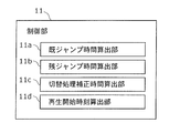
- FIG. 3 is a diagram showing a detailed functional configuration of the control unit 11 shown in FIG.
- the control unit 11 includes a jump time calculation unit 11a, a remaining jump time calculation unit 11b, a switching process correction time calculation unit 11c, and a reproduction start time calculation unit 11d in order to perform fast forward and fast reverse playback control according to the present invention.
- a jump time calculation unit 11a a jump time calculation unit 11a, a remaining jump time calculation unit 11b, a switching process correction time calculation unit 11c, and a reproduction start time calculation unit 11d in order to perform fast forward and fast reverse playback control according to the present invention.
- the target double speed is 10 times, and one I picture is displayed in 10 frames.
- the remaining jump time calculation unit 11b is a processing unit that calculates the remaining jump time in fast forward and fast reverse playback.
- the “remaining jump time” is a jump time when jumping from CELL # n ⁇ 1 (or CELL # n + 1) to CELL # n across video units in fast forward playback (or fast reverse playback). Of these, it is the time to be allocated to the subsequent moving image unit, that is, CELL # n (that is, the remaining time obtained by subtracting the existing jump time from the jump time).
- the switching processing correction time calculation unit 11c is a processing unit that calculates the switching processing correction time in fast forward and fast reverse playback.
- the “switching process correction time” means CELL # n ⁇ 1 (or when switching from CELL # n ⁇ 1 (or CELL # n + 1) to CELL # n in fast forward playback (or fast reverse playback).
- the difference between the actual time when the last image to be displayed in CELL # n + 1) is reproduced and the actual time when the image to be displayed first in CELL # n is reproduced is multiplied by a multiple corresponding to the designated double speed. It was time.
- the reproduction start time calculation unit 11d is calculated by the already jump time calculated by the already jump time calculation unit 11a, the remaining jump time calculated by the remaining jump time calculation unit 11b, and the switching process correction time calculation unit 11c. Based on at least one of the processing correction times, the CELL playback start time after switching when the CELL is switched in fast forward and fast reverse playback is calculated.
- the control unit 11 controls the reproduction unit 14 so that the CELL after switching is reproduced from the reproduction start time calculated by the reproduction start time calculation unit 11d.
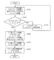
- FIG. 4 is a flowchart showing a playback start time determination method according to the first switching method of the present invention when switching from CELL # n-1 to CELL # n in fast forward playback at the boundary of CELL which is a moving image unit. .
- step S101 the jump time calculation unit 11a substitutes the jump destination position obtained by adding the jump time to the PTS of the frame displayed last in the reproduction process of CELL # n-1 for the variable L1.
- step S103 the reproducing unit 14 reproduces a frame corresponding to the variable L1 of CELL # n-1, and executes again from step S101.
- step S104 the already-jump-time calculating unit 11a substitutes the already-jump time obtained by subtracting the PTS of the frame displayed at the end of CELL # n-1 from the C_V_E_PTM of CELL # n-1 into the variable J1. To do.
- step S105 the remaining jump time calculation unit 11b substitutes the remaining jump time obtained by subtracting the variable J1 calculated in step S104 from the jump time for the variable J2.
- step S106 the reproduction start time calculation unit 11d determines the reproduction start time by adding the variable J2 calculated in step S105 to C_V_S_PTM representing the start time of CELL # n shown in FIG. To do.
- the jump time can be kept constant in the DVD-VR fast-forward playback, so a reduction in the difference between the target double speed and the actual double speed can be expected. .
- FIG. 5 is a flowchart showing a playback start time determination method according to the first switching method of the present invention when switching from CELL # n + 1 to CELL # n in fast reverse playback.
- step S401 the jump time calculation unit 11a substitutes the jump destination position obtained by subtracting the jump time from the PTS of the last frame displayed in the CELL # n + 1 playback process into the variable L1.
- step S402 the already jump time calculation unit 11a checks whether or not the variable L1 calculated in step S401 is smaller than CELL # n + 1 C_V_E_PTM. If it is smaller or equal (YES in S402), it is determined that CELL # n + 1 has been reproduced, and the process proceeds to step S404. If larger (NO in S402), it is determined that CELL # n + 1 is being reproduced, and step S403 is performed. Proceed to
- step S403 the reproducing unit 14 reproduces a frame corresponding to the variable L1 of CELL # n + 1, and executes again from step S401.
- step S404 the already-jump time calculating unit 11a substitutes the already-jump time obtained by subtracting C_V_S_PTM of CELL # n + 1 from the PTS of the frame displayed at the end of CELL # n + 1 into the variable J1.
- step S405 the remaining jump time calculation unit 11b substitutes the remaining jump time obtained by subtracting the variable J1 calculated in step S404 from the jump time for the variable J2.
- step S406 the reproduction start time calculation unit 11d determines the reproduction start time by subtracting the variable J2 calculated in step S405 from C_V_E_PTM of CELL # n.
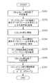
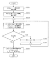
- FIG. 6 is a flowchart showing a playback start time determination method according to the second switching method of the present invention when switching from CELL # n-1 to CELL # n and from CELL # n to CELL # n + 1 in fast-forward playback. .
- step S201 the switching process correction time calculation unit 11c determines whether or not the reproduction of CELL # n-1 has been completed by the same method as in steps S101, S102, and S103 in the first switching method.
- step S202 the switching process correction time calculation unit 11c acquires the actual time when the frame to be displayed at the end of CELL # n-1 is displayed, and substitutes it in the variable T1.
- step S203 the playback unit 14 starts playback of CELL # n.
- step S204 the switching process correction time calculation unit 11c acquires the actual time when the first frame to be displayed in CELL # n is displayed, and substitutes it in the variable T2.
- step S205 the switching process correction time calculation unit 11c is obtained by multiplying the variable T2 obtained in step S204 by the variable T1 obtained in step S202 and the double speed corresponding to the designated double speed.
- the switching process correction time is substituted into a variable T3.
- step S207 the reproduction start time calculation unit 11d determines the reproduction start time by adding the variable T3 calculated in step S205 to C_V_S_PTM of CELL # n + 1.
- FIG. 7 is a flowchart showing a playback start time determination method according to the second switching method of the present invention when switching from CELL # n + 1 to CELL # n and from CELL # n to CELL # n-1 in fast reverse playback. is there.
- step S501 the switching process correction time calculation unit 11c determines whether or not CELL # n + 1 has been reproduced by the same method as in steps S401, S402, and S403 in the first switching method.
- step S502 the switching process correction time calculation unit 11c acquires the actual time when the frame to be displayed at the end of CELL # n + 1 is displayed, and substitutes it in the variable T1.
- step S503 the playback unit 14 starts playback of CELL # n.
- step S504 the switching process correction time calculation unit 11c acquires the actual time when the first frame to be displayed in CELL # n is displayed, and substitutes it in the variable T2.
- step S505 the switching processing correction time calculation unit 11c is obtained by multiplying the variable T2 acquired in step S504 by the variable T1 acquired in step S502 and the double speed corresponding to the specified double speed.
- the switching process correction time is substituted into a variable T3.
- step S506 the reproduction start time calculation unit 11d determines whether or not CELL # n has been reproduced by the same method as in steps S401, S402, and S403 in the first switching method.
- step S507 the reproduction start time calculation unit 11d determines the reproduction start time by subtracting the variable T3 calculated in step S505 from C_V_E_PTM of CELL # n-1.
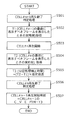
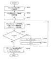
- FIG. 8 is a flowchart showing a playback start time determination method according to the third switching method of the present invention when switching from CELL # n-1 to CELL # n + i in fast forward playback.
- step S301 the reproduction start time calculation unit 11d determines whether or not the reproduction of CELL # n-1 has been completed by the same method as in steps S101, S102, and S103 in the first switching method.
- step S302 the reproduction start time calculation unit 11d adds the variable J2 calculated in step S105 of the first switching method and the variable T3 calculated in step S205 of the second switching method.
- the jump time is substituted into the variable K1.
- the value assigned to the variable K1 may be the variable J2 (remaining jump time) or the variable T3 (switching process correction time).
- step S303 the reproduction start time calculation unit 11d initializes the variable i by substituting 0 therein.
- step S304 the reproduction start time calculation unit 11d substitutes CELL # n + i reproduction time obtained by subtracting C_V_S_PTM of CELL # n + i from C_V_E_PTM of CELL # n + i into a variable P1.
- step S305 the reproduction start time calculation unit 11d checks whether the variable K1 is larger than the variable P1. If the variable K1 is larger or equal (YES in S305), the process proceeds to step S306, and if smaller (S305). NO), the process proceeds to step S308.
- step S306 the reproduction start time calculation unit 11d updates the variable K1 by subtracting the variable P1 from the variable K1.
- step S307 the reproduction start time calculation unit 11d increments the variable i and executes again from step S304.
- step S308 the reproduction start time calculation unit 11d determines the reproduction start time by adding the variable K1 to C_V_S_PTM of CELL # n + i.
- FIG. 9 is a flowchart showing a playback start time determination method according to the third switching method of the present invention when switching from CELL # n + 1 to CELL # n-i in fast reverse playback.
- step S601 the reproduction start time calculation unit 11d determines whether or not CELL # n + 1 has been reproduced by the same method as in steps S401, S402, and S403 in the first switching method.
- step S602 the reproduction start time calculation unit 11d adds the variable J2 calculated in step S405 of the first switching method and the variable T3 calculated in step S505 of the second switching method.
- the jump time is substituted into the variable K1.
- the value assigned to the variable K1 may be the variable J2 (remaining jump time) or the variable T3 (switching process correction time).
- step S603 the reproduction start time calculation unit 11d initializes the variable i by substituting 0 therein.
- step S604 the playback start time calculation unit 11d substitutes CELL # n ⁇ i playback time obtained by subtracting C_V_S_PTM of CELL # n ⁇ i from C_V_E_PTM of CELL # n ⁇ i into variable P1.
- step S605 the reproduction start time calculating unit 11d checks whether or not the variable K1 is larger than the variable P1. If it is larger or equal (YES in S605), the process proceeds to step S606, and if smaller (S605). NO), the process proceeds to step S608.
- step S606 the reproduction start time calculation unit 11d updates the variable K1 by subtracting the variable P1 from the variable K1.
- step S607 the reproduction start time calculation unit 11d increments the variable i and executes again from step S604.
- step S608 the reproduction start time calculation unit 11d determines the reproduction start time by subtracting the variable K1 from C_V_E_PTM of CELL # n-i.
- the jump processing (steps S306 and S307) in the fast-forward playback and the jump processing (steps S606 and S607) in the fast-rewind playback make the sum of the remaining jump time and the switching processing correction time the next moving image unit or a plurality of continuous videos.
- the playback time is longer than the entire video unit, (1) in the case of fast-forward playback, the remaining jump time and the switching process correction time are not used as the playback start time without playing the next video unit or a plurality of continuous video units. Is calculated by adding the time obtained by subtracting the playback time of the next video unit or the whole of multiple continuous video units to the start time of the next video unit of the next video unit or multiple continuous video units.
- the value to be substituted for variable K1 may be variable J2 (remaining jump time) or variable T3 (switching process correction time).
- variable J2 replacement jump time
- T3 switching process correction time
- the next video unit or a plurality of continuous video units are played back. Do not set the playback start time by subtracting the playback time of the next video unit or the whole of multiple continuous video units from the remaining jump time, and the next video unit of the next video unit or the continuous video units. The time added to the start time is calculated.
- the next video unit is calculated from the remaining jump time as the playback start time without playing the next video unit or a plurality of continuous video units.
- variable T3 switching process correction time
- step S306 and S307 the jump process in the fast forward reproduction
- step S606 and S607 the jump process in the fast reverse reproduction. I can say that.
- the playback start time is the next video unit or the next video unit of multiple continuous video units, which is calculated by subtracting the playback time of the next video unit or all of the continuous video units from the switching processing correction time. The time added to the head time of the unit is calculated.
- the reproduction start time is used as the reproduction start time.
- the time taken to switch the moving image unit is absorbed by correcting the playback time, and the effect of reducing the difference between the designated double speed and the actual playback speed can be obtained.
- the present invention is not limited to such embodiments.
- the video playback device has been described.
- the video playback method according to the present invention is not limited to a playback device having only a function of playing back a video, and has a function of recording a video and a function of playing back.
- the present invention can also be applied to a recording / playback apparatus.
- the present invention it is possible to realize fast-forward or fast-rewind playback at a more accurate double speed in a playback unit in which a plurality of video units are connected, and the target scene while checking the content of the video
- the present invention is useful when applied to DVD recorders and players that require a high level of convenience such as quick, accurate, and easy access, and video playback devices built into digital video cameras.
Landscapes
- Engineering & Computer Science (AREA)
- Signal Processing (AREA)
- Multimedia (AREA)
- Television Signal Processing For Recording (AREA)
- Indexing, Searching, Synchronizing, And The Amount Of Synchronization Travel Of Record Carriers (AREA)
- Signal Processing For Digital Recording And Reproducing (AREA)
Priority Applications (2)
| Application Number | Priority Date | Filing Date | Title |
|---|---|---|---|
| CN2011800035594A CN102484691A (zh) | 2010-06-07 | 2011-03-29 | 视频再现方法以及视频再现装置 |
| US13/412,785 US8498521B2 (en) | 2010-06-07 | 2012-03-06 | Video reproduction method and video reproduction device |
Applications Claiming Priority (2)
| Application Number | Priority Date | Filing Date | Title |
|---|---|---|---|
| JP2010-130531 | 2010-06-07 | ||
| JP2010130531A JP2011259110A (ja) | 2010-06-07 | 2010-06-07 | 動画再生方法および動画再生装置 |
Related Child Applications (1)
| Application Number | Title | Priority Date | Filing Date |
|---|---|---|---|
| US13/412,785 Continuation US8498521B2 (en) | 2010-06-07 | 2012-03-06 | Video reproduction method and video reproduction device |
Publications (1)
| Publication Number | Publication Date |
|---|---|
| WO2011155108A1 true WO2011155108A1 (ja) | 2011-12-15 |
Family
ID=45097730
Family Applications (1)
| Application Number | Title | Priority Date | Filing Date |
|---|---|---|---|
| PCT/JP2011/001862 Ceased WO2011155108A1 (ja) | 2010-06-07 | 2011-03-29 | 動画再生方法および動画再生装置 |
Country Status (4)
| Country | Link |
|---|---|
| US (1) | US8498521B2 (enExample) |
| JP (1) | JP2011259110A (enExample) |
| CN (1) | CN102484691A (enExample) |
| WO (1) | WO2011155108A1 (enExample) |
Families Citing this family (2)
| Publication number | Priority date | Publication date | Assignee | Title |
|---|---|---|---|---|
| CN103617240B (zh) * | 2013-11-26 | 2018-01-16 | 广东欧珀移动通信有限公司 | 一种多音频文件的处理方法 |
| JP6452519B2 (ja) * | 2015-03-30 | 2019-01-16 | キヤノン株式会社 | 再生制御装置及びその制御方法、プログラム、並びに記憶媒体 |
Citations (5)
| Publication number | Priority date | Publication date | Assignee | Title |
|---|---|---|---|---|
| JPH09251763A (ja) * | 1996-03-18 | 1997-09-22 | Pioneer Electron Corp | 情報記録媒体並びにその記録装置及び再生装置 |
| JP2002232844A (ja) * | 2001-02-02 | 2002-08-16 | Matsushita Electric Ind Co Ltd | 情報記録媒体、録画装置及び方法、再生装置及び方法並びにプログラム記憶媒体 |
| JP2004213728A (ja) * | 2002-12-27 | 2004-07-29 | Funai Electric Co Ltd | Dvd再生装置及び方法 |
| JP2005521189A (ja) * | 2002-03-20 | 2005-07-14 | コーニンクレッカ フィリップス エレクトロニクス エヌ ヴィ | リアルタイム情報を記録する方法及び装置 |
| JP2007305189A (ja) * | 2006-05-09 | 2007-11-22 | Nec Electronics Corp | 再生装置及び再生方法 |
Family Cites Families (21)
| Publication number | Priority date | Publication date | Assignee | Title |
|---|---|---|---|---|
| JP2737216B2 (ja) * | 1989-03-15 | 1998-04-08 | ソニー株式会社 | ビデオディスクプレーヤ |
| JP3561930B2 (ja) * | 1993-08-14 | 2004-09-08 | ソニー株式会社 | 画像検索用id信号の記録方法、画像検索方法、及び記録画像再生装置 |
| JPH09251761A (ja) * | 1996-03-15 | 1997-09-22 | Pioneer Electron Corp | 情報記録媒体並びにその記録装置及び再生装置 |
| MY116283A (en) | 1997-09-17 | 2003-12-31 | Panasonic Ip Corp America | Optical disc having an area storing original and user chain information specifying at least part of a video object stored on the disc, and a computer program and recording apparatus for recording and editing the chain information. |
| JP3050311B2 (ja) | 1997-09-17 | 2000-06-12 | 松下電器産業株式会社 | 光ディスク、記録装置及び再生装置 |
| US6487364B2 (en) | 1997-09-17 | 2002-11-26 | Matsushita Electric Industrial Co., Ltd. | Optical disc, video data editing apparatus, computer-readable recording medium storing an editing program, reproduction apparatus for the optical disc, and computer-readable recording medium storing a reproduction program |
| CN1311958A (zh) * | 1998-06-11 | 2001-09-05 | 皇家菲利浦电子有限公司 | 数字视频记录器用的特技播放信号的产生 |
| EP0986248A1 (en) * | 1998-09-07 | 2000-03-15 | Deutsche Thomson-Brandt Gmbh | Method and apparatus for timestamping a bitstream to be recorded |
| TW463165B (en) * | 1998-09-07 | 2001-11-11 | Thomson Brandt Gmbh | Method for addressing a bitstream to be recorded or being recorded on a storage medium |
| JP3997640B2 (ja) * | 1999-02-01 | 2007-10-24 | 松下電器産業株式会社 | 情報記録再生装置 |
| US6856755B1 (en) * | 1999-11-10 | 2005-02-15 | Thomson Licensing S.A. | Method and apparatus for editing in a forward or reverse direction on a rewriteable disc media |
| JP4452363B2 (ja) * | 2000-02-23 | 2010-04-21 | 富士通株式会社 | ファイルシステム |
| US7944953B2 (en) * | 2002-04-03 | 2011-05-17 | Tvworks, Llc | Method and apparatus for transmitting data in a data stream |
| US7200321B2 (en) * | 2002-04-19 | 2007-04-03 | Tivo Inc. | Method and apparatus for creating an expanded functionality digital video disc |
| JP4612840B2 (ja) * | 2004-01-23 | 2011-01-12 | キヤノン株式会社 | 情報処理装置及び情報処理方法 |
| ES2383654T3 (es) * | 2004-04-28 | 2012-06-25 | Panasonic Corporation | Aparato de generación de flujos de imágenes en movimiento, aparato de codificaicón de imágenes en movimiento, aparato multiplexador de imágenes en movimiento y aparato de descodificación de imágenes en movimiento |
| WO2006082150A2 (en) * | 2005-02-07 | 2006-08-10 | Thomson Licensing | METHOD AND APPARATUS FOR REPLAYING A VIDEO SIGNAL AND ONE OR MORE AUDIO SIGNALS RELATED TO AUDIO/VIDEO DATA THAT ARE BASED ON A 24Hz FRAME FREQUENCY VIDEO SIGNAL |
| CA2611070C (en) * | 2005-06-03 | 2015-10-06 | Nielsen Media Research, Inc. | Methods and apparatus to detect a time-shift event associated with the presentation of media content |
| JP2007172765A (ja) * | 2005-12-22 | 2007-07-05 | Toshiba Corp | 情報再生装置及び情報再生装置の状況表示方法 |
| JP4642655B2 (ja) * | 2005-12-28 | 2011-03-02 | ソニー株式会社 | 再生装置および再生方法、プログラム、記録媒体、データ構造、記録媒体の製造方法および記録装置、並びに、データ構造の生成方法および生成装置 |
| US8229286B2 (en) * | 2007-03-23 | 2012-07-24 | Nokia Corporation | Method and system for file fast-forwarding and rewind |
-
2010
- 2010-06-07 JP JP2010130531A patent/JP2011259110A/ja active Pending
-
2011
- 2011-03-29 CN CN2011800035594A patent/CN102484691A/zh active Pending
- 2011-03-29 WO PCT/JP2011/001862 patent/WO2011155108A1/ja not_active Ceased
-
2012
- 2012-03-06 US US13/412,785 patent/US8498521B2/en not_active Expired - Fee Related
Patent Citations (5)
| Publication number | Priority date | Publication date | Assignee | Title |
|---|---|---|---|---|
| JPH09251763A (ja) * | 1996-03-18 | 1997-09-22 | Pioneer Electron Corp | 情報記録媒体並びにその記録装置及び再生装置 |
| JP2002232844A (ja) * | 2001-02-02 | 2002-08-16 | Matsushita Electric Ind Co Ltd | 情報記録媒体、録画装置及び方法、再生装置及び方法並びにプログラム記憶媒体 |
| JP2005521189A (ja) * | 2002-03-20 | 2005-07-14 | コーニンクレッカ フィリップス エレクトロニクス エヌ ヴィ | リアルタイム情報を記録する方法及び装置 |
| JP2004213728A (ja) * | 2002-12-27 | 2004-07-29 | Funai Electric Co Ltd | Dvd再生装置及び方法 |
| JP2007305189A (ja) * | 2006-05-09 | 2007-11-22 | Nec Electronics Corp | 再生装置及び再生方法 |
Also Published As
| Publication number | Publication date |
|---|---|
| CN102484691A (zh) | 2012-05-30 |
| US8498521B2 (en) | 2013-07-30 |
| JP2011259110A (ja) | 2011-12-22 |
| US20120163778A1 (en) | 2012-06-28 |
Similar Documents
| Publication | Publication Date | Title |
|---|---|---|
| JP4223800B2 (ja) | 記録装置および記録方法 | |
| US20020126994A1 (en) | Recording apparatus and method with automatic chapter making capability | |
| JP2002216460A (ja) | 情報記録媒体 | |
| US20060182436A1 (en) | Image recording apparatus, image playback control apparatus, image recording and playback control apparatus, processing method therefor, and program for enabling computer to execute same method | |
| US6937540B1 (en) | Information recording device which handles a plurality of recording surfaces and information recording method which handles a plurality of recording surfaces | |
| US6466732B1 (en) | Information recording system and information recording method | |
| JP3772023B2 (ja) | 画像表示装置、同装置に適用される画像切り替え表示方法 | |
| JPWO2009139302A1 (ja) | 録画再生装置 | |
| WO2011155108A1 (ja) | 動画再生方法および動画再生装置 | |
| US20080151060A1 (en) | Camera apparatus and chapter data generating method in camera apparatus | |
| US20030210899A1 (en) | Replace processing method and replace processing apparatus | |
| US20020054753A1 (en) | Recording device which handles recording reservations and recording method which handles recoding reservations | |
| JP2003022604A (ja) | デジタル記録再生装置 | |
| JP3840790B2 (ja) | 情報再生制御装置および情報再生方法 | |
| JP4049177B2 (ja) | 記録装置および記録方法 | |
| JP5487771B2 (ja) | 記録再生装置、記録再生制御方法及び編集システム | |
| JP4036191B2 (ja) | 再生装置及び再生方法 | |
| JP2008234798A (ja) | キューポイント設定装置及び方法、並びに情報再生装置及び情報記録装置 | |
| JP2007049504A (ja) | 記録媒体、再生装置および再生方法 | |
| JP2004253052A (ja) | 情報記録媒体、情報記録装置 | |
| KR20040102962A (ko) | Pvr에서의 하이라이트 스트림 생성 장치 및 그 방법 | |
| JP2009200567A (ja) | 映像記録再生装置 | |
| JP2009033712A (ja) | 再生装置、再生方法、プログラム | |
| JP2008210438A (ja) | 情報記録再生装置 | |
| JP2008152871A (ja) | 情報記録再生装置及び再生装置 |
Legal Events
| Date | Code | Title | Description |
|---|---|---|---|
| WWE | Wipo information: entry into national phase |
Ref document number: 201180003559.4 Country of ref document: CN |
|
| 121 | Ep: the epo has been informed by wipo that ep was designated in this application |
Ref document number: 11792071 Country of ref document: EP Kind code of ref document: A1 |
|
| NENP | Non-entry into the national phase |
Ref country code: DE |
|
| 122 | Ep: pct application non-entry in european phase |
Ref document number: 11792071 Country of ref document: EP Kind code of ref document: A1 |