WO2011148978A1 - Rotor de moteur à induction et moteur à induction utilisant ce rotor - Google Patents
Rotor de moteur à induction et moteur à induction utilisant ce rotor Download PDFInfo
- Publication number
- WO2011148978A1 WO2011148978A1 PCT/JP2011/061989 JP2011061989W WO2011148978A1 WO 2011148978 A1 WO2011148978 A1 WO 2011148978A1 JP 2011061989 W JP2011061989 W JP 2011061989W WO 2011148978 A1 WO2011148978 A1 WO 2011148978A1
- Authority
- WO
- WIPO (PCT)
- Prior art keywords
- conductor
- rotor
- induction motor
- carbon nanotube
- stator
- Prior art date
Links
- 230000006698 induction Effects 0.000 title claims abstract description 44
- 239000004020 conductor Substances 0.000 claims abstract description 113
- OKTJSMMVPCPJKN-UHFFFAOYSA-N Carbon Chemical group [C] OKTJSMMVPCPJKN-UHFFFAOYSA-N 0.000 claims abstract description 54
- 239000002131 composite material Substances 0.000 claims abstract description 30
- 239000002041 carbon nanotube Substances 0.000 claims description 53
- RYGMFSIKBFXOCR-UHFFFAOYSA-N Copper Chemical group [Cu] RYGMFSIKBFXOCR-UHFFFAOYSA-N 0.000 claims description 41
- XAGFODPZIPBFFR-UHFFFAOYSA-N aluminium Chemical compound [Al] XAGFODPZIPBFFR-UHFFFAOYSA-N 0.000 claims description 40
- 229910052782 aluminium Inorganic materials 0.000 claims description 39
- 229910021393 carbon nanotube Inorganic materials 0.000 claims description 35
- 229910052802 copper Inorganic materials 0.000 claims description 25
- 239000010949 copper Substances 0.000 claims description 25
- 238000000034 method Methods 0.000 claims description 10
- 239000002923 metal particle Substances 0.000 claims description 5
- 238000004804 winding Methods 0.000 claims description 4
- 230000008569 process Effects 0.000 claims description 3
- 239000011162 core material Substances 0.000 description 59
- 239000002232 CNT15 Substances 0.000 description 15
- 229910052751 metal Inorganic materials 0.000 description 10
- 239000002184 metal Substances 0.000 description 10
- 239000000835 fiber Substances 0.000 description 9
- 239000002082 metal nanoparticle Substances 0.000 description 8
- 230000004048 modification Effects 0.000 description 8
- 238000012986 modification Methods 0.000 description 8
- 230000002500 effect on skin Effects 0.000 description 5
- 239000000463 material Substances 0.000 description 5
- 230000020169 heat generation Effects 0.000 description 4
- 238000005470 impregnation Methods 0.000 description 4
- AZDRQVAHHNSJOQ-UHFFFAOYSA-N alumane Chemical group [AlH3] AZDRQVAHHNSJOQ-UHFFFAOYSA-N 0.000 description 3
- 238000004519 manufacturing process Methods 0.000 description 3
- 238000009987 spinning Methods 0.000 description 3
- XEEYBQQBJWHFJM-UHFFFAOYSA-N Iron Chemical group [Fe] XEEYBQQBJWHFJM-UHFFFAOYSA-N 0.000 description 2
- 239000000956 alloy Substances 0.000 description 2
- 229910045601 alloy Inorganic materials 0.000 description 2
- 229910052799 carbon Inorganic materials 0.000 description 2
- 238000005260 corrosion Methods 0.000 description 2
- 230000007797 corrosion Effects 0.000 description 2
- 230000000694 effects Effects 0.000 description 2
- 230000005674 electromagnetic induction Effects 0.000 description 2
- 238000005516 engineering process Methods 0.000 description 2
- 230000006872 improvement Effects 0.000 description 2
- 150000002739 metals Chemical class 0.000 description 2
- 230000002093 peripheral effect Effects 0.000 description 2
- 230000009467 reduction Effects 0.000 description 2
- 230000004044 response Effects 0.000 description 2
- 229910052776 Thorium Inorganic materials 0.000 description 1
- 230000009471 action Effects 0.000 description 1
- 230000008901 benefit Effects 0.000 description 1
- 239000011230 binding agent Substances 0.000 description 1
- 239000003575 carbonaceous material Substances 0.000 description 1
- 229910052804 chromium Inorganic materials 0.000 description 1
- 239000012141 concentrate Substances 0.000 description 1
- -1 copper or aluminum Chemical class 0.000 description 1
- 230000017525 heat dissipation Effects 0.000 description 1
- 229910052742 iron Inorganic materials 0.000 description 1
- 229910052748 manganese Inorganic materials 0.000 description 1
- 229910052750 molybdenum Inorganic materials 0.000 description 1
- 229910052758 niobium Inorganic materials 0.000 description 1
- 230000005855 radiation Effects 0.000 description 1
- 230000001360 synchronised effect Effects 0.000 description 1
- 229910052715 tantalum Inorganic materials 0.000 description 1
- 230000009466 transformation Effects 0.000 description 1
- 229910052720 vanadium Inorganic materials 0.000 description 1
- 229910052727 yttrium Inorganic materials 0.000 description 1
Images


Classifications
-
- H—ELECTRICITY
- H02—GENERATION; CONVERSION OR DISTRIBUTION OF ELECTRIC POWER
- H02K—DYNAMO-ELECTRIC MACHINES
- H02K3/00—Details of windings
- H02K3/02—Windings characterised by the conductor material
-
- H—ELECTRICITY
- H02—GENERATION; CONVERSION OR DISTRIBUTION OF ELECTRIC POWER
- H02K—DYNAMO-ELECTRIC MACHINES
- H02K17/00—Asynchronous induction motors; Asynchronous induction generators
- H02K17/02—Asynchronous induction motors
- H02K17/16—Asynchronous induction motors having rotors with internally short-circuited windings, e.g. cage rotors
- H02K17/168—Asynchronous induction motors having rotors with internally short-circuited windings, e.g. cage rotors having single-cage rotors
-
- B—PERFORMING OPERATIONS; TRANSPORTING
- B82—NANOTECHNOLOGY
- B82Y—SPECIFIC USES OR APPLICATIONS OF NANOSTRUCTURES; MEASUREMENT OR ANALYSIS OF NANOSTRUCTURES; MANUFACTURE OR TREATMENT OF NANOSTRUCTURES
- B82Y99/00—Subject matter not provided for in other groups of this subclass
-
- Y—GENERAL TAGGING OF NEW TECHNOLOGICAL DEVELOPMENTS; GENERAL TAGGING OF CROSS-SECTIONAL TECHNOLOGIES SPANNING OVER SEVERAL SECTIONS OF THE IPC; TECHNICAL SUBJECTS COVERED BY FORMER USPC CROSS-REFERENCE ART COLLECTIONS [XRACs] AND DIGESTS
- Y10—TECHNICAL SUBJECTS COVERED BY FORMER USPC
- Y10S—TECHNICAL SUBJECTS COVERED BY FORMER USPC CROSS-REFERENCE ART COLLECTIONS [XRACs] AND DIGESTS
- Y10S977/00—Nanotechnology
- Y10S977/902—Specified use of nanostructure
- Y10S977/932—Specified use of nanostructure for electronic or optoelectronic application
Definitions
- the present invention relates to an induction motor, and more particularly to a rotor of an induction motor that rotates by electromagnetic induction in response to a magnetic force generated by a stator and an induction motor using the same.
- the induction motors disclosed in Patent Documents 1 and 2 are a stator that generates a rotating magnetic field inside the hollow, and is rotatably arranged inside the hollow of the stator, and receives the magnetic force of the magnetic field generated by the stator. It is mainly composed of a rotating rotor.
- the stator is composed of a stator core having a hollow portion inside and a stator coil wound around the inner peripheral portion of the stator core, and a magnetic field is generated inside the hollow by passing an electric current through the stator coil. It is formed.
- the rotor is formed by assembling an iron core part and a squirrel-cage conductor part integrally with a rotating shaft.
- the cage-shaped conductor portion is formed by a pair of annular conductors (end rings) and a plurality of rod-shaped conductors (conductor bars) connected between the pair of annular conductors.
- a rotor is rotatably disposed inside the hollow of the stator, and a magnetic field generated by the stator coil is applied to the rotor by energizing the stator coil, and an electric current (eddy current) is applied to the rod-shaped conductor by this magnetic field.
- the electromagnetic force is generated in the rotor by the current generated in the rod-shaped conductor and the magnetic field from the stator.
- the rotor rotates by the electromagnetic force generated in the rotor. In this case, when the induction motor is started, a high-frequency current flows through the rod-shaped conductor by the magnetic field formed by the stator.
- Such induction motors are simpler and more robust in structure than DC motors and synchronous motors using permanent magnets, and do not require complex control, so they are easy to use, relatively inexpensive, and constant speed. There is an advantage that it can cope with variable speed.
- JP-A-6-165451 Japanese Patent Laid-Open No. 10-32966
- the induction motor has a problem in that the efficiency is poor because the shaft output of the rotor is reduced due to heat loss with respect to the input power.
- the present invention relates to an induction motor rotor that can reduce the heat loss of the induction motor and reduce the size by reducing the electrical resistance of the rotor surface in the rotor of the induction motor, and the same.
- An object is to provide an induction motor.
- a first aspect of the present invention is a rotor of an induction motor that is rotatably arranged inside a hollow of a stator of an induction motor and rotates by receiving a magnetic force from a magnetic field formed in the hollow by the stator.
- a pair of annular conductors and a plurality of rod-shaped conductors connected between the pair of annular conductors to form a cage shape with the pair of annular conductors, the annular conductor and the rod-shaped conductor,
- the gist of the invention is that it is a rotor of an induction motor formed of a composite material composed of a conductive core conductor and a carbon nanotube structure that adheres to the outer periphery of the core conductor in an electrical contact state.
- the annular motor and the rod-shaped conductor of the rotor of the induction motor are formed of the composite material in which the carbon nanotube structure is attached to the outer periphery of the core conductor in an electrical contact state.
- the core conductor may be a copper rod or an aluminum rod.
- the diameter of the core conductor is reduced by using copper or aluminum, which is generally used as a rod-shaped conductor in the induction motor, as the core conductor and attaching the carbon nanotube structure to the outer periphery thereof.
- copper or aluminum which is generally used as a rod-shaped conductor in the induction motor, as the core conductor and attaching the carbon nanotube structure to the outer periphery thereof.
- the carbon nanotube structure is formed of an aggregate of a plurality of carbon nanotubes, and a conductor made of nano metal particles is attached to the surface of each carbon nanotube, the inside of each carbon nanotube, and the carbon nanotube.
- the wettability improving treatment may be performed, and the outer periphery of the core conductor may be attached in a braided shape and impregnated or compacted with aluminum.
- the carbon nanotube structure is formed of an aggregate of a plurality of carbon nanotubes, and a conductor made of nano metal particles is attached to the surface of each carbon nanotube, the inside of each carbon nanotube, and the carbon nanotube.
- the wettability improving treatment may be performed, and the aluminum may be impregnated or compacted and adhered to the outer periphery of the core conductor by horizontal winding.
- electrons can easily enter the carbon nanotubes, and the electrons flow at a high speed, so that the conductivity can be improved, and the electrons can easily enter from one carbon nanotube to another carbon nanotube. Since electrons can flow at high speed, the conductivity can be further improved.
- a stator that forms a magnetic field in a hollow interior, and a stator that is rotatably disposed in the hollow interior of the stator and rotates by receiving a magnetic force from the magnetic field formed by the stator.
- a rotor, and the rotor includes a pair of annular conductors and a plurality of rod-shaped conductors connected between the pair of annular conductors, the pair of annular conductors and the plurality of rod-shaped conductors
- the annular conductor and the rod-shaped conductor are each formed of a composite material composed of a conductive core conductor and a carbon nanotube structure that adheres to the outer periphery of the core conductor in an electrical contact state.
- the main point is that the induction motor is used.
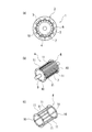
- FIG. 1 shows an induction motor
- FIG. 1 (a) is a sectional view thereof
- FIG. 1 (b) is a perspective view showing a rotor
- FIG. 1 (c) is a perspective view showing a cage of the rotor.
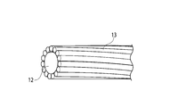
- FIG. 2 is a perspective view showing a composite material in which spun carbon nanotubes are attached in a braided shape to the surface of a copper bar.
- FIG. 3 shows a composite material in which spun carbon nanotubes are attached to the surface of a copper bar and impregnated with aluminum
- FIG. 3 (a) is a perspective view thereof
- FIG. 3 (b) is a sectional view thereof.
- FIG. 1 shows an induction motor
- FIG. 1 (a) is a sectional view thereof
- FIG. 1 (b) is a perspective view showing a rotor
- FIG. 1 (c) is a perspective view showing a cage of the rotor.
- FIG. 2 is a perspective view showing a composite material in which spun
- FIG. 4 is an explanatory view showing a state in which a conductor (nano metal particle) is attached to the carbon nanotube.
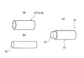
- FIG. 5 is a perspective view illustrating a composite material in which the spun carbon nanotubes are attached in a horizontal winding shape on the surface of a copper bar material according to a first modification.
- FIG. 6 shows a second modification, showing a composite material in which a spun carbon nanotube impregnated with aluminum is adhered to the surface of a copper bar
- FIG. 6 (a) is a composite in which aluminum is impregnated with carbon nanotubes.
- FIG. 6B is a perspective view showing a copper bar
- FIG. 6C is a perspective view showing a state in which the copper bar is press-fitted into the hollow inside of the composite material.
- FIG. 7 is a cross-sectional view showing a comparison between the diameters of a copper bar and a composite material in which carbon nanotubes are attached to the surface of a copper bar.
- an induction motor 1 includes a stator 2 that generates a rotating magnetic field, and a rotor 2 that is rotatably disposed within a hollow interior 3 of the stator 2, and electromagnetic waves generated by the rotating magnetic field generated by the stator 2. It is formed with a rotor 4 that rotates in response to force.
- the stator 2 is composed of a stator core 6 having a hollow portion 5 inside a columnar shape, and a stator coil (not shown) wound around an inner peripheral portion of the stator core 6.
- a magnetic field is formed in the hollow interior 3 by passing an electric current.
- a high-frequency induced current flows through the rotor 4 by the magnetic force from the magnetic field, and a rotational force is generated by the induced current and the magnetic field generated by the stator 2, and the rotor 4 rotates in the hollow interior 3.
- the rotor 4 is formed by integrally assembling a core portion 7 and a cage-shaped conductor portion 8 to a rotation shaft (output shaft) 9 as shown in FIG.
- the cage-shaped conductor portion 8 includes a pair of annular conductors (hereinafter referred to as “end rings”) 10 and 10, and a plurality of conductors connected between the pair of end rings 10 and 10.
- the rod-shaped conductor (hereinafter referred to as “conductor bar”) 11 is formed.
- the end rings 10, 10 and the conductor bar 11 of the present embodiment are attached to the conductive core conductor 12 and the outer periphery of the core conductor 12 in an electrical contact state.
- CNT Carbon nanotube
- the core conductor 12 is formed of a copper core material formed of a copper rod body or an aluminum core material formed of an aluminum rod body, and has high conductivity, high current density resistance, and high thermal conductivity in any material. It is made of a material with excellent properties. In the example of this embodiment, it is formed of a copper core material made of a copper rod. A carbon nanotube structure 13 made of CNTs 15 formed in a braided shape is attached to the outer periphery of the copper core material, and in this state, impregnated with aluminum.
- the CNT 15 is a structure in which a hexagonal shape in which six carbons are bonded is formed in a cylindrical shape in a state where it is combined with another hexagon, and a fiber CNT is formed from the plurality of CNTs 15. Then, the entangled fibers CNT are stretched and aligned from an aggregate of a plurality of fibers CNTs, and twisted to form a uniform and constant thread shape, thereby forming a spun CNT.
- the fiber CNT, the aggregate of the fiber CNT, and the spun CNT are referred to as the CNT structure 13.
- the composite material 14 according to the present embodiment has a metal nanoparticle (conductor) in the surface of the CNTs 15, inside the CNTs 15, and between the CNTs 15. Is applied on the nanoscale, so that wettability improving treatment for improving so-called wettability is performed.
- FIG. 1 As a method of this wettability improving treatment, a technique of “an assembly of carbon and non-carbon and an manufacturing method thereof” described in JP-T-2009-535294, which has already been filed, is used in FIG.
- the non-carbon material Fe, Si, Co, Cr, Mn, Mo, Nb, Ta, Th, Ti, U, V, Y, the surface of the CNT 15, the inside of the CNT 15, and the CNT 15 between the CNT 15, Zr
- the CNTs 15 become strong bonds (covalent bonds) by the metal nanoparticles 18, and the resistance between the metal nanoparticles 18 can be reduced, so that the resistance between the CNTs 15 becomes low.
- the metal nanoparticles 18 attached to the surface of the CNT 15 make it easier for electrons to pass through the inside of the CNT 15 through the metal nanoparticles 18, and the electrons more easily flow through the metal nanoparticles 18 attached to the inside of the CNT 15. As a result, high conductivity can be obtained.
- the entangled fiber CNTs are stretched and aligned from the aggregate of the fiber CNTs formed from such CNTs 15 and twisted to form a spun CNT formed into a uniform and constant thread shape on the surface of the copper core (outer periphery) ) In a braided shape.
- the CNT structure 13 is impregnated with aluminum 16 in a state where the braided CNT structure 13 is attached to the outer periphery of the copper core material that is the core conductor 12.
- the spinning CNT is impregnated with the aluminum 16 by a vacuum pressure impregnation method.
- the technology of “composite material and manufacturing method thereof” described in Japanese Patent Application Laid-Open No. 2001-107203, the technology of “composite material” described in Japanese Patent Application Laid-Open No. 2002-59257, Spinning CNT (CNT structure 13) can be impregnated with aluminum 16 by using the technique of “composite material and manufacturing method thereof” described in JP-A-2002-194515.
- a composite material 14 including the core conductor 12 and the CNT structure 13 is formed, and the end ring 10 and the conductor bar 11 of the induction motor 1 are formed by the composite material 14.
- the CNT structure 13 is attached to the outer periphery of the core conductor 12 made of a copper core material in a braided shape to form a braid.
- a CNT structure 13 is attached to the outer periphery of a core conductor 12 made of a core material in a horizontal winding shape.
- the aluminum 16 is impregnated by the vacuum pressure impregnation method as in the above embodiment.
- the CNT structure 13 is attached to the outer periphery of the core conductor 12, and then the aluminum 16 is impregnated.
- the CNT 15 has the same wettability as in the above embodiment.
- a composite material 17 in which aluminum 16 is impregnated with an assembly of CNT 15 fibers by a vacuum pressure impregnation method similar to that of the above-described embodiment in a state of being subjected to the improvement treatment is cylindrical (as shown in FIG. 6A).
- the core conductor 12 made of a copper core material shown in FIG. 6B is formed in the cylindrical composite material 17 formed into a tube shape and the aggregate of CNT fibers impregnated with aluminum 16 in FIG.
- the composite material 14 including the core conductor 12 and the composite material 17 is formed by press-fitting as shown in c).
- the core conductor 12 is press-fitted into the composite material 17 of the cylindrical CNT structure 13 impregnated with aluminum 16, but the inside of the cylindrical composite material 17 is swallowed.
- the inner surface of the composite material 17 of the cylindrical CNT structure 13 impregnated with aluminum 16 may be brought into close contact with the surface of the copper core material by squeezing.
- the composite material 14 including the conductive core conductor 12 and the CNT structure 13 attached to the outer periphery of the core conductor 12 in an electrical contact state By forming the end rings 10, 10 and the conductor bar 11, even if a high-frequency current generated by electromagnetic induction flows on the surface of the end rings 10, 10, and the conductor bar 11, from the CNT 15 having high conductivity on the surface side. Since the CNT structure 13 to be attached is attached, the resistance can be reduced.
- the electrical resistance of the surface can be reduced, the heat loss is reduced because the amount of heat generated is small even if the high frequency current is concentrated on the surface side due to the skin effect.
- the amount of heat generation can be reduced and heat dissipation is good, so it is possible to reduce or eliminate the heat-dissipating fins conventionally required in induction motors, and thus the size of induction motors can be reduced. For example, when it is used for in-vehicle use, the required mounting space can be reduced.
- it is possible to reduce the weight by reducing the size it is possible to contribute to reducing the weight of the vehicle when it is used in a vehicle.
- the CNT structure 13 is lighter than other conductors (aluminum and copper), when the copper core material is used, if the required diameter of the conductor bar 11 or the end ring 10 is the same, it adheres to the outer periphery. Since the diameter of the copper core material can be reduced by the amount of the CNT structure 13 to be performed, the weight of the entire induction motor can be reduced. Further, as shown in FIG. 7, it is formed of the composite material 14 of this embodiment having the same conductivity as that of the end ring 10 and the conductor bar 11 by the copper core material 19 that has been set to the required diameter L1 in the past. In this case, the diameter L2 can be made smaller than L1.
- the electrical contact between the CNT structure 13 and the copper core material can be remarkably improved. It can be reduced and a composite material with good conductivity can be obtained.
- the CNT structure 13 is formed in a cylindrical shape, but may be formed in a cylindrical shape other than the cylindrical shape.
- the core conductor 12 is formed with the copper core material which consists of a copper rod, and the example which impregnated or compacted aluminum as a conductive metal to CNT15 was shown, and a conductive metal core material
- a conductive metal may be arranged around the CNT structure 13 impregnated or compacted with a conductive metal.
- Core conductor 12 CNT structure (a) Copper core material Aluminum attached (in the above embodiment and Modification) (B) Aluminum core material Copper adheres (c) Copper core material Copper adheres (d) Aluminum core material Aluminum adheres
- (2)-(a) and (b) can reduce corrosion because the core conductor (outer conductor) to which copper adheres is on the outer periphery.
Landscapes
- Engineering & Computer Science (AREA)
- Power Engineering (AREA)
- Induction Machinery (AREA)
- Windings For Motors And Generators (AREA)
Abstract
L'invention porte sur un rotor (4) qui est monté rotatif à l'intérieur de la section intérieure creuse (3) du stator (2) d'un moteur à induction (1) et qui tourne sous l'effet de la réception d'une force magnétique résultant du champ magnétique créé à l'intérieur de la section intérieure creuse (3) par le stator (2). Le rotor (4) comprend : une paire de conducteurs annulaires (10, 10) ; et une pluralité de conducteurs (11) en forme de barre qui sont connectés entre la paire de conducteurs annulaires (10, 10) et qui forment une forme de cage en combinaison avec le paire de conducteurs annulaires (10, 10). Les conducteurs annulaires (10, 10) et les conducteurs en forme de barre (11) sont faits d'une matière composite qui est constituée par une conducteur d'âme électroconducteur (12) et une structure de nanotube de carbone (15) qui adhère à la périphérie extérieure du conducteur d'âme (12) dans un état de contact électrique.
Priority Applications (3)
| Application Number | Priority Date | Filing Date | Title |
|---|---|---|---|
| US13/699,889 US20130181570A1 (en) | 2010-05-27 | 2011-05-25 | Rotor of induction motor, and induction motor using same |
| EP11786677.2A EP2579433A4 (fr) | 2010-05-27 | 2011-05-25 | Rotor de moteur à induction et moteur à induction utilisant ce rotor |
| CN201180026254.5A CN102918754B (zh) | 2010-05-27 | 2011-05-25 | 感应电动机的转子、以及使用该转子的感应电动机 |
Applications Claiming Priority (2)
| Application Number | Priority Date | Filing Date | Title |
|---|---|---|---|
| JP2010-121987 | 2010-05-27 | ||
| JP2010121987 | 2010-05-27 |
Publications (1)
| Publication Number | Publication Date |
|---|---|
| WO2011148978A1 true WO2011148978A1 (fr) | 2011-12-01 |
Family
ID=45003967
Family Applications (1)
| Application Number | Title | Priority Date | Filing Date |
|---|---|---|---|
| PCT/JP2011/061989 WO2011148978A1 (fr) | 2010-05-27 | 2011-05-25 | Rotor de moteur à induction et moteur à induction utilisant ce rotor |
Country Status (5)
| Country | Link |
|---|---|
| US (1) | US20130181570A1 (fr) |
| EP (1) | EP2579433A4 (fr) |
| JP (1) | JP5825848B2 (fr) |
| CN (1) | CN102918754B (fr) |
| WO (1) | WO2011148978A1 (fr) |
Cited By (1)
| Publication number | Priority date | Publication date | Assignee | Title |
|---|---|---|---|---|
| WO2013175335A1 (fr) * | 2012-05-22 | 2013-11-28 | Koninklijke Philips N.V. | Rotor de tube à rayons x comprenant un matériau composite à base de carbone |
Families Citing this family (15)
| Publication number | Priority date | Publication date | Assignee | Title |
|---|---|---|---|---|
| EP2637868A4 (fr) * | 2010-11-12 | 2015-04-22 | Nanocomp Technologies Inc | Systèmes et procédés pour la gestion thermique de composants électroniques |
| CN102815667B (zh) * | 2012-07-03 | 2014-05-28 | 清华大学 | 一种碳纳米管线轴及其制备方法与编织方法 |
| JP6232294B2 (ja) * | 2014-01-09 | 2017-11-15 | 東芝産業機器システム株式会社 | 誘導モータ |
| DE102014208399A1 (de) * | 2014-05-06 | 2015-11-12 | Siemens Aktiengesellschaft | Kurzschlussläufer für eine elektrische Maschine |
| EP3288159A1 (fr) | 2016-08-24 | 2018-02-28 | Siemens Aktiengesellschaft | Rotor en court-circuit en particulier pour dispositifs a haut regime |
| KR101956153B1 (ko) | 2018-10-04 | 2019-06-24 | 어썸레이 주식회사 | 탄소나노튜브를 포함하는 얀의 제조방법 및 이로부터 제조된 얀 |
| KR101962215B1 (ko) | 2018-11-30 | 2019-03-26 | 어썸레이 주식회사 | 일 방향으로 정렬된 얀을 포함하는 탄소나노튜브 시트를 제조하는 방법 및 이에 의해 제조된 탄소나노튜브 시트 |
| KR102131542B1 (ko) * | 2018-12-26 | 2020-07-07 | 전주대학교 산학협력단 | 알루미늄, 다중벽 탄소나노튜브, 철 및 코발트가 포함된 혼성복합체를 이용한 브러시리스 dc모터코어 |
| KR101992745B1 (ko) * | 2019-01-24 | 2019-06-26 | 어썸레이 주식회사 | 구조적 안정성이 우수하고 전자 방출 효율이 향상된 이미터 및 이를 포함하는 x-선 튜브 |
| WO2020203726A1 (fr) * | 2019-03-29 | 2020-10-08 | 古河電気工業株式会社 | Moteur sans noyau |
| KR102099410B1 (ko) | 2019-04-04 | 2020-04-09 | 어썸레이 주식회사 | 세라믹계 소재로 이루어진 집속전극을 포함하는 x-선 발생장치 |
| JP2020196145A (ja) * | 2019-05-31 | 2020-12-10 | 日立造船株式会社 | 積層体および積層体の製造方法 |
| KR102099411B1 (ko) | 2019-07-26 | 2020-04-09 | 어썸레이 주식회사 | 구조적 안정성이 우수한 전계 방출 장치 및 이를 포함하는 x-선 튜브 |
| KR102330120B1 (ko) * | 2021-01-28 | 2021-11-23 | 어썸레이 주식회사 | 식물에 전자기파를 조사하는 장치 및 그 방법 |
| JP7616002B2 (ja) | 2021-10-08 | 2025-01-17 | トヨタ自動車株式会社 | ロータコアおよびロータコアの製造方法 |
Citations (9)
| Publication number | Priority date | Publication date | Assignee | Title |
|---|---|---|---|---|
| JPS5130903A (en) * | 1974-09-11 | 1976-03-16 | Hitachi Ltd | Kogatajudodendoki no kaitenshidotai |
| JPH06165451A (ja) | 1992-11-18 | 1994-06-10 | Hitachi Koki Co Ltd | かご形誘導モータ |
| JPH1032966A (ja) | 1996-07-12 | 1998-02-03 | Hitachi Ltd | 誘導電動機の回転子 |
| JPH1098843A (ja) * | 1996-09-20 | 1998-04-14 | Hitachi Ltd | 回転電機 |
| JP2001107203A (ja) | 1999-09-30 | 2001-04-17 | Yazaki Corp | 複合材料及びその製造方法 |
| JP2002059257A (ja) | 2000-08-11 | 2002-02-26 | Yazaki Corp | 複合材料 |
| JP2002194515A (ja) | 2000-12-28 | 2002-07-10 | Yazaki Corp | 複合材料及びその製造方法 |
| JP2004303962A (ja) * | 2003-03-31 | 2004-10-28 | Yokohama Rubber Co Ltd:The | 高周波回路基板及びその製造方法 |
| JP2009535294A (ja) | 2006-05-01 | 2009-10-01 | 矢崎総業株式会社 | 炭素と非炭素との組織化されたアセンブリー、およびその製造方法 |
Family Cites Families (13)
| Publication number | Priority date | Publication date | Assignee | Title |
|---|---|---|---|---|
| US5068560A (en) * | 1990-12-26 | 1991-11-26 | Lynn Lundquist | Reduced current starting mechanism for three phase squirrel cage motors |
| JPH04308446A (ja) * | 1991-04-05 | 1992-10-30 | Furukawa Electric Co Ltd:The | 回転電機の回転子導体 |
| CN2132332Y (zh) * | 1992-03-30 | 1993-05-05 | 王英录 | 异步电动机复合材料高电阻防断裂起动鼠笼 |
| SE0001748D0 (sv) * | 2000-03-30 | 2000-05-12 | Abb Ab | Induktionslindning |
| ITRM20040571A1 (it) * | 2004-11-22 | 2005-02-22 | Gen Services Srl | Rotore, relativo procedimento di fabbricazione, e macchina ad induzione impiegante il rotore. |
| JP2006265667A (ja) * | 2005-03-24 | 2006-10-05 | Totoku Electric Co Ltd | カーボン複合めっき電線及びその製造方法 |
| JP2007157372A (ja) * | 2005-12-01 | 2007-06-21 | Nissan Motor Co Ltd | 軽量高導電率電線及びその製造方法 |
| KR100842985B1 (ko) * | 2006-07-21 | 2008-07-01 | 엘에스전선 주식회사 | 극세동축케이블 |
| JP5010300B2 (ja) * | 2007-02-02 | 2012-08-29 | 富士電線工業株式会社 | 同軸ケーブル、及び同軸ケーブル用内部導体の製造方法 |
| JP4483952B2 (ja) * | 2008-01-29 | 2010-06-16 | 株式会社デンソー | モータ付ポンプ |
| DE102008025702A1 (de) * | 2008-05-29 | 2009-12-10 | Siemens Aktiengesellschaft | Asynchronmaschine mit verbesserten mechanischen Eigenschaften und Verfahren zum Herstellen eines Läufers für eine Asynchronmaschine |
| US8354593B2 (en) * | 2009-07-10 | 2013-01-15 | Nanocomp Technologies, Inc. | Hybrid conductors and method of making same |
| US8448328B2 (en) * | 2010-01-06 | 2013-05-28 | GM Global Technology Operations LLC | Methods of making aluminum based composite squirrel cage for induction rotor |
-
2011
- 2011-05-25 US US13/699,889 patent/US20130181570A1/en not_active Abandoned
- 2011-05-25 JP JP2011116988A patent/JP5825848B2/ja active Active
- 2011-05-25 EP EP11786677.2A patent/EP2579433A4/fr not_active Withdrawn
- 2011-05-25 CN CN201180026254.5A patent/CN102918754B/zh active Active
- 2011-05-25 WO PCT/JP2011/061989 patent/WO2011148978A1/fr active Application Filing
Patent Citations (9)
| Publication number | Priority date | Publication date | Assignee | Title |
|---|---|---|---|---|
| JPS5130903A (en) * | 1974-09-11 | 1976-03-16 | Hitachi Ltd | Kogatajudodendoki no kaitenshidotai |
| JPH06165451A (ja) | 1992-11-18 | 1994-06-10 | Hitachi Koki Co Ltd | かご形誘導モータ |
| JPH1032966A (ja) | 1996-07-12 | 1998-02-03 | Hitachi Ltd | 誘導電動機の回転子 |
| JPH1098843A (ja) * | 1996-09-20 | 1998-04-14 | Hitachi Ltd | 回転電機 |
| JP2001107203A (ja) | 1999-09-30 | 2001-04-17 | Yazaki Corp | 複合材料及びその製造方法 |
| JP2002059257A (ja) | 2000-08-11 | 2002-02-26 | Yazaki Corp | 複合材料 |
| JP2002194515A (ja) | 2000-12-28 | 2002-07-10 | Yazaki Corp | 複合材料及びその製造方法 |
| JP2004303962A (ja) * | 2003-03-31 | 2004-10-28 | Yokohama Rubber Co Ltd:The | 高周波回路基板及びその製造方法 |
| JP2009535294A (ja) | 2006-05-01 | 2009-10-01 | 矢崎総業株式会社 | 炭素と非炭素との組織化されたアセンブリー、およびその製造方法 |
Non-Patent Citations (1)
| Title |
|---|
| See also references of EP2579433A4 |
Cited By (2)
| Publication number | Priority date | Publication date | Assignee | Title |
|---|---|---|---|---|
| WO2013175335A1 (fr) * | 2012-05-22 | 2013-11-28 | Koninklijke Philips N.V. | Rotor de tube à rayons x comprenant un matériau composite à base de carbone |
| US9853511B2 (en) | 2012-05-22 | 2017-12-26 | Koninklijke Philips N.V. | X-ray tube rotor with carbon composite based material |
Also Published As
| Publication number | Publication date |
|---|---|
| CN102918754B (zh) | 2015-03-11 |
| EP2579433A4 (fr) | 2017-01-18 |
| US20130181570A1 (en) | 2013-07-18 |
| JP2012010583A (ja) | 2012-01-12 |
| EP2579433A1 (fr) | 2013-04-10 |
| CN102918754A (zh) | 2013-02-06 |
| JP5825848B2 (ja) | 2015-12-02 |
Similar Documents
| Publication | Publication Date | Title |
|---|---|---|
| JP5825848B2 (ja) | 誘導モータの回転子の製造方法 | |
| JP4489096B2 (ja) | 電気機器用磁性粉金属複合体コア | |
| US20140339831A1 (en) | Dynamoelectric device | |
| US10312776B2 (en) | Synchronous motor with permanent magnets | |
| WO2018225587A1 (fr) | Machine dynamo-électrique | |
| JP5876993B2 (ja) | 導電材及び導電材の製造方法 | |
| KR101955030B1 (ko) | 2개의 회전자를 이용하는 발전기 | |
| US20020186113A1 (en) | Induction winding | |
| JPWO2019163021A1 (ja) | 固定子、電動機、圧縮機および空気調和装置 | |
| CN112271836A (zh) | 定子、电机和压缩机 | |
| CN111937088B (zh) | 线圈用碳纳米管被覆线材、利用线圈用碳纳米管被覆线材的线圈以及碳纳米管被覆线材线圈的制造方法 | |
| AU2015233650B2 (en) | Electric machine | |
| CN110098681B (zh) | 一种盘式电机绕组 | |
| CN107005110B (zh) | 磁铁嵌入型旋转电机 | |
| CN110190692A (zh) | 旋转电机的定子 | |
| KR20240000244U (ko) | 고속 송풍통 브러시리스 모터 | |
| KR101955031B1 (ko) | 2개의 회전자가 수 분할된 자석을 이용하는 발전기 | |
| JP4613833B2 (ja) | 表面磁石型回転電機およびその製造方法 | |
| KR101315386B1 (ko) | 코일 및 이를 구비한 회전기 | |
| JP2017174690A (ja) | カーボンナノチューブ線材の接続方法及びカーボンナノチューブ線材接続構造体 | |
| KR101758103B1 (ko) | 그래핀 전동기 | |
| JP2009268245A (ja) | 回転電機の固定子 | |
| JP7483150B2 (ja) | 電動機 | |
| WO2020024138A1 (fr) | Moteur hybride à basse consommation à force magnétique variable | |
| JP2011199994A (ja) | 回転電機 |
Legal Events
| Date | Code | Title | Description |
|---|---|---|---|
| WWE | Wipo information: entry into national phase |
Ref document number: 201180026254.5 Country of ref document: CN |
|
| 121 | Ep: the epo has been informed by wipo that ep was designated in this application |
Ref document number: 11786677 Country of ref document: EP Kind code of ref document: A1 |
|
| NENP | Non-entry into the national phase |
Ref country code: DE |
|
| WWE | Wipo information: entry into national phase |
Ref document number: 2011786677 Country of ref document: EP |
|
| WWE | Wipo information: entry into national phase |
Ref document number: 13699889 Country of ref document: US |