WO2011148806A1 - 排気ガス浄化装置 - Google Patents
排気ガス浄化装置 Download PDFInfo
- Publication number
- WO2011148806A1 WO2011148806A1 PCT/JP2011/061196 JP2011061196W WO2011148806A1 WO 2011148806 A1 WO2011148806 A1 WO 2011148806A1 JP 2011061196 W JP2011061196 W JP 2011061196W WO 2011148806 A1 WO2011148806 A1 WO 2011148806A1
- Authority
- WO
- WIPO (PCT)
- Prior art keywords
- exhaust pipe
- exhaust gas
- exhaust
- reducing agent
- gas purification
- Prior art date
Links
Images


Classifications
-
- F—MECHANICAL ENGINEERING; LIGHTING; HEATING; WEAPONS; BLASTING
- F01—MACHINES OR ENGINES IN GENERAL; ENGINE PLANTS IN GENERAL; STEAM ENGINES
- F01N—GAS-FLOW SILENCERS OR EXHAUST APPARATUS FOR MACHINES OR ENGINES IN GENERAL; GAS-FLOW SILENCERS OR EXHAUST APPARATUS FOR INTERNAL COMBUSTION ENGINES
- F01N3/00—Exhaust or silencing apparatus having means for purifying, rendering innocuous, or otherwise treating exhaust
- F01N3/08—Exhaust or silencing apparatus having means for purifying, rendering innocuous, or otherwise treating exhaust for rendering innocuous
- F01N3/10—Exhaust or silencing apparatus having means for purifying, rendering innocuous, or otherwise treating exhaust for rendering innocuous by thermal or catalytic conversion of noxious components of exhaust
- F01N3/24—Exhaust or silencing apparatus having means for purifying, rendering innocuous, or otherwise treating exhaust for rendering innocuous by thermal or catalytic conversion of noxious components of exhaust characterised by constructional aspects of converting apparatus
- F01N3/28—Construction of catalytic reactors
- F01N3/2892—Exhaust flow directors or the like, e.g. upstream of catalytic device
-
- B—PERFORMING OPERATIONS; TRANSPORTING
- B01—PHYSICAL OR CHEMICAL PROCESSES OR APPARATUS IN GENERAL
- B01D—SEPARATION
- B01D53/00—Separation of gases or vapours; Recovering vapours of volatile solvents from gases; Chemical or biological purification of waste gases, e.g. engine exhaust gases, smoke, fumes, flue gases, aerosols
- B01D53/34—Chemical or biological purification of waste gases
- B01D53/92—Chemical or biological purification of waste gases of engine exhaust gases
-
- B—PERFORMING OPERATIONS; TRANSPORTING
- B01—PHYSICAL OR CHEMICAL PROCESSES OR APPARATUS IN GENERAL
- B01F—MIXING, e.g. DISSOLVING, EMULSIFYING OR DISPERSING
- B01F25/00—Flow mixers; Mixers for falling materials, e.g. solid particles
- B01F25/10—Mixing by creating a vortex flow, e.g. by tangential introduction of flow components
- B01F25/103—Mixing by creating a vortex flow, e.g. by tangential introduction of flow components with additional mixing means other than vortex mixers, e.g. the vortex chamber being positioned in another mixing chamber
-
- B—PERFORMING OPERATIONS; TRANSPORTING
- B01—PHYSICAL OR CHEMICAL PROCESSES OR APPARATUS IN GENERAL
- B01F—MIXING, e.g. DISSOLVING, EMULSIFYING OR DISPERSING
- B01F25/00—Flow mixers; Mixers for falling materials, e.g. solid particles
- B01F25/30—Injector mixers
- B01F25/31—Injector mixers in conduits or tubes through which the main component flows
- B01F25/313—Injector mixers in conduits or tubes through which the main component flows wherein additional components are introduced in the centre of the conduit
- B01F25/3131—Injector mixers in conduits or tubes through which the main component flows wherein additional components are introduced in the centre of the conduit with additional mixing means other than injector mixers, e.g. screens, baffles or rotating elements
-
- F—MECHANICAL ENGINEERING; LIGHTING; HEATING; WEAPONS; BLASTING
- F01—MACHINES OR ENGINES IN GENERAL; ENGINE PLANTS IN GENERAL; STEAM ENGINES
- F01N—GAS-FLOW SILENCERS OR EXHAUST APPARATUS FOR MACHINES OR ENGINES IN GENERAL; GAS-FLOW SILENCERS OR EXHAUST APPARATUS FOR INTERNAL COMBUSTION ENGINES
- F01N13/00—Exhaust or silencing apparatus characterised by constructional features ; Exhaust or silencing apparatus, or parts thereof, having pertinent characteristics not provided for in, or of interest apart from, groups F01N1/00 - F01N5/00, F01N9/00, F01N11/00
- F01N13/009—Exhaust or silencing apparatus characterised by constructional features ; Exhaust or silencing apparatus, or parts thereof, having pertinent characteristics not provided for in, or of interest apart from, groups F01N1/00 - F01N5/00, F01N9/00, F01N11/00 having two or more separate purifying devices arranged in series
- F01N13/0097—Exhaust or silencing apparatus characterised by constructional features ; Exhaust or silencing apparatus, or parts thereof, having pertinent characteristics not provided for in, or of interest apart from, groups F01N1/00 - F01N5/00, F01N9/00, F01N11/00 having two or more separate purifying devices arranged in series the purifying devices are arranged in a single housing
-
- B—PERFORMING OPERATIONS; TRANSPORTING
- B01—PHYSICAL OR CHEMICAL PROCESSES OR APPARATUS IN GENERAL
- B01F—MIXING, e.g. DISSOLVING, EMULSIFYING OR DISPERSING
- B01F25/00—Flow mixers; Mixers for falling materials, e.g. solid particles
- B01F2025/93—Arrangements, nature or configuration of flow guiding elements
- B01F2025/931—Flow guiding elements surrounding feed openings, e.g. jet nozzles
-
- F—MECHANICAL ENGINEERING; LIGHTING; HEATING; WEAPONS; BLASTING
- F01—MACHINES OR ENGINES IN GENERAL; ENGINE PLANTS IN GENERAL; STEAM ENGINES
- F01N—GAS-FLOW SILENCERS OR EXHAUST APPARATUS FOR MACHINES OR ENGINES IN GENERAL; GAS-FLOW SILENCERS OR EXHAUST APPARATUS FOR INTERNAL COMBUSTION ENGINES
- F01N2240/00—Combination or association of two or more different exhaust treating devices, or of at least one such device with an auxiliary device, not covered by indexing codes F01N2230/00 or F01N2250/00, one of the devices being
- F01N2240/20—Combination or association of two or more different exhaust treating devices, or of at least one such device with an auxiliary device, not covered by indexing codes F01N2230/00 or F01N2250/00, one of the devices being a flow director or deflector
-
- F—MECHANICAL ENGINEERING; LIGHTING; HEATING; WEAPONS; BLASTING
- F01—MACHINES OR ENGINES IN GENERAL; ENGINE PLANTS IN GENERAL; STEAM ENGINES
- F01N—GAS-FLOW SILENCERS OR EXHAUST APPARATUS FOR MACHINES OR ENGINES IN GENERAL; GAS-FLOW SILENCERS OR EXHAUST APPARATUS FOR INTERNAL COMBUSTION ENGINES
- F01N2470/00—Structure or shape of gas passages, pipes or tubes
- F01N2470/18—Structure or shape of gas passages, pipes or tubes the axis of inlet or outlet tubes being other than the longitudinal axis of apparatus
-
- F—MECHANICAL ENGINEERING; LIGHTING; HEATING; WEAPONS; BLASTING
- F01—MACHINES OR ENGINES IN GENERAL; ENGINE PLANTS IN GENERAL; STEAM ENGINES
- F01N—GAS-FLOW SILENCERS OR EXHAUST APPARATUS FOR MACHINES OR ENGINES IN GENERAL; GAS-FLOW SILENCERS OR EXHAUST APPARATUS FOR INTERNAL COMBUSTION ENGINES
- F01N2610/00—Adding substances to exhaust gases
- F01N2610/02—Adding substances to exhaust gases the substance being ammonia or urea
-
- F—MECHANICAL ENGINEERING; LIGHTING; HEATING; WEAPONS; BLASTING
- F01—MACHINES OR ENGINES IN GENERAL; ENGINE PLANTS IN GENERAL; STEAM ENGINES
- F01N—GAS-FLOW SILENCERS OR EXHAUST APPARATUS FOR MACHINES OR ENGINES IN GENERAL; GAS-FLOW SILENCERS OR EXHAUST APPARATUS FOR INTERNAL COMBUSTION ENGINES
- F01N2610/00—Adding substances to exhaust gases
- F01N2610/14—Arrangements for the supply of substances, e.g. conduits
- F01N2610/1453—Sprayers or atomisers; Arrangement thereof in the exhaust apparatus
-
- F—MECHANICAL ENGINEERING; LIGHTING; HEATING; WEAPONS; BLASTING
- F01—MACHINES OR ENGINES IN GENERAL; ENGINE PLANTS IN GENERAL; STEAM ENGINES
- F01N—GAS-FLOW SILENCERS OR EXHAUST APPARATUS FOR MACHINES OR ENGINES IN GENERAL; GAS-FLOW SILENCERS OR EXHAUST APPARATUS FOR INTERNAL COMBUSTION ENGINES
- F01N3/00—Exhaust or silencing apparatus having means for purifying, rendering innocuous, or otherwise treating exhaust
- F01N3/08—Exhaust or silencing apparatus having means for purifying, rendering innocuous, or otherwise treating exhaust for rendering innocuous
- F01N3/10—Exhaust or silencing apparatus having means for purifying, rendering innocuous, or otherwise treating exhaust for rendering innocuous by thermal or catalytic conversion of noxious components of exhaust
- F01N3/103—Oxidation catalysts for HC and CO only
-
- F—MECHANICAL ENGINEERING; LIGHTING; HEATING; WEAPONS; BLASTING
- F01—MACHINES OR ENGINES IN GENERAL; ENGINE PLANTS IN GENERAL; STEAM ENGINES
- F01N—GAS-FLOW SILENCERS OR EXHAUST APPARATUS FOR MACHINES OR ENGINES IN GENERAL; GAS-FLOW SILENCERS OR EXHAUST APPARATUS FOR INTERNAL COMBUSTION ENGINES
- F01N3/00—Exhaust or silencing apparatus having means for purifying, rendering innocuous, or otherwise treating exhaust
- F01N3/08—Exhaust or silencing apparatus having means for purifying, rendering innocuous, or otherwise treating exhaust for rendering innocuous
- F01N3/10—Exhaust or silencing apparatus having means for purifying, rendering innocuous, or otherwise treating exhaust for rendering innocuous by thermal or catalytic conversion of noxious components of exhaust
- F01N3/18—Exhaust or silencing apparatus having means for purifying, rendering innocuous, or otherwise treating exhaust for rendering innocuous by thermal or catalytic conversion of noxious components of exhaust characterised by methods of operation; Control
- F01N3/20—Exhaust or silencing apparatus having means for purifying, rendering innocuous, or otherwise treating exhaust for rendering innocuous by thermal or catalytic conversion of noxious components of exhaust characterised by methods of operation; Control specially adapted for catalytic conversion ; Methods of operation or control of catalytic converters
- F01N3/2066—Selective catalytic reduction [SCR]
Definitions
- the present invention relates to an exhaust gas purification device having a post-treatment device that reduces and purifies nitrogen oxides or the like in exhaust gas discharged from an internal combustion engine with a reducing agent.
- NOx nitrogen compounds
- SCR catalyst selective reduction type NOx catalyst
- LNT catalyst occlusion reduction type NOx catalyst
- the SCR catalyst reduces and purifies NOx in the exhaust gas by promoting a reduction reaction between ammonia (NH 3 ) supplied as a reducing agent and NOx. Further, the LNT catalyst stores the exhaust gas in a lean atmosphere and stores NOx in the exhaust gas, and releases the stored NOx by making the exhaust gas rich with unburned fuel (HC) supplied as a reducing agent. Thus, NOx is reduced and purified by CO, HC, H 2 or the like in the exhaust gas.
- NH 3 ammonia
- HC unburned fuel
- a structure in which a reducing agent supply means is provided in the exhaust pipe upstream of the aftertreatment device is employed.
- Patent Document 1 a first connection portion that turns back the exhaust gas discharged from the particulate filter, an L-shape connection with the first connection portion, and a reducing agent supply means are provided at the upstream end. And a second connecting portion connected to the straight portion in an L-shape and provided with an SCR catalyst device at the downstream end, and injecting and mixing the reducing agent into the swirling flow in the exhaust pipe.
- the shape of the opening that connects the first connecting portion and the straight portion is formed in a rectangular shape.
- urea water or the like injected as a reducing agent from the reducing agent supply means may stay on the periphery of the opening. Therefore, particularly when urea water stays in the corners of the opening and the concentration of corrosive organisms generated in the process of changing the urea water into ammonia increases, the periphery of the opening may be corroded by the retained urea water. is there.
- the present invention has been made in view of such a problem, and with a simple configuration, the reducing agent injected from the reducing agent supply means is prevented from staying at the periphery of the opening provided in the exhaust pipe.
- An object of the present invention is to provide an exhaust gas purifying device that can effectively prevent the peripheral edge of the opening from being corroded by the retained reducing agent.
- an exhaust gas purification apparatus is an exhaust gas purification apparatus having an aftertreatment device that reduces and purifies nitrogen compounds in exhaust gas with a reducing agent in an exhaust system of the internal combustion engine.
- a first exhaust pipe part for deriving exhaust gas discharged from the exhaust gas, and an opening for introducing exhaust gas from the first exhaust pipe part on the upstream side, and swirling the exhaust gas in the cylinder The side part is connected to the first exhaust pipe part, and the second exhaust pipe part provided with the post-processing device on the downstream side is provided at the upstream end of the second exhaust pipe part.
- a reducing agent supply means for supplying a reducing agent to the aftertreatment device, wherein the opening is at least a first inclined side extending in a direction inclined with respect to an axis of the second exhaust pipe portion. It is characterized by being formed including.
- the opening may be formed to further include a second inclined side extending from one end of the first inclined side in a direction inclined with respect to the diameter of the second exhaust pipe portion. .
- a curved portion may be provided between the first inclined side and the second inclined side in order to smoothly connect the first inclined side and the second inclined side.
- the reducing agent supply means may inject urea water as a reducing agent.
- the post-treatment device may have a selective reduction NOx catalyst and an oxidation catalyst.
- the exhaust gas purification apparatus of the present invention it is possible to suppress the reducing agent injected from the reducing agent supply means from staying in the periphery of the opening provided in the exhaust pipe with a simple configuration, It is possible to effectively prevent the peripheral edge of the opening from being corroded by the retained reducing agent.
- FIG. 2 is a cross-sectional view taken along the line AA in FIG. 1, showing a part of the main part of the exhaust gas purification apparatus according to one embodiment of the present invention. It is a perspective view showing a partial section of an important section of an exhaust gas purification device concerning one embodiment of the present invention. It is an upper view which shows the partial cross section of the principal part of the exhaust-gas purification apparatus which concerns on one Embodiment of this invention. It is a side view which shows a part of principal part of the exhaust gas purification apparatus which concerns on one Embodiment of this invention. It is the schematic which shows the exhaust-gas purification apparatus which concerns on other embodiment.
- FIG. 7 is a cross-sectional view taken along the line BB of FIG. 6 showing a part of a main part of an exhaust gas purifying apparatus according to another embodiment.
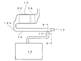
- an exhaust gas purification device 1 includes, in order from the upstream side, a diesel engine (hereinafter referred to as an engine) 10 that is an internal combustion engine, a connecting pipe 11 that leads exhaust gas discharged from the engine 10, and a front stage.
- pre-stage DOC oxidation catalyst
- DPF diesel particulate filter
- a mixer chamber 13 disposed, an exhaust pipe (second exhaust pipe section) 14 provided with a urea water injection device (reducing agent supply means) 16 at an upstream end, a selective reduction type NOx catalyst (hereinafter referred to as SCR) 33, and A post-stage post-treatment device (post-treatment device) 15 having a post-stage oxidation catalyst (hereinafter, post-stage DOC) 34 is provided.
- SCR selective reduction type NOx catalyst
- the connecting pipe 11, the pre-stage post-processing device 12, and the mixer chamber 13 according to the present embodiment constitute a first exhaust pipe section of the present invention.
- the connecting pipe 11 is connected to the exhaust manifold (not shown) of the engine 10 on the upstream side, and connected to the pre-stage post-processing device 12 via the bent portion 11a.
- the DPF 32 of the pre-stage post-processing device 12 collects particulate matter (hereinafter referred to as PM) in the exhaust gas flowing from the connection pipe 11.
- the DPF 32 is supplied with fuel to the upstream DOC31 provided upstream by exhaust injection from an exhaust pipe injection device (not shown) or post-injection of the engine 10, and the upstream DOC31 is heated by an oxidation reaction. Then, the deposited PM is removed by combustion.
- the mixer chamber 13 includes a pre-stage chamber portion 13 a connected to the downstream side of the pre-stage post-processing apparatus 12 and a post-stage chamber 13 portion b to which the exhaust pipe 14 is connected.
- a communication portion 13c for leading the exhaust gas from the front chamber portion 13a to the rear chamber portion 13b is provided between the front chamber portion 13a and the rear chamber portion 13b. That is, the mixer chamber 13 is integrally formed by the front chamber portion 13a, the communication portion 13c, and the rear chamber portion 13b arranged in order from the upstream side.
- two mounting holes 20 and 21 through which the upstream side surface portion 14a of the exhaust pipe 14 is inserted are formed in the wall surface portion of the rear chamber portion 13b.
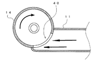
- three fins 13e, 13f, and 13g that rectify the flow of the exhaust gas toward the inlet window 40 are provided on the inner wall surface of the rear chamber portion 13b. The three fins 13e, 13f, and 13g cause the exhaust gas to flow into the inlet window 40 from the tangential direction of the exhaust pipe 14, thereby generating a swirling flow (arrow X in FIG. 2) in the exhaust gas in the cylinder of the exhaust pipe 14. .
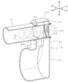
- the exhaust pipe (second exhaust pipe section) 14 is formed in a cylindrical shape as shown in FIGS. 3 and 4, and an inlet window (opening section) for introducing exhaust gas from the mixer chamber 13 into the upstream side surface section 14 a. ) 40 is provided.
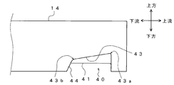
- the inlet window 40 includes a right edge 41 for the exhaust gas flow in the exhaust pipe 14 extending in the axial direction of the exhaust pipe 14 and an upstream edge 42 extending in the circumferential direction of the exhaust pipe 14. And a left side edge portion (first inclined side) 43 extending in the axial direction of the exhaust pipe 14 and a downstream side edge portion (second inclined side) 44 extending in the circumferential direction of the exhaust pipe 14.
- first inclined side first inclined side
- second inclined side second inclined side
- the left side edge (first inclined side) 43 is formed so as to extend in a direction inclined with respect to the axis of the exhaust pipe 14, as shown in FIG.
- the left side edge 43 is inclined so that the upstream end 43a is located above the downstream end 43b when the exhaust pipe 14 is viewed from the upstream side of the mixer chamber 13.
- the downstream side edge (second inclined side) 44 is formed to extend from one end of the left side edge 43 in a direction inclined with respect to the diameter of the exhaust pipe 14.
- the downstream edge 44 extends from the downstream end 43 b of the left edge 43 (hereinafter also referred to as the left end 43 b of the downstream edge 44) to the right edge 41 that is the opposite side of the left edge 43. It extends toward the downstream side of the exhaust pipe 14 and extends. That is, as shown in FIG. 4, when the entrance window 40 is viewed from above, the left end 43b of the downstream edge 44 is positioned upstream of the exhaust pipe 14 with respect to the right end 44c.
- a curved portion R having a larger radius of curvature than the other corners of the entrance window 40 is provided between the left side edge portion 43 and the downstream side edge portion 44.
- the left side edge 43 and the downstream side edge 44 are formed so as to be smoothly continuous.
- the upstream side surface portion 14 a of the exhaust pipe 14 is inserted into the mounting holes 20 and 21 of the mixer chamber 13 with the inlet window 40 facing downward. That is, the exhaust pipe 14 is connected to the rear chamber portion 13 b so that the axial direction of the exhaust pipe 14 is about 90 degrees with respect to the longitudinal direction of the mixer chamber 13.
- a downstream post-treatment device 15 is connected to the downstream side of the exhaust pipe 14 via a bent portion 14b.
- the urea water injection device (reducing agent supply means) 16 includes a urea water supply pipe, a urea water return pipe, a feed pump, a pressure control valve, a storage tank, etc. (not shown). Further, as shown in FIG. 4, the urea water injection device 16 has a fixing plate 61 attached to a heat insulating plate 60 fitted into the upstream cylinder of the exhaust pipe 14, and is fixed to the fixing plate 61 with a bolt or the like (not shown). As a result, it is provided at the upstream end of the exhaust pipe 14.
- the SCR 33 of the post-stage post-treatment device (post-treatment device) 15 promotes the reduction reaction of NOx contained in the exhaust gas flowing from the exhaust pipe 14. Specifically, urea water injected from the urea water injection device 16 is hydrolyzed by exhaust gas and generated into ammonia. The SCR 33 adsorbs the generated ammonia and reduces and purifies NOx with the ammonia adsorbed when the exhaust gas passes through the SCR 33.
- the post-stage DOC 34 disposed on the downstream side of the SCR 33 oxidizes and removes the excess ammonia from the exhaust gas.
- the exhaust gas purification apparatus 1 has the following operations and effects.
- the exhaust gas discharged from the engine 10 is introduced into the pre-stage post-treatment device 12 through the connection pipe 11.
- the exhaust gas flowing into the pre-stage post-processing device 12 is introduced into the mixer chamber 13 while PM in the exhaust gas is collected by the DPF 32.
- the exhaust gas flowing into the front chamber portion 13a of the mixer chamber 13 flows into the rear chamber portion 13b through the communication portion 13c, and is rectified by the plurality of fins 13e, 13f, 13g while being rectified. 40.
- the urea water injected from the urea water injection device 16 is mixed and diffused with air by the swirling flow (arrow X in FIG. 2), but some urea water swirls after adhering in the exhaust pipe 14 cylinder. (Arrow X in FIG. 2) flows toward the left edge 43.
- the urea water that has reached the vicinity of the left edge 43 remains in the vicinity of the left edge 43 due to the entrained flow (arrow Y in FIG. 2).
- the urea water adhering to the cylinder surface of the exhaust pipe 14 in the vicinity of the left side edge 43 moves to the curved part R along the left side edge 43 inclined with the upstream end 43a positioned below the downstream end 43b. Washed away. Thereafter, the urea water that has reached the curved portion R flows to the downstream edge 44 that is smoothly continuous by the curved portion R, and further flows downstream from the right end 44 c of the downstream end 44.
- the portion can be hydrolyzed by exhaust gas to produce ammonia and fed to the SCR 33.
- the exhaust pipe 14 has been described as being cylindrical.
- the exhaust pipe 14 is not necessarily cylindrical, and an exhaust pipe having a square cross section may be used.
- the post-stage post-treatment device 15 has been described as including the SCR 33.
- an occlusion reduction type NOx catalyst LNT
- LNT occlusion reduction type NOx catalyst
- the pre-stage post-treatment device 12 is not necessarily required.
- the pre-stage post-treatment device 12 and the mixer chamber 13 are omitted, and the intake manifold (non-exhaust manifold) of the engine 10 is connected to the connection pipe 11. It is also possible to connect the exhaust pipe 14 and the exhaust pipe 14 directly. Also in this case, the same effect as the above-described embodiment can be obtained.
Abstract
Description
10 エンジン(内燃機関)
11 接続管(第1の排気管部)
12 前段後処理装置(第1の排気管部)
13 ミキサーチャンバー(第1の排気管部)
14 排気管(第2の排気管部)
15 後段後処理装置
16 尿素水噴射装置(還元剤供給手段)
43 左側縁部(第1の傾斜辺)
44 下流側縁部(第2の傾斜辺)
R 曲線部
Claims (5)
- 内燃機関の排気系に還元剤によって排気ガス中の窒素化合物を還元浄化する後処理装置を有する排気ガス浄化装置において、
前記内燃機関から排出される排気ガスを導出する第1の排気管部と、
上流側の側部に前記第1の排気管部から排気ガスを導入する開口部を有するとともに、筒内で排気ガスに旋回流を生じるように、前記側部を前記第1の排気管部に接続され、下流側に前記後処理装置が設けられる第2の排気管部と、
前記第2の排気管部の上流端に設けられ、前記後処理装置に還元剤を供給する還元剤供給手段とを備え、
前記開口部は、前記第2の排気管部の軸に対して傾斜する方向に延びる少なくとも一辺の第1の傾斜辺を含んで形成される
ことを特徴とする排気ガス浄化装置。 - 前記開口部は、前記第1の傾斜辺の一端から前記第2の排気管部の径に対して傾斜する方向に延びる第2の傾斜辺をさらに含んで形成される
ことを特徴とする請求項1に記載の排気ガス浄化装置。 - 前記第1の傾斜辺と前記第2の傾斜辺とを滑らかに連続させるべく、前記第1の傾斜辺と前記第2の傾斜辺との間に曲線部を設けた
ことを特徴とする請求項2に記載の排気ガス浄化装置。 - 前記還元剤供給手段は還元剤として尿素水を噴射する
ことを特徴とする請求項1~3の何れかに記載の排気ガス浄化装置。 - 前記後処理装置は選択還元型NOx触媒と酸化触媒とを有する
ことを特徴とする請求項1~4の何れかに記載の排気ガス浄化装置。
Priority Applications (4)
| Application Number | Priority Date | Filing Date | Title |
|---|---|---|---|
| AU2011259481A AU2011259481B2 (en) | 2010-05-25 | 2011-05-16 | Exhaust gas purification device |
| CN201180024523.4A CN102892988B (zh) | 2010-05-25 | 2011-05-16 | 废气净化装置 |
| EP11786505.5A EP2578828B1 (en) | 2010-05-25 | 2011-05-16 | Exhaust gas purification device |
| US13/699,507 US8747761B2 (en) | 2010-05-25 | 2011-05-16 | Exhaust gas purification device |
Applications Claiming Priority (2)
| Application Number | Priority Date | Filing Date | Title |
|---|---|---|---|
| JP2010-119687 | 2010-05-25 | ||
| JP2010119687A JP5602495B2 (ja) | 2010-05-25 | 2010-05-25 | 排気ガス浄化装置 |
Publications (1)
| Publication Number | Publication Date |
|---|---|
| WO2011148806A1 true WO2011148806A1 (ja) | 2011-12-01 |
Family
ID=45003797
Family Applications (1)
| Application Number | Title | Priority Date | Filing Date |
|---|---|---|---|
| PCT/JP2011/061196 WO2011148806A1 (ja) | 2010-05-25 | 2011-05-16 | 排気ガス浄化装置 |
Country Status (6)
| Country | Link |
|---|---|
| US (1) | US8747761B2 (ja) |
| EP (1) | EP2578828B1 (ja) |
| JP (1) | JP5602495B2 (ja) |
| CN (1) | CN102892988B (ja) |
| AU (1) | AU2011259481B2 (ja) |
| WO (1) | WO2011148806A1 (ja) |
Cited By (3)
| Publication number | Priority date | Publication date | Assignee | Title |
|---|---|---|---|---|
| CN104040130A (zh) * | 2012-01-12 | 2014-09-10 | 日野自动车株式会社 | 排气净化装置 |
| CN104066942A (zh) * | 2013-01-17 | 2014-09-24 | 株式会社小松制作所 | 还原剂水溶液混合装置及具备它的废气后处理装置 |
| US9308495B2 (en) | 2012-07-25 | 2016-04-12 | Hino Motors, Ltd. | Exhaust purifier |
Families Citing this family (31)
| Publication number | Priority date | Publication date | Assignee | Title |
|---|---|---|---|---|
| US8916100B2 (en) | 2011-12-27 | 2014-12-23 | Komatsu Ltd. | Reducing agent aqueous solution mixing device and exhaust gas post-treatment device |
| US8932530B2 (en) | 2011-12-27 | 2015-01-13 | Komatsu Ltd. | Reducing agent aqueous solution mixing device and exhaust gas post-treatment device |
| JP5349575B2 (ja) | 2011-12-27 | 2013-11-20 | 株式会社小松製作所 | 還元剤水溶液ミキシング装置及び排気ガス後処理装置 |
| US9062589B2 (en) | 2013-01-17 | 2015-06-23 | Komatsu Ltd. | Reductant aqueous solution mixing device and exhaust aftertreatment device provided with the same |
| WO2014112073A1 (ja) | 2013-01-17 | 2014-07-24 | 株式会社小松製作所 | 還元剤水溶液ミキシング装置およびこれを備えた排気ガス後処理装置 |
| WO2014112063A1 (ja) | 2013-01-17 | 2014-07-24 | 株式会社小松製作所 | 還元剤水溶液ミキシング装置およびこれを備えた排気ガス後処理装置 |
| EP3205390B1 (en) * | 2013-02-15 | 2022-08-17 | Donaldson Company, Inc. | Dosing and mixing arrangement for use in exhaust aftertreatment |
| DE102013005206B3 (de) * | 2013-03-08 | 2014-06-26 | Eberspächer Exhaust Technology GmbH & Co. KG | Einströmkammer für einen Katalysator einer Abgasreinigungsanlage |
| GB2512934C (en) * | 2013-04-12 | 2020-03-11 | Eminox Ltd | Reductant injection in an exhaust system |
| EP2792864A1 (de) * | 2013-04-17 | 2014-10-22 | ROTH-TECHNIK AUSTRIA Gesellschaft m.b.H. | Abgasbehandlungseinrichtung für einen Abgasstrom einer Brennkraftmaschine |
| US10369533B2 (en) | 2013-09-13 | 2019-08-06 | Donaldson Company, Inc. | Dosing and mixing arrangement for use in exhaust aftertreatment |
| JP6185366B2 (ja) * | 2013-10-31 | 2017-08-23 | 日野自動車株式会社 | 排気浄化装置 |
| KR20160134640A (ko) * | 2014-03-20 | 2016-11-23 | 얀마 가부시키가이샤 | 엔진 장치 |
| DE202014102872U1 (de) * | 2014-06-10 | 2014-07-09 | Tenneco Gmbh | Abgasmischer |
| DE102014009015A1 (de) | 2014-06-17 | 2015-12-17 | Daimler Ag | Mischvorrichtung eines Abgasreinigungssystems einer Kraftfahrzeug-Brennkraftmaschine |
| DE102014009731A1 (de) | 2014-06-28 | 2015-12-31 | Daimler Ag | Reduktionsmittelaufbereitungssystem |
| JP2016188579A (ja) * | 2015-03-30 | 2016-11-04 | いすゞ自動車株式会社 | 排気浄化ユニット |
| WO2016158993A1 (ja) | 2015-03-30 | 2016-10-06 | いすゞ自動車株式会社 | 排気浄化ユニット |
| US9534525B2 (en) | 2015-05-27 | 2017-01-03 | Tenneco Automotive Operating Company Inc. | Mixer assembly for exhaust aftertreatment system |
| FR3040193B1 (fr) * | 2015-08-20 | 2019-07-19 | Psa Automobiles Sa. | Systeme de reduction catalytique selective |
| KR102520281B1 (ko) * | 2015-09-30 | 2023-04-12 | 로베르트 보쉬 게엠베하 | 스월 혼합형 배기가스 후처리 박스 및 시스템 |
| CN106762050A (zh) * | 2015-11-20 | 2017-05-31 | 罗伯特·博世有限公司 | 集成式尾气后处理系统 |
| JP6728782B2 (ja) * | 2016-03-03 | 2020-07-22 | いすゞ自動車株式会社 | 内燃機関の排ガス浄化装置 |
| CN107435576B (zh) * | 2016-05-27 | 2021-06-01 | 罗伯特·博世有限公司 | 集成的尾气后处理系统 |
| GB2539114A (en) * | 2016-07-05 | 2016-12-07 | Daimler Ag | Mixing device and aftertreatment device |
| JP2018071399A (ja) * | 2016-10-27 | 2018-05-10 | いすゞ自動車株式会社 | 配管ユニット |
| JP6891588B2 (ja) * | 2017-03-28 | 2021-06-18 | いすゞ自動車株式会社 | 内燃機関の排気浄化装置 |
| JP6894385B2 (ja) * | 2018-01-05 | 2021-06-30 | フタバ産業株式会社 | 混合装置 |
| JP6996382B2 (ja) | 2018-03-23 | 2022-01-17 | いすゞ自動車株式会社 | 排気浄化システムの劣化診断装置 |
| JP7243107B2 (ja) * | 2018-09-28 | 2023-03-22 | いすゞ自動車株式会社 | 排気構造及び車両 |
| CN116291834A (zh) * | 2023-03-22 | 2023-06-23 | 盐城工学院 | 一种高密度柴油机scr串联系统 |
Citations (4)
| Publication number | Priority date | Publication date | Assignee | Title |
|---|---|---|---|---|
| JP2009036109A (ja) | 2007-08-02 | 2009-02-19 | Hino Motors Ltd | 排気浄化装置 |
| JP2009228484A (ja) * | 2008-03-19 | 2009-10-08 | Tokyo Roki Co Ltd | 内燃機関用の排ガス浄化装置 |
| WO2009144766A1 (ja) * | 2008-05-27 | 2009-12-03 | 日野自動車株式会社 | 排気浄化装置 |
| JP2010019082A (ja) * | 2008-07-08 | 2010-01-28 | Mitsubishi Fuso Truck & Bus Corp | 内燃機関の排気浄化システム |
Family Cites Families (8)
| Publication number | Priority date | Publication date | Assignee | Title |
|---|---|---|---|---|
| DE4025017C2 (de) | 1990-08-07 | 1996-03-21 | Zeuna Staerker Kg | Abgasleitung mit einem Partikelfilter und einem Regenerierungsbrenner |
| DE4203807A1 (de) * | 1990-11-29 | 1993-08-12 | Man Nutzfahrzeuge Ag | Vorrichtung zur katalytischen no(pfeil abwaerts)x(pfeil abwaerts)-reduktion |
| CN1132653C (zh) * | 1999-12-29 | 2003-12-31 | 刘澄清 | 倾斜式同向流沉淀器 |
| JP2008051011A (ja) * | 2006-08-24 | 2008-03-06 | Toyota Motor Corp | 内燃機関の排気浄化システム |
| JP4928398B2 (ja) * | 2007-09-20 | 2012-05-09 | 日野自動車株式会社 | 排気浄化装置 |
| JP5017065B2 (ja) * | 2007-11-21 | 2012-09-05 | 日野自動車株式会社 | 排気浄化装置 |
| CN201152442Y (zh) * | 2007-12-28 | 2008-11-19 | 青岛嘉泓建材有限公司 | 叶片旋流排水导流接头 |
| JP5288372B2 (ja) | 2008-06-19 | 2013-09-11 | 国立大学法人広島大学 | 芳香族化合物の誘導体とそれらの中間体の製造方法 |
-
2010
- 2010-05-25 JP JP2010119687A patent/JP5602495B2/ja not_active Expired - Fee Related
-
2011
- 2011-05-16 EP EP11786505.5A patent/EP2578828B1/en not_active Not-in-force
- 2011-05-16 AU AU2011259481A patent/AU2011259481B2/en not_active Ceased
- 2011-05-16 CN CN201180024523.4A patent/CN102892988B/zh not_active Expired - Fee Related
- 2011-05-16 WO PCT/JP2011/061196 patent/WO2011148806A1/ja active Application Filing
- 2011-05-16 US US13/699,507 patent/US8747761B2/en active Active
Patent Citations (4)
| Publication number | Priority date | Publication date | Assignee | Title |
|---|---|---|---|---|
| JP2009036109A (ja) | 2007-08-02 | 2009-02-19 | Hino Motors Ltd | 排気浄化装置 |
| JP2009228484A (ja) * | 2008-03-19 | 2009-10-08 | Tokyo Roki Co Ltd | 内燃機関用の排ガス浄化装置 |
| WO2009144766A1 (ja) * | 2008-05-27 | 2009-12-03 | 日野自動車株式会社 | 排気浄化装置 |
| JP2010019082A (ja) * | 2008-07-08 | 2010-01-28 | Mitsubishi Fuso Truck & Bus Corp | 内燃機関の排気浄化システム |
Non-Patent Citations (1)
| Title |
|---|
| See also references of EP2578828A1 |
Cited By (6)
| Publication number | Priority date | Publication date | Assignee | Title |
|---|---|---|---|---|
| CN104040130A (zh) * | 2012-01-12 | 2014-09-10 | 日野自动车株式会社 | 排气净化装置 |
| EP2803833A4 (en) * | 2012-01-12 | 2015-09-16 | Hino Motors Ltd | DEVICE FOR PURIFYING EXHAUST GASES |
| US9604170B2 (en) | 2012-01-12 | 2017-03-28 | Hino Motors, Ltd. | Exhaust gas purification device |
| US9308495B2 (en) | 2012-07-25 | 2016-04-12 | Hino Motors, Ltd. | Exhaust purifier |
| CN104066942A (zh) * | 2013-01-17 | 2014-09-24 | 株式会社小松制作所 | 还原剂水溶液混合装置及具备它的废气后处理装置 |
| CN104066942B (zh) * | 2013-01-17 | 2015-09-16 | 株式会社小松制作所 | 还原剂水溶液混合装置及具备它的废气后处理装置 |
Also Published As
| Publication number | Publication date |
|---|---|
| CN102892988B (zh) | 2015-06-03 |
| US8747761B2 (en) | 2014-06-10 |
| EP2578828A1 (en) | 2013-04-10 |
| AU2011259481A1 (en) | 2012-12-20 |
| US20130064725A1 (en) | 2013-03-14 |
| AU2011259481B2 (en) | 2014-08-07 |
| EP2578828A4 (en) | 2016-03-09 |
| CN102892988A (zh) | 2013-01-23 |
| JP5602495B2 (ja) | 2014-10-08 |
| EP2578828B1 (en) | 2017-09-20 |
| JP2011247128A (ja) | 2011-12-08 |
Similar Documents
| Publication | Publication Date | Title |
|---|---|---|
| JP5602495B2 (ja) | 排気ガス浄化装置 | |
| JP5779410B2 (ja) | 車両の排気ガス後処理システム用ドージングモジュール | |
| JP6114305B2 (ja) | 排気後処理システム及びそのシステムを操作する方法 | |
| US8402754B2 (en) | Apparatus for purifying exhaust gas | |
| US8955312B2 (en) | Reductant aqueous solution mixing device and exhaust aftertreatment device provided with the same | |
| JP2008151088A (ja) | 排気浄化装置 | |
| EP3047123B1 (en) | Exhaust treatment apparatus and vehicle comprising the same | |
| WO2012008572A1 (ja) | 排気ガス浄化装置 | |
| JP4651560B2 (ja) | 内燃機関の排気浄化装置 | |
| KR20140023696A (ko) | 디젤 엔진의 배기가스 후처리 시스템 | |
| US20090100827A1 (en) | Exhaust gas purification apparatus for internal combustion engine | |
| JP2010163988A (ja) | 内燃機関の排気構造 | |
| JP2009091976A (ja) | 内燃機関の排気浄化装置 | |
| JP5567920B2 (ja) | 排気ガス浄化装置 | |
| KR101610061B1 (ko) | 차량의 배기 가스 정화장치 | |
| KR101474281B1 (ko) | Aoc촉매를 이용하여 암모니아 슬립을 정화하는 차량/엔진용 촉매정화장치 및 제어방법 | |
| JP2009162122A (ja) | 排気通路構造 | |
| JP2021143601A (ja) | 排気構造 | |
| JP2020041529A (ja) | 排気ガス浄化システム | |
| JP2009144680A (ja) | 排気浄化装置 | |
| JP2019011684A (ja) | 排気ガス浄化システム | |
| JP2012002084A (ja) | 排気流案内用ガイド及び排気流案内用ガイドを備える排気浄化装置 | |
| JP2009097439A (ja) | 排気浄化装置 |
Legal Events
| Date | Code | Title | Description |
|---|---|---|---|
| WWE | Wipo information: entry into national phase |
Ref document number: 201180024523.4 Country of ref document: CN |
|
| 121 | Ep: the epo has been informed by wipo that ep was designated in this application |
Ref document number: 11786505 Country of ref document: EP Kind code of ref document: A1 |
|
| WWE | Wipo information: entry into national phase |
Ref document number: 13699507 Country of ref document: US |
|
| NENP | Non-entry into the national phase |
Ref country code: DE |
|
| REEP | Request for entry into the european phase |
Ref document number: 2011786505 Country of ref document: EP |
|
| WWE | Wipo information: entry into national phase |
Ref document number: 2011786505 Country of ref document: EP |
|
| ENP | Entry into the national phase |
Ref document number: 2011259481 Country of ref document: AU Date of ref document: 20110516 Kind code of ref document: A |