WO2011132671A1 - バッテリ接続プレート - Google Patents
バッテリ接続プレート Download PDFInfo
- Publication number
- WO2011132671A1 WO2011132671A1 PCT/JP2011/059618 JP2011059618W WO2011132671A1 WO 2011132671 A1 WO2011132671 A1 WO 2011132671A1 JP 2011059618 W JP2011059618 W JP 2011059618W WO 2011132671 A1 WO2011132671 A1 WO 2011132671A1
- Authority
- WO
- WIPO (PCT)
- Prior art keywords
- signal output
- wiring
- battery
- connection plate
- output line
- Prior art date
- Legal status (The legal status is an assumption and is not a legal conclusion. Google has not performed a legal analysis and makes no representation as to the accuracy of the status listed.)
- Ceased
Links
Images


Classifications
-
- H—ELECTRICITY
- H01—ELECTRIC ELEMENTS
- H01M—PROCESSES OR MEANS, e.g. BATTERIES, FOR THE DIRECT CONVERSION OF CHEMICAL ENERGY INTO ELECTRICAL ENERGY
- H01M10/00—Secondary cells; Manufacture thereof
- H01M10/42—Methods or arrangements for servicing or maintenance of secondary cells or secondary half-cells
- H01M10/48—Accumulators combined with arrangements for measuring, testing or indicating the condition of cells, e.g. the level or density of the electrolyte
-
- H—ELECTRICITY
- H01—ELECTRIC ELEMENTS
- H01M—PROCESSES OR MEANS, e.g. BATTERIES, FOR THE DIRECT CONVERSION OF CHEMICAL ENERGY INTO ELECTRICAL ENERGY
- H01M50/00—Constructional details or processes of manufacture of the non-active parts of electrochemical cells other than fuel cells, e.g. hybrid cells
- H01M50/50—Current conducting connections for cells or batteries
- H01M50/502—Interconnectors for connecting terminals of adjacent batteries; Interconnectors for connecting cells outside a battery casing
- H01M50/507—Interconnectors for connecting terminals of adjacent batteries; Interconnectors for connecting cells outside a battery casing comprising an arrangement of two or more busbars within a container structure, e.g. busbar modules
-
- H—ELECTRICITY
- H01—ELECTRIC ELEMENTS
- H01M—PROCESSES OR MEANS, e.g. BATTERIES, FOR THE DIRECT CONVERSION OF CHEMICAL ENERGY INTO ELECTRICAL ENERGY
- H01M50/00—Constructional details or processes of manufacture of the non-active parts of electrochemical cells other than fuel cells, e.g. hybrid cells
- H01M50/50—Current conducting connections for cells or batteries
- H01M50/502—Interconnectors for connecting terminals of adjacent batteries; Interconnectors for connecting cells outside a battery casing
- H01M50/514—Methods for interconnecting adjacent batteries or cells
- H01M50/517—Methods for interconnecting adjacent batteries or cells by fixing means, e.g. screws, rivets or bolts
-
- H—ELECTRICITY
- H01—ELECTRIC ELEMENTS
- H01M—PROCESSES OR MEANS, e.g. BATTERIES, FOR THE DIRECT CONVERSION OF CHEMICAL ENERGY INTO ELECTRICAL ENERGY
- H01M50/00—Constructional details or processes of manufacture of the non-active parts of electrochemical cells other than fuel cells, e.g. hybrid cells
- H01M50/50—Current conducting connections for cells or batteries
- H01M50/502—Interconnectors for connecting terminals of adjacent batteries; Interconnectors for connecting cells outside a battery casing
- H01M50/521—Interconnectors for connecting terminals of adjacent batteries; Interconnectors for connecting cells outside a battery casing characterised by the material
- H01M50/524—Organic material
-
- H—ELECTRICITY
- H01—ELECTRIC ELEMENTS
- H01M—PROCESSES OR MEANS, e.g. BATTERIES, FOR THE DIRECT CONVERSION OF CHEMICAL ENERGY INTO ELECTRICAL ENERGY
- H01M50/00—Constructional details or processes of manufacture of the non-active parts of electrochemical cells other than fuel cells, e.g. hybrid cells
- H01M50/20—Mountings; Secondary casings or frames; Racks, modules or packs; Suspension devices; Shock absorbers; Transport or carrying devices; Holders
- H01M50/204—Racks, modules or packs for multiple batteries or multiple cells
- H01M50/207—Racks, modules or packs for multiple batteries or multiple cells characterised by their shape
- H01M50/209—Racks, modules or packs for multiple batteries or multiple cells characterised by their shape adapted for prismatic or rectangular cells
-
- Y—GENERAL TAGGING OF NEW TECHNOLOGICAL DEVELOPMENTS; GENERAL TAGGING OF CROSS-SECTIONAL TECHNOLOGIES SPANNING OVER SEVERAL SECTIONS OF THE IPC; TECHNICAL SUBJECTS COVERED BY FORMER USPC CROSS-REFERENCE ART COLLECTIONS [XRACs] AND DIGESTS
- Y02—TECHNOLOGIES OR APPLICATIONS FOR MITIGATION OR ADAPTATION AGAINST CLIMATE CHANGE
- Y02E—REDUCTION OF GREENHOUSE GAS [GHG] EMISSIONS, RELATED TO ENERGY GENERATION, TRANSMISSION OR DISTRIBUTION
- Y02E60/00—Enabling technologies; Technologies with a potential or indirect contribution to GHG emissions mitigation
- Y02E60/10—Energy storage using batteries
Definitions
- the present invention relates to a battery connection plate attached to a battery mounted on a vehicle such as an electric vehicle or a hybrid car.
- Electric cars and hybrid cars are increasing as environmentally friendly cars.
- a power supply device including a battery assembly in which a plurality of batteries are stacked.
- This type of power supply device has a battery assembly in which batteries having a positive electrode at one end and a negative electrode at the other end are alternately stacked in the opposite direction, and the batteries are connected in series.
- the battery bar is provided with a bus bar having two holes through which the electrodes of the adjacent battery are inserted in the synthetic resin substrate portion, and serves as a connection portion for the battery.
- a flexible part is formed through a relief hole in a slit provided in the substrate part in order to adjust the positional deviation between the electrode and the hole of the bus bar for each predetermined number of connection parts.
- the board part is divided by slits, and both sides of each board part are connected by a pair of hinge-like flexible parts, or the board part is divided for each connection part, and each connection part is separated by a hinge-like flexible part.
- this misalignment is accumulated from the battery assembly start end to the assembly end end, so that there is a large shift at the assembly end end, and a large tension acts on the connected signal output line or a signal output. There was a risk that it would be difficult to connect the wires.
- the present invention has been made in view of the above-described circumstances, and an object of the present invention is to provide a battery connection plate that can suppress the influence on the signal output line due to the displacement of the connection position as much as possible and maintain a good wiring state. Is to provide.
- a battery connection plate having a plurality of bus bars provided on the substrate unit, attached to a battery assembly in which a plurality of batteries are sequentially stacked, and connected to the terminals of the battery, A window portion through which a plurality of signal output lines connected to the bus bar can be wired in the board portion, and a boss can be inserted into a wiring path of the signal output lines in the wiring material attachment portion.
- the signal output line is routed so as to bypass the boss inserted through the window portion or wound around the boss, and the boss is removed from the window portion.
- a battery connection plate in which a long part is formed.
- the battery connection plate having the configuration of (1) above it is extremely easy to route the signal output line so as to bypass the boss inserted into the window portion or to wind around the boss and to remove the boss from the window portion.
- a surplus portion can be formed in the signal output line.
- the extra length portion is formed in the signal output line in this way, even when the connection position of the signal output line to the bus bar is shifted due to the dimensional tolerance of the battery terminal when it is mounted on the battery assembly, The shift can be reliably absorbed by the extra length portion.
- the wiring material mounting portion has a wiring space for the signal output line wired from the battery assembly start end to the connection portion with the bus bar, and the wiring space is an end of battery assembly.
- the area gradually decreases, and the window portion reduces the wiring space toward the end of assembly, thereby reducing the signal output line. Is formed in a range including a region that is not to be wired and gradually increased.
- the window portion through which the boss is inserted includes a region where the signal output line becomes unwired due to a decrease in the wiring space toward the end of assembly. Since it is formed in the range and is gradually enlarged, the thickness of the boss inserted through the window portion can be increased. Thereby, the surplus part formed by the boss can be gradually lengthened from the assembly start end toward the assembly end end.
- the displacement of the connection position gradually increases from the battery assembly start end to the assembly end end.
- the extra length portion extends from the assembly start end to the assembly end end. Since the length can be gradually increased, the displacement can be reliably absorbed by the extra length portion regardless of the assembly position.
- by reducing the wiring space toward the end of assembly it is possible to effectively use the area where the signal output line is not wired, and it is possible to cope with misalignment without causing an increase in cost.
- a battery connection plate by reducing the wiring space toward the end of assembly, it is possible to effectively use the area where the signal output line is not wired, and it is possible to cope with mis
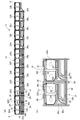
- FIG. 2A is a plan view of the whole battery connection plate according to the embodiment of the present invention
- FIG. 2B is a plan view of a part of the battery connection plate shown in FIG.
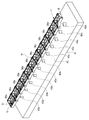
- It is a perspective view of a battery connection plate and a jig for wiring.
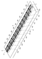
- It is a perspective view of the battery connection plate placed on the wiring jig.
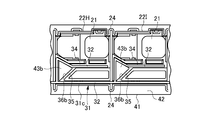
- It is a top view explaining the wiring method of the signal output line to a battery connection plate.
- It is a top view explaining the other wiring method of the signal output line to a battery connection plate.
- FIG. 8A is a plan view of the whole battery connection plate according to the reference example
- FIG. 8B is a plan view of a part of the battery connection plate according to the reference example shown in FIG.
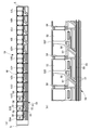
- the battery connection plate 11 is attached to the battery assembly 12.
- the battery assembly 12 is configured by assembling a plurality of rectangular batteries 13 so as to overlap from the assembly start end S toward the assembly end E.
- the terminals 14 of the respective batteries 13 are arranged on both side portions on the upper surface, and the battery connection plate 11 is attached to each arrangement place of these terminals 14.
- the battery connection plate 11 has a plurality of bus bar mounting portions 21 on a substrate portion 10 molded from a synthetic resin, and the bus bar mounting portions 21 include bus bars 20 (see FIG. 2 (b) is shown in FIG. A pair of connection holes 20 a are formed in these bus bars 20, and terminals 14 of a plurality of batteries 13 arranged in an overlapping manner are inserted into these connection holes 20 a. Then, by fastening a nut (not shown) to the terminal 14 of the battery 13, the terminal 14 is connected to the bus bar 20 of the battery connection plate 11.
- the substrate portion 10 of the battery connection plate 11 is divided into a plurality of divided bodies 22A to 22L in the longitudinal direction, and the divided bodies 22A to 22L are divided.
- a bus bar mounting portion 21 into which the bus bar 20 is fitted is formed in each.
- the divided bodies 22A to 22L are connected to each other by a pair of hinge parts 24. These hinge portions 24 are bent in a U-shape, so that the divided bodies 22A to 22L can be brought close to and away from each other when the hinge portions 24 are elastically deformed. That is, the battery connection plate 11 is provided with a pitch adjusting means including the hinge portion 24, and the hinge portion 24 absorbs the positional deviation of the terminals of the battery 13.
- the board part 10 of the battery connection plate 11 is provided with a wiring material mounting part 31 in parallel with the arrangement of the bus bar mounting parts 21.
- a plurality of signal output lines 32 for detecting the voltage of each battery 13 are mounted on the wiring member mounting portion 31. These signal output lines 32 are extended to the divided bodies 22A to 22L, and these divided sections are divided.
- the bus bar 20 is connected to the bus bar mounting portion 21 of the bodies 22A to 22L.
- the signal output line 32 is connected to a control device (not shown).
- the signal output line 32 is wired from the assembly start end S of the battery connection plate 11 to the wiring material mounting portion 31 and guided to the connection location with each bus bar 20.
- the wiring material mounting portion 31 has a plurality of signal line accommodation grooves (wiring spaces) 33a, 33b, 33c in which the signal output lines 32 are accommodated.
- the signal line accommodation groove 33a is formed over the divided bodies 22A to 22C
- the signal line accommodation groove 33b is formed over the divided bodies 22A to 22G
- the signal line accommodation groove 33c is formed over the divided bodies 22A to 22K.
- Each of the divided bodies 22A to 22L is formed with a branch line 34 connected to the connection point with the bus bar 20.
- the wiring space including the signal line housing grooves 33 a, 33 b, and 33 c extends toward the assembly end terminal E of the battery 13. As the value decreases, the area gradually decreases.
- Three signal output lines 32 are accommodated in the signal line accommodating groove 33a so as to be stacked one above the other, and these signal output lines 32 are guided to the branch lines 34 of the divided bodies 22B to 22C. Connected to the bus bar 20 mounted on the bus bar mounting portion 21 of the divided bodies 22B to 22C.
- signal line accommodating groove 33b In the signal line accommodating groove 33b, four signal output lines 32 are accommodated so as to be stacked one above the other, and these signal output lines 32 are guided to the branch lines 34 of the divided bodies 22D to 22G. It is connected to the bus bar 20 mounted on the bus bar mounting portion 21 of the divided bodies 22D to 22G.
- Signal output lines 32 are accommodated in the signal line accommodating groove 33c so as to be stacked one above the other, and these signal output lines 32 are guided to the branch lines 34 of the divided bodies 22H to 22L. Connected to the bus bar 20 mounted on the bus bar mounting portion 21 of the divided bodies 22H to 22L.
- one signal output line 32 is directly led to the branch line 34 to the divided body 22A, and this signal output line 32 is connected to the bus bar 20 mounted on the bus bar mounting portion 21 of the divided body 22A.
- Extra length accommodating portions 35 are formed in the wiring paths between the divided lines 22H to 22L and the branch lines 34, respectively. These surplus length accommodating portions 35 accommodate surplus length portions 32a in which the signal output lines 32 led to the branch lines 34 are slackened.
- a window portion 36a having a triangular shape in plan view penetrating the front and back is formed.
- the surplus length accommodating portion 35 of each of the divided bodies 22D to 22G is formed with a window portion 36b having a triangular shape in plan view that penetrates the front and back surfaces.
- the surplus length accommodating portion 35 of the divided bodies 22H to 22K is formed with a window portion 36c having a triangular shape in plan view that penetrates the front and back surfaces.
- the surplus length accommodating portion 35 of the divided body 22L is formed with a window portion 36d having a triangular shape in plan view that penetrates the front and back surfaces.
- the window 36d is not limited to a triangular shape in plan view, but may be a polygonal shape or a circular shape.
- the window areas 36b of the divided bodies 22D to 22G arranged closer to the assembly end E than the divided bodies 22B to 22C have a larger opening area than the window portions 36a of the divided bodies 22B to 22C.
- the opening portions 36c of the divided bodies 22H to 22K arranged on the assembling end E side of the divided bodies 22D to 22G have a larger opening area than the window portions 36b of the divided bodies 22D to 22G.
- the window 36d of the divided body 22L has a larger opening area than the window portions 36c of the divided bodies 22H to 22K.
- the window portions 36a, 36b, 36c, and 36d are arranged so that the signal output line 32 is not wired because the wiring space including the signal line receiving grooves 33a, 33b, and 33c decreases toward the assembly end E.
- the area of the opening is gradually increased and the opening area is gradually increased.
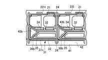
- a wiring jig 41 is used to wire the signal output line 32 to the wiring material mounting portion 31 of the substrate portion 10 in the battery connection plate 11.
- the wiring jig 41 has a mounting surface 42 on which the substrate part 10 of the battery connection plate 11 is mounted.
- the wiring of the signal output line 32 is the mounting surface 42 of the wiring jig 41.
- the battery connection plate 11 is placed on the battery.
- Boss 43a, 43b, 43c, 43d having a triangular shape in plan view is erected on the mounting surface 42.
- the boss 43a is formed at a position corresponding to the window portion 36a formed in the surplus length accommodating portion 35 of the divided bodies 22B to 22C.
- the boss 43b is formed at a position corresponding to the window portion 36b formed in the surplus length accommodating portion 35 of the divided bodies 22D to 22G.
- the boss 43c is formed at a position corresponding to the window portion 36c formed in the extra length accommodating portion 35 of the divided bodies 22H to 22K.
- the boss 43d is formed at a position corresponding to the window portion 36d formed in the surplus length accommodating portion 35 of the divided body 22L.
- the boss 43a has a slightly smaller cross-sectional shape than the window portion 36a formed in the extra length accommodating portion 35 of the divided bodies 22B to 22C.
- the boss 43b has a slightly smaller cross-sectional shape than the window portion 36b formed in the surplus length accommodating portion 35 of the divided bodies 22D to 22G.
- the boss 43c has a slightly smaller cross-sectional shape than the window portion 36c formed in the extra length accommodating portion 35 of the divided bodies 22H to 22K.
- the boss 43d has a cross-sectional shape slightly smaller than the window portion 36d formed in the extra length accommodating portion 35 of the divided body 22L.
- the boss 43a can be inserted into the window 36a with almost no gap
- the boss 43b can be inserted into the window 36b with almost no gap
- the boss 43c can be inserted into the window 36c with almost no gap
- the boss 43d can be inserted through the window 36d with almost no gap.
- the substrate portion 10 of the battery connection plate 11 and the bosses 43a, 43b, 43c, 43d of the wiring jig 41 are connected to the window portions 36a, 36b. , 36c, 36d, and placed on the placement surface 42.
- the battery connection plate 11 is positioned on the mounting surface 42 of the wiring jig 41 by the bosses 43a, 43b, 43c, 43d.
- the signal output line 32 is accommodated and wired in the signal line accommodating grooves 33a, 33b, 33c and the branch lines 34 of the divided bodies 22A to 22L.
- the signal output line 32 when the signal output line 32 is wired from the signal line accommodating grooves 33 a, 33 b, 33 c to the branch line 34, the signal output line 32 is connected to each boss 43 a separated from the branch line 34. , 43b, 43c, 43d.
- the battery 13 is mounted when the battery assembly 12 is mounted. Even if a displacement occurs in the connection position of the signal output line 32 to the bus bar 20 due to the dimensional tolerance of the terminal 14, the displacement can be reliably absorbed by the extra length portion 32a.
- the signal output line 32 becomes unwired. Since it is formed in a range including the region and gradually increased, the thickness of the bosses 43a, 43b, 43c, and 43d inserted into the window portions 36a, 36b, 36c, and 36d can be increased. Thereby, the surplus length part 32a formed by the bosses 43a, 43b, 43c, and 43d can be gradually increased from the assembly start end S toward the assembly end end E.
- the displacement of the connection position gradually increases from the assembly start end S of the battery 13 toward the assembly end E.
- the excess length portion 32a is moved from the assembly start end S. Since the length can be gradually increased toward the assembly end E, the displacement can be reliably absorbed by the extra length portion 32a regardless of the assembly position.
- the wiring space decreases toward the assembly end E, the area where the signal output line 32 is not wired can be used effectively, and it is possible to improve the positional deviation without increasing the cost.
- the battery connection plate 11 can be used.
- the battery connection plate 11 it is possible to eliminate such a problem that a large tension acts on the signal output line 32 due to a shift in the connection position or the signal output line 32 cannot be connected at the connection position with the bus bar 20. it can.
- the substrate portion 10 of the battery connection plate 11 is mounted on the wiring jig 41 while the bosses 43a, 43b, 43c, 43d of the wiring jig 41 are inserted through the window portions 36a, 36b, 36c, 36d.
- the battery connection plate 11 can be held and positioned very easily. Thereby, wiring workability
- the signal output line 32 when the signal output line 32 is wired from the signal line receiving grooves 33 a, 33 b, 33 c in the substrate unit 10 to the branch line 34, the signal output line 32 is connected to each boss 43 a, 43 b with respect to the branch line 34. , 43c, and 43d, the extra length portion 32a is formed by detouring to the outside, but in order to make the extra length portion 32a more slack, the signal output line 32 is connected to each boss as shown in FIG. What is necessary is just to wind around 43a, 43b, 43c, 43d. In this way, as shown in FIG.
- the surplus length portion 32 a having a large slack can be formed in the surplus length accommodating portion 35. It can be set as the battery connection plate 11 which can respond to a bigger shift
- FIGS. 8 (a) and 8 (b) reference examples are shown in FIGS. 8 (a) and 8 (b).
- FIG. 8A is a plan view of the entire battery plate according to the reference example
- FIG. 8B is a plan view of a part of the battery connection plate according to the reference example shown in FIG.
- the substrate portion 50 in the battery connection plate 51 has a plurality of divided bodies 53A to 53L each having a bus bar mounting portion 52 connected by a hinge portion.
- the substrate portion 50 of the battery connection plate 51 is provided with a wiring material mounting portion 56 having a plurality of signal line accommodation grooves 55, and a signal output line is provided in the signal line accommodation groove 55 of the wiring material attachment portion 56. 57 is accommodated.
- Each of the divided bodies 53A to 53L is formed with a branch line 58 that guides the signal output line 57 from the signal line receiving groove 55 to a connection point with a bus bar (not shown) mounted on the bus bar mounting portion 52.
- the signal output line 57 from the signal line accommodation groove 55 is accommodated in the line 58 without any extra length.
- the hinge portion 54 between the divided bodies 53 ⁇ / b> A to 53 ⁇ / b> L is deformed, so that the shift of the terminal 14 of the battery 13 is absorbed, and the bus bar attached to the bus bar attachment portion 52 is connected to the battery 13.
- the terminal 14 can be smoothly connected.
- this battery connection plate 51 does not have a surplus length in the signal output line 57, it is not possible to absorb the positional deviation of the terminal 14 of the battery 13. In particular, at the assembly end E of the battery 13 in which the deviation becomes large, a large tension may be applied to the connected signal output line 57 or the connection of the signal output line 57 may be difficult.
- the extra length can be formed in the signal output line very easily, and the influence on the signal output line due to the displacement of the connection position is suppressed as much as possible to maintain a good wiring state. be able to. Therefore, it is possible to provide a good battery connection plate that is attached to a battery mounted on a vehicle such as an electric vehicle or a hybrid car.
Landscapes
- Chemical & Material Sciences (AREA)
- Chemical Kinetics & Catalysis (AREA)
- Electrochemistry (AREA)
- General Chemical & Material Sciences (AREA)
- Engineering & Computer Science (AREA)
- Manufacturing & Machinery (AREA)
- Connection Of Batteries Or Terminals (AREA)
- Battery Mounting, Suspending (AREA)
Priority Applications (3)
| Application Number | Priority Date | Filing Date | Title |
|---|---|---|---|
| DE112011101401T DE112011101401T5 (de) | 2010-04-22 | 2011-04-19 | Batterieverbindungsplatte |
| CN201180004140.0A CN102576841B (zh) | 2010-04-22 | 2011-04-19 | 电池连接板 |
| US13/496,991 US8603661B2 (en) | 2010-04-22 | 2011-04-19 | Battery connection plate |
Applications Claiming Priority (2)
| Application Number | Priority Date | Filing Date | Title |
|---|---|---|---|
| JP2010-099197 | 2010-04-22 | ||
| JP2010099197A JP5524697B2 (ja) | 2010-04-22 | 2010-04-22 | バッテリ接続プレート |
Publications (1)
| Publication Number | Publication Date |
|---|---|
| WO2011132671A1 true WO2011132671A1 (ja) | 2011-10-27 |
Family
ID=44834190
Family Applications (1)
| Application Number | Title | Priority Date | Filing Date |
|---|---|---|---|
| PCT/JP2011/059618 Ceased WO2011132671A1 (ja) | 2010-04-22 | 2011-04-19 | バッテリ接続プレート |
Country Status (5)
| Country | Link |
|---|---|
| US (1) | US8603661B2 (enExample) |
| JP (1) | JP5524697B2 (enExample) |
| CN (1) | CN102576841B (enExample) |
| DE (1) | DE112011101401T5 (enExample) |
| WO (1) | WO2011132671A1 (enExample) |
Cited By (4)
| Publication number | Priority date | Publication date | Assignee | Title |
|---|---|---|---|---|
| JP2013051190A (ja) * | 2011-08-01 | 2013-03-14 | Yazaki Corp | 組電池用接続制御体 |
| WO2013061871A1 (ja) * | 2011-10-28 | 2013-05-02 | 株式会社オートネットワーク技術研究所 | 電池用配線モジュール |
| WO2014181806A1 (ja) * | 2013-05-07 | 2014-11-13 | 矢崎総業株式会社 | バスバモジュール及び電源装置 |
| WO2016042848A1 (ja) * | 2014-09-19 | 2016-03-24 | 株式会社豊田自動織機 | 電池モジュール |
Families Citing this family (18)
| Publication number | Priority date | Publication date | Assignee | Title |
|---|---|---|---|---|
| JP5809465B2 (ja) | 2011-07-05 | 2015-11-11 | 矢崎総業株式会社 | 電線配索装置 |
| WO2013084941A1 (ja) * | 2011-12-09 | 2013-06-13 | 本田技研工業株式会社 | バッテリモジュール |
| JP5945435B2 (ja) * | 2012-03-16 | 2016-07-05 | 本田技研工業株式会社 | バッテリモジュール |
| JP5938249B2 (ja) * | 2012-03-27 | 2016-06-22 | 本田技研工業株式会社 | 電動式鞍乗り型車両のバッテリユニット |
| JP5973262B2 (ja) * | 2012-07-09 | 2016-08-23 | 矢崎総業株式会社 | バスバモジュール |
| JP6047343B2 (ja) * | 2012-08-30 | 2016-12-21 | 矢崎総業株式会社 | バスバーモジュール用収容部 |
| JP2014060044A (ja) * | 2012-09-18 | 2014-04-03 | Auto Network Gijutsu Kenkyusho:Kk | 電池用配線モジュール |
| JP6186922B2 (ja) * | 2013-06-18 | 2017-08-30 | 住友電装株式会社 | 配線モジュール |
| JP6202338B2 (ja) | 2014-04-25 | 2017-09-27 | 株式会社オートネットワーク技術研究所 | 配線モジュール、配線モジュール中間体、及び配線モジュールの製造方法 |
| JP6245159B2 (ja) * | 2014-12-17 | 2017-12-13 | 株式会社オートネットワーク技術研究所 | 電池配線モジュール |
| JP6434468B2 (ja) * | 2016-09-30 | 2018-12-05 | 株式会社オートネットワーク技術研究所 | 接続モジュール |
| JP6469062B2 (ja) * | 2016-09-30 | 2019-02-13 | 株式会社オートネットワーク技術研究所 | 接続モジュール |
| JP6772937B2 (ja) * | 2017-04-10 | 2020-10-21 | 株式会社オートネットワーク技術研究所 | 蓄電パックのベースプレート構造、および蓄電パック |
| US10615396B2 (en) * | 2017-09-08 | 2020-04-07 | Molex, Llc | Battery connection module |
| KR101959912B1 (ko) * | 2018-06-12 | 2019-03-19 | 주식회사 경신 | 배터리팩 장착형 와이어링 프로텍터 |
| KR101959913B1 (ko) * | 2018-06-12 | 2019-03-19 | 주식회사 경신 | 배터리팩 장착형 와이어링 프로텍터 |
| KR101959911B1 (ko) * | 2018-06-12 | 2019-03-19 | 주식회사 경신 | 배터리팩 장착형 와이어링 프로텍터 |
| KR20230102738A (ko) * | 2021-12-30 | 2023-07-07 | 삼성에스디아이 주식회사 | 버스 바 홀더, 버스 바 조립체 및 전지 모듈 |
Citations (5)
| Publication number | Priority date | Publication date | Assignee | Title |
|---|---|---|---|---|
| JP2000333343A (ja) * | 1999-05-18 | 2000-11-30 | Yazaki Corp | バッテリ接続プレートとその製造方法 |
| JP2003242950A (ja) * | 2002-02-18 | 2003-08-29 | Shin Kobe Electric Mach Co Ltd | 組電池 |
| JP2010055885A (ja) * | 2008-08-27 | 2010-03-11 | Yazaki Corp | 電源装置 |
| JP2010170884A (ja) * | 2009-01-23 | 2010-08-05 | Yazaki Corp | バスバモジュール、及び、バスバモジュールの組み立て方法 |
| JP2011018478A (ja) * | 2009-07-07 | 2011-01-27 | Autonetworks Technologies Ltd | 電池接続アセンブリ |
Family Cites Families (6)
| Publication number | Priority date | Publication date | Assignee | Title |
|---|---|---|---|---|
| JP3343888B2 (ja) * | 1997-10-13 | 2002-11-11 | トヨタ自動車株式会社 | バッテリーホルダ用接続プレートおよびその製造方法 |
| JP3707595B2 (ja) * | 1998-09-09 | 2005-10-19 | 矢崎総業株式会社 | バッテリ接続プレート |
| CN2676420Y (zh) * | 2003-09-17 | 2005-02-02 | 扬州市正和电源有限公司 | 蓄电池连接板 |
| JP4686166B2 (ja) * | 2004-10-22 | 2011-05-18 | 矢崎総業株式会社 | バッテリ用樹脂カバーの電線配索構造 |
| JP2010099197A (ja) | 2008-10-22 | 2010-05-06 | Yamaha Corp | 机 |
| JP5223607B2 (ja) * | 2008-11-10 | 2013-06-26 | 株式会社デンソー | 電池パックの高電圧検出モジュール装置 |
-
2010
- 2010-04-22 JP JP2010099197A patent/JP5524697B2/ja active Active
-
2011
- 2011-04-19 DE DE112011101401T patent/DE112011101401T5/de not_active Withdrawn
- 2011-04-19 US US13/496,991 patent/US8603661B2/en active Active
- 2011-04-19 WO PCT/JP2011/059618 patent/WO2011132671A1/ja not_active Ceased
- 2011-04-19 CN CN201180004140.0A patent/CN102576841B/zh active Active
Patent Citations (5)
| Publication number | Priority date | Publication date | Assignee | Title |
|---|---|---|---|---|
| JP2000333343A (ja) * | 1999-05-18 | 2000-11-30 | Yazaki Corp | バッテリ接続プレートとその製造方法 |
| JP2003242950A (ja) * | 2002-02-18 | 2003-08-29 | Shin Kobe Electric Mach Co Ltd | 組電池 |
| JP2010055885A (ja) * | 2008-08-27 | 2010-03-11 | Yazaki Corp | 電源装置 |
| JP2010170884A (ja) * | 2009-01-23 | 2010-08-05 | Yazaki Corp | バスバモジュール、及び、バスバモジュールの組み立て方法 |
| JP2011018478A (ja) * | 2009-07-07 | 2011-01-27 | Autonetworks Technologies Ltd | 電池接続アセンブリ |
Cited By (7)
| Publication number | Priority date | Publication date | Assignee | Title |
|---|---|---|---|---|
| JP2013051190A (ja) * | 2011-08-01 | 2013-03-14 | Yazaki Corp | 組電池用接続制御体 |
| WO2013061871A1 (ja) * | 2011-10-28 | 2013-05-02 | 株式会社オートネットワーク技術研究所 | 電池用配線モジュール |
| JP2013097896A (ja) * | 2011-10-28 | 2013-05-20 | Auto Network Gijutsu Kenkyusho:Kk | 電池用配線モジュール |
| WO2014181806A1 (ja) * | 2013-05-07 | 2014-11-13 | 矢崎総業株式会社 | バスバモジュール及び電源装置 |
| JP2014220068A (ja) * | 2013-05-07 | 2014-11-20 | 矢崎総業株式会社 | バスバモジュール及び電源装置 |
| WO2016042848A1 (ja) * | 2014-09-19 | 2016-03-24 | 株式会社豊田自動織機 | 電池モジュール |
| JP2016062800A (ja) * | 2014-09-19 | 2016-04-25 | 株式会社豊田自動織機 | 電池モジュール |
Also Published As
| Publication number | Publication date |
|---|---|
| DE112011101401T5 (de) | 2013-04-25 |
| CN102576841B (zh) | 2014-11-12 |
| CN102576841A (zh) | 2012-07-11 |
| JP5524697B2 (ja) | 2014-06-18 |
| US8603661B2 (en) | 2013-12-10 |
| US20120183833A1 (en) | 2012-07-19 |
| JP2011228218A (ja) | 2011-11-10 |
Similar Documents
| Publication | Publication Date | Title |
|---|---|---|
| JP5524697B2 (ja) | バッテリ接続プレート | |
| JP6691178B2 (ja) | プロテクタ、及び、バスバモジュール | |
| JP6151476B2 (ja) | 電源装置 | |
| JP6118176B2 (ja) | バスバモジュール及び電源装置 | |
| JP5506307B2 (ja) | 電線配索装置 | |
| US11056753B2 (en) | Bus bar module | |
| WO2014181820A1 (ja) | バスバモジュール | |
| JP6202338B2 (ja) | 配線モジュール、配線モジュール中間体、及び配線モジュールの製造方法 | |
| CN110707277B (zh) | 电路体、汇流条和电子元件间的连接结构 | |
| US10840496B2 (en) | Bus bar module and power supply device | |
| JP6286141B2 (ja) | バスバモジュール及び電源装置 | |
| JP7256079B2 (ja) | 電線保持構造及びバスバーモジュール | |
| EP3754748B1 (en) | Electric wire holding structure and bus bar module | |
| WO2018225607A1 (ja) | 自動車用バスバモジュール及び電源装置 | |
| JP5437760B2 (ja) | 電気接続箱及びこの電気接続箱を備えた電源装置 | |
| WO2014034801A1 (ja) | 電圧検出用端子の保持構造 | |
| JP6118178B2 (ja) | バスバモジュール及び電源装置 | |
| JP5601226B2 (ja) | 端子台 | |
| US20180358796A1 (en) | Cable extra length absorbing structure and bus bar module | |
| WO2021075165A1 (ja) | 配線モジュール | |
| US10050242B2 (en) | Power supply device | |
| JP2021068695A (ja) | 配線モジュール |
Legal Events
| Date | Code | Title | Description |
|---|---|---|---|
| WWE | Wipo information: entry into national phase |
Ref document number: 201180004140.0 Country of ref document: CN |
|
| 121 | Ep: the epo has been informed by wipo that ep was designated in this application |
Ref document number: 11772006 Country of ref document: EP Kind code of ref document: A1 |
|
| WWE | Wipo information: entry into national phase |
Ref document number: 13496991 Country of ref document: US |
|
| WWE | Wipo information: entry into national phase |
Ref document number: 112011101401 Country of ref document: DE Ref document number: 1120111014015 Country of ref document: DE |
|
| 122 | Ep: pct application non-entry in european phase |
Ref document number: 11772006 Country of ref document: EP Kind code of ref document: A1 |