WO2011132610A1 - 光ファイバテープ心線、光ファイバケーブル及び配線形態 - Google Patents
光ファイバテープ心線、光ファイバケーブル及び配線形態 Download PDFInfo
- Publication number
- WO2011132610A1 WO2011132610A1 PCT/JP2011/059389 JP2011059389W WO2011132610A1 WO 2011132610 A1 WO2011132610 A1 WO 2011132610A1 JP 2011059389 W JP2011059389 W JP 2011059389W WO 2011132610 A1 WO2011132610 A1 WO 2011132610A1
- Authority
- WO
- WIPO (PCT)
- Prior art keywords
- optical fiber
- optical fibers
- optical
- ribbon
- color
- Prior art date
- Legal status (The legal status is an assumption and is not a legal conclusion. Google has not performed a legal analysis and makes no representation as to the accuracy of the status listed.)
- Ceased
Links
Images




Classifications
-
- G—PHYSICS
- G02—OPTICS
- G02B—OPTICAL ELEMENTS, SYSTEMS OR APPARATUS
- G02B6/00—Light guides; Structural details of arrangements comprising light guides and other optical elements, e.g. couplings
- G02B6/44—Mechanical structures for providing tensile strength and external protection for fibres, e.g. optical transmission cables
- G02B6/4479—Manufacturing methods of optical cables
- G02B6/4482—Code or colour marking
-
- G—PHYSICS
- G02—OPTICS
- G02B—OPTICAL ELEMENTS, SYSTEMS OR APPARATUS
- G02B6/00—Light guides; Structural details of arrangements comprising light guides and other optical elements, e.g. couplings
- G02B6/44—Mechanical structures for providing tensile strength and external protection for fibres, e.g. optical transmission cables
- G02B6/4401—Optical cables
- G02B6/441—Optical cables built up from sub-bundles
- G02B6/4411—Matrix structure
Definitions
- the present invention relates to an optical fiber ribbon in which a plurality of optical fibers are connected in parallel, an optical fiber cable configured using the optical fiber ribbon, and a wiring form.
- an optical fiber ribbon in which a plurality of optical fibers are connected in parallel has been proposed.
- Such an optical fiber ribbon is formed by coating a plurality of parallel optical fibers with a taped material (coating material).
- This optical fiber is generally configured by coating a bare optical fiber composed of a core and a clad with an ultraviolet curable resin, and is also referred to as an optical fiber.
- each optical fiber constituting the optical fiber ribbon in order to identify each optical fiber constituting the optical fiber ribbon, the surface is colored in a different color for each optical fiber.
- each optical fiber which comprises an optical fiber tape core wire can also be identified by providing a different marking in each optical fiber.
- each optical fiber can be identified by coloring or marking the surface of the coating material covering each optical fiber.
- Patent Document 2 describes a configuration in which the surface of the optical fiber is colored by covering the surface of the optical fiber with a transparent coloring layer.
- the marking When the marking is provided on the surface of the taped material, the marking deteriorates over time due to the influence of temperature, humidity, etc., and the discriminability is lowered. In this case, when the taped material is peeled off and the optical fiber is used alone, the marking is lost together with the taped material.
- the marking positions are dispersed in the longitudinal direction, it is difficult to identify the combination of markings, and the discriminability is lowered.
- An object of the present invention is to provide a tape core, an optical fiber cable configured using the optical fiber tape, and a wiring form.
- a first aspect of the present invention is an optical fiber ribbon comprising: a plurality of optical fibers arranged in parallel; and a taped material that covers the plurality of optical fibers to form a tape.
- the optical fiber is coated with a translucent colored layer of the same color for identifying the optical fiber ribbon, and the taped material is formed of a colorless and transparent material.
- the surface of each optical fiber except for a predetermined one or all the optical fibers is provided with markings different from those of other optical fibers for each predetermined distance in the longitudinal direction. .
- a second aspect of the present invention is an optical fiber cable, comprising a plurality of optical fiber ribbons, wherein each of the optical fiber ribbons includes a plurality of parallel optical fibers and the plurality of optical fibers.
- the taped material is formed of a colorless and transparent material, and in each of the plurality of optical fibers, the surface of each optical fiber or all the optical fibers except a predetermined one is provided for each predetermined distance in the longitudinal direction.
- markings different from those of other optical fibers are provided, and the color of the colored layer is different for each optical fiber ribbon.
- a third aspect of the present invention is a wiring configuration of a plurality of optical fiber ribbons, comprising a plurality of optical fiber ribbons, wherein each of the optical fiber ribbons is a plurality of parallel optical fibers.
- a plurality of optical fibers and a taped material that covers the plurality of optical fibers to form a tape, and the plurality of optical fibers are translucently colored in the same color for identifying the optical fiber ribbon.
- the taped material is formed of a colorless and transparent material, and in the plurality of optical fibers, the surface of each optical fiber except for a predetermined one or all optical fibers,
- the gist is that markings different from those of other optical fibers are provided for each predetermined distance in the longitudinal direction, and the color of the colored layer is different for each optical fiber ribbon.
- identification between optical fiber ribbons becomes easy. Further, by changing the color, arrangement, shape, and the like depending on the combination of the colored layer and the marking provided on the optical fiber, it is possible to increase the types and the number of optical fibers while maintaining the distinguishability. Furthermore, since there is a marking under the colored layer, the distinctiveness due to aging is not impaired. Since the marking visibility and discrimination are good, the color of the optical fiber itself (color of the colored layer) can be easily identified. Furthermore, since the marking and the colored layer remain even after the taped material is peeled off, the optical fiber can be easily identified.
- optical fiber which comprises the optical fiber tape cable core which concerns on one Embodiment of this invention. It is a top view of an example of the optical fiber which comprises the optical fiber tape cable core which concerns on one Embodiment of this invention. It is a top view which shows the structure of the optical fiber tape cable core which concerns on one Embodiment of this invention. It is sectional drawing of the other example of the optical fiber which comprises the optical fiber tape cable core which concerns on one Embodiment of this invention. It is sectional drawing which shows the structure of the optical fiber cable which concerns on one Embodiment of this invention. It is a top view which shows the structure of the Example of the optical fiber tape cable core which concerns on one Embodiment of this invention. It is a top view which shows the structure of the comparative example of an optical fiber tape core wire. It is a top view which shows an example of the kind of marking in an Example and a comparative example.
- optical fiber ribbon is an optical fiber ribbon in which a plurality of optical fibers arranged in parallel are connected to each other to form a tape.
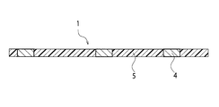
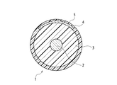
- FIG. 1 is a cross-sectional view of an example of an optical fiber constituting the optical fiber ribbon according to this embodiment.
- the optical fiber 1 constituting the optical fiber ribbon according to the present embodiment is configured by covering a bare optical fiber 2 made of a quartz glass core and cladding with a fiber coating 3. .
- the material of the fiber coating 3 is, for example, an ultraviolet curable resin.
- An optical fiber constituted by the bare optical fiber 2 and the fiber coating 3 is also referred to as an optical fiber.
- the fiber coating 3 may have a multilayer structure in order to constitute a so-called optical fiber core.
- the outer periphery of the ultraviolet curable resin is further coated with a thermoplastic resin, another ultraviolet curable resin, or the like.
- a predetermined marking 4 is provided on the outer peripheral surface of the fiber coating 3 and is further covered with a translucent colored layer 5.
- FIG. 2 is a plan view of an example of an optical fiber constituting the optical fiber ribbon according to the present embodiment.
- the marking 4 is provided for each predetermined distance in the longitudinal direction of the optical fiber.
- the marking 4 is colored with an opaque color such as white having a good light reflectance, and is visible from the outside through the colored layer 5.
- the colored layer 5 is colored in the same color in each optical fiber 1 constituting an optical fiber ribbon to be described later, and the color is changed according to each optical fiber ribbon.
- the marking 4 may be colored with a translucent color. In this case, the marking 4 is darker than the color of the colored layer 5 so as to be visible from the outside through the colored layer 5 ( It is colored dark.
- FIG. 3 is a plan view showing the configuration of the optical fiber ribbon according to this embodiment.
- a plurality of optical fibers 1 are arranged in parallel, and these are covered with a tape forming material 6 to be taped.
- the tape forming material 6 is made of a colorless and transparent material.
- each optical fiber can be identified by the type of marking 4 (for example, the number or color thereof). Moreover, while coloring the colored layer 5 of each optical fiber 1 with the same color and changing the color for every optical fiber tape core wire, it can distinguish from another optical fiber tape core wire.
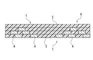
- FIG. 4 is a cross-sectional view of another example of an optical fiber constituting the optical fiber ribbon according to this embodiment.
- the marking 4 may be provided only on a part of the outer peripheral surface of the optical fiber 1.
- the optical fiber ribbon according to the present embodiment has a marking 4 that is different for each optical fiber 1 for each predetermined distance in the longitudinal direction, except for a predetermined one of the plurality of optical fibers 1. And may be configured to be covered with a translucent colored layer 5 of the same color for identifying the optical fiber ribbon. In this case, one predetermined optical fiber 1 may be configured to be covered with a translucent colored layer 5 having a color distinguishable from the color of the colored layer 5 of the other optical fiber 1. This distinguishable color is preferably the same color as the marking 4.
- optical fiber cable configured by covering a plurality of the above-described optical fiber ribbons with a jacket made of a synthetic resin material.
- FIG. 5 is a cross-sectional view showing the configuration of the optical fiber cable according to the present embodiment.
- the optical fiber cable 10 is, for example, a center tube type optical fiber cable.
- the plurality of optical fiber ribbons 11 are gathered in a bundle state to form a cable core.
- the optical fiber cable 10 is formed by extruding a thermoplastic resin 8 into a tube shape on the outer periphery of a plurality of optical fiber ribbons 11 assembled in a bundle, and the outer periphery of the tube is sheathed with a jacket 9 such as polyethylene. It is configured.
- a plurality of optical fiber ribbons 11 except for a predetermined one of the optical fibers 1 constituting the optical fiber ribbon 11 or all of the optical fiber ribbons 11 are optical fibers.
- the optical fiber tape 11 is covered with a translucent colored layer of the same color for identifying the fiber tape core wire 11, and the color of the colored layer is different in different optical fiber tape core wires 11. Identification between the cores 11 is possible.
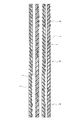
- FIG. 6 is a plan view showing a configuration of an example of the optical fiber ribbon according to the present embodiment.
- an optical fiber ribbon was formed using the optical fiber 1 having an outer diameter of the fiber coating 3 of 250 microns.
- the marking 4 was provided intermittently in the longitudinal direction with a marking length of 2 mm and a marking pitch of 50 mm.
- a colored layer 5 of the same color for identifying the optical fiber ribbon was coated.
- the optical fiber 1 constituting another optical fiber ribbon was coated with another colored layer 5 of the same color.
- each optical fiber 1 was coated with a taped material 6 to form a tape.
- a material for the tape forming material 6 an ultraviolet curable resin was used.
- FIG. 7 is a plan view showing a configuration of a comparative example of the optical fiber ribbon.
- each optical fiber 1 constituting the optical fiber ribbon was coated with a colored layer 5 of a different color.
- FIG. 8 is a plan view showing types of markings in Examples and Comparative Examples.
- the marking 4 is of four types as shown in (a) to (d) of FIG. That is, 4 (1) without marking (a), 1 with 2 mm marking (b), 2 with 2 mm marking (c), and 3 with 2 mm marking (d) It is a kind.
- the state without marking is also considered as a kind of marking.
- optical fiber tape cores of these examples and comparative examples when the discrimination characteristics of the optical fiber tape cores are compared, in the optical fiber tape cores of the examples in which the colored layers 5 of all the optical fibers 1 are the same color Compared to the optical fiber ribbon of the comparative example, it was confirmed that the discrimination of the optical fiber ribbon was significantly improved and the discrimination of the marking 4 was also improved.
- each optical fiber 1 can be seen well even if each optical fiber 1 is separated into single optical fibers.
- the optical fiber 1 divided into single cores could be easily identified by the combination of the marking 4 and the color of the colored layer 5.
- the marking 4 As shown in FIG. 4 described above, even when the marking is provided only on a part of the outer peripheral surface of the optical fiber 1, the marking 4 is extremely distinguishable compared to the optical fiber ribbon of the comparative example. It was confirmed that there was an improvement.
- the colored layer 5 may have various colors such as clear, purple, light blue, white, brown, gray, pink, and orange.
- the color of the predetermined one colored layer 5 of the optical fibers 1 constituting the optical fiber ribbon may be the same as the color of the markings 4 of the other optical fibers 1. In this case, the predetermined one optical fiber is the same as the marking 4 provided on the whole in terms of visibility.
- optical fibers is not limited to four as shown in the embodiment, and may be any number.
- optical fiber cable cores may be used as subunits, and a plurality of optical fiber cable cores may be connected to form a separate type optical fiber cable core.
- the optical fiber cable core wire serving as the subunit has the colored layer 5 of the same color so that each subunit can be identified by the color of the colored layer 5.
- An SZ type optical fiber cable includes a core having a slot groove formed by repeatedly reversing left and right on an outer peripheral surface, an optical fiber tape core housed in the slot groove of the core, a core and an optical fiber tape core Consists of a sheath covering the wire.
- a core in which five slot grooves are formed is used, and five four-core tape core wires are accommodated in each slot groove.
- the optical fiber ribbon the four-fiber ribbons shown in FIGS. 6 and 7 were used.
- the color of the colored layer was different from each other according to the number of each optical fiber ribbon.
- the tracer method is an identification method in which the color of an optical fiber used as a tracer is different from other optical fiber ribbons, and is generally used for identifying optical fiber ribbons.
- the optical fiber used as a tracer is typically a four-fiber optical fiber ribbon in which white, brown, and ash optical fibers are lined up.
- the fiber ribbon is distinguished from blue, yellow, green, red, and purple.
- White, brown, and ash are the same for all optical fiber ribbons, and each optical fiber ribbon is identified only by the tracer color, so check the color of the tracer, not the entire optical fiber ribbon. There is a need. That is, it is necessary to identify one color which is a tracer among the four thin optical fibers arranged side by side.
- the optical fiber according to the present embodiment shown in FIG. When using the fiber tape core wire, the visibility was overwhelmingly better than when using the optical fiber tape core wire in which the color of the colored layer 5 shown in FIG.
- the optical fiber ribbon shown in FIG. 6 has better discrimination.
- the tracer type optical fiber ribbon it is necessary to specify the color of the optical fiber to be a tracer, so it is necessary to check the color of one optical fiber, but the optical fiber tape shown in FIG.
- the identification can be performed in units of the optical fiber tape core wire, and the identification is easier than the tracer type.
- the center tube type optical fiber cable is a cable in which a space for storing an optical fiber ribbon or an interposition member is formed on the central axis of the cable and the periphery is covered with a sheath. With such a cable, several to more than a dozen or more than 20 optical fibers and optical fiber ribbons are stored in the storage space. This embodiment is effective in discriminating an arbitrary optical fiber ribbon from a large number of optical fiber ribbons in such a cable structure.
- the manufactured center tube type optical fiber cable is a 48-core optical fiber cable in which 12 sheets of 4-fiber ribbons are accommodated in a storage space on the central axis.
- the optical fiber ribbon As the optical fiber ribbon, the marking shown in Fig. 6 is provided, and the color of the optical fiber is blue, yellow, green, red, purple, white, brown, ash, peach, water, clear. 12 optical fiber ribbons made of orange were used.
- an optical fiber cable using an optical fiber ribbon manufactured by a tracer method was manufactured, and the discriminability of the optical fiber ribbon was compared.
- 12 tracer colors In the tracer method, in the same way as in the embodiment of the SZ type optical fiber cable, in addition to having to discriminate each tracer color, 12 tracer colors must be used, in order to use a large number of colors.
- optical fiber ribbon is effective when it is desired to easily distinguish a plurality of optical fiber ribbons, such as various wirings, in addition to the optical fiber cable.
- an optical fiber coupler for simultaneously connecting a plurality of optical fiber ribbons was manufactured using the optical fiber ribbon shown in FIG. Also in this case, as in the case of using the optical fiber cable, the optical fiber tape core wire has good discrimination and an improvement in workability is recognized.
- a plurality of such optical fiber couplers are used in closures, optical termination boxes, termination racks, and the like. Even when this optical fiber coupler is housed in a closure using a termination box or a splitter unit, the optical fiber tape core wire has good discrimination and improved workability.
- the optical fiber ribbon, the optical fiber cable, and the wiring form according to the present embodiment it is easy to distinguish between many types of optical fiber ribbons. Further, by changing the color, arrangement, shape, and the like depending on the combination of the colored layer and the marking provided on the optical fiber, it is possible to increase the types and the number of optical fibers while maintaining the distinguishability. Furthermore, since there is a marking under the colored layer, the distinctiveness due to aging is not impaired. Since the marking visibility and discrimination are good, the color of the optical fiber itself (color of the colored layer) can be easily identified. Furthermore, since the marking and the colored layer remain even after the taped material is peeled off, the optical fiber can be easily identified.
- the present invention is applied to an optical fiber ribbon in which a plurality of optical fibers are connected in parallel and an optical fiber cable configured using the optical fiber ribbon.
Landscapes
- Physics & Mathematics (AREA)
- Engineering & Computer Science (AREA)
- Manufacturing & Machinery (AREA)
- General Physics & Mathematics (AREA)
- Optics & Photonics (AREA)
- Optical Fibers, Optical Fiber Cores, And Optical Fiber Bundles (AREA)
Abstract
光ファイバテープ心線であって、並列した複数本の光ファイバ1と、前記複数本の光ファイバ1を被覆してテープ化するテープ化材6とを備え、前記複数本の光ファイバ1は、この光ファイバテープ心線を識別するための同一色の半透明の着色層5で被覆されており、前記テープ化材5は、無色透明な材料により形成されており、前記複数本の光ファイバ1において、所定の1本を除く各光ファイバまたは全ての光ファイバの表面には、その長手方向の所定の距離ごとに、他の光ファイバと異なるマーキング4が設けられている。
Description
本発明は、複数本の光ファイバを並列に連結した光ファイバテープ心線、この光ファイバテープ心線を用いて構成される光ファイバケーブル及び配線形態に関する。
従来、特許文献1に記載されているように、複数本の光ファイバを並列に連結した光ファイバテープ心線が提案されている。このような光ファイバテープ心線は、並列した複数本の光ファイバをテープ化材(被覆材)により被覆して構成されている。この光ファイバは、一般的に、コアとクラッドからなる裸光ファイバの上に紫外線硬化樹脂を被覆することで構成され、光ファイバ素線とも称されている。
このような光ファイバテープ心線において、この光ファイバテープ心線を構成する各光ファイバを識別するには、光ファイバ毎に異なる色に表面を着色することが行われている。また、各光ファイバに異なるマーキングを設けることによっても、光ファイバテープ心線を構成する各光ファイバを識別することができる。
あるいは、各光ファイバを被覆する被覆材の表面に着色、または、マーキングを設けることによっても、各光ファイバを識別することができる。
なお、特許文献2には、光ファイバの表面を透明着色層によって被覆することにより、光ファイバの表面を着色する構成が記載されている。
ところで、前述した従来の光ファイバテープ心線において、光ファイバの表面を着色する場合には、使用できる色の数は限られるため、識別できる光ファイバの本数には限界がある。中間色を用いたとしても、その判別は容易ではなく、識別が困難となってしまう。また、色の組合せにより識別するようにしても、識別は困難である。また、光ファイバの色は、テープ化材を透して識別することになるため、良好な識別性が得られない。
また、光ファイバにマーキングを設ける場合には、光ファイバの色がマーキングに遮られることにより、光ファイバの色による識別性が低下してしまう。
そして、テープ化材の表面にマーキングを設ける場合には、温度、湿度等の影響でマーキングが経年劣化し、識別性が低下してしまう。また、この場合には、テープ化材を剥がし、光ファイバを単体で使用する際には、テープ化材と共にマーキングが無くなってしまう。
さらに、光ファイバテープ心線において、マーキングの位置が長手方向に分散していると、マーキングの組合せを識別することが困難となり、識別性が低下してしまう。
そこで、本発明は、前述の実情に鑑みて提案されるものであって、複数本の光ファイバを並列に連結した光ファイバテープ心線において、多数の種別の光ファイバテープ心線を良好に識別することができ、また、経年劣化による識別性の低下がなく、さらに、テープ化材を剥がして光ファイバを単体で使用する際にも、光ファイバを識別することができるようになされた光ファイバテープ心線、この光ファイバテープ心線を用いて構成される光ファイバケーブル及び配線形態を提供することを目的とする。
本発明の第1の態様は、光ファイバテープ心線であって、並列した複数本の光ファイバと、前記複数本の光ファイバを被覆してテープ化するテープ化材とを備え、前記複数本の光ファイバは、この光ファイバテープ心線を識別するための同一色の半透明の着色層で被覆されており、前記テープ化材は、無色透明な材料により形成されており、前記複数本の光ファイバにおいて、所定の1本を除く各光ファイバまたは全ての光ファイバの表面には、その長手方向の所定の距離ごとに、他の光ファイバと異なるマーキングが設けられていることを要旨とする。
本発明の第2の態様は、光ファイバケーブルであって、複数枚の光ファイバテープ心線を備え、前記各光ファイバテープ心線は、並列した複数本の光ファイバと、前記複数本の光ファイバを被覆してテープ化するテープ化材とを有し、前記複数本の光ファイバは、この光ファイバテープ心線を識別するための同一色の半透明の着色層で被覆されており、前記テープ化材は、無色透明な材料により形成されており、前記複数本の光ファイバにおいて、所定の1本を除く各光ファイバまたは全ての光ファイバの表面には、その長手方向の所定の距離ごとに、他の光ファイバと異なるマーキングが設けられており、前記着色層の色は、前記各光ファイバテープ心線毎に異なる
ことを要旨とする。
ことを要旨とする。
本発明の第3の態様は、複数枚の光ファイバテープ心線の配線形態であって、複数枚の光ファイバテープ心線を備え、前記各光ファイバテープ心線は、並列した複数本の光ファイバと、前記複数本の光ファイバを被覆してテープ化するテープ化材とを有し、前記複数本の光ファイバは、この光ファイバテープ心線を識別するための同一色の半透明の着色層で被覆されており、前記テープ化材は、無色透明な材料により形成されており、前記複数本の光ファイバにおいて、所定の1本を除く各光ファイバまたは全ての光ファイバの表面には、その長手方向の所定の距離ごとに、他の光ファイバと異なるマーキングが設けられており、前記着色層の色は、前記各光ファイバテープ心線毎に異なることを要旨とする。
本発明によれば、光ファイバテープ心線間の識別が容易になる。また、光ファイバに設けた着色層とマーキングとの組合せによる色、配置、形状等を変えることで、識別性を維持しつつ光ファイバの種別や本数を増やすことが可能である。さらに、着色層の下にマーキングがあるので、経年劣化による識別性が損なわれない。マーキングの視認性、判別性が良好であるため、光ファイバ自体の色(着色層の色)の識別が容易である。さらに、テープ化材を剥がしてもマーキング及び着色層が残るため、光ファイバの識別は容易である。
以下、本発明の一実施形態を図面に基づいて説明する。
〔光ファイバテープ心線〕
本実施形態に係る光ファイバテープ心線は、並列した複数本の光ファイバが互いに連結されてテープ化された光ファイバテープ心線である。
本実施形態に係る光ファイバテープ心線は、並列した複数本の光ファイバが互いに連結されてテープ化された光ファイバテープ心線である。
図1は、本実施形態に係る光ファイバテープ心線を構成する光ファイバの一例の断面図である。
本実施形態に係る光ファイバテープ心線を構成する光ファイバ1は、図1に示すように、石英ガラス製のコア及びクラッドからなる裸光ファイバ2がファイバ被覆3によって被覆されて構成されている。ファイバ被覆3の材質は例えば紫外線硬化樹脂である。裸光ファイバ2及びファイバ被覆3によって構成される光ファイバは、光ファイバ素線とも称される。なお、ファイバ被覆3は、所謂光ファイバ心線を構成するために多層構造としてもよい。この場合、上述の紫外線硬化樹脂の外周に更に熱可塑性樹脂や別の紫外線硬化樹脂などを被覆される。そして、ファイバ被覆3の外周面には、所定のマーキング4が設けられ、さらに、半透明の着色層5によって被覆されている。
図2は、本実施形態に係る光ファイバテープ心線を構成する光ファイバの一例の平面図である。
図2に示すように、マーキング4は、光ファイバの長手方向の所定の距離ごとに設けられている。マーキング4は、例えば、光反射率の良い白色等の不透明な色で着色されており、着色層5を透して外部から視認可能となっている。着色層5は、後述する光ファイバテープ心線を構成する各光ファイバ1において、同一の色に着色され、その色が各光ファイバテープ心線に応じて変更される。なお、マーキング4は、半透明な色で着色されてもよいが、その場合、マーキング4は、着色層5を透して外部から視認可能となるように、着色層5の色よりも濃い(暗い)色に着色されている。
図3は、本実施形態に係る光ファイバテープ心線の構成を示す平面図である。
図3に示すように、本実施形態に係る光ファイバテープ心線では、複数本の光ファイバ1が並列し、これらがテープ化材6によって被覆されてテープ化されている。テープ化材6は、無色透明な材料により形成されている。
この光ファイバテープ心線においては、マーキング4の種類(例えば、その個数や色)により、各光ファイバの識別を行うことができる。また、各光ファイバ1の着色層5を同一の色で着色すると共に、その色を光ファイバテープ心線毎に変えることで、他の光ファイバテープ心線との識別を行うことができる。
図4は、本実施形態に係る光ファイバテープ心線を構成する光ファイバの他の例の断面図である。
図4に示すように、マーキング4は光ファイバ1の外周面の一部のみに設けてもよい。
さらに、本実施形態に係る光ファイバテープ心線は、複数本の光ファイバ1のうちの所定の1本を除いて、長手方向の所定の距離ごとに各光ファイバ1ごとに異なるマーキング4を表面に設けるとともに、この光ファイバテープ心線を識別するための同一色の半透明の着色層5で被覆して構成してもよい。この場合、所定の1本の光ファイバ1は、他の光ファイバ1の着色層5の色から区別可能な色による半透明の着色層5で被覆して構成してもよい。この区別可能な色とは、好適には、マーキング4と同一の色である。
〔光ファイバケーブル〕
本実施形態に係る光ファイバケーブルは、複数枚の上述の光ファイバテープ心線を、合成樹脂材料からなる外被によって被覆することで構成される。
本実施形態に係る光ファイバケーブルは、複数枚の上述の光ファイバテープ心線を、合成樹脂材料からなる外被によって被覆することで構成される。
図5は、本実施形態に係る光ファイバケーブルの構成を示す断面図である。
図5に示すように、本実施形態に係る光ファイバケーブル10は、例えば、センターチューブ型の光ファイバケーブルである。複数枚の光ファイバテープ心線11は、バンドル状態に集合され、ケーブルコアを形成している。光ファイバケーブル10は、バンドル状態に集合した複数枚の光ファイバテープ心線11の外周に熱可塑性樹脂8をチューブ状に押出成形し、このチューブの外周をポリエチレンなどの外被9でシースして構成されている。
光ファイバケーブル10においては、複数枚の光ファイバテープ心線11のそれぞれにおいて、光ファイバテープ心線11をなす各光ファイバ1のうちの所定の1本を除いたもの、または、全ては、光ファイバテープ心線11を識別するための同一色の半透明の着色層で被覆されており、異なる光ファイバテープ心線11においては着色層の色が異なり、この着色層の色により、光ファイバテープ心線11間の識別が可能となっている。
〔光ファイバテープ心線の実施例〕
図6は、本実施形態に係る光ファイバテープ心線の実施例の構成を示す平面図である。
図6は、本実施形態に係る光ファイバテープ心線の実施例の構成を示す平面図である。
本実施形態に係る光ファイバテープ心線の実施例として、ファイバ被覆3の外径が250ミクロンである光ファイバ1を用いて、光ファイバテープ心線を構成した。マーキング4は、マーキング長2mm、マーキングピッチ50mmとして、長手方向に間欠的に設けた。マーキング4上には、一の光ファイバテープ心線を構成する光ファイバ1については、この光ファイバテープ心線を識別するための同一色の着色層5を被覆した。他の光ファイバテープ心線を構成する光ファイバ1には、他の同一色の着色層5を被覆した。
この光ファイバ1を4本並ベ、テープ化材6により各光ファイバ1を被覆し、テープ化した。テープ化材6の材料としては、紫外線硬化型樹脂を用いた。
図7は、光ファイバテープ心線の比較例の構成を示す平面図である。
比較例として、実施例と同様の光ファイバを用いて、図7に示すように、光ファイバテープ心線を作製した。この光ファイバテープ心線においては、光ファイバテープ心線を構成する各光ファイバ1は、全て異なる色の着色層5が被覆されたものを用いた。
図8は、実施例及び比較例におけるマーキングの種類を示す平面図である。
これら実施例及び比較例において、マーキング4は、図8中の(a)乃至(d)に示すように、4種類のものとした。すなわち、マーキングのないもの(a)、2mmのマーキングが1つのもの(b)、2mmのマーキングが2つ連続したのもの(c)及び2mmのマーキングが3つ連続したのもの(d)の4種類である。なお、ここでは、マーキングのない状態も、マーキングの一種と考えている。
これら実施例及び比較例の光ファイバテープ心線について、光ファイバテープ心線の識別性を比較すると、全ての光ファイバ1の着色層5が同一色である実施例の光ファイバテープ心線において、比較例の光ファイバテープ心線に比較して、光ファイバテープ心線の識別性が極めて向上し、また、マーキング4の識別性も向上していることが確認された。
また、各光ファイバ1を単心の光ファイバに分離しても、各光ファイバ1に設けたマーキング4は、良好に視認できることを確認した。単心に分けられた光ファイバ1は、マーキング4と着色層5の色との組合せにより、容易に識別が可能であった。
マーキングについては、前述の図4に示すように、光ファイバ1の外周面の一部のみに設けた場合にも、比較例の光ファイバテープ心線に比較して、マーキング4の識別性が極めて向上していることが確認された。
なお、着色層5の色とマーキング4との組合せには種々のものが考えられ、特に限定されるものではない。例えば、着色層5の色は、クリア、紫、水色、白、茶色、灰色、桃色、橙色など、種々のものが考えられる。また、光ファイバテープ心線を構成する光ファイバ1のうちの所定の1本の着色層5の色を、他の光ファイバ1のマーキング4の色と同一の色としてもよい。この場合には、所定の1本の光ファイバは、視認性の点では、全体にマーキング4が設けられたと同様となる。
また、光ファイバの本数は、実施例に示したような4本に限定されるものではなく、どのような本数であってもよい。
さらに、前述した光ファイバケーブル心線をサブユニットとして、この光ファイバケーブル心線を複数連結させて、分離型光ファイバケーブル心線を構成してもよい。この場合には、サブユニットとなる光ファイバケーブル心線ごとに、同一の色の着色層5を有しているようにし、着色層5の色によって、各サブユニットを識別できるようにする。
〔光ファイバケーブルの実施例〕
(1)SZ型光ファイバケーブル
この実施例では、100心のSZ型光ファイバケーブルを作製した。SZ型光ファイバケーブルは、外周面に左右に反転を繰り返し形成されたスロット溝が形成されたコアと、このコアのスロット溝内に収納された光ファイバテープ心線と、コア及び光ファイバテープ心線を被覆するシースから構成される。この実施例では、5本のスロット溝が形成されたコアを用いて、各スロット溝に4心テープ心線を5枚収納して構成した。光ファイバテープ心線は、図6及び図7に示した4心の光ファイバテープ心線を用いた。
(1)SZ型光ファイバケーブル
この実施例では、100心のSZ型光ファイバケーブルを作製した。SZ型光ファイバケーブルは、外周面に左右に反転を繰り返し形成されたスロット溝が形成されたコアと、このコアのスロット溝内に収納された光ファイバテープ心線と、コア及び光ファイバテープ心線を被覆するシースから構成される。この実施例では、5本のスロット溝が形成されたコアを用いて、各スロット溝に4心テープ心線を5枚収納して構成した。光ファイバテープ心線は、図6及び図7に示した4心の光ファイバテープ心線を用いた。
各光ファイバテープ心線において、着色層の色は、各光ファイバテープ心線の番号に応じて互いに異なるものとした。
これらの光ファイバケーブルを用いて、識別性の比較を行った。スロット溝から取り出した5枚の光ファイバテープ心線について、各番号に対応した識別性を確認した。識別性の比較に際しては、実施例の光ファイバケーブルと併せて、比較のために、従来から使用されている光ファイバテープ心線の識別方式であるトレーサー方式による光ファイバテープ心線を用いて光ファイバケーブルについても確認した。
なお、トレーサー方式は、トレーサーとして用いる光ファイバの色を他の光ファイバテープ心線と異ならせることによる識別方法で、光ファイバテープ心線の識別に一般的に使用されている。例えば、トレーサーとして用いる光ファイバと、白、茶、灰の光ファイバとを並べた4心の光ファイバテープ心線とするのが典型的なもので、トレーサー色を、1番~5番の光ファイバテープ心線で、青、黄、緑、赤、紫と異ならせて識別する。白、茶、灰は、全ての光ファイバテープ心線で同一であり、トレーサー色のみで各光ファイバテープ心線の識別を行うため、光ファイバテープ心線全体ではなく、トレーサーの色を確認する必要がある。すなわち、4本並んでいる細い光ファイバのうちのトレーサーである1本の色を識別する必要がある。
図6に示した光ファイバテープ心線を用いた光ファイバケーブルと、図7に示した光ファイバテープ心線を用いた光ファイバケーブルとの比較においては、図6に示す本実施形態に係る光ファイバテープ心線を用いた場合が、図7に示す着色層5の色が光ファイバ1ごとに異なる光ファイバテープ心線を用いた場合に対して、圧倒的に視認性が良好であった。
トレーサーとしての光ファイバを有する従来の光ファイバテープ心線との比較においても、図6に示す光ファイバテープ心線を用いた場合のほうが、良好な識別性を有することが確認された。トレーサー型の光ファイバテープ心線では、トレーサーとなる光ファイバの色を特定する必要があるため、1本の光ファイバの色を注視して確認する必要があるが、図6に示す光ファイバテープ心線を用いた場合では、前述したように、光ファイバテープ心線線単位での識別が可能であり、トレーサー型に比較して識別が容易であった。
(2)センターチューブ型光ファイバケーブル
この実施例では、センターチューブ型光ファイバケーブルを作製した。
この実施例では、センターチューブ型光ファイバケーブルを作製した。
センターチューブ型光ファイバケーブルは、ケーブルの中央軸上に光ファイバテープ心線や介在部材等を収納する空間が形成され、周囲をシースにより被覆したケーブルである。このようなケーブルでは、収納空間に数本乃至十数本、あるいは、20本を超える光ファイバや光ファイバテープ心線が収納される。本実施形態は、このようなケーブル構造において、多数の光ファイバテープ心線から任意の光ファイバテープ心線を識別するのに有効である。
作製したセンターチューブ型光ファイバケーブルは、中央軸上の収納空間内に4心の光ファイバテープ心線を12枚収納した48心の光ファイバケーブルである。光ファイバテープ心線として、図6に示したマーキングを設け、光ファイバの色を各々の光ファイバテープ心線で青、黄、緑、赤、紫、白、茶、灰、桃、水、クリア、橙とした12枚の光ファイバテープ心線を用いた。比較のために、トレーサー方式で作製した光ファイバテープ心線を用いた光ファイバケーブルを作製し、光ファイバテープ心線の識別性を比較した。トレーサー方式では、SZ型光ファイバケーブルの実施例と同様に、トレーサー色を各々判別しなければならないことに加え、12色のトレーサー色を使用しなければならず、多数の色を使用するために、例えば、同系色である赤と桃色や、赤と橙などの識別が難しい。これに対し、本発明に係る光ファイバテープ心線を用いた場合には、複数本の同一色の光ファイバ1が並んでいることにより、同系色でも判別が容易であり、光ファイバテープ心線の識別性が良好であった。
(3)光ファイバカプラへの適用
本実施形態に係る光ファイバテープ心線は、光ファイバケーブル以外にも、各種配線など、複数の光ファイバテープ心線を容易に判別したい場合に有効である。
本実施形態に係る光ファイバテープ心線は、光ファイバケーブル以外にも、各種配線など、複数の光ファイバテープ心線を容易に判別したい場合に有効である。
実施例として、複数の光ファイバテープ心線を同時に接続させる光ファイバカプラを、図6に示した光ファイバテープ心線を用いて作製した。この場合にも、光ファイバケーブルに用いた場合と同様に、光ファイバテープ心線の識別性が良好であり、作業性の向上が認められた。このような光ファイバカプラは、クロージャや光成端箱、成端架等において複数個使用される。この光ファイバカプラを、成端箱やスプリッタユニットを用いてクロージャに収納した場合にも、光ファイバテープ心線の識別性が良好であり、作業性の向上が認められた。
本実施形態に係る光ファイバテープ心線、光ファイバケーブル及び配線形態によれば、多数の種別の光ファイバテープ心線間の識別が容易になる。また、光ファイバに設けた着色層とマーキングとの組合せによる色、配置、形状等を変えることで、識別性を維持しつつ光ファイバの種別や本数を増やすことが可能である。さらに、着色層の下にマーキングがあるので、経年劣化による識別性が損なわれない。マーキングの視認性、判別性が良好であるため、光ファイバ自体の色(着色層の色)の識別が容易である。さらに、テープ化材を剥がしてもマーキング及び着色層が残るため、光ファイバの識別は容易である。
本発明は、複数本の光ファイバを並列に連結した光ファイバテープ心線及びこの光ファイバテープ心線を用いて構成される光ファイバケーブルに適用される。
Claims (3)
- 光ファイバテープ心線であって、
並列した複数本の光ファイバと、
前記複数本の光ファイバを被覆してテープ化するテープ化材と
を備え、
前記複数本の光ファイバは、この光ファイバテープ心線を識別するための同一色の半透明の着色層で被覆されており、
前記テープ化材は、無色透明な材料により形成されており、
前記複数本の光ファイバにおいて、所定の1本を除く各光ファイバまたは全ての光ファイバの表面には、その長手方向の所定の距離ごとに、他の光ファイバと異なるマーキングが設けられている
ことを特徴とする。 - 光ファイバケーブルであって、
複数枚の光ファイバテープ心線を備え、
前記各光ファイバテープ心線は、
並列した複数本の光ファイバと、
前記複数本の光ファイバを被覆してテープ化するテープ化材と
を有し、
前記複数本の光ファイバは、この光ファイバテープ心線を識別するための同一色の半透明の着色層で被覆されており、
前記テープ化材は、無色透明な材料により形成されており、
前記複数本の光ファイバにおいて、所定の1本を除く各光ファイバまたは全ての光ファイバの表面には、その長手方向の所定の距離ごとに、他の光ファイバと異なるマーキングが設けられており、
前記着色層の色は、前記各光ファイバテープ心線毎に異なる
ことを特徴とする。
- 複数枚の光ファイバテープ心線の配線形態であって、
複数枚の光ファイバテープ心線を備え、
前記各光ファイバテープ心線は、
並列した複数本の光ファイバと、
前記複数本の光ファイバを被覆してテープ化するテープ化材と
を有し、
前記複数本の光ファイバは、この光ファイバテープ心線を識別するための同一色の半透明の着色層で被覆されており、
前記テープ化材は、無色透明な材料により形成されており、
前記複数本の光ファイバにおいて、所定の1本を除く各光ファイバまたは全ての光ファイバの表面には、その長手方向の所定の距離ごとに、他の光ファイバと異なるマーキングが設けられており、
前記着色層の色は、前記各光ファイバテープ心線毎に異なる
ことを特徴とする。
Applications Claiming Priority (2)
| Application Number | Priority Date | Filing Date | Title |
|---|---|---|---|
| JP2010097118A JP2011227298A (ja) | 2010-04-20 | 2010-04-20 | 光ファイバテープ心線、光ファイバケーブル及び配線形態 |
| JP2010-097118 | 2010-04-20 |
Publications (1)
| Publication Number | Publication Date |
|---|---|
| WO2011132610A1 true WO2011132610A1 (ja) | 2011-10-27 |
Family
ID=44834130
Family Applications (1)
| Application Number | Title | Priority Date | Filing Date |
|---|---|---|---|
| PCT/JP2011/059389 Ceased WO2011132610A1 (ja) | 2010-04-20 | 2011-04-15 | 光ファイバテープ心線、光ファイバケーブル及び配線形態 |
Country Status (3)
| Country | Link |
|---|---|
| JP (1) | JP2011227298A (ja) |
| TW (1) | TW201207458A (ja) |
| WO (1) | WO2011132610A1 (ja) |
Cited By (4)
| Publication number | Priority date | Publication date | Assignee | Title |
|---|---|---|---|---|
| CN107346046A (zh) * | 2017-06-30 | 2017-11-14 | 南京吉隆光纤通信股份有限公司 | 具有侧面识别标记的非圆对称光纤 |
| CN107533204A (zh) * | 2015-06-22 | 2018-01-02 | 株式会社藤仓 | 光纤带、光缆以及光纤芯线 |
| US10185110B2 (en) | 2014-11-20 | 2019-01-22 | Fujikura Ltd. | Optical fiber ribbon, optical fiber cable, and method for producing optical fiber ribbon |
| JPWO2021049626A1 (ja) * | 2019-09-11 | 2021-03-18 |
Families Citing this family (3)
| Publication number | Priority date | Publication date | Assignee | Title |
|---|---|---|---|---|
| JP6248798B2 (ja) * | 2014-05-16 | 2017-12-20 | 住友電気工業株式会社 | テープ心線、および光ケーブル |
| CN112601997B (zh) * | 2018-08-27 | 2023-01-10 | 住友电气工业株式会社 | 带有识别标记的光纤芯线、带有识别标记的光纤芯线的制造方法 |
| JP7552621B2 (ja) * | 2020-02-03 | 2024-09-18 | 住友電気工業株式会社 | 光ファイバケーブル |
Citations (2)
| Publication number | Priority date | Publication date | Assignee | Title |
|---|---|---|---|---|
| JP2005326781A (ja) * | 2004-05-17 | 2005-11-24 | Fujikura Ltd | 光ファイバ心線及び光ファイバケーブル |
| JP2005331823A (ja) * | 2004-05-21 | 2005-12-02 | Fujikura Ltd | 光ファイバ着色心線、光ファイバ着色テープ心線、光ファイバケーブル、及び光ファイバドロップケーブル |
-
2010
- 2010-04-20 JP JP2010097118A patent/JP2011227298A/ja active Pending
-
2011
- 2011-04-15 WO PCT/JP2011/059389 patent/WO2011132610A1/ja not_active Ceased
- 2011-04-20 TW TW100113725A patent/TW201207458A/zh unknown
Patent Citations (2)
| Publication number | Priority date | Publication date | Assignee | Title |
|---|---|---|---|---|
| JP2005326781A (ja) * | 2004-05-17 | 2005-11-24 | Fujikura Ltd | 光ファイバ心線及び光ファイバケーブル |
| JP2005331823A (ja) * | 2004-05-21 | 2005-12-02 | Fujikura Ltd | 光ファイバ着色心線、光ファイバ着色テープ心線、光ファイバケーブル、及び光ファイバドロップケーブル |
Cited By (7)
| Publication number | Priority date | Publication date | Assignee | Title |
|---|---|---|---|---|
| US10185110B2 (en) | 2014-11-20 | 2019-01-22 | Fujikura Ltd. | Optical fiber ribbon, optical fiber cable, and method for producing optical fiber ribbon |
| CN107533204A (zh) * | 2015-06-22 | 2018-01-02 | 株式会社藤仓 | 光纤带、光缆以及光纤芯线 |
| EP3312649A4 (en) * | 2015-06-22 | 2019-03-06 | Fujikura Ltd. | GLASS FIBER BAND, FIBER CABLE AND FIBERGLASS WIRE |
| US10393983B2 (en) | 2015-06-22 | 2019-08-27 | Fujikura Ltd. | Optical fiber ribbon, optical fiber cable, and optical fiber |
| CN107533204B (zh) * | 2015-06-22 | 2019-11-01 | 株式会社藤仓 | 光纤带、光缆以及光纤芯线 |
| CN107346046A (zh) * | 2017-06-30 | 2017-11-14 | 南京吉隆光纤通信股份有限公司 | 具有侧面识别标记的非圆对称光纤 |
| JPWO2021049626A1 (ja) * | 2019-09-11 | 2021-03-18 |
Also Published As
| Publication number | Publication date |
|---|---|
| JP2011227298A (ja) | 2011-11-10 |
| TW201207458A (en) | 2012-02-16 |
Similar Documents
| Publication | Publication Date | Title |
|---|---|---|
| JP5227996B2 (ja) | 光ファイバテープ心線、光ファイバケーブル及び配線形態 | |
| WO2011132610A1 (ja) | 光ファイバテープ心線、光ファイバケーブル及び配線形態 | |
| JP5238620B2 (ja) | 光ファイバケーブル及びその心線識別方法 | |
| JP6248798B2 (ja) | テープ心線、および光ケーブル | |
| US8290321B2 (en) | Cable with features for distinguishing between fiber groups | |
| JP5901933B2 (ja) | 光ファイバテープ心線、光ファイバコア、光ファイバケーブル及び光ファイバケーブルの中間後分岐方法 | |
| JP2013097350A (ja) | 光ファイバユニット及び光ファイバケーブル | |
| JP5870002B2 (ja) | 光ファイバケーブル | |
| JP4972177B2 (ja) | 多心テープ心線及び光ケーブル | |
| JP6315029B2 (ja) | 光ケーブルの製造方法 | |
| JP7552621B2 (ja) | 光ファイバケーブル | |
| JP3927051B2 (ja) | 光ファイバテープ心線の集合体 | |
| US9195018B2 (en) | Cable with features for distinguishing between fiber groups | |
| JP2013109173A (ja) | 光ファイバテープ心線 | |
| JPH0943465A (ja) | テープ状光ファイバ心線 | |
| JP4304106B2 (ja) | 光ドロップケーブル | |
| JP2011257482A (ja) | 光ファイバテープ心線、光ファイバテープ心線の製造方法及び光ファイバケーブル | |
| JP2005283765A (ja) | 光ドロップケーブル | |
| JP2005283764A (ja) | 光ドロップケーブル | |
| JPWO2019172214A1 (ja) | 光ファイバテープ心線、光ユニット、光ファイバケーブル | |
| JP2007232917A (ja) | 光ファイバテープ心線 | |
| JP2006003689A (ja) | 光ドロップケーブル | |
| JP2007264193A (ja) | 光ファイバケーブル | |
| JP2013221966A (ja) | 光ファイバテープ心線および光ファイバケーブル |
Legal Events
| Date | Code | Title | Description |
|---|---|---|---|
| 121 | Ep: the epo has been informed by wipo that ep was designated in this application |
Ref document number: 11771945 Country of ref document: EP Kind code of ref document: A1 |
|
| NENP | Non-entry into the national phase |
Ref country code: DE |
|
| 122 | Ep: pct application non-entry in european phase |
Ref document number: 11771945 Country of ref document: EP Kind code of ref document: A1 |