WO2011132580A1 - 減速装置 - Google Patents
減速装置 Download PDFInfo
- Publication number
- WO2011132580A1 WO2011132580A1 PCT/JP2011/059155 JP2011059155W WO2011132580A1 WO 2011132580 A1 WO2011132580 A1 WO 2011132580A1 JP 2011059155 W JP2011059155 W JP 2011059155W WO 2011132580 A1 WO2011132580 A1 WO 2011132580A1
- Authority
- WO
- WIPO (PCT)
- Prior art keywords
- cage
- internal gear
- roller
- speed reducer
- Prior art date
Links
Images


Classifications
-
- F—MECHANICAL ENGINEERING; LIGHTING; HEATING; WEAPONS; BLASTING
- F16—ENGINEERING ELEMENTS AND UNITS; GENERAL MEASURES FOR PRODUCING AND MAINTAINING EFFECTIVE FUNCTIONING OF MACHINES OR INSTALLATIONS; THERMAL INSULATION IN GENERAL
- F16H—GEARING
- F16H1/00—Toothed gearings for conveying rotary motion
- F16H1/28—Toothed gearings for conveying rotary motion with gears having orbital motion
- F16H1/32—Toothed gearings for conveying rotary motion with gears having orbital motion in which the central axis of the gearing lies inside the periphery of an orbital gear
-
- F—MECHANICAL ENGINEERING; LIGHTING; HEATING; WEAPONS; BLASTING
- F16—ENGINEERING ELEMENTS AND UNITS; GENERAL MEASURES FOR PRODUCING AND MAINTAINING EFFECTIVE FUNCTIONING OF MACHINES OR INSTALLATIONS; THERMAL INSULATION IN GENERAL
- F16H—GEARING
- F16H25/00—Gearings comprising primarily only cams, cam-followers and screw-and-nut mechanisms
- F16H25/04—Gearings comprising primarily only cams, cam-followers and screw-and-nut mechanisms for conveying rotary motion
- F16H25/06—Gearings comprising primarily only cams, cam-followers and screw-and-nut mechanisms for conveying rotary motion with intermediate members guided along tracks on both rotary members
-
- F—MECHANICAL ENGINEERING; LIGHTING; HEATING; WEAPONS; BLASTING
- F16—ENGINEERING ELEMENTS AND UNITS; GENERAL MEASURES FOR PRODUCING AND MAINTAINING EFFECTIVE FUNCTIONING OF MACHINES OR INSTALLATIONS; THERMAL INSULATION IN GENERAL
- F16H—GEARING
- F16H1/00—Toothed gearings for conveying rotary motion
- F16H1/28—Toothed gearings for conveying rotary motion with gears having orbital motion
- F16H1/32—Toothed gearings for conveying rotary motion with gears having orbital motion in which the central axis of the gearing lies inside the periphery of an orbital gear
- F16H2001/323—Toothed gearings for conveying rotary motion with gears having orbital motion in which the central axis of the gearing lies inside the periphery of an orbital gear comprising eccentric crankshafts driving or driven by a gearing
Definitions
- the present invention relates to a roller-type speed reducer that sequentially engages an inner tooth formed on the inner periphery of an internal gear with a smaller number of rollers than the inner tooth to decelerate and transmit the rotation of the input shaft to the output shaft.
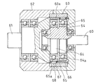
- FIG. 21 and FIG. 22 show the roller type speed reducer described in Patent Document 1.
- FIG. in this roller-type speed reducer the input shaft 60 and the output shaft 61 are arranged coaxially so that the shaft end portions face each other, and a plurality of curved inner teeth 63a are internally formed by a housing 62 that covers the shaft end portions of both shafts.
- Two eccentric discs 64 that support the inner gear 63 on the periphery and are rotatable in the inner gear 63 are provided at the axial end of the input shaft 60 at intervals in the axial direction.
- a cage 66 disposed between the inner gear 63 and the bearing 65 press-fitted into the outer diameter surface of the eccentric disk 64 is provided at the shaft end, and the cage 66 is opposed to each of the two eccentric disks 64.
- a plurality of pockets 67 having a smaller number than the inner teeth 63a are formed at equal intervals in the circumferential direction, and a roller 68 capable of rolling along the outer diameter surface of the bearing 65 is accommodated in each of the pockets 67. is doing.
- the roller 68 when the input shaft 60 rotates, the roller 68 sequentially meshes with the internal teeth 63a of the internal gear 63 due to the rotation of the eccentric disk 64, and per rotation of the input shaft 60, The position of the roller 68 is shifted in the circumferential direction by one tooth of the inner teeth 63a, and the output shaft 61 rotates at a reduced speed with respect to the input shaft 60.
- the tooth profile of the internal teeth 63a is set so that all of the plurality of rollers 68 are in contact with the internal teeth 63a.
- the output shaft 61 is rotated by the rotation of the eccentric disk 64.
- a curve outside the roller 68 among the curves parallel to the locus drawn by the center of the roller 68 is defined as one tooth. Tooth shape to be.
- roller type speed reducer as described above, if the contact pressure between the contact portion between the roller 68 and the inner teeth 63a and the contact portion between the roller 68 and the outer ring surface 65a of the bearing 65 increases, the roller contact portion is likely to be damaged.
- the reduction gear has a short life. Therefore, in order to extend the life of the reduction gear, it is necessary to reduce the surface pressure at the roller contact portion.
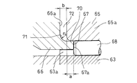
- the axial length of the pocket 67 needs to be increased according to the axial length of the roller 68.
- the pocket 67 is formed by punching by forging or pressing.
- a indicates the width dimension of the flat portion 70.
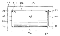
- arc surfaces 67c are formed at the four corners of the pocket 67 for accommodating the roller 68 so as to relieve stress.
- the radius of curvature r 5 of 67c is larger than the radius of curvature r 1 of the arc-shaped chamfer 68c formed at the intersection of the rolling surface 68a and the end face 68b of the roller 68, the interference the chamfer 68c is in the pocket 4 corners of the arcuate surface 67c since that will, and to reduce the radius of curvature r 5 in the arcuate surface 67c than the radius of curvature r 1 of the chamfer 68c of the roller 68, it is impossible to ensure a large arcuate surface 67c of the curvature radius. As a result, a sufficient stress relaxation effect cannot be obtained, and there are still points to be improved in enhancing the durability of the cage 66.
- an eccentric disk 64 shown in FIG. 21 is provided integrally with the input shaft 60, and the outer diameter surface of the eccentric disk 64 is a press-fit surface 64 a of the bearing 65. Therefore, post-processing of the press-fitting surface 64a is necessary, and the press-fitting surface 64a is eccentric with respect to the input shaft 60, so that there is a problem that grinding is difficult and the processing cost is increased.
- the first object of the present invention is to improve the life of the cage by increasing the roller length without increasing the axial length of the cage.
- the second object of the present invention is to reduce the processing cost of the roller type reduction gear.
- a fixed housing an internal gear supported by the housing and provided with a plurality of internal teeth on its inner periphery
- An input shaft having an eccentric disk rotatable in a gear at the shaft end, and an output shaft arranged coaxially with the input shaft, and at the shaft end of the output shaft facing the input shaft
- a cage that is rotatable between the internal gear and the eccentric disc is provided, and the number of teeth of the internal teeth formed on the inner periphery of the internal gear is different from the eccentric disc of the cage in the radial direction.
- a plurality of pockets are provided at equal intervals in the circumferential direction, and a roller that meshes with the inner teeth is accommodated in each of the pockets, and the rollers are sequentially meshed with the inner teeth by the rotation of the eccentric disk, and the input shaft By moving one inner tooth in the circumferential direction per rotation
- the deceleration device which is adapted to decelerate the rotation force shaft is to that employed a configuration in which a recess of annular cross-section of the closed end surface and the inner surface of the cage.
- a predetermined die for securing the strength of the pocket punching die from the end surface on the back side of the pocket to the closed end surface side of the cage.
- a cylindrical flat portion having a width dimension can be secured, and the axial length of the pocket can be increased without increasing the axial length of the cage.
- the axial length of the roller can be increased by increasing the axial length of the pocket, the surface pressure of the roller contact portion can be reduced, and the life of the reduction gear can be extended. Can do.
- the concave portion may be formed by cutting, but if it is formed by forging, the processing is easy and the cost can be reduced.
- the roller is partially covered on the inner circumferential circle of the internal gear when a deviation occurs in the coaxiality of the internal gear and the housing. Phenomenon such as strong contact with teeth occurs, the surface pressure of the portion becomes excessive, resulting in a short life, and problems such as uneven rotation occur.
- the above-mentioned problems can be solved by supporting the inner gear on the inner surface of the housing so as to be alignable.
- the internal gear is spline fitted to the inner surface of the housing, an elastic member is provided between the fitting surfaces of the spline, and the elastic deformation of the elastic member causes the housing and the internal gear to A structure that absorbs the deviation of the coaxiality and a plurality of bolt insertion holes that penetrate from one end surface to the other end surface are formed in the internal gear, and are inserted into the bolt insertion holes and screwed into screw holes formed in the end surface of the housing. It is possible to adopt a configuration in which an internal gear is supported by a bolt, an elastic member is incorporated between the bolt and the bolt insertion hole, and a deviation in coaxiality between the housing and the internal gear is absorbed by elastic deformation of the elastic member.
- the surface roughness of the internal teeth is Ra 1.6 or less, an effect can be obtained in preventing wear of the internal teeth.
- At least one of the pair of end faces facing each other in the cage axial direction of the pocket is formed at the intersection of the roller rolling face and the end face.
- the curved end surface smoothly continues to the side surface opposed in the circumferential direction of the cage, and is directed toward the curved end surface of the roller accommodated in the pocket.
- the structure which provided the control means which controls a movement is employ
- each end surface of the pocket in the cage axial direction is a curved surface, while at least a plurality of pockets in the pocket row located on the open end side of the cage are curved on at least the end surfaces located on the cage closed end side.
- the following means (a) to (c) can be adopted as the restricting means for restricting the movement of the roller toward the curved end face.
- a stopper member is incorporated in the curved surface of the pocket, and the movement of the roller toward the curved end surface is regulated by the stopper.
- the small diameter cylindrical surface has an axial width that forms a shoulder at the continuous portion of the side surface and the curved end surface facing each other in the cage circumferential direction. Since the press-fitting position of the fixing ring can be regulated, the fixing ring can be easily attached.
- the stopper member may be made of a bent product of a metal plate piece, or may be made of a synthetic resin molded product or a rubber molded product. .
- the eccentric disk is separated from the input shaft, and the eccentric disk is fitted to the input shaft. Therefore, a configuration that prevents rotation was adopted.
- the detent of the eccentric disk with respect to the input shaft may be by press fitting, or may be by fitting of a spline or serration.
- a method of forming an eccentric disk shape by forging or pressing and forming an outer diameter surface of the eccentric disk shape by grinding when forming the eccentric disk If it employ
- the annular recess is formed at the intersection of the inner diameter surface of the cage and the closed end surface, so that the axial length of the pocket can be increased without enlarging the axial length of the cage. Since the enlargement can be achieved, the roller can be lengthened, and the service life can be extended by reducing the surface pressure at the roller contact portion.
- the end surface of the pocket at least on the closed side of the cage is curved, and both ends of the curved end surface are smoothly connected to the side surfaces facing the pocket in the circumferential direction of the pocket, thereby rotating the input shaft.
- the eccentric disk is separated from the input shaft, the outer diameter surface of the eccentric disk can be easily finished by centerless grinding or the like, and the processing cost is reduced. be able to.
- FIG. 17 is an exploded perspective view showing the input shaft, the eccentric disc, and the spacer of the reduction gear shown in FIG.
- FIG. 19 is an exploded perspective view showing the input shaft, the eccentric disc, and the spacer of the reduction gear shown in FIG. Longitudinal front view showing a conventional speed reducer Sectional drawing which expands and shows a part of speed reducer shown in FIG. Plan view showing a conventional pocket example
- FIG. 1 to 3 show a first embodiment of a reduction gear device according to the present invention.
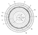
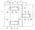
- the housing 1 has a cylindrical shape.
- the housing 1 is divided into two in the axial direction, and a first divided housing 1a and a second divided housing 1b are provided.
- the first divided housing 1a and the second divided housing 1b are coupled and integrated by tightening bolts (not shown), and the inner surface of the abutting side end spans the first divided housing 1a and the second divided housing 1b.
- a large-diameter recess 2 is formed.
- An internal gear 3 is press-fitted into the large-diameter recess 2, and a plurality of internal teeth 4 are provided on the inner periphery of the internal gear 3.
- the end plate 5 is provided at the opening end of the first divided housing 1a, and the input shaft 7 is inserted into the shaft insertion hole 6 formed in the center of the end plate 5.
- the input shaft 7 is rotatably supported by a bearing 8 incorporated in the shaft insertion hole 6, is arranged coaxially with the internal gear 3, and has an internal gear 3 at the end of the shaft located in the housing 1b.
- Two eccentric discs 9 which can be rotated inside are provided at intervals in the axial direction.
- the center O 1 of the cylindrical outer diameter surface 9 a is eccentric with respect to the axis O 0 of the input shaft 7.
- ⁇ shown in FIG. 2 indicates the amount of eccentricity.
- the two eccentric discs 9 are shifted from the center O 1 of the cylindrical outer diameter surface 9a by 180 ° in the circumferential direction.
- a bearing 10 is attached to each of the outer diameter surfaces 9 a of the two eccentric disks 9.
- An output shaft 11 is inserted inside the second divided housing 1b, and the output shaft 11 is rotatably supported by a bearing 12 incorporated in the open end of the second divided housing 1b, and is coaxial with the input shaft 7. It is supposed to be arranged.
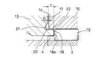
- a cage 13 is provided at the end of the output shaft 11 facing the input shaft 7, and the cage 13 is disposed between the bearing 10 on the eccentric disc 9 and the facing portion of the internal gear 3.
- the cage 13 has a closed end, and a bearing 16 for receiving the shaft end portion of the input shaft 7 is incorporated in a small-diameter hole portion 15 formed in the central portion of the closed end surface 14.
- a minute gap 17 is formed between the closed end surface 14 and the side surface of the bearing 10 facing the closed end surface 14. 3 indicates the size of the gap 17.
- a plurality of pockets 18 arranged in the circumferential direction at equal intervals are formed in the cage 13 in a double row, and the pockets 18 in each row are opposed to the bearings 10 attached to the two eccentric disks 9 respectively.
- the pockets 18 in one row and the pockets 18 in the other row are offset by a half pitch in the circumferential direction.
- the number of the plurality of pockets 18 arranged at equal intervals in the circumferential direction is different from the number of teeth of the internal teeth 4 of the internal gear 3.
- the number of pockets 18 is smaller than the number of teeth of the inner teeth 4, but conversely, the number of pockets 18 may be larger than the number of teeth of the inner teeth 4.
- a roller 19 is accommodated in each of the double-row pockets 18 so as to be movable in the radial direction.
- the roller 19 can be meshed with the internal teeth 4 of the internal gear 3, and the internal teeth 4 with which the rollers 19 are meshed have a rotation angle of the output shaft 11 as described in Patent Document 1 described above.
- a tooth profile having one tooth corresponding to a curve outside the roller 19 among the curves parallel to the locus drawn by the center of the roller 19 is used.
- the cage 13 is formed with an annular recess 21 at the intersection of the inner diameter surface 20 and the closed end surface 14.
- the concave portion 21 is formed by forging, but may be formed by cutting.
- the reduction gear shown in the first embodiment has the above-described structure.
- the roller 19 sequentially meshes with the internal teeth 4 of the internal gear 3 by the rotation of the eccentric disk 9, and the input shaft 7, the roller 19 moves in the circumferential direction by one tooth of the inner teeth 4, and the output shaft 11 rotates at a reduced speed with respect to the input shaft 7.
- the pocket 18 provided on the closed end side of the cage 13
- a cylindrical flat portion 22 having a predetermined width dimension for securing the strength of the pocket punching die can be secured from the end surface 18 a on the back side of the pocket 18 to the closed end surface 14 side of the cage 13.
- the axial length of the pocket 18 without increasing the axial length of the cage 13. Since the axial length of the roller 19 can be increased by increasing the axial length of the pocket 18, the surface pressure of the contact portion of the roller 18 can be reduced, and the life of the reduction gear can be extended. Can be achieved. 3 indicates the axial length of the flat portion 22.
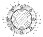
- the fitting of the large-diameter recess 2 formed in the housing 1 and the internal gear 3 is performed outside the internal gear 3.
- the spline 23 is fitted by fitting the axial tooth 24 formed on the radial surface and the axial groove 25 formed on the inner diameter surface of the large-diameter recess 2, and the elastic member 26 is interposed between the fitting surfaces by the spline 23.
- the fitting of the large-diameter recess 2 and the internal gear 3 is the fitting of the spline 23, and the elastic member 26 is provided between the fitting surfaces of the spline 23. Since the shift of the coaxiality between 1 and the internal gear 3 can be absorbed, damage to some of the internal teeth 4 can be prevented, and rotation unevenness can be prevented.
- a large-diameter recess 33 is formed at the end of the housing body 31, and the internal gear 3 is incorporated in the large-diameter recess 33.
- a plurality of axial holes 34 are formed in the outer peripheral portion of the end plate 32 at intervals in the circumferential direction, and the bolts 35 inserted into the axial holes 34 are axial bolt insertion holes provided in the internal gear 3.
- the small-diameter screw shaft 35a formed at the tip of the bolt 35 is threadedly engaged with the screw hole 37 formed in the closed end surface of the large-diameter recess 33, and the internal gear 3 is fastened to the bolt 35 by tightening.
- a cylindrical elastic member 38 is incorporated between the bolt 35 and the bolt insertion hole 36.
- the elastic member 38 elastically deforms the housing 1 and the internal gear 3 in the same manner as the reduction gear shown in the second embodiment. Since the deviation of the coaxiality can be absorbed, it is possible to prevent some of the internal teeth 4 from being damaged and to prevent the occurrence of rotation unevenness.
- the roller 19 has the inner teeth 4 at the time of rotation transmission in which the rotation of the input shaft 7 is decelerated and transmitted to the output shaft 11. Since the inner teeth 4 move to the adjacent inner teeth 4 while maintaining a state in contact with the surface, the inner teeth 4 are likely to be worn when the surface roughness of the inner teeth 4 is large.
- the wear amount of the inner teeth 4 is greatly reduced by setting the surface roughness of the inner teeth 4 to Ra 1.6 or less. Then, the surface roughness of the inner teeth 4 is set to Ra 1.6 or less to improve wear resistance.
- the input shaft 7 is provided with two eccentric discs 9, but the number of the eccentric discs 9 is not limited to two.
- one eccentric disk 9 may be provided on the input shaft 7.
- the concentrated stress acting on the four corners of the pocket 18 of the pocket row located on the open end side of the cage 13 is large at the corner portion on the closed end side of the cage 13 and small at the corner portion on the open end side of the cage 13. Is shown. Therefore, in the cage 13 having the double row pocket row, the cage closure of the pocket 18 of the pocket row located on the four corners of the pocket 18 located on the closed end side of the cage 13 and the open end side of the cage 13 is performed. The durability of the cage 13 can be greatly improved by relaxing the stress at the two corners on the end side.
- each of the pockets 18 in the pocket row located on the closed end side of the cage 13 has a cage axial direction.
- Each of the pair of end surfaces 18b facing each other is formed into a curved surface having a radius of curvature larger than the radius of curvature of the arc-shaped chamfer 19c formed at the intersection of the rolling surface 19a and the end surface 19b of the roller 19.
- each of the end surfaces 18 b located on the closed end side of the cage 13 has a curved surface shape with a larger radius of curvature than the chamfer 19 c of the roller 19.
- each of the end surfaces 18b located on the opening end side of the cage 13 is a flat surface, and an arc surface 18c is provided at the intersection of the end surface 18b and the side surface 18a, and the radius of curvature r 2 of the arc surface 18c. It is smaller than the radius of curvature r 1 of the arc-shaped chamfer 19c of the roller 19 (see FIG. 11).
- the curved end face 18b has a radius of curvature r 3 and 1/2 of the width dimension D cage circumferential direction of the pocket 18.
- the curved end surface 18b is a semicircular arc surface having the width dimension D in the cage circumferential direction as a diameter, but the curved surface is not limited to this.
- it may be a composite surface formed of a plurality of curved surfaces having different radii of curvature, and may be a curved surface whose both ends are smoothly connected to the side surface 18a.
- each of the pair of end faces 18b facing each other in the cage axial direction has a curved shape that smoothly continues to the side face 18a.
- the end surface 18 b located on the closed end side of the cage 13 is formed into a curved surface smoothly continuing to the side surface 18 a, thereby outputting from the input shaft 7.
- the roller 19 moves in the axial direction when torque is transmitted from the input shaft 7 to the output shaft 11, and the chamfer 19c comes into contact with the curved end surface 18b. Stress concentrates on the contact portion to cause damage, or the rotation of the roller 19 is hindered and torque loss occurs, so that smooth torque transmission cannot be performed.
- a restricting means for restricting the movement of the roller 19 accommodated in the pocket 18 toward the curved end surface 18b.
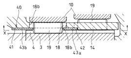
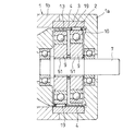
- a small diameter cylindrical surface 41 is formed on the closed end side of the cage 13, and the small diameter cylindrical surface 41 is curved with the side surface 18 a of the pocket 18 of the pocket row on the cage opening end side.
- the axial width that forms the shoulder 42 at the continuous portion of the end surface 18b, the two fixing rings 43a and 43b are sequentially press-fitted into the small-diameter cylindrical surface 41, and the front end surface in the press-fitting direction of the fixing ring 43a that has been press-fitted first is used.
- the both ends of the fixing ring 43a in the axial direction cover the entire curved end surfaces 18b of the pockets 18 of the double-row pocket row, and the fixing ring 43b is press-fitted in the press-fitting direction front side.
- the curved end surface 18b on the cage closed end side of the pocket 18 of the cage closed end side pocket row is covered with the end of the cage.
- the fixing rings 43a and 43b are press-fitted into the small-diameter cylindrical surface 41, and the end surfaces of the fixing rings 43a and 43b are covered by the ends of the fixing rings 43a and 43b. Will face the end surface 19b of the roller 19 in the axial direction, and the movement of the roller 19 in the axial direction can be restricted.
- FIGS. 13 to 16 show other examples of the restricting means 40.
- a stopper member 44 is incorporated in the curved end surface 18 b of the pocket 18.
- the stopper member 44 has a curved surface 44 a and a flat surface 44 b along the curved end surface 18 b on the outer periphery, and the flat surface 44 b is incorporated so as to face the end surface 19 b of the roller 19. Is supposed to regulate movement.
- the stopper member 44 is formed by bending a metal plate piece. However, as shown in FIG. 14, it may be formed of a synthetic resin molded product, or a rubber molded product. It may consist of. The stopper member 44 is assembled so as not to drop out of the curved end surface 18b by means of press fitting or adhesion.
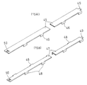
- a strip-shaped metal plate 45 having a plurality of bent pieces 46 on one side surface and a plurality of bent portions on both side surfaces.
- Two types of band-shaped metal plates are prepared, which are a band-shaped metal plate 47 that has a piece 48 and is formed such that the bent piece 48 on one side and the bent piece 48 on the other side are shifted by a half pitch position.
- Various types of metal strips 45 and 47 are wound around a small-diameter cylindrical surface 41 formed on the outer diameter surface of the cage 13.
- the band-shaped metal plate 45 shown in FIG. 15 (15A) is the press-fitting position of the fixing ring 43b shown in FIG. 9, while the band-like metal plate 47 shown in FIG. 15 (15B) is the fixing ring 43a shown in FIG.
- the press-fitting position the bent pieces 46 and 48 are fitted into the end face 19b of the pocket 18, and the protruding piece 49 formed at one end thereof is bent, and the bent protruding piece 49 is connected to the other end.
- the winding state is maintained by engaging with an engagement hole 50 provided in the pocket 18, and the amount of movement of the roller 19 in the axial direction is restricted by the bent pieces 46 and 48 disposed in the pocket 18.
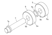
- the eccentric disk 9 is provided integrally with the input shaft 7 as in the reduction gear shown in FIG. 1, it is difficult to grind the outer diameter surface 9a into which the bearing 10 is press-fitted. Therefore, in the fifth embodiment shown in FIGS. 17 and 18, the eccentric disk 9 is separated from the input shaft 7, and the eccentric disk 9 is press-fitted into the input shaft 7 to prevent rotation.
- the flange 7a formed at the shaft end of the input shaft 7 and a spacer incorporated between the two eccentric discs 9 and between the one eccentric disc 9 and the bearing 8 supporting the input shaft 7 7b is positioned in the axial direction.
- the eccentric disc 9 Since the eccentric disc 9 is fitted by press-fitting as described above, the eccentric disc 9 is formed with a shaft insertion hole 9b at an eccentric position with respect to the outer diameter surface 9a.
- an eccentric disk element is formed by forging or pressing, and the outer diameter surface 10 of the eccentric disk element is finished by centerless grinding. You may make it form by turning.
- the outer diameter surface of the eccentric disc 9 can be easily finished by centerless grinding or the like. It is possible to reduce the processing cost.
- the detent of the eccentric disk 9 with respect to the input shaft 7 is not limited to press-fitting.
- the fitting of the input shaft 7 and the eccentric disk 9 may be a fitting of the spline 51.
Priority Applications (3)
| Application Number | Priority Date | Filing Date | Title |
|---|---|---|---|
| EP11771915.3A EP2562441B1 (de) | 2010-04-21 | 2011-04-13 | Entschleunigungsvorrichtung |
| US13/641,716 US8684878B2 (en) | 2010-04-21 | 2011-04-13 | Speed reducer |
| CN201180007961.XA CN102762891B (zh) | 2010-04-21 | 2011-04-13 | 减速装置 |
Applications Claiming Priority (6)
| Application Number | Priority Date | Filing Date | Title |
|---|---|---|---|
| JP2010097774A JP5445961B2 (ja) | 2010-04-21 | 2010-04-21 | 減速装置 |
| JP2010-097777 | 2010-04-21 | ||
| JP2010-097774 | 2010-04-21 | ||
| JP2010097777A JP2011226584A (ja) | 2010-04-21 | 2010-04-21 | 減速装置 |
| JP2010-142774 | 2010-06-23 | ||
| JP2010142774A JP2012007653A (ja) | 2010-06-23 | 2010-06-23 | 減速装置 |
Publications (1)
| Publication Number | Publication Date |
|---|---|
| WO2011132580A1 true WO2011132580A1 (ja) | 2011-10-27 |
Family
ID=44834103
Family Applications (1)
| Application Number | Title | Priority Date | Filing Date |
|---|---|---|---|
| PCT/JP2011/059155 WO2011132580A1 (ja) | 2010-04-21 | 2011-04-13 | 減速装置 |
Country Status (4)
| Country | Link |
|---|---|
| US (1) | US8684878B2 (de) |
| EP (1) | EP2562441B1 (de) |
| CN (1) | CN102762891B (de) |
| WO (1) | WO2011132580A1 (de) |
Families Citing this family (6)
| Publication number | Priority date | Publication date | Assignee | Title |
|---|---|---|---|---|
| TWI548823B (zh) * | 2015-04-14 | 2016-09-11 | 台達電子工業股份有限公司 | 減速機 |
| CN105626817A (zh) * | 2016-02-05 | 2016-06-01 | 秦皇岛博硕光电设备股份有限公司 | 一种太阳能电池串排版机及所用的滚柱活齿减速机 |
| JP6709666B2 (ja) * | 2016-04-14 | 2020-06-17 | ナブテスコ株式会社 | 歯車装置 |
| JP6989817B2 (ja) * | 2017-04-05 | 2022-01-12 | ナブテスコ株式会社 | 減速装置 |
| JP6932068B2 (ja) * | 2017-11-15 | 2021-09-08 | 住友重機械工業株式会社 | 偏心揺動型歯車装置 |
| CN115380178A (zh) * | 2020-05-06 | 2022-11-22 | Abb瑞士股份有限公司 | 变速箱壳体及其制造方法 |
Citations (6)
| Publication number | Priority date | Publication date | Assignee | Title |
|---|---|---|---|---|
| JPS59140937A (ja) * | 1983-01-31 | 1984-08-13 | Shimadzu Corp | 減速機 |
| JPS6293565A (ja) | 1985-10-18 | 1987-04-30 | Ntn Toyo Bearing Co Ltd | 減速装置 |
| JPH04219558A (ja) * | 1990-12-17 | 1992-08-10 | Aiseru Kk | 減速機 |
| WO2010018821A1 (ja) * | 2008-08-12 | 2010-02-18 | Ntn株式会社 | 可変バルブタイミング装置 |
| JP2010038362A (ja) * | 2008-07-09 | 2010-02-18 | Ntn Corp | 減速装置 |
| JP2010071462A (ja) * | 2008-08-22 | 2010-04-02 | Ntn Corp | インホイールモータ駆動装置 |
Family Cites Families (7)
| Publication number | Priority date | Publication date | Assignee | Title |
|---|---|---|---|---|
| US4584904A (en) * | 1982-03-26 | 1986-04-29 | Advanced Energy Concepts '81, Limited | Epicyclic transmission having free rolling roller driving elements |
| US4604916A (en) * | 1984-02-10 | 1986-08-12 | Advanced Energy Concepts '81 Ltd. | Epicyclic transmission having cam driven roller retainer |
| CN101101044A (zh) * | 2006-07-09 | 2008-01-09 | 杨光笋 | 有保持架单式摆线轮减速器 |
| JP5376288B2 (ja) * | 2008-08-25 | 2013-12-25 | Ntn株式会社 | 可変バルブタイミング装置 |
| WO2010004880A1 (ja) | 2008-07-09 | 2010-01-14 | Ntn株式会社 | 減速装置およびこれを適用した可変バルブタイミング装置 |
| CN201401485Y (zh) * | 2009-02-27 | 2010-02-10 | 黄立新 | 一种减速机 |
| JP5767065B2 (ja) * | 2011-09-22 | 2015-08-19 | Ntn株式会社 | 減速装置 |
-
2011
- 2011-04-13 CN CN201180007961.XA patent/CN102762891B/zh active Active
- 2011-04-13 WO PCT/JP2011/059155 patent/WO2011132580A1/ja active Application Filing
- 2011-04-13 US US13/641,716 patent/US8684878B2/en active Active
- 2011-04-13 EP EP11771915.3A patent/EP2562441B1/de active Active
Patent Citations (6)
| Publication number | Priority date | Publication date | Assignee | Title |
|---|---|---|---|---|
| JPS59140937A (ja) * | 1983-01-31 | 1984-08-13 | Shimadzu Corp | 減速機 |
| JPS6293565A (ja) | 1985-10-18 | 1987-04-30 | Ntn Toyo Bearing Co Ltd | 減速装置 |
| JPH04219558A (ja) * | 1990-12-17 | 1992-08-10 | Aiseru Kk | 減速機 |
| JP2010038362A (ja) * | 2008-07-09 | 2010-02-18 | Ntn Corp | 減速装置 |
| WO2010018821A1 (ja) * | 2008-08-12 | 2010-02-18 | Ntn株式会社 | 可変バルブタイミング装置 |
| JP2010071462A (ja) * | 2008-08-22 | 2010-04-02 | Ntn Corp | インホイールモータ駆動装置 |
Non-Patent Citations (1)
| Title |
|---|
| See also references of EP2562441A4 * |
Also Published As
| Publication number | Publication date |
|---|---|
| US20130035191A1 (en) | 2013-02-07 |
| CN102762891A (zh) | 2012-10-31 |
| EP2562441A1 (de) | 2013-02-27 |
| CN102762891B (zh) | 2015-09-23 |
| EP2562441A4 (de) | 2013-10-16 |
| US8684878B2 (en) | 2014-04-01 |
| EP2562441B1 (de) | 2014-11-19 |
Similar Documents
| Publication | Publication Date | Title |
|---|---|---|
| WO2011132580A1 (ja) | 減速装置 | |
| EP1830084B1 (de) | Lagervorrichtung für fahrzeug | |
| JP4581542B2 (ja) | 回転支持装置 | |
| EP2706265B1 (de) | Drehzahlminderer | |
| JP2022048250A (ja) | 旋回軸受 | |
| JP2010096308A (ja) | 伸縮式回転伝達軸 | |
| JP5445961B2 (ja) | 減速装置 | |
| WO2017063489A1 (zh) | 全齿啮合传动方法及装置 | |
| US10253853B2 (en) | Stepless transmission | |
| JP2007292195A (ja) | 深溝玉軸受 | |
| JP2011085153A (ja) | 転がり軸受 | |
| JP5273442B2 (ja) | ラジアル針状ころ軸受 | |
| US10900553B2 (en) | Planetary power transmission device | |
| JP5083157B2 (ja) | 伸縮式回転伝達軸 | |
| JP5939086B2 (ja) | 転がり軸受装置 | |
| JP4904980B2 (ja) | 車軸用軸受装置 | |
| JP7202171B2 (ja) | 軸受装置 | |
| JP2013024291A (ja) | 減速装置 | |
| CN211231515U (zh) | 减速机偏心传动机构 | |
| WO2023079641A1 (ja) | 波動歯車装置 | |
| JP6839919B2 (ja) | 回転軸構造 | |
| JP7364420B2 (ja) | 動力伝達装置 | |
| CN108884864B (zh) | 圆锥滚子轴承 | |
| JP6351645B2 (ja) | 回転軸構造 | |
| JP2012007653A (ja) | 減速装置 |
Legal Events
| Date | Code | Title | Description |
|---|---|---|---|
| WWE | Wipo information: entry into national phase |
Ref document number: 201180007961.X Country of ref document: CN |
|
| 121 | Ep: the epo has been informed by wipo that ep was designated in this application |
Ref document number: 11771915 Country of ref document: EP Kind code of ref document: A1 |
|
| WWE | Wipo information: entry into national phase |
Ref document number: 13641716 Country of ref document: US |
|
| NENP | Non-entry into the national phase |
Ref country code: DE |
|
| WWE | Wipo information: entry into national phase |
Ref document number: 2011771915 Country of ref document: EP |