WO2011132433A1 - 電子レンジ調理用袋 - Google Patents
電子レンジ調理用袋 Download PDFInfo
- Publication number
- WO2011132433A1 WO2011132433A1 PCT/JP2011/002373 JP2011002373W WO2011132433A1 WO 2011132433 A1 WO2011132433 A1 WO 2011132433A1 JP 2011002373 W JP2011002373 W JP 2011002373W WO 2011132433 A1 WO2011132433 A1 WO 2011132433A1
- Authority
- WO
- WIPO (PCT)
- Prior art keywords
- opening
- side seal
- cooking bag
- main body
- microwave oven
- Prior art date
- Legal status (The legal status is an assumption and is not a legal conclusion. Google has not performed a legal analysis and makes no representation as to the accuracy of the status listed.)
- Ceased
Links
Images


Classifications
-
- B—PERFORMING OPERATIONS; TRANSPORTING
- B65—CONVEYING; PACKING; STORING; HANDLING THIN OR FILAMENTARY MATERIAL
- B65D—CONTAINERS FOR STORAGE OR TRANSPORT OF ARTICLES OR MATERIALS, e.g. BAGS, BARRELS, BOTTLES, BOXES, CANS, CARTONS, CRATES, DRUMS, JARS, TANKS, HOPPERS, FORWARDING CONTAINERS; ACCESSORIES, CLOSURES, OR FITTINGS THEREFOR; PACKAGING ELEMENTS; PACKAGES
- B65D81/00—Containers, packaging elements, or packages, for contents presenting particular transport or storage problems, or adapted to be used for non-packaging purposes after removal of contents
- B65D81/34—Containers, packaging elements, or packages, for contents presenting particular transport or storage problems, or adapted to be used for non-packaging purposes after removal of contents for packaging foodstuffs or other articles intended to be cooked or heated within the package
- B65D81/3446—Containers, packaging elements, or packages, for contents presenting particular transport or storage problems, or adapted to be used for non-packaging purposes after removal of contents for packaging foodstuffs or other articles intended to be cooked or heated within the package specially adapted to be heated by microwaves
- B65D81/3461—Flexible containers, e.g. bags, pouches, envelopes
-
- B—PERFORMING OPERATIONS; TRANSPORTING
- B65—CONVEYING; PACKING; STORING; HANDLING THIN OR FILAMENTARY MATERIAL
- B65D—CONTAINERS FOR STORAGE OR TRANSPORT OF ARTICLES OR MATERIALS, e.g. BAGS, BARRELS, BOTTLES, BOXES, CANS, CARTONS, CRATES, DRUMS, JARS, TANKS, HOPPERS, FORWARDING CONTAINERS; ACCESSORIES, CLOSURES, OR FITTINGS THEREFOR; PACKAGING ELEMENTS; PACKAGES
- B65D33/00—Details of, or accessories for, sacks or bags
- B65D33/16—End- or aperture-closing arrangements or devices
- B65D33/25—Riveting; Dovetailing; Screwing; using press buttons or slide fasteners
- B65D33/2508—Riveting; Dovetailing; Screwing; using press buttons or slide fasteners using slide fasteners with interlocking members having a substantially uniform section throughout the length of the fastener; Sliders therefor
-
- B—PERFORMING OPERATIONS; TRANSPORTING
- B65—CONVEYING; PACKING; STORING; HANDLING THIN OR FILAMENTARY MATERIAL
- B65D—CONTAINERS FOR STORAGE OR TRANSPORT OF ARTICLES OR MATERIALS, e.g. BAGS, BARRELS, BOTTLES, BOXES, CANS, CARTONS, CRATES, DRUMS, JARS, TANKS, HOPPERS, FORWARDING CONTAINERS; ACCESSORIES, CLOSURES, OR FITTINGS THEREFOR; PACKAGING ELEMENTS; PACKAGES
- B65D75/00—Packages comprising articles or materials partially or wholly enclosed in strips, sheets, blanks, tubes or webs of flexible sheet material, e.g. in folded wrappers
- B65D75/008—Standing pouches, i.e. "Standbeutel"
-
- B—PERFORMING OPERATIONS; TRANSPORTING
- B65—CONVEYING; PACKING; STORING; HANDLING THIN OR FILAMENTARY MATERIAL
- B65D—CONTAINERS FOR STORAGE OR TRANSPORT OF ARTICLES OR MATERIALS, e.g. BAGS, BARRELS, BOTTLES, BOXES, CANS, CARTONS, CRATES, DRUMS, JARS, TANKS, HOPPERS, FORWARDING CONTAINERS; ACCESSORIES, CLOSURES, OR FITTINGS THEREFOR; PACKAGING ELEMENTS; PACKAGES
- B65D2205/00—Venting means
Definitions
- the present invention relates to a self-standing pouch-shaped microwave cooking bag for enclosing foods such as ingredients and seasoning liquids and cooking by heating with a microwave oven.
- Patent Document 1 discloses a self-supporting pouch 400 shown in FIG.
- the self-standing pouch 400 includes a chuck 401 for opening and closing, and a portion other than the chuck on the outer edge of the main body film 402 is sealed leaving a part of the unsealed portion 403, and a housing portion 404 is formed by the chuck and the seal.
- the steam generated in the housing part 404 escapes from the unsealed part 403. Thereby, the breakage of the self-standing pouch 400 due to an increase in the pressure inside the housing portion 404 can be prevented.
- Patent Document 2 discloses a self-supporting pouch 500 shown in FIG.
- the self-standing pouch 500 includes a housing portion 504 formed by sealing the outer edge of the main body film 502 in a band shape, and a right-angled steaming portion 505 that protrudes from the outer edge with a corner portion toward the housing portion 504.
- the seal part of the steaming part 505 is selectively peeled off, a steaming port is formed, and the steam escapes (is steamed).
- Patent Documents 3 to 6 also disclose heatable pouches.
- a self-standing pouch such as the self-standing pouch 500, in which the seal peels off due to the pressure of steam during heating and the steaming port appears, the contents are accommodated.
- the product was sealed, and once opened, it could not be resealed, and the user could not heat the contents to be heated.
- an object of the present invention is to provide a self-supporting microwave cooking bag that can be heated while putting contents to be heated by a user and preventing breakage due to steam.
- the present invention is formed by partially inserting a bottom tape material folded in half between two main body films from the crease portion and heat-sealing the peripheral edge except for the upper end edge.
- a microwave cooking bag that can be heated by a microwave oven in a housed state, and has an opening formed by sealing a chuck at the upper edge portion of two main body films, and a bottom seal having a wider width than the opening
- a first side seal portion formed from the bottom seal portion to one end of the opening, and a second side seal portion formed from the bottom seal portion to a position lower than the upper end of the first side seal portion; , From the upper end of the second side seal portion, the corner portion formed by cutting out the two main body films in a shape projecting inward at an acute angle, and the opening portion from the upper end of the second side seal portion Or the other end of And a third side seal portion formed along the corner portion, and at least a portion near the tip of the corner portion of the third side seal portion is sealed with a seal strength smaller than the internal fitting strength of the
- a microwave oven cooking bag can be provided.
- FIG. 1 is a plan view of a microwave cooking bag according to an embodiment of the present invention.
- FIG. 2 is a cross-sectional view of the microwave oven cooking bag according to one embodiment of the present invention along the line AA ′ of FIG.
- FIG. 3 is a diagram showing the state of steaming of the microwave cooking bag according to one embodiment of the present invention.
- FIG. 4 is an enlarged view of the steaming part of the microwave oven cooking bag according to one embodiment and another embodiment of the present invention.
- FIG. 5 is a diagram illustrating a conventional microwave cooking bag.
- FIG. 6 is a diagram illustrating a conventional microwave cooking bag.
- FIG. 1 the top view of the bag 100 for microwave oven cooking of this invention is shown.
- FIG. 2 is a cross-sectional view taken along the line AA ′ in FIG.
- the microwave cooking bag 100 is manufactured from two main body films 101 and 102, a bottom tape material 103, and a chuck 104 as shown in FIG. 2.
- these materials include a laminated film having a layer structure of polyethylene terephthalate 12 ⁇ m / stretched nylon 15 ⁇ m / unstretched polypropylene 60 ⁇ m from the outer surface to the inside of the microwave cooking bag 100.
- the material is not limited to this, it has a certain strength, does not contain metal so that it can be used in a microwave oven, and has a certain heat resistance, and the innermost layer can be heat sealed, And what is necessary is just to have fixed acid resistance, oil resistance, etc.
- the bottom tape material 103 folded in half is partially inserted from the crease portion.
- a chuck 104 is sealed on the upper end side of the peripheral edge of the portion where the two main body films 101 and 102 overlap. This portion becomes the opening 105.
- the left and right end sides of the peripheral portion of the portion where the two main body films 101 and 102 overlap each other are sealed to form a first side seal portion 121 and a second side seal portion 122.
- the peripheral portion of the portion where the two main body films 101 and 102 and the bottom tape material 103 overlap is also subjected to a sealing process to form a bottom seal portion 107.
- the height of the upper end of the second side seal portion 122 is lower than the height of the upper end of the first side seal portion. Further, the width of the opening 105 is smaller than the width of the bottom seal portion 107. Therefore, one end of the opening 105 is connected to the upper end of the first side seal part 121, but the other end is not connected to the upper end of the second side seal part 122.
- the portion from the upper end of the second side seal part 122 to the other end of the opening 105 is cut out in a shape that projects the main body films 101 and 102 in an acute angle toward the inside of the microwave cooking bag 100. Corner portions 110 are formed. A peripheral portion along the corner portion 110 is formed with a third side seal portion 123 by sealing the main body films 101 and 102. A portion including the vicinity of the tip of the corner portion 110 of the third side seal portion 123 is formed with a steaming portion 109 that is heat-sealed with a seal strength smaller than the internal fitting strength of the chuck 104.
- zipper here means the structure where a protruding item
- the internal fitting strength of the chuck refers to a tensile force that actually causes dissociation when a tensile force that dissociates the protrusions and recesses of the chuck 104 is applied to the chuck 104, particularly from the inside, that is, from the housing portion 108 side. The strength of power.
- the portion surrounded by the first to third side seal portions 121, 122, and 123 and the bottom seal portion 107 is the accommodating portion 108.
- the container 108 is opened and sealed by opening and closing the chuck 104, and the contents can be taken in and out by the user.
- the microwave cooking bag 100 has a height of about 150 mm and a width of about 240 mm, and the opening 105 has a width of about 150 mm.
- the microwave oven can be put into a microwave oven and the contents can be taken in and out. Other sizes may be used as long as they are easy to do.
- an unsealed portion 116 that is a portion where heat sealing processing is not performed is provided.
- the unsealed portion 116 relieves unevenness and thermal curl due to thermal shrinkage during the heat sealing process, and improves the stability and appearance of the seal and the strength when dropped.
- a main body film seal portion 117 in which the main body films 101 and 102 are heat-sealed with each other is provided on the left and right peripheral edge portions of the bottom seal portion 107.
- the main body film seal portion 117 is formed by punching the bottom tape material 103 and providing holes or notches so that the sealant layers of the main body films 101 and 102 are directly sealed during the sealing process. .
- the left and right ends of the bottom seal portion 107 are prevented from opening, and the appearance of the microwave cooking bag 100 and the self-supporting stability are maintained.
- the handle 111 is formed. Since the handle 111 has a smaller heat capacity and cools faster than the storage unit 108 in which the contents are stored, after the microwave cooking bag 100 is heated, the user has the handle 111 from inside the microwave oven. Therefore, the risk of burns such as fingers can be reduced.
- a tab 114 is formed on the main body films 101 and 102 at the upper end of the opening 105. The user can easily open the chuck 104 by pinching the tab 114.
- At least one of the main body films 101 and 102 is drawn with a reference line 115 that is a line that serves as a reference for an appropriate amount when a liquid content such as seasoning liquid is added.
- the position of the reference line 115 is about 30 to 40% of the height of the microwave cooking bag.
- the sealing process of the vapor passage unit 109 is performed so that the sealing strength is weaker than the internal fitting strength of the chuck 104. Therefore, compared with the heat sealing process of other sealing parts, the number of processes is reduced or the process is performed at a low temperature to perform the weak sealing process. In addition, an irregular sealing process may be performed so that the seal is easily peeled from the corner portion 110 toward the opening 105 side and the second side seal portion 122.
- the steaming section 109 is a corner section 110 that is weakly sealed by the pressure of steam when contents (not shown) such as ingredients and seasoning liquid are put into the microwave cooking bag 100 and heated. And the main body films 101 and 102 in the vicinity thereof are peeled off, and the steam inlet 112 appears.
- the angle formed by the corner portion 110 of the steam passage portion 109 illustrated in FIG. 1 as the present embodiment is an acute angle of about 75 °.
- container 108 is inflated by the steam.
- the peeling of the seal is started from the tip portion.
- the peeling of the seal progresses, and the peeling boundary moves backward from the tip, but the smaller the angle formed by the corner 110, the shorter the length of the peeling boundary line, and the concentration of the tensile force at the peeling progress position is Get higher. Therefore, in this embodiment, the angle formed by the corner portion 110 of the vapor passage section 109 is an acute angle so that the seal is easily peeled off and the vapor passage opening 112 is easily formed.
- FIG. 4A shows an enlarged view of a portion including the steaming portion 109 of the microwave cooking bag 100.
- the vapor passage 109 is provided with a notch 113 so that the width of the sealed portion is reduced and the seal is more easily peeled off.
- FIG. 4B shows a steaming section 150 in which the notch 113 is not provided and an unsealed part 151 is provided at the same location.
- the unsealed portion 151 By providing the unsealed portion 151 in this way, it is possible to reduce the width of the sealed portion.
- the steaming part 109 provided with the notch 113 is adopted instead of the unsealed part 151.
- the sealing strength of the vapor passage section 109 is in the range of 10.0 to 15.2 (N / 15 mm), and the internal fitting strength of the chuck 104 is 17.8 to 27.6 (N / 15 mm). In this range, the sealing strength of the vapor passage portion 109 is made weaker than the internal fitting strength of the chuck 104.
- the chuck 104 is closed, put in the microwave oven, and heated at an output of 600 W for about 10 minutes, the steam inlet 112 appears and is steamed. Was confirmed. Moreover, it was confirmed that the contents of the microwave cooking bag were cooked without problems as boiled food (meat potatoes).
- the pressure in the container 108 can be reduced by steaming to prevent the microwave cooking bag 100 from being damaged, and a constant pressure is maintained even after steaming, and steaming under the pressure is performed. It was confirmed that cooking was possible.
- the above-described materials, shapes, dimensions, seal strength, etc. of the microwave cooking bag 100 are merely examples. These are guidelines for obtaining effects such as use in a microwave oven, ease of taking in and out of contents, appearance of a steaming opening, steaming cooking under a constant pressure, and equivalent effects are obtained. As long as it is not limited to the above example.
- the present invention is useful for a packaging for microwave oven cooking such as a pouch that can be sealed by sealing the contents, and in particular, can be cooked while preventing damage to the packaging due to steam generated from ingredients, etc. by heating. It is useful for a freestanding microwave cooking bag.
- Microwave cooking bag 400 500 Self-standing pouch 101, 102, 402, 502 Main film 103 Bottom tape material 104, 401 Chuck 105 Opening 107 Bottom seal part 108, 404, 504 Housing part 109, 150, 505 Steaming part 110 corner portion 111 handle 112 fume port 113 notch 114 tab 115 guide line 116, 151 unsealed portion 117 main body film seal portion 121 first side seal portion 122 second side seal portion 123 third side seal portion 403 Unsealed part
Landscapes
- Engineering & Computer Science (AREA)
- Mechanical Engineering (AREA)
- Life Sciences & Earth Sciences (AREA)
- Food Science & Technology (AREA)
- Bag Frames (AREA)
- Package Specialized In Special Use (AREA)
Abstract
2枚の本体フィルムの上端縁部分にチャックをシールして形成した開口部と、開口部より広い幅を有する底シール部と、底シール部から開口部の一方端にかけて形成された第1のサイドシール部と、底シール部から第1のサイドシール部の上端より低い位置にかけて形成された第2のサイドシール部と、第2のサイドシール部の上端から、2枚の本体フィルムを、内方側に鋭角に突出する形状で切り欠くことで形成された角部と、第2のサイドシール部の上端から開口部の他方端にかけて、角部に沿って形成された第3のサイドシール部とを備え、第3のサイドシール部のうち、少なくとも角部の先端近傍には、チャックの内嵌合強度より小さなシール強度でシールされる通蒸部が設けられる。
Description
本発明は、食材や調味液などの食品等を封入し電子レンジにより加熱調理するための自立パウチ形状の電子レンジ調理用袋に関する。
従来、食品等の内容物を予め内部に封入した状態で電子レンジによる加熱が可能なパウチが提案されている。特許文献1は、図5に示す自立パウチ400を開示している。自立パウチ400は、開閉用のチャック401を備え、本体フィルム402の外縁のチャック以外の部分は、一部の未シール部403を残してシールされており、チャックとシールとによって収容部404が形成されている。加熱の際、収容部404で発生した蒸気は、未シール部403から抜け出る。これにより、収容部404内部の圧力の上昇による自立パウチ400の破損を防止できる。
また、特許文献2は図6に示す自立パウチ500を開示している。自立パウチ500は、本体フィルム502の外縁を帯状にシールすることで形成した収容部504と、外縁から収容部504側に角部を有して突出する直角の通蒸部505を備えている。加熱の際、収容部504で発生した蒸気が一定圧力を超えると、通蒸部505のシール部が選択的に剥離し、通蒸口が形成され、蒸気が抜け出る(通蒸される)。これにより、自立パウチ500の予定しない箇所から蒸気が漏出し、自立パウチ500を破損したり、その周囲を汚損することを防止できる。また、特許文献3~6も、加熱可能なパウチを開示している。
しかしながら、従来のパウチのうち、自立パウチ500のような、自立型のパウチであって加熱時の蒸気による圧力でシールが剥離し通蒸口が現出する態様のものは、内容物が収容された状態で封止されており、一度開封すると再封止はできず、使用者が加熱したい内容物を入れて加熱することはできなかった。
それ故に、本発明の目的は、使用者が加熱したい内容物を入れて、蒸気による破損を防止しつつ加熱することが可能な自立可能な電子レンジ調理用袋を提供することである。
本発明は、2枚の本体フィルムの間に、2つ折りにした底テープ材を折り目部分から部分的に挿入し、上端縁を除く周縁部を熱シールすることによって形成され、内部に内容物を収容した状態で電子レンジによる加熱が可能な電子レンジ調理用袋であって、2枚の本体フィルムの上端縁部分にチャックをシールして形成した開口部と、開口部より広い幅を有する底シール部と、底シール部から開口部の一方端にかけて形成された第1のサイドシール部と、底シール部から第1のサイドシール部の上端より低い位置にかけて形成された第2のサイドシール部と、第2のサイドシール部の上端から、2枚の本体フィルムを、内方側に鋭角に突出する形状で切り欠くことで形成された角部と、第2のサイドシール部の上端から開口部の他方端にかけて、角部に沿って形成された第3のサイドシール部とを備え、第3のサイドシール部のうち、少なくとも角部の先端近傍には、チャックの内嵌合強度より小さなシール強度でシールされる通蒸部が設けられている。
本発明によれば、使用者が電子レンジを用いて加熱調理したい食材や調味液などの内容物を入れて、内部に生ずる蒸気による袋の破損を防止しつつ電子レンジによる加熱をすることが可能な電子レンジ調理用袋を提供できる。
本発明の実施形態を説明する。図1に、本発明の電子レンジ調理用袋100の平面図を示す。また、図1のA-A´線に沿った断面図を図2に示す。電子レンジ調理用袋100は、従来の自立パウチと同様、図2に示すように、2枚の本体フィルム101および102と、底テープ材103と、チャック104とから製造される。これらの材質としては、電子レンジ調理用袋100の外部表面から内部にかけて、ポリエチレンテレフタラート12μm/延伸ナイロン15μm/無延伸ポリプロピレン60μmの層構成の積層フィルムが挙げられる。材質は、これに限らず、一定の強度があること、電子レンジで使用できるように金属を含まないこと、かつ、一定の耐熱性があること、また、最内層が熱シール処理可能であり、かつ、一定の耐酸性、耐油性等を備えていればよい。
2枚の本体フィルム101および102の間には、2つ折りにした底テープ材103が折り目部分から部分的に挿入されている。2枚の本体フィルム101および102が重なり合う部分の周縁部の上端側には、チャック104がシールされている。この部分が開口部105となる。図1に示すように、2枚の本体フィルム101および102が重なり合う部分の周縁部の左右端側は、互いにシール処理されて第1のサイドシール部121および第2のサイドシール部122が形成されている。2枚の本体フィルム101および102と底テープ材103とが重なり合う部分の周縁部も、シール処理され、底シール部107が形成されている。第2のサイドシール部122の上端の高さは、第1のサイドシール部の上端の高さより低い。また、開口部105の幅は、底シール部107の幅より小さい。そのため、開口部105の一方端は、第1のサイドシール部121の上端に接続されているが、他方端は、第2のサイドシール部122の上端に接続されていない。第2のサイドシール部122の上端から開口部105の他方端にかけての部分は、本体フィルム101および102を、電子レンジ調理用袋100の内方に向けて鋭角に突出する形状で切り欠くことで角部110が形成されている。角部110に沿う周縁部分は、本体フィルム101および102がシールされることにより第3のサイドシール部123が形成されている。第3のサイドシール部123の角部110の先端近傍を含む部分は、チャック104の内嵌合強度より小さなシール強度で熱シールされた通蒸部109が形成されている。
なお、ここでいうチャックとは、凸条と凹条とが対向して形成され、繰り返し互いに嵌合および解離することが可能な構造をいう。また、チャックの内嵌合強度とは、チャック104の凸条と凹条と解離させる引張り力を、とくに内側、すなわち収容部108側からチャック104に加えたときに、実際に解離が発生する引張り力の強さをいう。
第1~第3のサイドシール部121、122および123と底シール部107とによって囲まれた部分が、収容部108となる。収容部108は、チャック104の開閉により、開封および封止され、使用者による内容物の出し入れが可能となっている。本実施形態として、電子レンジ調理用袋100のサイズを高さ150mm、幅240mm程度とし、開口部105の幅は150mm程度としたが、電子レンジに入れることができ、かつ、内容物の出し入れがしやすい範囲であれば、これ以外の大きさでもよい。
底シール部107が形成された領域の内部には、熱シール処理を行わない部分である未シール部116が設けられている。この未シール部116によって、熱シール処理時の熱収縮による凹凸や熱カールを緩和して、シールの安定性および見映え、さらには落下時の強度を向上している。
また、底シール部107の左右周縁部には、本体フィルム101および102が互いに熱シール処理されている本体フィルムシール部117が設けられている。本体フィルムシール部117は、底テープ材103をパンチ加工して、穴あるいは切り欠きを設けておき、シール処理時に、本体フィルム101および102のシーラント層どうしが直接シールされるようにしたものである。これにより、底シール部107の左右両端部分が開くことを防止し、電子レンジ調理用袋100の見映えの良好さと自立安定性とを維持している。
第1および第2のサイドシール部121および122のうち、上端を含む一部分は、他の部分に比べて、大きな幅にわたって、熱シール処理され、持ち手111が形成されている。持ち手111は、内容物が収容された収容部108に比べ、熱容量が小さく、早く冷めるため、電子レンジ調理用袋100の加熱後、電子レンジ庫内から使用者がその持ち手111を持つことで、指などの火傷の危険を低減できる。
開口部105の上端には、本体フィルム101および102にタブ114が形成されている。使用者はタブ114をつまむことにより、チャック104を容易に開けることができる。
また、本体フィルム101および102の少なくとも一方には、調味液等の液体の内容物を入れる際の適量の目安となる線である目安線115が描かれている。本実施形態では、目安線115の位置は、電子レンジ調理用袋の高さの30~40パーセント程度の位置としている。これにより、使用者は、目安線115の高さを越える液体を入れないように注意することができ、加熱調理時に通蒸口112からの吹きこぼれを防止できる。
通蒸部109のシール処理は、シール強度がチャック104の内嵌合強度より弱くなるように行う。そのため、他のシール部分の熱シール処理に比べて、処理回数を減らしたり、低温で処理したりして、弱シール処理を行う。また、角部110から開口部105側および第2のサイドシール部122に向けてシールが剥離しやすくなるよう、異形シール処理を行ってもよい。通蒸部109は、図3に示すように電子レンジ調理用袋100に食材や調味液等の内容物(不図示)を入れて加熱した際、蒸気の圧力によって、弱シールとした角部110およびその近傍の本体フィルム101および102が剥離して、通蒸口112が現出する。
本実施形態として図1に例示する通蒸部109の角部110が形成する角度は、およそ75°の鋭角となっている。電子レンジ調理用袋100が加熱されると、蒸気により収容部108が膨らむ。このとき、本体フィルム101と102とを引き離す方向の引張り力が、まず収容部108の中央部に近い角部110の先端部に集中するため、先端部からシールの剥離が開始される。その後、シールの剥離が進行し、剥離境界が先端部から後退するが、角部110が形成する角度が小さいほど、剥離境界線の長さが短くなり、剥離進行位置における引張り力の集中度は高くなる。そのため、本実施形態では、通蒸部109の角部110が形成する角度を鋭角とすることで、シールが剥離しやすく、通蒸口112が形成されやすいようにしている。
図4の(a)に、電子レンジ調理用袋100の通蒸部109を含む部分の拡大図を示す。通蒸部109には、シールされた部分の幅を小さくして、よりシールが剥離しやすくなるよう、切欠き113が設けられている。図4の(b)に、切欠き113を設けず、同一箇所に未シール部151を設けた通蒸部150を示す。このように未シール部151を設けることによっても、シールされた部分の幅を小さくすることは可能である。しかしながら、この場合、現出した通蒸口から抜け出た蒸気が未シール部151で液化し、通蒸口を塞ぐおそれがある。このため、本実施形態の電子レンジ調理用袋100では、未シール部151ではなく、切欠き113を設けた通蒸部109を採用している。
本実施形態では、通蒸部109のシール強度は10.0~15.2(N/15mm)の範囲とし、チャック104の内嵌合強度は、17.8~27.6(N/15mm)の範囲とし、通蒸部109のシール強度がチャック104の内嵌合強度より弱くなるようにした。
本発明の効果を検証するため、本実施形態の電子レンジ調理用袋を用いて加熱調理を行った。内容物とする食材および調味液は表1に示すとおりである。

これらの内容物を電子レンジ調理用袋100に入れ、チャック104を閉じて、電子レンジに入れ、出力600Wで10分間ほど加熱を行ったところ、通蒸口112が現出し、通蒸されることが確認できた。また、電子レンジ調理用袋の内容物は、煮物(肉じゃが)として問題なく加熱調理されていることが確認できた。
また、このような通蒸口112が現出するケースについて、収容部108の内外の圧力差を測定し、5回の試行中、表2に示す結果を得た。
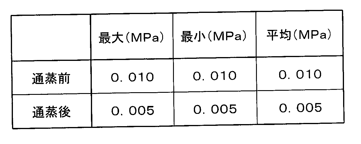
このように通蒸によって、収容部108内の圧力を低下させ、電子レンジ調理用袋100が破損するのを防止できること、および通蒸後も、一定の圧力が維持され、当該圧力下での蒸らし調理が可能であることが確認できた。
電子レンジ調理用袋100の上述した材質、形状、寸法、シール強度等は、一例にすぎない。これらは、電子レンジでの使用、内容物の出し入れのしやすさ、通蒸口の現出、一定圧力下での蒸らし調理等の効果を得るうえでの目安であり、同等の効果が得られる限り、上述の例に限定されない。
本発明は、内容物を封入し密封可能なパウチ等の電子レンジ調理用包装体に有用であり、とくに、加熱により食材等から生じる蒸気による包装体の破損を防止しつつ加熱調理することが可能な自立型の電子レンジ調理用袋に有用である。
100 電子レンジ調理用袋
400、500 自立パウチ
101、102、402、502 本体フィルム
103 底テープ材
104、401 チャック
105 開口部
107 底シール部
108、404、504 収容部
109、150、505 通蒸部
110 角部
111 持ち手
112 通蒸口
113 切込み
114 タブ
115 目安線
116、151 未シール部
117 本体フィルムシール部
121 第1のサイドシール部
122 第2のサイドシール部
123 第3のサイドシール部
403 未シール部
400、500 自立パウチ
101、102、402、502 本体フィルム
103 底テープ材
104、401 チャック
105 開口部
107 底シール部
108、404、504 収容部
109、150、505 通蒸部
110 角部
111 持ち手
112 通蒸口
113 切込み
114 タブ
115 目安線
116、151 未シール部
117 本体フィルムシール部
121 第1のサイドシール部
122 第2のサイドシール部
123 第3のサイドシール部
403 未シール部
Claims (4)
- 2枚の本体フィルムの間に、2つ折りにした底テープ材を折り目部分から部分的に挿入し、上端縁を除く周縁部を熱シールすることによって形成され、内部に内容物を収容した状態で電子レンジによる加熱が可能な電子レンジ調理用袋であって、
前記2枚の本体フィルムの上端縁部分にチャックをシールして形成した開口部と、
前記開口部より広い幅を有する底シール部と、
前記底シール部から前記開口部の一方端にかけて形成された第1のサイドシール部と、
前記底シール部から前記第1のサイドシール部の上端より低い位置にかけて形成された第2のサイドシール部と、
前記第2のサイドシール部の上端から、前記2枚の本体フィルムを、内方側に鋭角に突出する形状で切り欠くことで形成された角部と、
前記第2のサイドシール部の上端から前記開口部の他方端にかけて、前記角部に沿って形成された第3のサイドシール部とを備え、
前記第3のサイドシール部のうち、少なくとも前記角部の先端近傍には、前記チャックの内嵌合強度より小さなシール強度でシールされる通蒸部が設けられる、電子レンジ調理用袋。 - 前記第1および第2のサイドシール部の上端を含む部分は、他の部分に比べて広い幅を有する、請求項1に記載の電子レンジ調理用袋。
- 前記開口部の上端には、タブが形成されている、請求項1または2に記載の電子レンジ調理用袋。
- 前記2枚の本体フィルムの少なくとも一方には、液体の内容物を入れる際の適量の目安となる線が描かれている、請求項1~3のいずれかに記載の電子レンジ調理用袋。
Applications Claiming Priority (2)
| Application Number | Priority Date | Filing Date | Title |
|---|---|---|---|
| JP2010100029A JP2011230775A (ja) | 2010-04-23 | 2010-04-23 | 電子レンジ調理用袋 |
| JP2010-100029 | 2010-04-23 |
Publications (1)
| Publication Number | Publication Date |
|---|---|
| WO2011132433A1 true WO2011132433A1 (ja) | 2011-10-27 |
Family
ID=44833974
Family Applications (1)
| Application Number | Title | Priority Date | Filing Date |
|---|---|---|---|
| PCT/JP2011/002373 Ceased WO2011132433A1 (ja) | 2010-04-23 | 2011-04-22 | 電子レンジ調理用袋 |
Country Status (2)
| Country | Link |
|---|---|
| JP (1) | JP2011230775A (ja) |
| WO (1) | WO2011132433A1 (ja) |
Cited By (2)
| Publication number | Priority date | Publication date | Assignee | Title |
|---|---|---|---|---|
| JP2011230775A (ja) * | 2010-04-23 | 2011-11-17 | Toppan Printing Co Ltd | 電子レンジ調理用袋 |
| WO2013180669A1 (en) * | 2012-05-29 | 2013-12-05 | Wongprasertphol Pornchai | Packaging bag with carrying handle |
Families Citing this family (1)
| Publication number | Priority date | Publication date | Assignee | Title |
|---|---|---|---|---|
| CN105775353B (zh) | 2012-02-03 | 2019-04-12 | 凸版印刷株式会社 | 袋子及密封有内容物的袋子 |
Citations (12)
| Publication number | Priority date | Publication date | Assignee | Title |
|---|---|---|---|---|
| JPH0243286U (ja) * | 1988-09-19 | 1990-03-26 | ||
| JPH03121460U (ja) * | 1990-03-23 | 1991-12-12 | ||
| JPH0410079U (ja) * | 1990-05-15 | 1992-01-28 | ||
| JP2000327046A (ja) * | 1999-05-17 | 2000-11-28 | Dainippon Printing Co Ltd | 咬合具付きスタンディングパウチ |
| JP2000335593A (ja) * | 1999-05-28 | 2000-12-05 | Dainippon Printing Co Ltd | 電子レンジ加熱用袋 |
| JP2002225890A (ja) * | 2000-12-01 | 2002-08-14 | Dainippon Printing Co Ltd | 咬合具付き袋 |
| JP2004051129A (ja) * | 2002-07-17 | 2004-02-19 | Toyo Seikan Kaisha Ltd | 閉塞部材付きパウチ |
| JP2005047598A (ja) * | 2003-07-31 | 2005-02-24 | Toppan Printing Co Ltd | 蒸気抜き機能を有する包装袋とそれを用いた包装体 |
| JP2005075426A (ja) * | 2003-09-02 | 2005-03-24 | Toyo Seikan Kaisha Ltd | 電子レンジ用包装袋 |
| JP2007297081A (ja) * | 2006-04-28 | 2007-11-15 | Toppan Printing Co Ltd | 包装袋及び包装体 |
| JP2009274771A (ja) * | 2009-08-26 | 2009-11-26 | Kyodo Printing Co Ltd | 電子レンジ用包装袋 |
| JP2010036968A (ja) * | 2008-08-07 | 2010-02-18 | Toppan Printing Co Ltd | 蒸気抜き自立包装袋 |
Family Cites Families (2)
| Publication number | Priority date | Publication date | Assignee | Title |
|---|---|---|---|---|
| JPH11189278A (ja) * | 1997-12-25 | 1999-07-13 | Sanyo Engineering Kk | 電子レンジ対応の食材包装容器 |
| JP2011230775A (ja) * | 2010-04-23 | 2011-11-17 | Toppan Printing Co Ltd | 電子レンジ調理用袋 |
-
2010
- 2010-04-23 JP JP2010100029A patent/JP2011230775A/ja active Pending
-
2011
- 2011-04-22 WO PCT/JP2011/002373 patent/WO2011132433A1/ja not_active Ceased
Patent Citations (12)
| Publication number | Priority date | Publication date | Assignee | Title |
|---|---|---|---|---|
| JPH0243286U (ja) * | 1988-09-19 | 1990-03-26 | ||
| JPH03121460U (ja) * | 1990-03-23 | 1991-12-12 | ||
| JPH0410079U (ja) * | 1990-05-15 | 1992-01-28 | ||
| JP2000327046A (ja) * | 1999-05-17 | 2000-11-28 | Dainippon Printing Co Ltd | 咬合具付きスタンディングパウチ |
| JP2000335593A (ja) * | 1999-05-28 | 2000-12-05 | Dainippon Printing Co Ltd | 電子レンジ加熱用袋 |
| JP2002225890A (ja) * | 2000-12-01 | 2002-08-14 | Dainippon Printing Co Ltd | 咬合具付き袋 |
| JP2004051129A (ja) * | 2002-07-17 | 2004-02-19 | Toyo Seikan Kaisha Ltd | 閉塞部材付きパウチ |
| JP2005047598A (ja) * | 2003-07-31 | 2005-02-24 | Toppan Printing Co Ltd | 蒸気抜き機能を有する包装袋とそれを用いた包装体 |
| JP2005075426A (ja) * | 2003-09-02 | 2005-03-24 | Toyo Seikan Kaisha Ltd | 電子レンジ用包装袋 |
| JP2007297081A (ja) * | 2006-04-28 | 2007-11-15 | Toppan Printing Co Ltd | 包装袋及び包装体 |
| JP2010036968A (ja) * | 2008-08-07 | 2010-02-18 | Toppan Printing Co Ltd | 蒸気抜き自立包装袋 |
| JP2009274771A (ja) * | 2009-08-26 | 2009-11-26 | Kyodo Printing Co Ltd | 電子レンジ用包装袋 |
Cited By (2)
| Publication number | Priority date | Publication date | Assignee | Title |
|---|---|---|---|---|
| JP2011230775A (ja) * | 2010-04-23 | 2011-11-17 | Toppan Printing Co Ltd | 電子レンジ調理用袋 |
| WO2013180669A1 (en) * | 2012-05-29 | 2013-12-05 | Wongprasertphol Pornchai | Packaging bag with carrying handle |
Also Published As
| Publication number | Publication date |
|---|---|
| JP2011230775A (ja) | 2011-11-17 |
Similar Documents
| Publication | Publication Date | Title |
|---|---|---|
| WO2015145875A1 (ja) | 電子レンジ用容器及び電子レンジ用包装体 | |
| US20030138169A1 (en) | Angled sealing pattern for retort pouch to create cold corners | |
| JP5840387B2 (ja) | 加熱処理用包装体及びそれに食材が収納された包装食品 | |
| AU2018202258A1 (en) | Covers and methods for food service pans | |
| JP2011230775A (ja) | 電子レンジ調理用袋 | |
| JP2015196520A (ja) | 電子レンジ用容器及び電子レンジ用包装体 | |
| JP2011126556A (ja) | 可撓性包装体詰め製品 | |
| AU2005335723B2 (en) | A packaging with improved reclosable opening | |
| JP6753159B2 (ja) | 電子レンジ加熱用包装袋 | |
| JP5468225B2 (ja) | 袋 | |
| JP4893091B2 (ja) | 包装袋及び包装体 | |
| CN112407619B (zh) | 袋 | |
| JP6922598B2 (ja) | パウチおよび容器 | |
| JP7629852B2 (ja) | 冷凍食品入り袋製品 | |
| JP2017013864A (ja) | 電子レンジ用包装袋及びその製造方法 | |
| JP2016117506A (ja) | 包装袋 | |
| JP7409748B2 (ja) | パウチパック | |
| JP5658915B2 (ja) | 電子レンジによる調理方法及び電子レンジ調理用調味液セット | |
| JP2017013863A (ja) | 包装袋及びその製造方法 | |
| JP7809543B2 (ja) | 加熱処理用包装体 | |
| JP4639774B2 (ja) | 蒸気抜き付レトルトパウチ | |
| JP2024146978A (ja) | 加熱処理用包装体 | |
| JP7722689B2 (ja) | 開封口の湾曲変形防止機能を有する包装体 | |
| JP2021031152A (ja) | 包装容器 | |
| US12129098B2 (en) | Ovenable package |
Legal Events
| Date | Code | Title | Description |
|---|---|---|---|
| 121 | Ep: the epo has been informed by wipo that ep was designated in this application |
Ref document number: 11771773 Country of ref document: EP Kind code of ref document: A1 |
|
| NENP | Non-entry into the national phase |
Ref country code: DE |
|
| 122 | Ep: pct application non-entry in european phase |
Ref document number: 11771773 Country of ref document: EP Kind code of ref document: A1 |