WO2011132341A1 - フィルター装置 - Google Patents
フィルター装置 Download PDFInfo
- Publication number
- WO2011132341A1 WO2011132341A1 PCT/JP2010/069629 JP2010069629W WO2011132341A1 WO 2011132341 A1 WO2011132341 A1 WO 2011132341A1 JP 2010069629 W JP2010069629 W JP 2010069629W WO 2011132341 A1 WO2011132341 A1 WO 2011132341A1
- Authority
- WO
- WIPO (PCT)
- Prior art keywords
- filter device
- flange
- pipe
- cylinder
- main body
- Prior art date
- Legal status (The legal status is an assumption and is not a legal conclusion. Google has not performed a legal analysis and makes no representation as to the accuracy of the status listed.)
- Ceased
Links
Images



Classifications
-
- B—PERFORMING OPERATIONS; TRANSPORTING
- B01—PHYSICAL OR CHEMICAL PROCESSES OR APPARATUS IN GENERAL
- B01D—SEPARATION
- B01D29/00—Filters with filtering elements stationary during filtration, e.g. pressure or suction filters, not covered by groups B01D24/00 - B01D27/00; Filtering elements therefor
- B01D29/11—Filters with filtering elements stationary during filtration, e.g. pressure or suction filters, not covered by groups B01D24/00 - B01D27/00; Filtering elements therefor with bag, cage, hose, tube, sleeve or like filtering elements
-
- B—PERFORMING OPERATIONS; TRANSPORTING
- B01—PHYSICAL OR CHEMICAL PROCESSES OR APPARATUS IN GENERAL
- B01D—SEPARATION
- B01D29/00—Filters with filtering elements stationary during filtration, e.g. pressure or suction filters, not covered by groups B01D24/00 - B01D27/00; Filtering elements therefor
- B01D29/11—Filters with filtering elements stationary during filtration, e.g. pressure or suction filters, not covered by groups B01D24/00 - B01D27/00; Filtering elements therefor with bag, cage, hose, tube, sleeve or like filtering elements
- B01D29/13—Supported filter elements
- B01D29/15—Supported filter elements arranged for inward flow filtration
-
- B—PERFORMING OPERATIONS; TRANSPORTING
- B01—PHYSICAL OR CHEMICAL PROCESSES OR APPARATUS IN GENERAL
- B01D—SEPARATION
- B01D35/00—Filtering devices having features not specifically covered by groups B01D24/00 - B01D33/00, or for applications not specifically covered by groups B01D24/00 - B01D33/00; Auxiliary devices for filtration; Filter housing constructions
- B01D35/02—Filters adapted for location in special places, e.g. pipe-lines, pumps, stop-cocks
-
- F—MECHANICAL ENGINEERING; LIGHTING; HEATING; WEAPONS; BLASTING
- F28—HEAT EXCHANGE IN GENERAL
- F28F—DETAILS OF HEAT-EXCHANGE AND HEAT-TRANSFER APPARATUS, OF GENERAL APPLICATION
- F28F19/00—Preventing the formation of deposits or corrosion, e.g. by using filters or scrapers
- F28F19/01—Preventing the formation of deposits or corrosion, e.g. by using filters or scrapers by using means for separating solid materials from heat-exchange fluids, e.g. filters
-
- B—PERFORMING OPERATIONS; TRANSPORTING
- B01—PHYSICAL OR CHEMICAL PROCESSES OR APPARATUS IN GENERAL
- B01D—SEPARATION
- B01D2201/00—Details relating to filtering apparatus
- B01D2201/02—Filtering elements having a conical form
-
- B—PERFORMING OPERATIONS; TRANSPORTING
- B01—PHYSICAL OR CHEMICAL PROCESSES OR APPARATUS IN GENERAL
- B01D—SEPARATION
- B01D2201/00—Details relating to filtering apparatus
- B01D2201/29—Filter cartridge constructions
- B01D2201/291—End caps
- B01D2201/295—End caps with projections extending in a radial outward direction, e.g. for use as a guide, spacing means
-
- B—PERFORMING OPERATIONS; TRANSPORTING
- B01—PHYSICAL OR CHEMICAL PROCESSES OR APPARATUS IN GENERAL
- B01D—SEPARATION
- B01D2201/00—Details relating to filtering apparatus
- B01D2201/34—Seals or gaskets for filtering elements
Definitions
- the present invention relates to an improvement of a filter device that is inserted into a pipe serving as a liquid flow path and filters the liquid flowing through the pipe.
- a filter 100 provided in a pipe P that serves as a cooling water flow path for the radiator so as to partition the pipe P from a primary side and a secondary side.
- this type of filter 100 tends to have a small effective area for filtration.
- a filter 200 that is suspended in a radiator cap C and disposed in a pipe P that serves as a cooling water flow path for the radiator.
- the filter 200 does not completely partition the pipe P, the filter 200 is not necessarily sufficient for cooling water filtration.
- the main problem to be solved by the present invention is that the liquid flowing through the pipe can be appropriately filtered simply by being inserted into the pipe that becomes the flow path of the liquid, and the filtration area of the filter medium that works effectively for the filtration is made as large as possible. It is in providing a filter device that can be secured.
- the filter device has a cylindrical main portion, and the tube shaft of the main portion is arranged at the central axis of the tube in a tube serving as a liquid flow path.
- a filter device for filtering the liquid that is inserted along the pipe and flows through the pipe One end of the cylinder of the main body is closed, Between the both ends of the cylinder of the main body is provided with at least one flange portion that elastically deforms in the insertion and closely contacts the inner surface of the tube to divide the space in the tube into a liquid-tight state,
- the cylinder side part between the cylinder one end part and the flange part is provided with a first passage part for the liquid covered with a filter medium,
- the second passage portion for the liquid is provided on the other end side of the tube of the filter device with respect to the flange portion.
- the inside of the pipe is liquid-tightly divided by the flange portion by inserting the filter device into the pipe. Then, by this insertion, it is possible to immediately create a state in which the liquid does not move from one side to the other side unless it passes through the main portion by the first passage portion and the second passage portion. Thereby, in this filter apparatus, it can filter with respect to the whole liquid which flows through the said pipe
- the first passage part is formed on the cylinder side part extending between the one end part of the cylinder of the main part and the flange part, and the liquid passes through the first passage part formed on the cylinder side part by the section.
- the entire filter medium covering the first passage part can be effectively used for filtration, and the area of the first passage part, that is, the filtration area of the filter medium can be ensured as large as possible. it can.
- the flange portion may be protruded in an inclined manner so as to approach either one of the cylinder one end portion and the other tube end portion of the main body portion toward the protruding end.
- the flange portion can be easily elastically deformed when the filter device is inserted into the tube, and conversely, the once inserted filter device is pulled out of the tube by the inclination of the flange portion. Can be difficult.
- a positioning flange between both ends of the cylinder of the main body so as to be brought into contact with a contacted portion provided on the tube side at an insertion end position in the tube.
- the filter device is inserted into the pipe to a position where the positioning flange comes into contact with the contacted part, so that the state in which the space in the pipe is appropriately divided by the flange part can be stably maintained. Can be maintained.
- the flange part may be provided on both sides of the positioning flange part.
- the positioning flange is not attached to the flange unless the flange located on the leading insertion side of the pipe has overcome the contacted part by elastic deformation.
- the insertion operator can clearly recognize that the filter device is not inserted into the pipe up to a predetermined position as long as the elastic deformation does not occur without contact with the contact portion.
- a cylinder comprising a cylindrical one end portion of the main body portion and a portion where the flange portion is formed, and a plurality of vertical connecting pieces extending along the cylindrical axis of the main body portion and horizontal connecting pieces extending between adjacent vertical connecting pieces.
- the connecting parts are connected to each other by a side structure, and the space between the connecting pieces is a first passage part.
- the main body is formed by insert molding using a cylindrical filter medium as an insert so that the filter medium is positioned within the thickness of each connecting piece.
- the filter medium can be firmly stuck between the connecting pieces without a gap, and the filter device having the above-described configuration can be easily manufactured.
- the filter device of the present invention it is possible to appropriately filter the liquid flowing in the pipe by dividing the space in the pipe into a liquid-tight state simply by being inserted into the pipe that becomes the flow path of the liquid. It is possible to secure as large a filtration area as possible for the filter medium that works.
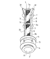
- FIG. 1 is a perspective view of a filter device according to an embodiment of the present invention.
- FIG. 2 is a perspective view of the filter device viewed from a different direction from FIG.
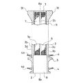
- FIG. 3 is a longitudinal sectional view of the filter device.
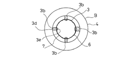
- FIG. 4 is a cross-sectional view of the filter device.
- FIG. 5 is a configuration diagram showing a use state of the filter device.
- FIG. 6 is a block diagram of a conventional example.
- FIG. 7 is a block diagram of a conventional example.
- the filter device according to this embodiment is inserted into a pipe P serving as a liquid flow path and filters the liquid flowing through the pipe P.
- a filter device has a main part B having a cylindrical shape, and causes the central axis Px of the pipe P to follow the cylindrical axis Bx of the main part B in the pipe P serving as a liquid flow path.
- the liquid flowing through the pipe P is filtered.
- the filter device is inserted into a pipe P serving as a radiator tank, and has a configuration suitable for filtering the liquid circulating through the radiator.
- Symbols Pa and Pb in the figure are communication portions between the pipe P and a core (not shown) of the radiator.
- liquid flows into the tube P through the upper communication portion Pa in FIG.
- the liquid flows out from the pipe P through the communication portion Pb on the side.
- the filter device is inserted into the pipe P from above in FIG. 5, and the space in the pipe P is vertically divided into a liquid-tight state by a flange portion 4 described later with the insertion.
- the inflow side communication portion Pa is located in the upper space thus divided, and the outflow side communication portion Pb is located in the lower space.
- the liquid that has flowed into the upper space from the radiator core side reaches the lower space through the filter device and then flows out again to the core side. In this process, the liquid is filtered by the filter device.
- the main part B closes one end 1 of the cylinder and opens the other end 2 of the cylinder.
- the filter device is inserted into the tube P with the other end 2 of the main body B at the top.
- a flange portion 4 which is elastically deformed during the insertion and is in close contact with the inner surface of the tube P to divide the space in the tube P into a liquid-tight state.
- the flange portion 4 is formed at two locations, a location close to the other end 2 of the cylinder of the main portion B and a location slightly above this. As a result, the liquid-tight state can be reliably produced. Further, in the illustrated example, a positioning flange 5 described later is provided between the two flange portions 4, 4.
- a widened portion 3f is formed in a longitudinal connecting piece 3b described later at the cylindrical one end portion 1 of the main portion B.
- the outer diameter of the main part B is slightly larger than the inner diameter of the pipe P in the flange part 4, and the main part B has a thickness substantially equal to the inner diameter of the pipe P at the location where the positioning flange part 5 and the widened part 3f are formed. Is configured to have.
- the outer diameter of the main part B is smaller than the inner diameter of the pipe P at a place other than the place where the flange part 4, the positioning flange part 5 and the widened part 3f are formed, and between the pipe P and the main part B at such a part. A liquid flow path is formed.
- Each of the two flange portions 4 and 4 protrudes outward from the main portion B, and circulates around the cylinder axis Bx of the main portion B without a break.
- the flange portion 4 is thin and has an elastic deformation characteristic. Further, the two flange portions 4, 4 are each projected in an inclined manner so as to approach the tube end portion 1 side of the main body portion B toward the protruding end 4 a. Accordingly, in this embodiment, when the filter device is inserted into the pipe P with the other end 2 of the cylinder B of the main body B as the head, the two flanges 4 and 4 are elasticized accordingly.
- the filter device which is easily deformed and, on the contrary, once inserted, is positioned stably in the pipe P because it does not easily come out of the pipe P due to the inclination of the flange portion 4.
- a positioning flange portion 5 that comes into contact with a contacted portion Pc provided on the tube P side at a position where insertion into the tube P is completed.
- the positioning flange 5 protrudes outward from the main part B and circulates around the cylinder axis Bx of the main part B without a break.
- the positioning flange 5 is thick and is configured not to be elastically deformed like the flange 4.
- the contacted portion Pc is formed at a location in the pipe P between the inflow side communication portion Pa and the outflow side communication portion Pb.
- the contacted part Pc is configured as a bulging part formed on the inner surface of the pipe P.
- the inner diameter of the tube P is smaller than the outer diameter of the positioning flange 5 at the position where the bulging portion is formed.
- the filter device is inserted into the tube P when the filter device is inserted into the tube P.
- the positioning flange 5 is not brought into contact with the contacted portion Pc unless the flange portion 4 positioned on the front side is elastically deformed and overcomes the contacted portion Pc. Unless this occurs, it is possible to make the insertion operator clearly recognize that the filter device has not been inserted into the pipe P up to a predetermined position.
- first passage portion 6 of the liquid covered with the filter medium 7 is provided in the cylinder side portion 3 between the cylinder one end portion 1 and the flange portion 4 in the main body portion B.
- the second passage 8 for the liquid is provided on the side of the other end 2 of the filter device with respect to the flange 4.
- the cylinder side part 3 between the cylinder one end part 1 of the main part B and the flange part 4 positioned on the cylinder one end part 1 side in the two flange parts 4 and 4 is the first part. It functions as the passing part 6.
- the cylindrical one end 1 of the main part B and the place where the flange part 4 is formed include a plurality of vertical connecting pieces 3b... 3b extending along the cylindrical axis Bx of the main part B and adjacent vertical connecting parts. It is connected by the cylinder side part structure 3a provided with the horizontal connection piece 3c between the pieces 3b and 3b, and between these connection pieces 3b and 3c is the 1st passage part 6.
- the cylinder one end 1 of the main part B is formed by a disk-like part having inner and outer surfaces orthogonal to the cylinder axis Bx of the main part B.
- the vertical connecting pieces 3b are provided on the outer peripheral portion of the main part B, and four vertical connecting pieces 3b are provided at substantially equal intervals between adjacent vertical connecting pieces 3b in the direction around the cylindrical axis Bx of the main part B. ing.
- Each of the longitudinal connecting pieces 3b has one end integrally connected to the disc-like portion 1a and the other end connected integrally to the formation portion of the flange portion 4.
- the horizontal connecting piece 3c is provided so as to extend between the adjacent vertical connecting pieces 3b at a position approximately in the middle of the longitudinal connecting piece 3b in the longitudinal direction.
- the lateral connecting piece 3c is provided so as to follow a virtual circular arc that the outer peripheral part of the main part B follows. Between the cylindrical one end 1 in the main part B and the place where the flange 4 is formed, between the cylindrical side part structure 3a having a hook shape formed by each of the connecting pieces and the connecting pieces 3b, 3c.
- the cylinder side part 3 is comprised by the filter medium 7 stuck.
- each connecting piece 3b, 3c is configured to have a long and narrow plate shape having both wide surfaces.
- Each connecting piece 3b, 3c has one end 3d of both ends 3d, 3e in the thickness direction facing outward of the main part B, and the other 3e of these end parts 3d, 3e is positioned inward of the main part B. It is arranged like that.
- the filter medium 7 has a sheet shape.
- the filter medium 7 is configured as a mesh.
- the filter medium 7 is selected according to the properties of the liquid to be filtered, and typically a nonwoven fabric or the like is also used.
- the main body B is formed by insert molding using a cylindrical filter medium 7 as an insert so that the filter medium 7 is positioned within the thickness of each connecting piece. That is, in the example shown in the figure, the filter medium 7 is configured by forming the sheet B-shaped filter medium 7 in a cylindrical shape as an insert in a mold and molding the main portion B with synthetic resin.
- the filter medium 7 can be firmly attached without any gap between the connecting pieces 3b and 3c, and a filter device having the above-described configuration can be easily manufactured.
- each vertical connecting piece 3b is configured to be wider so that the end 3d directed outward from the main body B is located outside the other part of the vertical connecting piece 3b.
- the filter device inserted into the pipe P is supported by the widened portions 3f of the four longitudinal connecting pieces 3b and the lower side of the filter device inserted into the pipe P by the positioning flange 5 It has come to be supported.
- the other end 2 of the cylinder with the main body B opened functions as the second passage 8.
- the filter device is inserted into the pipe P, and the inside of the pipe P is liquid-tightly divided by the flange portion 4.
- the first passage portion 6 is formed on the cylinder side portion 3 extending between the cylinder one end portion 1 of the main portion B and the flange portion 4, and the liquid is formed on the cylinder side portion 3 by the section.
- the entire filter medium 7 covering the first passage portion 6 can be effectively used for filtration, and the area of the first passage portion 6, that is, the aforementioned The filtration area of the filter medium 7 can be ensured as large as possible.
Landscapes
- Chemical & Material Sciences (AREA)
- Chemical Kinetics & Catalysis (AREA)
- Engineering & Computer Science (AREA)
- Physics & Mathematics (AREA)
- Thermal Sciences (AREA)
- Mechanical Engineering (AREA)
- General Engineering & Computer Science (AREA)
- Filtration Of Liquid (AREA)
- Filtering Materials (AREA)
- Lubrication Details And Ventilation Of Internal Combustion Engines (AREA)
- Separation Using Semi-Permeable Membranes (AREA)
Abstract
Description
前記主体部の筒一端部は閉塞されており、
前記主体部の筒両端部間には前記挿入において弾性変形して前記管の内面に密着してこの管内の空間を液密状態に区分する少なくとも一箇所のフランジ部が備えられており、
前記筒一端部とフランジ部との間の筒側部にはろ材により覆われた前記液体の第一通過部が設けられており、
前記フランジ部よりもフィルター装置の筒他端部側に前記液体の第二通過部が設けられているものとした。
Claims (6)
- 筒状をなす主体部を有すると共に、液体の流路となる管内にこの管の中心軸にこの主体部の筒軸を沿わせるように挿入されてこの管内を流れる液体の濾過をなすフィルター装置であって、
前記主体部の筒一端部は閉塞されており、
前記主体部の筒両端部間には前記挿入において弾性変形して前記管の内面に密着してこの管内の空間を液密状態に区分する少なくとも一箇所のフランジ部が備えられており、
前記筒一端部とフランジ部との間の筒側部にはろ材により覆われた前記液体の第一通過部が設けられており、
前記フランジ部よりもフィルター装置の筒他端部側に前記液体の第二通過部が設けられていることを特徴とするフィルター装置。 - フランジ部は、その突きだし端に向かうに連れて、主体部の筒一端部及び筒他端部のいずれか一方の側に近づくように、傾斜状に突き出されていることを特徴とする請求項1に記載のフィルター装置。
- 主体部の筒両端部間に、管内への挿入終了位置でこの管側に設けられた被当接部に当接される位置決め鍔部が備えられていることを特徴とする請求項1又は請求項2に記載のフィルター装置。
- フランジ部が、位置決め鍔部を挟んだ両側にそれぞれ備えられていることを特徴とする請求項3に記載のフィルター装置。
- 主体部の筒一端部とフランジ部の形成箇所とが、この主体部の筒軸に沿って延びる複数の縦連接片と、隣り合う縦連接片間に亘る横連接片とを備えてなる筒側部構成体により連接されており、これらの各連接片の間が第一通過部となっていることを特徴とする請求項1~請求項4のいずれか1項に記載のフィルター装置。
- ろ材が各連接片の肉厚内に位置されるように、筒状にしたろ材をインサートにしたインサート成形により主体部を成形してなることを特徴とする請求項5に記載のフィルター装置。
Priority Applications (3)
| Application Number | Priority Date | Filing Date | Title |
|---|---|---|---|
| CN201080066310.3A CN102858421B (zh) | 2010-04-22 | 2010-11-04 | 过滤装置 |
| MX2012012290A MX337652B (es) | 2010-04-22 | 2010-11-04 | Dispositivo de filtro. |
| US13/642,339 US9238187B2 (en) | 2010-04-22 | 2010-11-04 | Filter device |
Applications Claiming Priority (2)
| Application Number | Priority Date | Filing Date | Title |
|---|---|---|---|
| JP2010-098720 | 2010-04-22 | ||
| JP2010098720A JP5401395B2 (ja) | 2010-04-22 | 2010-04-22 | フィルター装置 |
Publications (1)
| Publication Number | Publication Date |
|---|---|
| WO2011132341A1 true WO2011132341A1 (ja) | 2011-10-27 |
Family
ID=44833889
Family Applications (1)
| Application Number | Title | Priority Date | Filing Date |
|---|---|---|---|
| PCT/JP2010/069629 Ceased WO2011132341A1 (ja) | 2010-04-22 | 2010-11-04 | フィルター装置 |
Country Status (5)
| Country | Link |
|---|---|
| US (1) | US9238187B2 (ja) |
| JP (1) | JP5401395B2 (ja) |
| CN (1) | CN102858421B (ja) |
| MX (1) | MX337652B (ja) |
| WO (1) | WO2011132341A1 (ja) |
Families Citing this family (9)
| Publication number | Priority date | Publication date | Assignee | Title |
|---|---|---|---|---|
| JP6701604B2 (ja) * | 2016-04-22 | 2020-05-27 | Toto株式会社 | 機能水生成機 |
| GB2560721B (en) * | 2017-03-21 | 2021-01-06 | Bamford Excavators Ltd | An oil filter assembly |
| KR101952310B1 (ko) * | 2017-04-06 | 2019-02-26 | 박경래 | 관내 삽입형 여과기 |
| WO2018231922A1 (en) | 2017-06-13 | 2018-12-20 | Elementis Specialties, Inc. | Coating system |
| DE102019121342B4 (de) * | 2018-08-15 | 2021-03-18 | Mann+Hummel Gmbh | Filterelement für den Einsatz als Partikelfilter in einem Kühlkreislauf eines elektrochemischen Energiewandlers und Verwendung des Filterelements in einer Anordnung mit einem elektrochemischen Energiewandler und einem Kühlkreislauf |
| USD967926S1 (en) * | 2019-03-21 | 2022-10-25 | Mahle International Gmbh | End plate for a filter element |
| CN112776781B (zh) * | 2019-11-08 | 2024-10-11 | 罗伯特·博世有限公司 | 用于车辆制动液贮存器的颈部过滤器 |
| US11825974B1 (en) * | 2020-03-01 | 2023-11-28 | Michael O. Murphy | Expandable strainer insert for bottles |
| JP7821151B2 (ja) * | 2023-12-19 | 2026-02-26 | 株式会社ディスコ | フィルターユニット |
Citations (8)
| Publication number | Priority date | Publication date | Assignee | Title |
|---|---|---|---|---|
| JPS481066U (ja) * | 1971-05-28 | 1973-01-09 | ||
| JPS489751Y1 (ja) * | 1970-06-25 | 1973-03-14 | ||
| JPS5639925B2 (ja) * | 1977-04-01 | 1981-09-17 | ||
| JPS586217A (ja) * | 1981-07-02 | 1983-01-13 | Terumo Corp | 濾過装置 |
| JPS631611U (ja) * | 1986-06-21 | 1988-01-07 | ||
| JPH0775706A (ja) * | 1993-06-16 | 1995-03-20 | Cosmo Koki Co Ltd | 給水管用夾雑物除去装置 |
| JP2000185207A (ja) * | 1998-06-16 | 2000-07-04 | Ford Global Technol Inc | 流体ライン用棒状パイプ・フィルタ― |
| JP2000342913A (ja) * | 1999-06-07 | 2000-12-12 | Komatsu Ltd | ラインフィルタ |
Family Cites Families (10)
| Publication number | Priority date | Publication date | Assignee | Title |
|---|---|---|---|---|
| DE2935916C3 (de) | 1979-09-06 | 1994-12-15 | Bosch Gmbh Robert | Steuervorrichtung für Antriebsanlagen von Kraftfahrzeugen |
| US4468217A (en) * | 1982-07-09 | 1984-08-28 | Kuzmick Kenneth M | Surgical suction tip with filter |
| JPS6349539U (ja) | 1986-09-18 | 1988-04-04 | ||
| JPH089751Y2 (ja) | 1989-05-31 | 1996-03-21 | 株式会社河合楽器製作所 | 鍵盤楽器の鍵盤押え |
| US5252204A (en) * | 1992-08-20 | 1993-10-12 | Manufacturers Components, Inc. | Unimold filter |
| JPH0775706B2 (ja) * | 1992-10-03 | 1995-08-16 | 啓行 中川 | 濾過装置 |
| US5393425A (en) * | 1993-11-16 | 1995-02-28 | Cobb, Jr.; Clois R. | Irrigation system lateral pickup pipe strainer |
| JPH081066A (ja) * | 1994-06-23 | 1996-01-09 | Tatsumo Kk | 回転式薬液処理装置のバキュームシール構造 |
| US6231762B1 (en) * | 2000-01-31 | 2001-05-15 | Bowco Industries Inc. | Filtration system for septic system |
| US6849179B1 (en) * | 2003-06-17 | 2005-02-01 | Hydro-Gear Limited Partnership | Internal filter |
-
2010
- 2010-04-22 JP JP2010098720A patent/JP5401395B2/ja active Active
- 2010-11-04 MX MX2012012290A patent/MX337652B/es active IP Right Grant
- 2010-11-04 WO PCT/JP2010/069629 patent/WO2011132341A1/ja not_active Ceased
- 2010-11-04 US US13/642,339 patent/US9238187B2/en active Active
- 2010-11-04 CN CN201080066310.3A patent/CN102858421B/zh active Active
Patent Citations (8)
| Publication number | Priority date | Publication date | Assignee | Title |
|---|---|---|---|---|
| JPS489751Y1 (ja) * | 1970-06-25 | 1973-03-14 | ||
| JPS481066U (ja) * | 1971-05-28 | 1973-01-09 | ||
| JPS5639925B2 (ja) * | 1977-04-01 | 1981-09-17 | ||
| JPS586217A (ja) * | 1981-07-02 | 1983-01-13 | Terumo Corp | 濾過装置 |
| JPS631611U (ja) * | 1986-06-21 | 1988-01-07 | ||
| JPH0775706A (ja) * | 1993-06-16 | 1995-03-20 | Cosmo Koki Co Ltd | 給水管用夾雑物除去装置 |
| JP2000185207A (ja) * | 1998-06-16 | 2000-07-04 | Ford Global Technol Inc | 流体ライン用棒状パイプ・フィルタ― |
| JP2000342913A (ja) * | 1999-06-07 | 2000-12-12 | Komatsu Ltd | ラインフィルタ |
Also Published As
| Publication number | Publication date |
|---|---|
| US20130206679A1 (en) | 2013-08-15 |
| JP5401395B2 (ja) | 2014-01-29 |
| MX337652B (es) | 2016-03-14 |
| JP2011224507A (ja) | 2011-11-10 |
| CN102858421A (zh) | 2013-01-02 |
| MX2012012290A (es) | 2012-11-23 |
| US9238187B2 (en) | 2016-01-19 |
| CN102858421B (zh) | 2015-09-30 |
Similar Documents
| Publication | Publication Date | Title |
|---|---|---|
| JP5401395B2 (ja) | フィルター装置 | |
| US10272373B2 (en) | Return filter | |
| JP6302338B2 (ja) | オイルストレーナ | |
| US20190143251A1 (en) | Filtering assembly comprising a filter cartridge | |
| JP5834858B2 (ja) | 流体フィルタ | |
| US20170361249A1 (en) | Filter center tube with standpipe and flow fins | |
| US10702808B2 (en) | Filter device and filtration device | |
| US20180229157A1 (en) | Return filter | |
| KR101358848B1 (ko) | 두 개의 수평 플레이트 필터를 구비한 쐐기형 필터 소자 | |
| JP6410578B2 (ja) | オイルストレーナ | |
| DE102014006117A1 (de) | Filterelement, insbesondere zur Gasfiltration | |
| JP6253100B2 (ja) | リザーバタンク | |
| JP6602680B2 (ja) | オイルストレーナ | |
| JP2019183850A (ja) | オイルストレーナ | |
| KR101566110B1 (ko) | 자동차용 에어클리너 어셈블리 | |
| CN208626747U (zh) | 一种便于更换滤芯的水用过滤器 | |
| JP6199157B2 (ja) | オイルストレーナ | |
| JP6232236B2 (ja) | オイルストレーナ | |
| JP2017133398A (ja) | オイルストレーナ | |
| CN205403271U (zh) | 一种冰箱过滤器的滤芯 | |
| JP3187841U (ja) | オイルフィルタ | |
| JP6709112B2 (ja) | オイルストレーナ | |
| KR200468891Y1 (ko) | 엘리먼트 가이드 | |
| JP6487462B2 (ja) | 脱着式フィルタ容器およびそれを用いた濾過装置 | |
| BR102014008040A2 (pt) | sistema de filtragem e cartucho de filtro |
Legal Events
| Date | Code | Title | Description |
|---|---|---|---|
| WWE | Wipo information: entry into national phase |
Ref document number: 201080066310.3 Country of ref document: CN |
|
| 121 | Ep: the epo has been informed by wipo that ep was designated in this application |
Ref document number: 10850282 Country of ref document: EP Kind code of ref document: A1 |
|
| NENP | Non-entry into the national phase |
Ref country code: DE |
|
| WWE | Wipo information: entry into national phase |
Ref document number: 1201005530 Country of ref document: TH Ref document number: MX/A/2012/012290 Country of ref document: MX |
|
| WWE | Wipo information: entry into national phase |
Ref document number: 13642339 Country of ref document: US |
|
| 122 | Ep: pct application non-entry in european phase |
Ref document number: 10850282 Country of ref document: EP Kind code of ref document: A1 |