WO2011132229A1 - 燃料電池システム及び燃料電池の発電効率の低下を抑制する方法 - Google Patents
燃料電池システム及び燃料電池の発電効率の低下を抑制する方法 Download PDFInfo
- Publication number
- WO2011132229A1 WO2011132229A1 PCT/JP2010/002927 JP2010002927W WO2011132229A1 WO 2011132229 A1 WO2011132229 A1 WO 2011132229A1 JP 2010002927 W JP2010002927 W JP 2010002927W WO 2011132229 A1 WO2011132229 A1 WO 2011132229A1
- Authority
- WO
- WIPO (PCT)
- Prior art keywords
- fuel cell
- heat medium
- temperature
- circulation circuit
- heater
- Prior art date
- Legal status (The legal status is an assumption and is not a legal conclusion. Google has not performed a legal analysis and makes no representation as to the accuracy of the status listed.)
- Ceased
Links
Images



Classifications
-
- H—ELECTRICITY
- H01—ELECTRIC ELEMENTS
- H01M—PROCESSES OR MEANS, e.g. BATTERIES, FOR THE DIRECT CONVERSION OF CHEMICAL ENERGY INTO ELECTRICAL ENERGY
- H01M8/00—Fuel cells; Manufacture thereof
- H01M8/04—Auxiliary arrangements, e.g. for control of pressure or for circulation of fluids
- H01M8/04007—Auxiliary arrangements, e.g. for control of pressure or for circulation of fluids related to heat exchange
- H01M8/04029—Heat exchange using liquids
-
- H—ELECTRICITY
- H01—ELECTRIC ELEMENTS
- H01M—PROCESSES OR MEANS, e.g. BATTERIES, FOR THE DIRECT CONVERSION OF CHEMICAL ENERGY INTO ELECTRICAL ENERGY
- H01M8/00—Fuel cells; Manufacture thereof
- H01M8/04—Auxiliary arrangements, e.g. for control of pressure or for circulation of fluids
- H01M8/04007—Auxiliary arrangements, e.g. for control of pressure or for circulation of fluids related to heat exchange
- H01M8/04037—Electrical heating
-
- H—ELECTRICITY
- H01—ELECTRIC ELEMENTS
- H01M—PROCESSES OR MEANS, e.g. BATTERIES, FOR THE DIRECT CONVERSION OF CHEMICAL ENERGY INTO ELECTRICAL ENERGY
- H01M8/00—Fuel cells; Manufacture thereof
- H01M8/04—Auxiliary arrangements, e.g. for control of pressure or for circulation of fluids
- H01M8/04298—Processes for controlling fuel cells or fuel cell systems
- H01M8/04313—Processes for controlling fuel cells or fuel cell systems characterised by the detection or assessment of variables; characterised by the detection or assessment of failure or abnormal function
- H01M8/0432—Temperature; Ambient temperature
- H01M8/04373—Temperature; Ambient temperature of auxiliary devices, e.g. reformers, compressors, burners
-
- H—ELECTRICITY
- H01—ELECTRIC ELEMENTS
- H01M—PROCESSES OR MEANS, e.g. BATTERIES, FOR THE DIRECT CONVERSION OF CHEMICAL ENERGY INTO ELECTRICAL ENERGY
- H01M8/00—Fuel cells; Manufacture thereof
- H01M8/04—Auxiliary arrangements, e.g. for control of pressure or for circulation of fluids
- H01M8/04298—Processes for controlling fuel cells or fuel cell systems
- H01M8/04694—Processes for controlling fuel cells or fuel cell systems characterised by variables to be controlled
- H01M8/04701—Temperature
- H01M8/04731—Temperature of other components of a fuel cell or fuel cell stacks
-
- H—ELECTRICITY
- H01—ELECTRIC ELEMENTS
- H01M—PROCESSES OR MEANS, e.g. BATTERIES, FOR THE DIRECT CONVERSION OF CHEMICAL ENERGY INTO ELECTRICAL ENERGY
- H01M8/00—Fuel cells; Manufacture thereof
- H01M8/04—Auxiliary arrangements, e.g. for control of pressure or for circulation of fluids
- H01M8/04298—Processes for controlling fuel cells or fuel cell systems
- H01M8/04694—Processes for controlling fuel cells or fuel cell systems characterised by variables to be controlled
- H01M8/04701—Temperature
- H01M8/04738—Temperature of auxiliary devices, e.g. reformer, compressor, burner
-
- H—ELECTRICITY
- H01—ELECTRIC ELEMENTS
- H01M—PROCESSES OR MEANS, e.g. BATTERIES, FOR THE DIRECT CONVERSION OF CHEMICAL ENERGY INTO ELECTRICAL ENERGY
- H01M2250/00—Fuel cells for particular applications; Specific features of fuel cell system
- H01M2250/20—Fuel cells in motive systems, e.g. vehicle, ship, plane
-
- Y—GENERAL TAGGING OF NEW TECHNOLOGICAL DEVELOPMENTS; GENERAL TAGGING OF CROSS-SECTIONAL TECHNOLOGIES SPANNING OVER SEVERAL SECTIONS OF THE IPC; TECHNICAL SUBJECTS COVERED BY FORMER USPC CROSS-REFERENCE ART COLLECTIONS [XRACs] AND DIGESTS
- Y02—TECHNOLOGIES OR APPLICATIONS FOR MITIGATION OR ADAPTATION AGAINST CLIMATE CHANGE
- Y02E—REDUCTION OF GREENHOUSE GAS [GHG] EMISSIONS, RELATED TO ENERGY GENERATION, TRANSMISSION OR DISTRIBUTION
- Y02E60/00—Enabling technologies; Technologies with a potential or indirect contribution to GHG emissions mitigation
- Y02E60/30—Hydrogen technology
- Y02E60/50—Fuel cells
-
- Y—GENERAL TAGGING OF NEW TECHNOLOGICAL DEVELOPMENTS; GENERAL TAGGING OF CROSS-SECTIONAL TECHNOLOGIES SPANNING OVER SEVERAL SECTIONS OF THE IPC; TECHNICAL SUBJECTS COVERED BY FORMER USPC CROSS-REFERENCE ART COLLECTIONS [XRACs] AND DIGESTS
- Y02—TECHNOLOGIES OR APPLICATIONS FOR MITIGATION OR ADAPTATION AGAINST CLIMATE CHANGE
- Y02T—CLIMATE CHANGE MITIGATION TECHNOLOGIES RELATED TO TRANSPORTATION
- Y02T90/00—Enabling technologies or technologies with a potential or indirect contribution to GHG emissions mitigation
- Y02T90/40—Application of hydrogen technology to transportation, e.g. using fuel cells
Definitions
- the present invention relates to a fuel cell system that uses waste heat of a fuel cell.
- a technology that uses waste heat of the fuel cell as a heat source for temperature adjustment in the passenger compartment is known.
- a heat medium such as cooling water flowing in the fuel cell is supplied to a heater core for air conditioning, and air whose temperature is adjusted by the heater core is supplied into the vehicle interior (see, for example, Patent Document 1).
- this technique has a problem in that the power generation efficiency of the fuel cell is lowered because the temperature of the heat medium supplied to the fuel cell varies as it passes through the heater core.
- Such a problem is not limited to a vehicle equipped with a fuel cell, and is a problem common to all fuel cell systems equipped with a fuel cell.
- the present invention has been made to solve the above-described conventional problems, and provides a technique capable of suppressing a decrease in power generation efficiency of a fuel cell in a fuel cell system that uses waste heat of the fuel cell. For the purpose.
- the present invention can take the following forms or application examples in order to solve at least a part of the problems described above.
- a fuel cell system including a fuel cell, a heater core used in a heating device, a first circulation circuit that circulates a heat medium through the fuel cell, and a first that circulates the heat medium through the heater core.
- 2 circulation circuits a connection flow path for connecting the first circulation circuit and the second circulation circuit, and circulating a heat medium between the first circulation circuit and the second circulation circuit;
- a first heat medium that is disposed on the second circulation circuit and downstream of the heater core and adjusts the temperature of the heat medium after flowing out of the heater core and before flowing into the fuel cell.
- a fuel cell system comprising a temperature adjustment unit.
- the first temperature adjustment unit adjusts the temperature of the heat medium before flowing into the fuel cell, it is possible to suppress a decrease in power generation efficiency of the fuel cell.
- Application Example 2 The fuel cell system according to Application Example 1, further including a first temperature sensor that is disposed upstream of the fuel cell and measures a temperature of a heat medium before flowing into the fuel cell, and the first temperature sensor. And a control unit that controls the first temperature adjustment unit based on the temperature of the heat medium measured by the temperature sensor.
- the control unit controls the first temperature adjusting unit based on the temperature of the heat medium before flowing into the fuel cell, the temperature of the heat medium flowing into the fuel cell is controlled. It can be adjusted more accurately.
- Application Example 3 The fuel cell system according to Application Example 1 or 2, further including a heat medium that is disposed on the second circulation circuit and upstream of the heater core and flows out of the fuel cell.
- a fuel cell system including a second temperature adjusting unit that adjusts the temperature of the heat medium before flowing into the heater core.
- the second temperature adjustment unit adjusts the temperature of the heat medium before flowing into the heater core, the temperature of the heat medium flowing into the heater core is desired to be required for the heater core. Temperature.
- Application Example 4 The fuel cell system according to Application Example 3, further including a second temperature sensor that is arranged on the upstream side of the heater core and measures the temperature of the heat medium before flowing into the heater core, and the control unit includes: A fuel cell system that controls the second temperature adjustment unit based on the temperature of the heat medium measured by the second temperature sensor.
- the control unit controls the second temperature adjusting unit based on the temperature of the heat medium before flowing into the heater core, the temperature of the heat medium flowing into the heater core is more accurately determined. Can be adjusted.
- the first temperature adjustment unit is a first electric heater
- the second temperature adjustment unit is a second electric heater
- the control unit is The heater capacity of the first electric heater is feedback-controlled based on the target temperature of the heat medium allowed in the fuel cell, and the second based on the target temperature of the heat medium required from the heating device.
- a fuel cell system that feedback-controls the heater capacity of an electric heater.
- the temperature of the heat medium can be made to follow the target temperature.
- a method for suppressing a decrease in power generation efficiency of a fuel cell wherein the first circulation circuit is used to circulate a heat medium passing through the fuel cell, and the second circulation circuit is used for a heating device. Circulating the heat medium passing through the heater core, connecting the first circulation circuit and the second circulation circuit, and between the first circulation circuit and the second circulation circuit And a step of adjusting the temperature of the heat medium after flowing out of the heater core and before flowing into the fuel cell.
- the present invention can be realized in various modes.
- the present invention can be realized in the form of a method and apparatus for suppressing a decrease in power generation efficiency of a fuel cell, an integrated circuit for realizing the function of the method or apparatus, a computer program, a recording medium recording the computer program, and the like. it can.
- FIG. 1 is an explanatory diagram showing a configuration of a fuel cell system 10 and its periphery. Explanatory drawing which shows the state which the heat medium which flowed out from the 2nd heat medium flow path 62 by controlling the 1st three-way valve 33 does not flow into the 3rd heat medium flow path 63 but flows into all the 4th heat medium flow paths 64 It is. It is explanatory drawing which shows the state by which the 1st circulation circuit C1 and the 2nd circulation circuit C2 were physically connected by controlling the 2nd three-way valve 58.
- FIG. It is a flowchart which shows the electric heater control process at the time of a cooperation state.
- FIG. 1 is an explanatory diagram showing a schematic configuration around a front portion 1f of a vehicle 1 on which a fuel cell system 10 as an embodiment of the present invention is mounted.
- a fuel cell system 10 mainly includes a fuel cell stack 20 and an air conditioner 50.
- the front portion 1f is further provided with a drive motor 5 that generates propulsive force of the vehicle 1 by the electric power generated in the fuel cell stack 20, a gear 7 that transmits torque generated by the drive motor 5 to the axle, and the like.
- the headlight 2, the air conditioner 50, and the air compressor 3 are also driven by the electric power generated in the fuel cell stack 20.
- the air conditioner 50 controls the temperature inside the passenger compartment 1r.
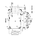
- FIG. 2 is an explanatory diagram showing the configuration of the fuel cell system 10 and its surroundings.
- the fuel cell system 10 is configured around the fuel cell stack 20 and the control unit 100, and includes a first circulation circuit C1 and a second circulation circuit C2 for performing thermal movement of the system.
- the thick solid-line arrow in a figure has shown the flow of the heat medium.
- the first circulation circuit C1 is a circuit that mainly carries a heat medium that has absorbed heat generated in the fuel cell stack 20 to the radiator 30 and circulates the heat medium cooled by the radiator 30 to the fuel cell stack 20.
- This circulation is performed by the pump 32, and the heat medium pushed out by the pump 32 is the first heat medium flow path 61 provided with the pump 32 ⁇ the medium flow path in the fuel cell 20 ⁇ the second heat medium flow. It flows in the order of the passage 62 ⁇ the third heat medium passage 63 ⁇ the radiator 30 ⁇ the first three-way valve 33 and circulates to the pump 32.
- the radiator 30 is provided with a fourth heat medium flow path 64 that bypasses the fourth heat medium flow path 64.
- the fourth heat medium flow path 64 is a point from the second heat medium flow path 62 to the third heat medium flow path 63.
- the first three-way valve 33 joins the first heat medium flow path 61.
- the two ports on the input side of the first three-way valve 33 are connected to the fourth heat medium flow path 64 and the outlet pipe of the radiator 30, respectively, and the port on the output side of the first three-way valve 33 is connected to the first heat medium flow. It is connected to the path 61.
- the first three-way valve 33 has two switching positions a and b, and performs an operation of switching ports in accordance with a signal from the control unit 100. In the position a shown in FIG. 2, the first three-way valve 33 connects the outlet pipe of the radiator 30 and the first heat medium flow path 61 and closes the fourth heat medium flow path 64 side. The passing heat medium circulates through the first circulation circuit C1. On the other hand, when the first three-way valve 33 is switched to the operating position b from this state, the connection relation of the flow paths is reversed, and the heat medium passing through the fourth heat medium flow path 64 passes through the first circulation circuit C1. Circulate.
- the second circulation circuit C2 is a circulation path that conveys the amount of heat necessary for air conditioning to the air conditioner 50 using a heat medium.
- This circulation is performed by the second pump 54, and the heat medium pushed out by the second pump 54 is the sixth heat medium flow channel 66 provided with the second pump 54 ⁇ the heater core 51 ⁇ the seventh heat medium flow. It flows in the order of the passage 67 ⁇ the eighth heat medium passage 68 ⁇ the second three-way valve 58 and circulates in the second pump 54.
- a second electric heater 57 is provided in the flow path from the second pump 54 to the heater core 51, and a first electric heater 55 is provided in the flow path from the heater core 51 to the seventh heat medium flow path 67. ing.
- the heater core 51 is a heating heat exchanger used in the air conditioner 50.
- the second circulation circuit C2 is connected to the first circulation circuit C1 at two locations, and the heat medium can be shared by both circulation circuits C1 and C2.
- the fifth heat medium flow path 65 branched from the fuel cell stack 20 to the second heat medium flow path 62 is connected to the second three-way valve 58, whereby the second three-way valve 58 Depending on the open / close state, a part of the heat medium circulating in the first circulation circuit C1 can flow into the second circulation circuit C2.
- the heat medium circulated through the second circulation circuit C2 branches at a point where the seventh heat medium flow path 67 reaches the eighth heat medium flow path 68 and is connected to the second heat medium flow path 62 of the first circulation circuit C1.
- the ninth heat medium passage 69 returns to the first circulation circuit C1.
- the two ports on the input side of the second three-way valve 58 are connected to the fifth heat medium flow path 65 and the eighth heat medium flow path 68, respectively, and the port on the output side of the second three-way valve 58 is the sixth heat medium flow path.
- the medium channel 66 is connected.
- the second three-way valve 58 has two switching positions a and b, and performs the operation of switching the port by a signal from the control unit 100 as in the first three-way valve 33. In the position a shown in FIG. 2, the second three-way valve 58 connects the eighth heat medium flow path 68 and the sixth heat medium flow path 66 and closes the fifth heat medium flow path 65 side.
- the medium circulates through the second circulation circuit C1. That is, in the example of FIG.
- the heat medium circulates independently in the first circulation circuit C1 and the second circulation circuit C2.
- a state in which the heat medium circulates independently in the first circulation circuit C1 and the second circulation circuit C2 in this way is referred to as an “independent state”.
- the connection relation of the flow paths is reversed, and a part of the heat medium circulating in the first circulation circuit C1 becomes the second circulation circuit C2.
- the air conditioner 50 is passed through and returns to the first circulation circuit C1.
- this state is referred to as a “cooperation state”.
- the fuel cell stack 20 is a solid polymer electrolyte fuel cell, and has a configuration in which a plurality of single cells each having a membrane electrode assembly (MEA) are stacked.
- Hydrogen gas as fuel gas is supplied to the fuel cell stack 20 from a hydrogen gas tank (not shown) via a fuel gas flow path 22.
- air as an oxidant gas is supplied to the fuel cell stack 20 through the oxidant gas flow path 24 by the air compressor 3 (FIG. 1).
- the fuel cell stack 20 is supplied with a heat medium as a cooling medium, and each single cell whose temperature is increased due to power generation is cooled by the heat medium.
- an antifreeze solution in which ethylene glycol or the like is added to water is used as a heat medium, but any cooling water such as pure water can be used instead of the antifreeze solution. Further, a gas such as carbon dioxide may be used as the heat medium instead of the cooling water.
- a load 40 is electrically connected to the fuel cell stack 20 via an inverter (not shown), and electric power generated by an electrochemical reaction in the fuel cell stack 20 is supplied to the load 40.
- the load 40 is a set of various loads. As described above, each load includes the headlight 2, the air compressor 3, the drive motor 5, two electric fans 31, 52 described later, and the first electric It means the heater 55, the second electric heater 57, the two pumps 32, 54, and the like. Furthermore, all the electric devices mounted on the vehicle 1 such as a navigation device and an audio device (not shown) may correspond to each load of the load 40.
- radiator fan 31 In the vicinity of the radiator 30 disposed in the third heat medium flow path 63, an electric fan (hereinafter referred to as "radiator fan") 31 is disposed.
- the radiator 30 cools the heat medium sent from the fuel cell stack 20 via the second heat medium flow path 62 by the wind from the radiator fan 31, and releases the heat of the heat medium to the outside of the vehicle.
- the fourth heat medium flow path 64 is a bypass circuit that bypasses the radiator 30 and connects the second heat medium flow path 62 and the first heat medium flow path 61. For this reason, the heat dissipation amount of the heat medium passing through the fourth heat medium flow path 64 is smaller than the heat dissipation amount of the heat medium passing through the third heat medium flow path 63.
- the first electric heater 55 is disposed on the downstream side of the heater core 51 as described above, and can heat the heat medium flowing through the seventh heat medium flow path 67.
- the first electric heater 55 is configured such that, in the linked state, the temperature of the heat medium flowing through the first heat medium flow path 61 (that is, the temperature of the heat medium flowing into the fuel cell stack 20) is the fuel cell stack.
- the temperature is lower than the allowable temperature range of the heat medium 20
- the heat medium flowing through the seventh heat medium flow path 67 is warmed.
- the allowable temperature range for example, 70 ° C. to 75 ° C.
- the second electric heater 57 is arranged on the upstream side of the heater core 51 as described above, and can heat the heat medium flowing through the sixth heat medium flow channel 66. Specifically, the second electric heater 57 warms the heat medium when the temperature of the heat medium flowing into the heater core 51 is lower than the temperature of the heat medium required for the heater core 51. By so doing, the heat medium flowing into the heater core 51 has a desired temperature, so the air conditioner 50 can perform the desired heating. Details of the control of the first electric heater 55 and the second electric heater 57 will be described later.
- the air conditioner 50 includes the aforementioned heater core 51, an electric fan (hereinafter referred to as “blower fan”) 52, and a casing 53.
- the heater core 51 is a heat exchanger for heating, and is heated by the heat of the heat medium flowing through the second circulation circuit C2.
- the blower fan 52 sends air heated by the heater core 51 toward the outside of the casing 53 (inside the passenger compartment 1r shown in FIG. 1) by sending air to the heater core 51.
- the air conditioner 50 is connected to various air outlets (ventilator, foot, defroster, etc.) via ducts (not shown), and sends warm air from these air outlets.
- the operation panel 70 includes various switches that can be operated by passengers. As various switches, an air conditioner (air conditioner) switch, a room temperature setting switch, and the like are applicable.
- an air conditioner (air conditioner) switch As various switches, an air conditioner (air conditioner) switch, a room temperature setting switch, and the like are applicable.
- the control unit 100 mainly includes a CPU (Central Processing Unit) 101, a memory 102, and an input / output circuit 103.
- the input / output circuit 103 is connected to various actuators, various sensors, and the operation panel 70 via signal lines (not shown).
- the memory 102 stores a computer program (not shown) mainly for controlling the fuel cell system 10.
- the CPU 101 functions as the heater control unit 110 and the circuit switching control unit 120 by executing this computer program.
- the heater control unit 110 and the circuit switching control unit 120 drive various actuators based on detection values of various sensors, output signals of the operation panel 70, and the like to control the temperature in the passenger compartment 1r.
- the memory 102 stores in advance a first heater capacity increase / decrease map MP1 and a second heater capacity increase / decrease map MP2 that are used by the heater control unit 110. These will be described later.
- Various actuators include two electric fans 31, 52, two electric heaters 55, 57, two pumps 32, 54, two three-way valves 33, 58, and the like.
- Various sensors include various temperature sensors, voltage sensors (not shown), current sensors (not shown), and the like.
- the first temperature sensor 34 provided upstream of the heat medium inlet of the fuel cell stack 20
- the second temperature sensor 56 provided upstream of the heat medium inlet of the heater core 51
- the in-vehicle temperature sensor (Not shown), an outside temperature sensor (not shown), a solar radiation amount sensor (not shown), etc. are provided as various temperature sensors.
- the first temperature sensor 34 measures the temperature T1 of the heat medium flowing into the fuel cell stack 20.
- the second temperature sensor 56 measures the temperature T2 of the heat medium flowing into the heater core 51.
- the heat medium flowing out from the second heat medium flow path 62 does not flow into the third heat medium flow path 63 but all flows into the fourth heat medium flow path 64.
- first independent state the state in which the fourth heat medium flow path 64 is closed and the third heat medium flow path 63 is open
- second independent state there is a state where the third heat medium flow path 63 is closed and the fourth heat medium flow path 64 is open. That is, the independent state includes a first independent state (FIG. 2) in which the radiator 30 is used and a second independent state (FIG. 3) in which the radiator 30 is not used.
- FIG. 4 is an explanatory diagram showing a state in which the first circulation circuit C1 and the second circulation circuit C2 are physically connected by controlling the second three-way valve 58.
- This state is the cooperation state described above, and the heat medium is exchanged between the first circulation circuit C1 and the second circulation circuit C2.
- the second three-way valve 58 connects the sixth heat medium flow channel 66 and the fifth heat medium flow channel 65, and connects the sixth heat medium flow channel 66 and the eighth heat medium flow channel 68.
- the heat medium is exchanged between the first circulation circuit C1 and the second circulation circuit C2.
- heating by the heater core 51 can be performed using the waste heat of the fuel cell stack 20.
- the first three-way valve 33 is controlled so that the heat medium flowing out from the second heat medium flow path 62 flows into the third heat medium flow path 63 in the first circulation circuit C1. However, all are configured to flow into the fourth heat medium flow path 64. The reason for this is to prevent the heat medium flowing into the heater core 51 from being cooled by the radiator 30.
- the circuit switching control unit 120 (FIG. 2) adjusts the first three-way valve 33 and the second three-way valve 58 so that the heat medium circuit in the fuel cell system 10 is in the first independent state and the second independent state described above. , And any one of the linked states.
- the circuit switching control unit 120 can execute various modes of circuit switching control. Specifically, for example, when the temperature of the fuel cell stack 20 is higher than a predetermined value and there is a request from the air conditioner 50, the waste heat of the fuel cell stack 20 can be used for heating the heater core 51. Therefore, the circuit switching control unit 120 switches the fuel cell system 10 to the linked state (FIG. 4).
- a circuit switching control unit is used to cool the heat medium passing through the fuel cell stack 20 by the radiator 30. 120 switches the fuel cell system 10 to the first independent state (FIG. 2). When the temperature of the fuel cell stack 20 falls below a predetermined value, the circuit switching control unit 120 switches the fuel cell system 10 to the second independent state (FIG. 3).
- the heater control unit 110 performs feedback control of the heater capacity of the second electric heater 57 so that the temperature T2 of the heat medium measured by the second temperature sensor 56 becomes the required temperature Two requested by the heater core 51. . Details of the processing will be described below.
- FIG. 5 is a flowchart showing an example of the electric heater control process in the linked state. This electric heater control process is executed by the heater control unit 110 of the control unit 100, and is repeatedly executed every predetermined time.
- step S110 the first temperature sensor 34 measures the temperature T1 of the heat medium before flowing into the fuel cell stack 20, and the second temperature sensor 56 measures the temperature T2 of the heat medium before flowing into the heater core 51. To do.
- step S120 the heater control unit 110 sets an allowable temperature range (TL ° C. to TH ° C.) allowed for the heat medium flowing into the fuel cell stack 20.
- This allowable temperature range is set in order to suppress deterioration of the fuel cell stack 20 or to realize high-efficiency operation of the fuel cell stack 20.
- the heater control unit 110 sets a required temperature Two that is a temperature required for the heat medium flowing into the heater core 51 based on the target blowing temperature Tao input from the air conditioner 50.
- the target blowing temperature Tao is a target value of the temperature of air blown out from the air conditioner 50, and is calculated in a separate routine by a known method.
- the target blowing temperature Tao is obtained in consideration of the temperature outside the vehicle, the amount of solar radiation, and the like in the difference between the in-vehicle temperature and the temperature set by the user.
- the heater control unit 110 searches the first heater capacity increase / decrease map MP1 using the calculated Ean and EDOTa as keys, and determines the increase / decrease amount dW1 of the heater capacity of the first electric heater 55.
- First heater capacity controller map MP1 is a two-input table, increment and decrement dW1 heater capacity corresponding to Ea n and EDOTa is preset.
- the heater capacity increase / decrease amount dW1 in the first heater capacity increase / decrease map MP1 is set based on experimental data performed in advance, but is set based on simulation results or results of predetermined arithmetic processing. It is also good to do. Specifically, for example, heating capacity increment or decrement dW1 is set to be larger as Ea n is large.
- heating capacity increment or decrement dW1 also Ea n are the same value, a value corresponding to EDOTa is set.
- the second heater capacity increase / decrease map MP2 used in step S140 described later has the same tendency as the first heater capacity increase / decrease map MP1.
- step S140 the heater control unit 110 performs feedback control of the heater capacity of the second electric heater 57 so that the temperature T2 becomes the required temperature Two.
- the heater control unit 110 calculates Eb n and EDOTb based on the following equations.
- Eb n Two ⁇ T2
- EDOTb Eb n ⁇ Eb n ⁇ 1
- Eb n is the difference between the required temperature Two and the temperature T2 calculated in this routine
- Eb n-1 is the required temperature Two calculated when the previous routine is executed. It is a difference from the temperature T2.
- Eb n calculated in the current routine becomes Eb n-1 in the next routine.
- the heater control unit 110 searches the second heater capacity increase / decrease map MP2 using the calculated Eb n and EDOTb as keys, and determines the increase / decrease amount dW2 of the heater capacity of the second electric heater 57.
- step S150 the heater control unit 110 controls the heater capacities of the first and second electric heaters 55 and 57 based on the calculated heater capacity increases and decreases dW1 and dW2.
- step S150 ends, the heater control unit 110 starts the process of step S110 again after a predetermined time has elapsed.
- the first independent state, the second independent state, and the cooperation state can be switched, so that the waste heat of the fuel cell stack 20 is effectively used. be able to.
- the heat medium whose temperature has been lowered by passing through the heater core 51 can be warmed by the first electric heater 55, so that the temperature of the heat medium supplied to the fuel cell stack 20 is set to the fuel cell stack 20. It is possible to be within the allowable temperature range. For this reason, it becomes possible to suppress the fall of the power generation efficiency of the fuel cell stack 20.
- the heat medium supplied to the heater core 51 can be heated by the second electric heater 57, the temperature of the heat medium is set to a temperature required for the heater core 51. can do.
- the heat medium supplied to the heater core 51 may be warmed using the two electric heaters 55 and 57. By so doing, it is possible to raise the temperature of the heat medium faster than when only the second electric heater 57 is used.
- the 1st temperature sensor 34 was arrange
- the first temperature sensor 34 may be disposed upstream of the fuel cell and at a position where the temperature of the heat medium before flowing into the fuel cell system 10 can be measured.
- the first temperature sensor 34 is located downstream of the connection point with the ninth heat medium flow channel 69 in the fourth heat medium flow channel 64, the ninth heat medium flow channel 69, and the second heat medium flow channel 62. It is possible to arrange them.
- the 2nd temperature sensor 56 was arrange
- the second temperature sensor 56 can be disposed on the fifth heat medium flow path 65 or the second heat medium flow path 62 on the upstream side of the connection portion with the fifth heat medium flow path 65 or the like. is there.
- the heat medium is heated by the first electric heater 55 to adjust the temperature of the heat medium supplied to the fuel cell system 10, but in addition to this, the temperature of the heat medium is decreased.
- a mechanism for example, a fan or the like
- a mechanism for reducing the temperature of the heat medium supplied to the heater core 51 may be provided to adjust the temperature of the heat medium supplied to the heater core 51.
- feedback control of the heater capacities of the two electric heaters 55 and 57 is performed using the two types of heater capacity increase / decrease maps MP1 and MP2. It is good also as performing feedback control of the heater capacity
- the fuel cell system 10 is used by being mounted on an electric vehicle. Instead, the fuel cell system 10 is applied to various vehicles such as a hybrid vehicle and a train, or a household power supply system provided with an air conditioning mechanism. It can also be applied.
- a polymer electrolyte fuel cell is used as the fuel cell stack 20, but various fuel cells such as a phosphoric acid fuel cell, a molten carbonate fuel cell, and a solid oxide fuel cell may be used. it can.
Landscapes
- Life Sciences & Earth Sciences (AREA)
- Engineering & Computer Science (AREA)
- Manufacturing & Machinery (AREA)
- Sustainable Development (AREA)
- Sustainable Energy (AREA)
- Chemical & Material Sciences (AREA)
- Chemical Kinetics & Catalysis (AREA)
- Electrochemistry (AREA)
- General Chemical & Material Sciences (AREA)
- Fuel Cell (AREA)
- Electric Propulsion And Braking For Vehicles (AREA)
Abstract
Description
燃料電池を備えた燃料電池システムであって、暖房装置に利用されるヒータコアと、前記燃料電池を通って熱媒体を循環させる第1の循環回路と、前記ヒータコアを通って熱媒体を循環させる第2の循環回路と、前記第1の循環回路と前記第2の循環回路とを接続し、前記第1の循環回路と前記第2の循環回路との間で熱媒体を循環させる接続流路と、前記第2の循環回路上であって前記ヒータコアの下流側に配置され、前記ヒータコアから流出した後の熱媒体であって前記燃料電池に流入する前の熱媒体の温度を調整する第1の温度調整部とを備える燃料電池システム。
適用例1に記載の燃料電池システムであって、さらに、前記燃料電池の上流側に配置され、前記燃料電池に流入する前の熱媒体の温度を測定する第1の温度センサと、前記第1の温度センサにより測定された前記熱媒体の温度に基づいて前記第1の温度調整部を制御する制御部とを備える燃料電池システム。
適用例1または2に記載の燃料電池システムであって、さらに、前記第2の循環回路上であって前記ヒータコアの上流側に配置され、前記燃料電池から流出した後の熱媒体であって前記ヒータコアに流入する前の熱媒体の温度を調整する第2の温度調整部を備える燃料電池システム。
適用例3に記載の燃料電池システムであって、前記ヒータコアの上流側に配置され、前記ヒータコアに流入する前の熱媒体の温度を測定する第2の温度センサをさらに備え、前記制御部は、前記第2の温度センサにより測定された前記熱媒体の温度に基づいて前記第2の温度調整部を制御する燃料電池システム。
適用例4に記載の燃料電池システムであって、前記第1の温度調整部は第1の電気ヒータであり、前記第2の温度調整部は第2の電気ヒータであり、前記制御部は、前記燃料電池に許容される前記熱媒体の目標温度に基づいて前記第1の電気ヒータのヒータ容量をフィードバック制御するとともに、前記暖房装置から要求される前記熱媒体の目標温度に基づいて前記第2の電気ヒータのヒータ容量をフィードバック制御する燃料電池システム。
燃料電池の発電効率の低下を抑制する方法であって、第1の循環回路を用いて、前記燃料電池を通る熱媒体を循環させる工程と、第2の循環回路を用いて、暖房装置に利用されるヒータコアを通る熱媒体を循環させる工程と、前記第1の循環回路と前記第2の循環回路とを接続し、前記第1の循環回路と前記第2の循環回路との間で熱媒体を循環させる工程と、前記ヒータコアから流出した後の熱媒体であって前記燃料電池に流入する前の熱媒体の温度を調整する工程とを備える方法。
図1は、本発明の一実施例としての燃料電池システム10を搭載する車両1のフロント部1f周辺の概略構成を示す説明図である。図示するように、フロント部1fには、主として、燃料電池システム10、ヘッドライト2、エアコンプレッサ3などが配置される。燃料電池システム10は、主として、燃料電池スタック20と、空調装置50とを備えている。フロント部1fには、さらに、燃料電池スタック20で発生した電力により車両1の推進力を生じさせる駆動モータ5や、駆動モータ5が発生させたトルクを車軸に伝えるギヤ7などが設けられている。ヘッドライト2、空調装置50、およびエアコンプレッサ3も、燃料電池スタック20で発生した電力により駆動される。空調装置50は、車室1rの内部の温度を制御するものである。
次に、連携状態時における電気ヒータの制御について説明する。上述した連携状態では、ヒータコア51を通過した熱媒体は、第7熱媒体流路67、第9熱媒体流路69、第4熱媒体流路64、第1熱媒体流路61を通って、燃料電池スタック20に供給される。熱媒体がヒータコア51を通過する際、ヒータコア51で熱交換が行なわれ、熱媒体の温度は低下する。このため、ヒータコア51を通過した熱媒体の温度T1は、燃料電池スタック20に許容される温度範囲よりも低くなる場合がある。そこで、ヒータ制御部110は、第1温度センサ34によって測定された熱媒体の温度T1が、燃料電池スタック20に許容される温度範囲に収まるように、第1電気ヒータ55のヒータ容量のフィードバック制御を行なう。
Ean=(TL+TH)/2-T1
EDOTa=Ean-Ean-1
ここで、(TL+TH)/2は許容温度範囲の中央値であり、Eanは今回のこのルーチンで算出された中央値と温度T1との差分であり、Ean-1は1つ前のこのルーチンが実行された際に算出された中央値と温度T2との差分である。なお、次のこのルーチンでは、今回のこのルーチンで算出されたEanが、次のルーチンにおけるEan-1となる。
Ebn=Two-T2
EDOTb=Ebn-Ebn-1
ここで、Ebnは今回のこのルーチンで算出された要求温度Twoと温度T2との差分であり、Ebn-1は1つ前のこのルーチンが実行された際に算出された要求温度Twoと温度T2との差分である。なお、次のこのルーチンでは、今回のルーチンで算出されたEbnが、次のルーチンにおけるEbn-1となる。
なお、この発明は上記の実施例や実施形態に限られるものではなく、その要旨を逸脱しない範囲において種々の態様において実施することが可能であり、例えば次のような変形も可能である。
上記実施例における独立状態において、ヒータコア51に供給される熱媒体を、2つの電気ヒータ55,57を用いて温めることとしてもよい。こうすれば、第2電気ヒータ57のみを用いる場合に比べて、熱媒体の温度を早く上昇させることが可能となる。
上記実施例では、第1温度センサ34は、第1熱媒体流路61に配置されていたが、これに限定されるものではない。すなわち、第1温度センサ34は、燃料電池の上流側であって、燃料電池システム10に流入する前の熱媒体の温度を測定可能な位置に配置されていればよい。例えば、第1温度センサ34は、第4熱媒体流路64や、第9熱媒体流路69、第2熱媒体流路62のうち第9熱媒体流路69との接続箇所よりも下流側等に配置することが可能である。
上記実施例では、第2温度センサ56は、第6熱媒体流路66に配置されていたが、これに限定されるものではない。すなわち、第2温度センサ56は、ヒータコア51の上流側であって、ヒータコア51に流入する前の熱媒体の温度を測定可能な位置に配置されていればよい。例えば、第2温度センサ56は、第5熱媒体流路65や、第2熱媒体流路62のうち第5熱媒体流路65との接続箇所よりも上流側等に配置することが可能である。
上記実施例では、第1電気ヒータ55によって熱媒体を加熱して、燃料電池システム10に供給される熱媒体の温度を調整していたが、これに加えて、熱媒体の温度を下げるための機構(例えば、ファン等)を設けて、燃料電池システム10に供給される熱媒体の温度を調整することとしてもよい。同様に、第2電気ヒータ57に加えて、ヒータコア51に供給される熱媒体の温度を下げるための機構を設けて、ヒータコア51に供給される熱媒体の温度を調整することとしてもよい。
上記実施例では、2種類のヒータ容量増減マップMP1,MP2を用いて、2つの電気ヒータ55,57のヒータ容量のフィードバック制御を行なっていたが、この代わりに、1種類のヒータ容量増減マップを共通して利用して、2つの電気ヒータ55,57のヒータ容量のフィードバック制御を行なうこととしてもよい。また、マップを用いずに、所定の演算処理によって、2つの電気ヒータ55,57のヒータ容量の増減分を算出することとしてもよい。
上記実施例では、燃料電池システム10は、電気自動車に搭載されて用いられていたが、これに換えて、ハイブリッド自動車、電車などの各種車両に適用したり、空調機構を備えた家庭用電源システム等に適用することもできる。
上記実施例では、燃料電池スタック20として固体高分子型燃料電池を用いたが、リン酸型燃料電池、溶融炭酸塩型燃料電池、固体酸化物形燃料電池等、種々の燃料電池を用いることができる。
上記実施例において、ソフトウェアによって実現されていた構成の一部をハードウェアに置き換えるようにしてもよい。また、これとは逆に、ハードウェアによって実現されていた構成の一部をソフトウェアに置き換えるようにしてもよい。
1f…フロント部
1r…車室
2…ヘッドライト
3…エアコンプレッサ
5…駆動モータ
7…ギヤ
10…空調システム
20…燃料電池スタック
22…燃料ガス流路
24…酸化剤ガス流路
25…第2三方弁
30…ラジエータ
31…ラジエータファン
32…第1ポンプ
33…第1三方弁
34…第1温度センサ
40…負荷
50…空調装置
51…ヒータコア
52…ブロワーファン
53…ケーシング
54…第2ポンプ
55…第1電気ヒータ
56…第2温度センサ
57…第2電気ヒータ
58…第2三方弁
61…第1熱媒体流路
62…第2熱媒体流路
63…第3熱媒体流路
64…第4熱媒体流路
65…第5熱媒体流路
66…第6熱媒体流路
67…第7熱媒体流路
68…第8熱媒体流路
69…第9熱媒体流路
100…制御ユニット
101…CPU
102…メモリ
103…入出力回路
110…ヒータ制御部
120…回路切換制御部
C1…第1循環回路
C2…第2循環回路
Claims (6)
- 燃料電池を備えた燃料電池システムであって、
暖房装置に利用されるヒータコアと、
前記燃料電池を通って熱媒体を循環させる第1の循環回路と、
前記ヒータコアを通って熱媒体を循環させる第2の循環回路と、
前記第1の循環回路と前記第2の循環回路とを接続し、前記第1の循環回路と前記第2の循環回路との間で熱媒体を循環させる接続流路と、
前記第2の循環回路上であって前記ヒータコアの下流側に配置され、前記ヒータコアから流出した後の熱媒体であって前記燃料電池に流入する前の熱媒体の温度を調整する第1の温度調整部と
を備える燃料電池システム。 - 請求項1に記載の燃料電池システムであって、さらに、
前記燃料電池の上流側に配置され、前記燃料電池に流入する前の熱媒体の温度を測定する第1の温度センサと、
前記第1の温度センサにより測定された前記熱媒体の温度に基づいて前記第1の温度調整部を制御する制御部と
を備える燃料電池システム。 - 請求項1または2に記載の燃料電池システムであって、さらに、
前記第2の循環回路上であって前記ヒータコアの上流側に配置され、前記燃料電池から流出した後の熱媒体であって前記ヒータコアに流入する前の熱媒体の温度を調整する第2の温度調整部を備える
燃料電池システム。 - 請求項3に記載の燃料電池システムであって、
前記ヒータコアの上流側に配置され、前記ヒータコアに流入する前の熱媒体の温度を測定する第2の温度センサをさらに備え、
前記制御部は、前記第2の温度センサにより測定された前記熱媒体の温度に基づいて前記第2の温度調整部を制御する
燃料電池システム。 - 請求項4に記載の燃料電池システムであって、
前記第1の温度調整部は第1の電気ヒータであり、前記第2の温度調整部は第2の電気ヒータであり、
前記制御部は、前記燃料電池に許容される前記熱媒体の目標温度に基づいて前記第1の電気ヒータのヒータ容量をフィードバック制御するとともに、前記暖房装置から要求される前記熱媒体の目標温度に基づいて前記第2の電気ヒータのヒータ容量をフィードバック制御する
燃料電池システム。 - 燃料電池の発電効率の低下を抑制する方法であって、
第1の循環回路を用いて、前記燃料電池を通る熱媒体を循環させる工程と、
第2の循環回路を用いて、暖房装置に利用されるヒータコアを通る熱媒体を循環させる工程と、
前記第1の循環回路と前記第2の循環回路とを接続し、前記第1の循環回路と前記第2の循環回路との間で熱媒体を循環させる工程と、
前記ヒータコアから流出した後の熱媒体であって前記燃料電池に流入する前の熱媒体の温度を調整する工程と
を備える方法。
Priority Applications (4)
| Application Number | Priority Date | Filing Date | Title |
|---|---|---|---|
| PCT/JP2010/002927 WO2011132229A1 (ja) | 2010-04-22 | 2010-04-22 | 燃料電池システム及び燃料電池の発電効率の低下を抑制する方法 |
| CN201080066258.1A CN102859770B (zh) | 2010-04-22 | 2010-04-22 | 燃料电池系统及抑制燃料电池的发电效率下降的方法 |
| US13/582,303 US8507143B2 (en) | 2010-04-22 | 2010-04-22 | Fuel cell system and method of reducing decrease in power generation efficiency of fuel cell |
| JP2012511420A JP5338975B2 (ja) | 2010-04-22 | 2010-04-22 | 燃料電池システム及び燃料電池の発電効率の低下を抑制する方法 |
Applications Claiming Priority (1)
| Application Number | Priority Date | Filing Date | Title |
|---|---|---|---|
| PCT/JP2010/002927 WO2011132229A1 (ja) | 2010-04-22 | 2010-04-22 | 燃料電池システム及び燃料電池の発電効率の低下を抑制する方法 |
Publications (1)
| Publication Number | Publication Date |
|---|---|
| WO2011132229A1 true WO2011132229A1 (ja) | 2011-10-27 |
Family
ID=44833794
Family Applications (1)
| Application Number | Title | Priority Date | Filing Date |
|---|---|---|---|
| PCT/JP2010/002927 Ceased WO2011132229A1 (ja) | 2010-04-22 | 2010-04-22 | 燃料電池システム及び燃料電池の発電効率の低下を抑制する方法 |
Country Status (4)
| Country | Link |
|---|---|
| US (1) | US8507143B2 (ja) |
| JP (1) | JP5338975B2 (ja) |
| CN (1) | CN102859770B (ja) |
| WO (1) | WO2011132229A1 (ja) |
Cited By (7)
| Publication number | Priority date | Publication date | Assignee | Title |
|---|---|---|---|---|
| JP2012023795A (ja) * | 2010-07-12 | 2012-02-02 | Toyota Motor Corp | 冷却システム及び冷却システムの制御方法 |
| KR20130068108A (ko) * | 2011-12-15 | 2013-06-25 | 현대자동차주식회사 | 전기 자동차의 냉각수 순환 장치 |
| JP2015209030A (ja) * | 2014-04-24 | 2015-11-24 | 株式会社デンソー | 車両用空調装置 |
| JP2016096030A (ja) * | 2014-11-14 | 2016-05-26 | トヨタ自動車株式会社 | 燃料電池システム |
| JP2018088389A (ja) * | 2016-11-21 | 2018-06-07 | トヨタ自動車株式会社 | 燃料電池システム |
| WO2019087643A1 (ja) * | 2017-11-01 | 2019-05-09 | 株式会社デンソー | 流体加熱装置 |
| JP2024163867A (ja) * | 2023-05-12 | 2024-11-22 | 本田技研工業株式会社 | 燃料電池システム |
Families Citing this family (4)
| Publication number | Priority date | Publication date | Assignee | Title |
|---|---|---|---|---|
| CN104157890A (zh) * | 2014-08-18 | 2014-11-19 | 芜湖国氢能源股份有限公司 | 一种氢燃料电池热水利用系统 |
| TWI618643B (zh) * | 2014-10-06 | 2018-03-21 | China Motor Corp | Electric vehicle battery temperature management system |
| CN107992124B (zh) * | 2018-01-09 | 2019-12-03 | 广东环葆嘉节能科技有限公司 | 移动介质双加热控制方法 |
| FR3128588A1 (fr) * | 2021-10-25 | 2023-04-28 | Symbio | Système de refroidissement d’une pile à combustible embarquée dans un véhicule, véhicule et méthode de régulation associés |
Citations (5)
| Publication number | Priority date | Publication date | Assignee | Title |
|---|---|---|---|---|
| JP2003242993A (ja) * | 2002-02-19 | 2003-08-29 | Mitsubishi Electric Corp | 燃料電池熱利用空気調和機 |
| JP2005100752A (ja) * | 2003-09-24 | 2005-04-14 | Denso Corp | 燃料電池システム |
| JP2008027797A (ja) * | 2006-07-24 | 2008-02-07 | Denso Corp | 燃料電池システム |
| JP2008037302A (ja) * | 2006-08-08 | 2008-02-21 | Nissan Motor Co Ltd | 車両冷却システム |
| JP2008094207A (ja) * | 2006-10-10 | 2008-04-24 | Toyota Motor Corp | 空調制御システム |
Family Cites Families (6)
| Publication number | Priority date | Publication date | Assignee | Title |
|---|---|---|---|---|
| EP0741428A1 (en) * | 1995-05-04 | 1996-11-06 | FINMECCANICA S.p.A. AZIENDA ANSALDO | A supply system for fuel cells of the S.P.E. (SOLID POLYMER ELECTROLYTE) type for hybrid vehicles). |
| JP2001315524A (ja) | 2000-03-02 | 2001-11-13 | Denso Corp | 車両用空調装置 |
| US20050019631A1 (en) * | 2003-07-23 | 2005-01-27 | Matsushita Electric Industrial Co., Ltd. | Fuel cell cogeneration system |
| US20050058866A1 (en) * | 2003-09-15 | 2005-03-17 | Intel Corporation | Integrated platform and fuel cell cooling |
| JP4523362B2 (ja) * | 2004-08-20 | 2010-08-11 | 本田技研工業株式会社 | 燃料電池車両 |
| TWI357171B (en) * | 2007-12-06 | 2012-01-21 | Young Green Energy Co | Heat exchanging element and fuel cell system using |
-
2010
- 2010-04-22 WO PCT/JP2010/002927 patent/WO2011132229A1/ja not_active Ceased
- 2010-04-22 CN CN201080066258.1A patent/CN102859770B/zh not_active Expired - Fee Related
- 2010-04-22 US US13/582,303 patent/US8507143B2/en not_active Expired - Fee Related
- 2010-04-22 JP JP2012511420A patent/JP5338975B2/ja not_active Expired - Fee Related
Patent Citations (5)
| Publication number | Priority date | Publication date | Assignee | Title |
|---|---|---|---|---|
| JP2003242993A (ja) * | 2002-02-19 | 2003-08-29 | Mitsubishi Electric Corp | 燃料電池熱利用空気調和機 |
| JP2005100752A (ja) * | 2003-09-24 | 2005-04-14 | Denso Corp | 燃料電池システム |
| JP2008027797A (ja) * | 2006-07-24 | 2008-02-07 | Denso Corp | 燃料電池システム |
| JP2008037302A (ja) * | 2006-08-08 | 2008-02-21 | Nissan Motor Co Ltd | 車両冷却システム |
| JP2008094207A (ja) * | 2006-10-10 | 2008-04-24 | Toyota Motor Corp | 空調制御システム |
Cited By (9)
| Publication number | Priority date | Publication date | Assignee | Title |
|---|---|---|---|---|
| JP2012023795A (ja) * | 2010-07-12 | 2012-02-02 | Toyota Motor Corp | 冷却システム及び冷却システムの制御方法 |
| KR20130068108A (ko) * | 2011-12-15 | 2013-06-25 | 현대자동차주식회사 | 전기 자동차의 냉각수 순환 장치 |
| KR101724753B1 (ko) * | 2011-12-15 | 2017-04-10 | 현대자동차주식회사 | 전기 자동차의 냉각수 순환 장치 |
| JP2015209030A (ja) * | 2014-04-24 | 2015-11-24 | 株式会社デンソー | 車両用空調装置 |
| JP2016096030A (ja) * | 2014-11-14 | 2016-05-26 | トヨタ自動車株式会社 | 燃料電池システム |
| JP2018088389A (ja) * | 2016-11-21 | 2018-06-07 | トヨタ自動車株式会社 | 燃料電池システム |
| WO2019087643A1 (ja) * | 2017-11-01 | 2019-05-09 | 株式会社デンソー | 流体加熱装置 |
| JP2024163867A (ja) * | 2023-05-12 | 2024-11-22 | 本田技研工業株式会社 | 燃料電池システム |
| JP7795582B2 (ja) | 2023-05-12 | 2026-01-07 | 本田技研工業株式会社 | 燃料電池システム |
Also Published As
| Publication number | Publication date |
|---|---|
| CN102859770A (zh) | 2013-01-02 |
| US20130052554A1 (en) | 2013-02-28 |
| US8507143B2 (en) | 2013-08-13 |
| CN102859770B (zh) | 2015-03-04 |
| JPWO2011132229A1 (ja) | 2013-07-18 |
| JP5338975B2 (ja) | 2013-11-13 |
Similar Documents
| Publication | Publication Date | Title |
|---|---|---|
| JP5338975B2 (ja) | 燃料電池システム及び燃料電池の発電効率の低下を抑制する方法 | |
| JP5508625B2 (ja) | 車両の制御装置及び車両の制御方法 | |
| JP5673580B2 (ja) | 燃料電池システム | |
| KR102576644B1 (ko) | 열 관리를 위한 연료전지 시스템 및 그에 관한 방법 | |
| JP5578141B2 (ja) | 車両用空調装置 | |
| JP5463982B2 (ja) | 冷媒回路調整装置 | |
| CN111717076A (zh) | 混合动力汽车燃料电池热管理系统及其控制方法 | |
| JP5528825B2 (ja) | 冷却システム | |
| CN111902303B (zh) | 冷却装置 | |
| WO2015162855A1 (ja) | 車両用空調装置 | |
| US20140356748A1 (en) | Waste heat recovery system | |
| JP5545089B2 (ja) | 冷却システム及び冷却システムの制御方法 | |
| JP2011178365A (ja) | 空調装置および空調制御方法 | |
| JP5772660B2 (ja) | 空調制御方法および空調制御システム | |
| JP5446065B2 (ja) | 燃料電池と空調の協調冷却システム | |
| JP6239912B2 (ja) | 温度制御装置、温度制御方法 | |
| JP6221920B2 (ja) | 車両用空調装置 | |
| JP5477163B2 (ja) | 冷媒回路調整装置および冷媒回路調整方法 | |
| JP2022179295A (ja) | 燃料電池システムで冷却水温度を制御するための方法 | |
| JP6262481B2 (ja) | 燃料電池車両及び燃料電池車両の制御方法 | |
| WO2020184146A1 (ja) | 車両用空気調和装置 | |
| JP2011178366A (ja) | 車両の制御装置およびその制御方法 | |
| JP2010089568A (ja) | 車室内空調・燃料電池冷却装置 | |
| JP2016110954A (ja) | 空調システム | |
| CN219856721U (zh) | 一种电动汽车的热管理系统及车辆 |
Legal Events
| Date | Code | Title | Description |
|---|---|---|---|
| WWE | Wipo information: entry into national phase |
Ref document number: 201080066258.1 Country of ref document: CN |
|
| 121 | Ep: the epo has been informed by wipo that ep was designated in this application |
Ref document number: 10850176 Country of ref document: EP Kind code of ref document: A1 |
|
| WWE | Wipo information: entry into national phase |
Ref document number: 2012511420 Country of ref document: JP |
|
| WWE | Wipo information: entry into national phase |
Ref document number: 13582303 Country of ref document: US |
|
| NENP | Non-entry into the national phase |
Ref country code: DE |
|
| 122 | Ep: pct application non-entry in european phase |
Ref document number: 10850176 Country of ref document: EP Kind code of ref document: A1 |