WO2011129240A1 - ゴムクローラ用芯金の製造方法及びそれに用いる鋳型 - Google Patents
ゴムクローラ用芯金の製造方法及びそれに用いる鋳型 Download PDFInfo
- Publication number
- WO2011129240A1 WO2011129240A1 PCT/JP2011/058703 JP2011058703W WO2011129240A1 WO 2011129240 A1 WO2011129240 A1 WO 2011129240A1 JP 2011058703 W JP2011058703 W JP 2011058703W WO 2011129240 A1 WO2011129240 A1 WO 2011129240A1
- Authority
- WO
- WIPO (PCT)
- Prior art keywords
- mold
- core
- metal
- rubber crawler
- longitudinal direction
- Prior art date
- Legal status (The legal status is an assumption and is not a legal conclusion. Google has not performed a legal analysis and makes no representation as to the accuracy of the status listed.)
- Ceased
Links
Images



Classifications
-
- B—PERFORMING OPERATIONS; TRANSPORTING
- B62—LAND VEHICLES FOR TRAVELLING OTHERWISE THAN ON RAILS
- B62D—MOTOR VEHICLES; TRAILERS
- B62D55/00—Endless track vehicles
- B62D55/08—Endless track units; Parts thereof
- B62D55/18—Tracks
- B62D55/24—Tracks of continuously flexible type, e.g. rubber belts
- B62D55/244—Moulded in one piece, with either smooth surfaces or surfaces having projections, e.g. incorporating reinforcing elements
-
- B—PERFORMING OPERATIONS; TRANSPORTING
- B22—CASTING; POWDER METALLURGY
- B22C—FOUNDRY MOULDING
- B22C9/00—Moulds or cores; Moulding processes
- B22C9/06—Permanent moulds for shaped castings
-
- B—PERFORMING OPERATIONS; TRANSPORTING
- B22—CASTING; POWDER METALLURGY
- B22C—FOUNDRY MOULDING
- B22C9/00—Moulds or cores; Moulding processes
- B22C9/22—Moulds for peculiarly-shaped castings
Definitions
- the present invention relates to a rubber crawler core bar manufacturing method and a mold used therefor, and more particularly to a rubber crawler core bar manufacturing method for manufacturing a rubber crawler core bar and a mold used therefor.
- a rubber crawler having a metal core inside has a plurality of metal cores arranged side by side in the circumferential direction of the endless belt-like crawler body. These metal cores have an elongated shape.
- the cored bar is arranged so that the longitudinal direction of the cored bar is orthogonal to the circumferential direction of the crawler body.
- the metal core is formed with a pair of guide protrusions at a substantially central portion in the longitudinal direction, the sprocket and idler pass between the guide protrusions, and the rolling wheels pass above the pair of guide protrusions.
- the core bar is provided with other projections that engage with each other so that the guide projections do not deviate in the width direction of the crawler body, thereby preventing the occurrence of a large deviation in the width direction, so-called derailment.
- This other protrusion is referred to as a derailment prevention protrusion. This is because if the guide protrusions of the cored bar arranged side by side in the circumferential direction of the crawler main body are uneven in the width direction of the crawler main body, the sprocket, idler, or wheel will be easily removed when passing. This is to prevent this.
- FIG. 5 (a) is a schematic plan view of a rubber crawler core bar in which both the above-described guide protrusions and the escape prevention protrusions are provided on the core metal.
- FIG. 4B is a schematic front view
- FIG. 4C is a schematic side view.
- this cored bar is shown as an example of a cored bar in which both the guide projections and the escape prevention projections are provided on the cored bar, and there are many other types.
- the metal core 52 has a pair of guide protrusions 56-1 and 56-2 at a substantially central portion in the longitudinal direction of the metal core 52.
- the protrusion directions of the guide protrusions 56-1 and 56-2 are perpendicular to the ground contact surface, that is, the inner peripheral surface side of the crawler body, and the guide protrusions 56-1 and 56-2 are connected to the crawler body of the core metal.
- a wing part (blade part) 54 extending outward in the width direction extends.
- a drive region 50 through which a sprocket (not shown) and an idler (not shown) pass is formed between the pair of guide protrusions 56-1 and 56-2, and the pair of guide protrusions 56-1 and 56-
- the upper top surfaces 56a-1 and 56a-2 of 2 constitute a wheel passing surface.
- the derailment prevention protrusions 42 and 43 for preventing a large shift in the width direction are formed continuously with the pair of guide protrusions 56-1 and 56-2.
- the protrusions 42-1, 42-2, 43-1, and 43-2 have a protrusion direction that is the circumferential direction of the crawler body (parallel to the grounding surface), and the protrusions 42-1 and 42-2 and the protrusion 43-1. , 43-2 are formed to protrude in opposite circumferential directions.
- the intervals between the tip portions in the circumferential direction of the protrusions 42 and 43 are different, and the protrusions 43-1 and 43-2 of the adjacent core metal are engaged between the protrusions 42-1 and 42-2. It is configured.
- the top surfaces of the upper portions of the derailment prevention protrusions 42 and 43 are formed to have the same height as the top surfaces of the pair of guide protrusions 56-1 and 56-2, and the pair of guide protrusions 56-1 and It is formed on the same plane as the upper surfaces 56a-1 and 56a-2 of 56-2, and constitutes a wheel passing surface. Therefore, the top surfaces 56a-1 and 56a-2 of the upper portions of the pair of guide projections 56-1 and 56-2 and the top surfaces of the upper portions of the anti-detent projections 42 and 43 are so-called S-shaped in a plan view. It has a crank shape.
- the shape made slightly higher than the center part of the top surface of the guide protrusion 56 also exists in the both ends of the opposing circumferential direction. With this configuration, it is possible to reduce the vibration of the rubber crawler.
- the core metal is manufactured by a method (casting method) in which a molten material (iron) is poured into a mold having a core metal mold corresponding to the shape of the core metal and solidified as it is.
- a molten material iron
- a molten material iron
- a molten material iron
- a molten material iron
- a molten material iron
- a molten material iron
- a molten material iron
- FIG. 6B is a schematic side view of the mold 60.
- the core die 62 is shown on the assumption that the mold 60 is transparent, and the core die 62 cannot actually be visually recognized from the outside.
- the core metal mold 62 corresponds to the core metal shown in FIG. 5, but this is shown as an example.
- the mold 60 is separated into a first mold 60-1 and a second mold 60-2, and a line denoted by reference numeral 100 represents a split position (see FIG. 6B).
- the split position indicates at which position the mold 60 is split when the solidified product (cast cored bar) is taken out.
- the first mold 60-1 and the second mold 60-2 are separated in the vertical direction of the core bar when the core bar is placed horizontally. In other words, the mating surfaces of the molds 60-1 and 60-2 divide the height (thickness) direction of the cored bar.
- the manufacturing method of the core for a rubber crawler using the mold 60 shown in FIG. 6 is referred to as horizontal splitting in this specification.
- FIG. 7 shows a vertical division different from the horizontal division.
- FIG. 7A is a schematic plan view of the mold
- FIG. 7B is a schematic side view of the mold.
- the core die 66 is shown as if the mold 64 is transparent, as in FIG. 6, and the core die 66 cannot actually be visually recognized from the outside.
- the mold 64 is separated into a first mold 64-1 and a second mold 64-2, and a line denoted by reference numeral 101 represents a split position. In FIG. 7, it is separated in the vertical direction when the cored bar is set up sideways (the short width direction is set up). In other words, the mating surfaces of the molds 64-1 and 64-2 divide the short width direction of the core metal.
- the core metal mold 66 in FIG. 7 is not the same as the core metal mold 62 in FIG. 6, but is shown as an example of a metal core that can be manufactured by horizontal and vertical manufacturing methods.
- the above-described method for producing a core for a rubber crawler by horizontal division and vertical division is an excellent production method for producing a high performance and high quality core.
- the arrangement of the core metal mold in the mold is performed with the longitudinal direction of the core metal aligned with the width direction or the length direction of the mold.
- the vertical (depth) direction of the mold is thin because it only needs to cover the height of the core bar or the length in the short width direction. Therefore, the area occupied by one core metal mold on the mating surface of the mold is large because it includes the cross-sectional area cut in the longitudinal direction of the metal core, and the number thereof is limited. As a result, the number of cores that can be cast from one mold is small, and the manufacturing cost of the cores is high.
- the present invention has been made in view of the above problems, and an object of the present invention is to increase the number of cores that can be cast with a single mold, and to provide a method for manufacturing a core for a rubber crawler that greatly improves cost. It is to provide a mold to be used.
- a method for producing a core member for a rubber crawler according to claim 1 is a core metal embedded in an endless belt-like crawler body and having an elongated shape.
- the casting is performed with the split operation direction of the first mold and the second mold as the longitudinal direction of the core bar.
- the cored bar has an elongated shape, but the split operation direction of the first mold and the second mold when the cast cored bar is taken out by the above method is the same as the longitudinal direction of the cored bar. .
- the cross-sectional area of the core bar cut in the direction orthogonal to the longitudinal direction is smaller than the cross-sectional area cut in the longitudinal direction. Therefore, the area occupied by one core mold on the mating surface becomes smaller, and as a result, the number of core molds arranged in the mating surface of one mold can be increased. That is, it becomes possible to manufacture more metal cores in a single casting process. For example, in the prototype, the number of core bars that can be cast at a time using a mold having a mating surface of the same area can be doubled or more.
- the rubber crawler cored bar manufacturing method according to claim 2 is the rubber crawler cored bar manufacturing method according to claim 1, wherein the mating surface of the first mold and the second mold is a longitudinal direction of the cored bar. It is located in the approximate center part. Therefore, the mass balance between the first mold and the second mold is good, and the removal operation of the first mold and the second mold is facilitated.
- the method for producing a core member for a rubber crawler according to claim 3 is the method for producing a core member for a rubber crawler according to claim 1 or 2, wherein the core metal has at least a pair of protrusions at a central portion in a longitudinal direction.
- the casting includes a first mold and a second mold, which form a formation surface of at least the top region between the pair of protrusions as a core and can be displaced in a protruding direction of the protrusions. It is characterized by being inserted between the molds. Therefore, the manufacturing method of the present invention can be applied to a typical method for manufacturing a metal core having a pair of protrusions in the central portion in the longitudinal direction of the metal core.
- the core metal mold for rubber crawler according to claim 4 is formed by casting the metal core embedded in the endless belt-like crawler main body by aligning the first and second molds on the mating surface.
- the core space of the core metal mold formed when the first and second molds are combined on the mating surfaces is the first and second mold spaces from the mating surfaces, respectively.
- the longitudinal direction of the mold space of the core mold is formed in the depth direction of the mold.
- the area occupied by one core metal mold on the mating surfaces of the first and second molds is the cross-sectional area of the core metal cut in a direction perpendicular to the longitudinal direction. It is smaller than the cross-sectional area cut in the longitudinal direction of the core metal, and as a result, many core molds can be arranged in the mating surface of one mold. That is, it becomes possible to manufacture more metal cores in a single casting process. For example, in the prototype, the number of core bars that can be cast at a time using a mold having a mating surface of the same area can be doubled or more.
- the rubber crawler cored bar mold according to claim 5 is the rubber crawler cored bar mold according to claim 4, wherein the cored bar has at least a pair of protrusions at a central portion in the longitudinal direction.
- the mold constitutes a forming surface of at least the top region between the pair of protrusions as a core, and a third mold displaceable in the protruding direction of the protrusions is interposed between the first mold and the second mold. It is characterized by having. Therefore, the mold of the present invention can be applied to a typical method for manufacturing a metal core having a pair of protrusions at the longitudinal center portion of the metal core.
- the core can be manufactured with the first mold and the second mold with the longitudinal direction of the core being split, so that one mold can be used.
- a large number of core bars can be manufactured, and an improvement in productivity is achieved. Therefore, the cost of the rubber crawler core can be reduced.
- FIG. 4A is a schematic plan view of a mold
- FIG. 4B is a schematic side view according to a first embodiment of a method for manufacturing a core for a rubber crawler of the present invention and a mold used therefor.
- It is explanatory drawing which shows the split position of a metal core in connection with 1st Embodiment of the manufacturing method of the metal core for rubber crawlers of this invention, and a casting_mold
- FIG. 4A is a schematic plan view of a mold and FIG.
- FIG. 4B is a schematic side view according to a second embodiment of a method for manufacturing a core for a rubber crawler of the present invention and a mold used therefor.
- FIG. 4A is a schematic plan view of the core metal
- FIG. 5B is a schematic front view of the core metal
- FIG. FIG. 1A is a schematic plan view of a mold
- FIG. 1B is a schematic side view of a conventional rubber crawler core bar manufacturing method and a mold used therefor.
- a horizontal split manufacturing method will be described.
- FIG. 1A is a schematic plan view of a mold and FIG. 1B is a schematic side view of a conventional rubber crawler core bar manufacturing method and a mold used therefor.
- a vertical manufacturing method will be described.
- FIG. 1A relates to a rubber crawler core bar manufacturing method of the present invention and a first embodiment of a mold used therefor.
- FIG. 1A is a schematic plan view of the mold, and FIG. It is a schematic side view. However, the core metal mold 14 is shown on the assumption that the mold 10 is transparent.
- the core metal mold 14 is shown as an example on the assumption that the core metal to be cast is the same as that described in FIG. That is, the cored bar to be cast has a pair of guide projections at a substantially central portion in the longitudinal direction, and wings extending from the respective guide projections to both outer sides in the longitudinal direction of the cored bar extend. . Furthermore, a derailment prevention protrusion for preventing a large shift in the width direction is formed continuously with the pair of guide protrusions.
- the core metal mold 14 in the mold 10 includes the longitudinal direction of the core metal and the mold.
- the ten split operation directions are arranged to coincide with each other.
- the longitudinal direction of the cored bar coincides with the vertical (depth) direction of the mold 10.
- the longitudinal direction of the mold space of the core die 14 is formed from the mating surfaces of the first mold 10-1 and the second mold 10-2 in the depth direction of the first and second molds, respectively. Therefore, the core metal mold 14 arranged in one mold 10 has an area occupied by the core metal mold 14 in the mating surface of the mold 10 is a cross-sectional area of the core metal cut in a direction perpendicular to the longitudinal direction.
- a third template 12 as a core is inserted between the first template 10-1 and the second template 10-2.
- the third mold 12 forms a formation surface of a region between the top portions between the pair of guide protrusions, and can be displaced in the protruding direction of the protrusions.
- the guide protrusion and the anti-roll-off protrusion are formed at the substantially central portion in the longitudinal direction of the cored bar to be cast, when manufactured only with the first mold 10-1 and the second mold 10-2, This is because it is difficult for the first mold 10-1 or the second mold 10-2 to be pulled out in the longitudinal direction of the core metal.
- the third mold 12 as the core is configured to be able to be removed in the protruding direction of the guide projection perpendicular to the longitudinal direction of the core metal.
- the third mold 12 in this way, it is possible to easily manufacture a rubber crawler core bar having a complicated shape at the center in the longitudinal direction while maintaining high productivity.
- the split positions of the first mold 10-1 and the second mold 10-2 are indicated by lines denoted by reference numeral 103.
- the split position between the first mold 10-1 and the third mold 12 is denoted by reference numeral 96
- the split position between the second mold 10-2 and the third mold 12 is denoted by reference numeral 98.
- first mold 10-1 and the second mold 10-2 are divided at substantially the center in the longitudinal direction of the cored bar, the mass balance between the first mold 10-1 and the second mold 10-2 is balanced. Well, each mold can be easily manufactured. Further, since the mass balance is good, the first mold 10-1 and the second mold 10-2 can be easily removed from the cast cored bar. That is, the unplugging operation is easy.
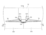
- FIG. 2 is an explanatory diagram clearly showing the split position with respect to the schematic front view of the cored bar.
- the displacement directions (split operation direction or movement direction) of the first mold 10-1, the second mold 10-2, and the third mold 12 are indicated by arrows 111, 110, and 112, respectively.
- a line denoted by reference numeral 104 indicates a split position between the first mold 10-1, the second mold 10-2, and the third mold 12.
- a line denoted by reference numeral 103 is a split position between the first mold 10-1 and the second mold 10-2 shown in FIG.
- the first mold 10-1 and the second mold 10-2 are used to cast a portion such as the wing portion 54 of the cored bar 52, and the third mold 12 is used to guide the guide protrusion 56 and the anti-roll-off protrusions 42, 43, etc.
- the part of is cast.
- the rubber crawler core metal manufacturing method of the present invention and the mold used therefor can be applied to the manufacture of a typical core metal having a pair of guide protrusions and the like. As a result, productivity of manufacturing a typical cored bar can be improved.
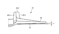
- FIG. 3 relates to the rubber crawler manufacturing method of the present invention and the first embodiment of the mold used therefor, and the first mold 10-1 and the second mold 10-2 are wing portions of the cored bar 52 to be cast.
- 5 is an explanatory view in which a slipping angle ⁇ is provided at the bottom 55 of the cored bar 52 so that it can be easily pulled out from the core 54.
- the draft angle ⁇ represents an angle formed between the bottom 55 of the wing portion 54 and the horizontal line when the core metal 52 is viewed from the front.
- the gradient ⁇ is zero, it is difficult to remove the mold.
- the gradient ⁇ is set to a small angle, and this gradient ⁇ can be made zero when the product is finished by utilizing deformation that occurs during the casting of the metal core and during the heat treatment.
- FIG. 4 is a schematic plan view of the mold (FIG. 4 (a)) and a schematic side view (FIG. 4 (a)) according to the second embodiment of the method for manufacturing a rubber crawler mandrel of the present invention and the mold used therefor. )).
- the core metal mold 18 is shown on the assumption that the mold 16 is transparent.
- the core bar cast in the present embodiment has no complicated irregularities in the central portion in the longitudinal direction of the core bar, and the first mold 16-1 And the one that can be manufactured only by the second mold 16-2.
- the cored bar to be cast is a cored bar having a unimodal guide protrusion protruding toward the inner peripheral surface side of the crawler body.
- the wheel passes through both outer sides with a single-peak guide protrusion interposed therebetween.
- the core metal mold 18 is arranged with its longitudinal direction the same as the split operation direction of the mold 16 or the vertical (depth) direction, and the core metal to be cast is the first Casting is performed using only the mold 16-1 and the second mold 16-2.
- the core metal mold 18 arranged in one mold 16 has an area occupied by the core metal frame 18 in the mating surface of the mold 16 in a direction perpendicular to the longitudinal direction of the core metal. Since the sectional area of the cut cored bar is smaller than the sectional area cut in the longitudinal direction of the cored bar, as a result, the number of cored molds 18 that can be arranged can be increased. As an example, in FIG.
- 3 ⁇ 4 core molds 18 can be arranged in one mold 16, and the production amount is doubled compared to the conventional manufacturing method.
- the draft ⁇ for facilitating the extraction of the first mold 16-1 and the second mold 16-2 from the cast cored bar is the same as in the first embodiment.
- the split position between the first mold 16-1 and the second mold 16-2 is indicated by a line 105.
- the first mold 16-1 and the second mold 16-2 are divided at substantially the center in the longitudinal direction of the core metal, the first mold 16-1 and the second mold 16-2 are separated from each other. The balance of the mass is good and each mold can be easily manufactured. Further, since the mass balance is good, the first mold 16-1 and the second mold 16-2 can be easily removed from the cast cored bar. That is, the unplugging operation is easy.
- the arrangement of the core dies in the mold is arranged in the vertical (depth) direction of the mold. Since the longitudinal direction is matched and the splitting direction of the mold is the longitudinal direction of the core metal, many core metal molds can be arranged in the mating surface of one mold, and the number of core bars that can be cast with one mold Can be increased. This can be said that when the vertical space of the container for storing the mold can be sufficiently secured, the vertical space can be used effectively. Therefore, the productivity of the rubber crawler core metal has been improved, and it has become possible to provide a high performance and high quality rubber crawler metal core at a low cost.
- the cored bar has protrusions for preventing wheel removal formed continuously from the pair of guide protrusions in the circumferential direction of the crawler body, and the circumferential tip of the core bar is different in the opposing direction.
- the present invention is not limited to this, and for example, there may be a mountain-shaped protrusion formed in the circumferential direction where the anti-roll-out preventing protrusion and a bifurcated protrusion engaged therewith are not particularly limited.
- correspond to a more complicated shape
Landscapes
- Engineering & Computer Science (AREA)
- Mechanical Engineering (AREA)
- Chemical & Material Sciences (AREA)
- Combustion & Propulsion (AREA)
- Transportation (AREA)
- Molds, Cores, And Manufacturing Methods Thereof (AREA)
Abstract
1つの鋳型で鋳造できる芯金の数量を増加させ、大幅なコスト改善を図ったゴムクローラ用芯金の製造方法を提供すること。 無端帯状のクローラ本体に埋設される芯金を、第1鋳型10-1と第2鋳型10-2を合わせ面にて合わせて鋳造するゴムクローラ用芯金の鋳型において、第1鋳型10-1と第2鋳型10-2を合わせ面にて合わせたときに形成される芯金型14の型空間は、上記の合わせ面からそれぞれ第1鋳型10-1と第2鋳型10-2の深さ方向に、上記の芯金型14の型空間の長手方向が形成されたことを特徴とする。
Description
本発明は、ゴムクローラ用芯金の製造方法及びそれに用いる鋳型、特にゴムクローラ用芯金を鋳造法により製造するゴムクローラ用芯金の製造方法及びそれに用いる鋳型に関する。
内部に芯金を有するゴムクローラは、無端帯状のクローラ本体の周方向に複数の芯金が並べて配置されている。それらの芯金は細長形状を有している。芯金は、芯金の長手方向がクローラ本体の周方向と直交するように配置される。芯金には、長手方向の略中央部に一対のガイド突起が形成され、これらのガイド突起の間をスプロケット及びアイドラーが通過し、また一対のガイド突起の上部を転輪が通過するように構成されているものもある。ここで、スプロケットはゴムクローラに駆動力を与えるものであり、アイドラーはゴムクローラに張力を付与するものであり、転輪はゴムクローラを円滑に前進及び後退させるためのものである。
更に、芯金には、上記のガイド突起がクローラ本体の幅方向にずれることのないように互いに係合し合う別の突起が設けられ、幅方向の大きなずれ、いわゆる脱輪の発生を防止しているものもある。この別の突起を脱輪防止突起と称する。これは、クローラ本体の周方向に並べて埋設された芯金のガイド突起が、クローラ本体の幅方向に不揃いな状態になると、スプロケット、アイドラー、又は転輪が通過する際に脱輪し易くなるので、これを防止するためのものである。
図5(a)は、芯金に上述のガイド突起と脱輪防止突起の両方の突起が設けられているゴムクローラ用芯金の概略平面図である。同図(b)は概略正面図、同図(c)は概略側面図である。なお、この芯金は、芯金にガイド突起と脱輪防止突起の両方の突起が設けられた芯金の一例として示しており、その他にも多くの種類がある。
芯金52は、芯金52の長手方向の略中央部に一対のガイド突起56-1、56-2を有している。それらのガイド突起56-1、56-2の突起方向は接地面に垂直、すなわちクローラ本体の内周面側であり、それぞれのガイド突起56-1、56-2から当該芯金のクローラ本体の幅方向外側に向かう翼部(羽根部)54が延在している。一対のガイド突起56-1、56-2の間は、スプロケット(図示していない)及びアイドラー(図示していない)が通過する駆動領域50を形成し、一対のガイド突起56-1、56-2の上部の頂面56a-1、56a-2は転輪通過面を構成している。
幅方向の大きなずれを防止するための脱輪防止突起42、43は、一対のガイド突起56-1、56-2に連続して形成されている。これらの突起42-1、42-2、43-1、43-2は、突起方向がクローラ本体の周方向(接地面と平行)であり、突起42-1、42-2と突起43-1、43-2は、それぞれ相反する周方向に突出して形成されている。それらの突起42、43の周方向の先端部の間隔はそれぞれ異なっており、突起42-1、42-2の間に、隣の芯金の突起43-1、43-2が係合するように構成されている。また、脱輪防止突起42、43の上部の頂面は、高さが一対のガイド突起56-1、56-2の頂面の高さと同じに形成され、かつ一対のガイド突起56-1、56-2の上面56a-1、56a-2と同一面に形成され、転輪通過面を構成している。したがって、一対のガイド突起56-1、56-2の上部の頂面56a-1、56a-2と、脱輪防止突起42、43の上部の頂面とは、平面視でいわゆるS字型のクランク状になっている。なお、脱輪防止突起42、43の上部の頂面については、相対する周方向の両端部でガイド突起56の頂面の中央部よりも僅かに高くした形状も存在する。このように構成することで、ゴムクローラの振動を低減することが可能である。
芯金は、芯金の形状に対応した芯金型を持つ鋳型に、溶融した材料(鉄)を注入し、そのまま凝固させるという方法(鋳造法)で製作される。この鋳造法においては、鋳型の合わせ面、又は割り位置をどのように設定するかが、鋳造される芯金の特性に影響を与える(例えば、特許文献1参照)。図6(a)は、芯金を鋳造法で製作するときの鋳型の概略平面図を示す。図6(b)は、この鋳型60の概略側面図である。ただし、図6(a)、図6(b)では、芯金型62は、鋳型60が透明であるとして示しており、実際には外部からは芯金型62は視認できない。また、芯金型62は図5で示す芯金に対応しているが、これは一例として示した。
鋳型60は、第1鋳型60-1と第2鋳型60-2に分離され、符号100が付されたラインは割り位置を表す(図6(b)参照)。割り位置とは、凝固した製品(鋳造された芯金)を取り出す際に、鋳型60をどの位置で割り動作させるのかを示したものである。図6では、第1鋳型60-1と第2鋳型60-2は、芯金を水平に置いたときの芯金の上下方向に分離される。言い換えると、鋳型60-1、60-2の合わせ面は、芯金の高さ(厚さ)方向を分割している。この図6で示した鋳型60を用いたゴムクローラ用芯金の製造方法を本明細書中では水平割りと称している。
一方、図7は水平割りとは別の縦割りについて示している。図7(a)は鋳型の概略平面図、図7(b)は鋳型の概略側面図である。ただし、図7(a)、(b)では、図6と同様に、芯金型66は、鋳型64が透明であるとして示しており、実際には外部からは芯金型66は視認できない。鋳型64は、第1鋳型64-1と第2鋳型64-2に分離され、符号101が付されたラインは割り位置を表す。この図7では、芯金を横にして立てた(短幅方向を立てた)ときの上下方向に分離される。言い換えると、鋳型64-1、64-2の合わせ面は、芯金の短幅方向を分割している。なお、図7の芯金型66は、図6の芯金型62と同一ではないが、それぞれ水平割り、縦割りの製造方法で製造できる芯金の一例として示している。
上述の水平割り及び縦割りによるゴムクローラ用芯金の製造方法は、高性能・高品質な芯金を製造する優れた製造方法である。しかし、それらの製造方法では、鋳型内での芯金型の配置は、芯金の長手方向を鋳型の幅方向又は長さ方向に揃えて行われる。鋳型の上下(深さ)方向は、芯金の高さ又は短幅方向の長さをカバーすれば良いので薄いものになっている。したがって、鋳型の合わせ面における1つの芯金型が占める面積は、芯金の長手方向で切断した断面積を含むため大きくなり、その数量が限られていた。その結果、1つの鋳型から鋳造できる芯金の数量が少なく、芯金の製造コストが高く付いていた。
本発明は、上記課題に鑑みてなされたものであり、その目的は、1つの鋳型で鋳造できる芯金の数量を増加させ、大幅なコスト改善を図ったゴムクローラ用芯金の製造方法及びそれに用いる鋳型を提供することにある。
上記目的を達成するため、請求項1に記載のゴムクローラ用芯金の製造方法は、無端帯状のクローラ本体に埋設される芯金であって細長形状を有する芯金を、第1と第2の鋳型を合わせ面にて合わせて鋳造するゴムクローラ用芯金の製法方法において、前記鋳造は、前記第1鋳型と前記第2鋳型の割り動作方向を芯金の長手方向として行われることを特徴とする。
通常、芯金は細長い形状を有しているが、上記方法により、鋳造された芯金を取り出す際の第1鋳型と第2鋳型の割り動作方向は、芯金の長手方向と同じ方向となる。その長手方向に直交する方向で切断した芯金の断面積は、長手方向で切断した断面積よりも小さい。したがって、合わせ面における1つの芯金型が占める面積はより小さくなり、結果として1つの鋳型の合わせ面内に配置される芯金型の数量を多くすることができる。すなわち、1回の鋳造工程でより多くの芯金を製造することが可能となる。例えば、試作した例では、同一面積の合わせ面を有する鋳型で、一度に鋳造できる芯金の数量を2倍以上とすることができた。
請求項2に記載のゴムクローラ用芯金の製造方法は、請求項1に記載のゴムクローラ用芯金の製造方法において、前記第1鋳型と第2鋳型の合わせ面は、芯金の長手方向の略中心部に位置することを特徴とする。したがって、第1鋳型と第2鋳型の質量のバランスが良く、かつ第1鋳型と第2鋳型の抜き動作も容易となる。
請求項3に記載のゴムクローラ用芯金の製造方法は、請求項1又は2に記載のゴムクローラ用芯金の製造方法において、 前記芯金は、長手方向の中央部に少なくとも一対の突起を有しており、前記鋳造は、中子として前記一対の突起間の少なくとも頂部間領域の形成面を構成し該突起の突出方向に変位可能な第3鋳型を、前記第1鋳型と前記第2鋳型の間に挿入して行われることを特徴とする。したがって、芯金の長手方向中央部に一対の突起を有する典型的な芯金の製造方法に、本発明の製造方法を適用することができる。
上記目的を達成するため、請求項4に記載のゴムクローラ用芯金の鋳型は、無端帯状のクローラ本体に埋設される芯金を、第1と第2の鋳型を合わせ面にて合わせて鋳造するゴムクローラ用芯金の鋳型において、前記第1と第2の鋳型を合わせ面にて合わせたときに形成される芯金型の型空間は、前記合わせ面からそれぞれ前記第1と第2の鋳型の深さ方向に、該芯金型の型空間の長手方向が形成されたことを特徴とする。
この鋳型を用いることにより、第1と第2の鋳型の合わせ面において、1つの芯金型が占める面積は、芯金を長手方向に直交する方向で切断した芯金の断面積であるから、芯金の長手方向で切断した断面積より小さく、結果として1つの鋳型の合わせ面内に多くの芯金型を配置することができる。すなわち、1回の鋳造工程でより多くの芯金を製造することが可能となる。例えば、試作した例では、同一面積の合わせ面を有する鋳型で、一度に鋳造できる芯金の数量を2倍以上とすることができた。
請求項5に記載のゴムクローラ用芯金の鋳型は、請求項4に記載のゴムクローラ用芯金の鋳型において、前記芯金は、長手方向の中央部に少なくとも一対の突起を有しており、前記鋳型は、中子として前記一対の突起間の少なくとも頂部間領域の形成面を構成し該突起の突出方向に変位可能な第3鋳型を、前記第1鋳型と前記第2鋳型の間に有することを特徴とする。したがって、芯金の長手方向中央部に一対の突起を有する典型的な芯金の製造方法に、本発明の鋳型を適用することができる。
本発明のゴムクローラ用芯金の製造方法及びそれに用いる鋳型によれば、芯金は、芯金の長手方向を割り動作方向とする第1鋳型と第2鋳型で製造できるので、1つの鋳型で多数の芯金を製造することが可能であり、生産性の向上が達成される。したがって、ゴムクローラ用芯金の低コスト化が図れることとなる。
(第1の実施の形態)
本発明の実施の形態を、以下図面を参照しながら詳述する。図1(a)は、本発明のゴムクローラ用芯金の製造方法及びそれに用いる鋳型の第1の実施の形態に係り、同図(a)は鋳型の概略平面図、同図(b)は概略側面図である。ただし、芯金型14は鋳型10が透明と仮定して示している。
本発明の実施の形態を、以下図面を参照しながら詳述する。図1(a)は、本発明のゴムクローラ用芯金の製造方法及びそれに用いる鋳型の第1の実施の形態に係り、同図(a)は鋳型の概略平面図、同図(b)は概略側面図である。ただし、芯金型14は鋳型10が透明と仮定して示している。
芯金型14は、鋳造される芯金が図5で説明したものと同一のものを想定し、一例として示している。すなわち、鋳造される芯金は、長手方向の略中央部に一対のガイド突起を有しており、それぞれのガイド突起から当該芯金の長手方向の両外側に向かう翼部が延在している。更に、幅方向の大きなずれを防止するための脱輪防止突起が、一対のガイド突起に連続して形成されている。
本願発明のクローラ用芯金の製造方法及びそれに用いる鋳型の特徴は、図1(a)、(b)に示すように、鋳型10内での芯金型14は、芯金の長手方向と鋳型10の割り動作方向が一致するように配置される。また、芯金の長手方向は、鋳型10の上下(深さ)方向と一致している。言い換えれば、第1鋳型10-1と第2鋳型10-2の合わせ面から、それぞれ第1と第2の鋳型の深さ方向に芯金型14の型空間の長手方向が形成されている。したがって、1つの鋳型10に配置される芯金型14は、鋳型10の合わせ面内で芯金型14の占める面積は、芯金を長手方向に直交する方向で切断した芯金の断面積であるから、芯金の長手方向で切断した断面積より小さく、結果として、1つの鋳型10に配置できる芯金型14の数量を多くすることが可能である。一例として、図1では3×4台であり、この数量は従来の製造方法に比べて2倍である。
また、第1鋳型10-1と第2鋳型10-2の間には、中子としての第3鋳型12が挿入される。この第3鋳型12は、一対のガイド突起間の頂部間領域の形成面を構成し、該突起の突出方向に変位可能になっている。すなわち、鋳造される芯金の長手方向の略中央部にはガイド突起及び脱輪防止突起が形成されるため、第1鋳型10-1と第2鋳型10-2だけで製造した場合は、第1鋳型10-1又は第2鋳型10-2が、芯金の長手方向に抜くことが困難なためである。したがって、中子としての第3鋳型12は、芯金の長手方向と直交するガイド突起の突出方向に抜けられるように構成されている。このように第3鋳型12を用いることで、高い生産性を維持したまま長手方向の中央部に複雑な形状を有するゴムクローラ用芯金を容易に製造することが可能である。なお、第1鋳型10-1と第2鋳型10-2の割り位置を、符号103を付したラインで示している。また、第1鋳型10-1と第3鋳型12との割り位置を符号96で、第2鋳型10-2と第3鋳型12との割り位置を符号98で示している。
更に、芯金の長手方向の略中心部で第1鋳型10-1と第2鋳型10-2が分割されるので、第1鋳型10-1と第2鋳型10-2との質量のバランスが良く、それぞれの鋳型を容易に製作することができる。また、質量のバランスが良いので第1鋳型10-1と第2鋳型10-2を、鋳造された芯金から容易に抜くことが可能である。すなわち、抜き動作が容易である。
図2は、芯金の概略正面図に対して割り位置を明示した説明図である。第1鋳型10-1、第2鋳型10-2及び第3鋳型12のそれぞれの変位方向(割り動作方向または移動方向)を矢印111、110、112で示している。符号104を付したラインが、第1鋳型10-1及び第2鋳型10-2と、第3鋳型12との割り位置を示す。符号103を付したラインは、図1(b)で示した第1鋳型10-1と第2鋳型10-2の割り位置である。したがって、第1鋳型10-1と第2鋳型10-2により芯金52の翼部54等の部分が鋳造され、第3鋳型12により中央部のガイド突起56及び脱輪防止突起42、43等の部分が鋳造される。このように、第3鋳型12を用いることで、一対のガイド突起等を有する典型的な芯金の製造に本発明のゴムクローラ用芯金の製造方法及びそれに用いる鋳型を適用することができる。その結果、典型的な芯金の製造の生産性を向上させることができることとなる。
図3は、本発明のゴムクローラの製造方法及びそれに用いる鋳型の第1の実施の形態に係り、第1鋳型10-1及び第2鋳型10-2が、鋳造される芯金52の翼部54から抜け易いように、芯金52の底部55に抜け勾配αを設けた説明図である。この抜け勾配αは、芯金52を正面から見た場合、翼部54の底部55と水平線との為す角度を表しており、勾配αが零では鋳型が抜き難くなる。一方、勾配αが大きい場合には、芯金の特性に影響を及ぼす可能性が生じる。したがって、勾配αは小さい角度に設定しており、この勾配αは、芯金の鋳造時及び熱処理時に発生する変形を利用して製品仕上がり時には零とすることが可能である。
(第2の実施の形態)
図4は、本発明のゴムクローラ用芯金の製造方法及びそれに用いる鋳型の第2の実施の形態に係り、鋳型の概略平面図(同図(a))と概略側面図(同図(a))を示す。ただし、図1と同様に、芯金型18は鋳型16が透明であると仮定して示している。本実施の形態で鋳造される芯金は、第1の実施の形態で鋳造される芯金とは異なり、芯金の長手方向の中央部には複雑な凹凸がなく、第1鋳型16-1と第2鋳型16-2のみで製造できるものを示している。すなわち、鋳造される芯金は、クローラ本体の内周面側に突出する単峰性のガイド突起を有する芯金である。なお、この場合、転輪は単峰性のガイド突起を挟んで両外側を通過することとなる。
図4は、本発明のゴムクローラ用芯金の製造方法及びそれに用いる鋳型の第2の実施の形態に係り、鋳型の概略平面図(同図(a))と概略側面図(同図(a))を示す。ただし、図1と同様に、芯金型18は鋳型16が透明であると仮定して示している。本実施の形態で鋳造される芯金は、第1の実施の形態で鋳造される芯金とは異なり、芯金の長手方向の中央部には複雑な凹凸がなく、第1鋳型16-1と第2鋳型16-2のみで製造できるものを示している。すなわち、鋳造される芯金は、クローラ本体の内周面側に突出する単峰性のガイド突起を有する芯金である。なお、この場合、転輪は単峰性のガイド突起を挟んで両外側を通過することとなる。
図4(b)に示すように、芯金型18は、その長手方向が鋳型16の割り動作方向、または上下(深さ)方向と同一にして配置され、鋳造される芯金は、第1鋳型16-1と第2鋳型16-2のみを用いて鋳造される。第1の実施の形態と同様に、1つの鋳型16に配置される芯金型18は、鋳型16の合わせ面内で芯金枠18の占める面積は、芯金を長手方向に直交する方向で切断した芯金の断面積であるから、芯金の長手方向で切断した断面積より小さく、結果として、配置できる芯金型18の数量を多くすることが可能である。一例として、図4(a)では、1つの鋳型16に3×4台の芯金型18を配置することができ、従来の製造方法に比較して生産量が2倍となる。なお、第1鋳型16-1及び第2鋳型16-2を鋳造された芯金から抜き易くするための抜き勾配αに関しては、第1の実施の形態と同様である。なお、第1鋳型16-1と第2鋳型16-2との割り位置をライン105で示した。本実施の形態においても、芯金の長手方向の略中心部で第1鋳型16-1と第2鋳型16-2が分割されるので、第1鋳型16-1と第2鋳型16-2との質量のバランスが良く、それぞれの鋳型を容易に製作することができる。また、質量のバランスが良いので第1鋳型16-1と第2鋳型16-2を、鋳造された芯金から容易に抜くことが可能である。すなわち、抜き動作が容易である。
第1及び第2の実施の形態のゴムクローラ用芯金の製造方法及びそれに用いる鋳型によれば、鋳型内での芯金型の配列を、鋳型の上下(深さ)方向に芯金型の長手方向を合わせ、鋳型の割り動作方向を芯金の長手方向としたので、1つの鋳型の合わせ面内に芯金型を数多く配列することが可能となり、1つの鋳型で鋳造できる芯金の数量を増加することができる。このことは、鋳型を収納する容器の上下方向のスペースが十分に確保できる場合は、この上下方向のスペースを有効に利用できるようになったと言える。したがって、ゴムクローラ用芯金の生産性が向上し、高性能・高品質なゴムクローラ芯金を低コストで提供することが可能となった。
なお、本発明は、上述の実施の形態に限定されるものではなく、本発明の趣旨を逸脱しない範囲で種々の変更が可能である。例えば、芯金は、脱輪防止のための突起が一対のガイド突起から連続してクローラ本体の周方向に形成され、その周方向先端部の間隔が相対する方向で異なるものを示したが、これに限らず、例えば、脱輪防止突起が相対する周方向に形成された山形突起とそれに係合する二股突起のものであっても良く特に制限はない。また、鋳型をより複雑な形状に対応させるために、第4鋳型又はそれ以上の鋳型により、芯金を製造することもできる。
10、16、60、64 鋳型
10-1、16-1、60-1、64-1 第1鋳型
10-2、16-2、60-2、64-2 第2鋳型
12 第3鋳型(中子)
14、18、62、66 芯金型
50 駆動領域
52 ゴムクローラ用芯金
42-1、42-2、43-1、43-2 脱輪防止突起
54 翼部
56-1、56-2 ガイド突起
56a-1、56a-2 頂面
96、98、100、101、103、104、105 鋳型の割り位置
α 抜き勾配
10-1、16-1、60-1、64-1 第1鋳型
10-2、16-2、60-2、64-2 第2鋳型
12 第3鋳型(中子)
14、18、62、66 芯金型
50 駆動領域
52 ゴムクローラ用芯金
42-1、42-2、43-1、43-2 脱輪防止突起
54 翼部
56-1、56-2 ガイド突起
56a-1、56a-2 頂面
96、98、100、101、103、104、105 鋳型の割り位置
α 抜き勾配
Claims (5)
- 無端帯状のクローラ本体に埋設される芯金を、第1と第2の鋳型を合わせ面にて合わせて鋳造するゴムクローラ用芯金の製法方法において、
前記鋳造は、前記第1鋳型と前記第2鋳型の割り動作方向を芯金の長手方向として行われることを特徴とするゴムクローラ用芯金の製造方法。 - 前記第1鋳型と前記第2鋳型の合わせ面は、芯金の長手方向の略中心部に位置することを特徴とする請求項1に記載のゴムクローラ用芯金の製造方法。
- 前記芯金は、長手方向の中央部に少なくとも一対の突起を有しており、
前記鋳造は、中子として前記一対の突起間の少なくとも頂部間領域の形成面を構成し該突起の突出方向に変位可能な第3鋳型を、前記第1鋳型と前記第2鋳型の間に挿入して行われることを特徴とする請求項1又は2に記載のゴムクローラ用芯金の製造方法。 - 無端帯状のクローラ本体に埋設される芯金を、第1と第2の鋳型を合わせ面にて合わせて鋳造するゴムクローラ用芯金の鋳型において、
前記第1と第2の鋳型を合わせ面にて合わせたときに形成される芯金型の型空間は、
前記合わせ面からそれぞれ前記第1と第2の鋳型の深さ方向に、該芯金型の型空間の長手方向が形成されたことを特徴とするゴムクローラ用芯金の鋳型。 - 前記芯金は、長手方向の中央部に少なくとも一対の突起を有しており、
前記鋳型は、中子として前記一対の突起間の少なくとも頂部間領域の形成面を構成し該突起の突出方向に変位可能な第3鋳型を、前記第1鋳型と前記第2鋳型の間に有することを特徴とする請求項4に記載のゴムクローラ用芯金の鋳型。
Applications Claiming Priority (2)
| Application Number | Priority Date | Filing Date | Title |
|---|---|---|---|
| JP2010091962A JP5596401B2 (ja) | 2010-04-13 | 2010-04-13 | ゴムクローラ用芯金の製造方法及びそれに用いる鋳型 |
| JP2010-091962 | 2010-04-13 |
Publications (1)
| Publication Number | Publication Date |
|---|---|
| WO2011129240A1 true WO2011129240A1 (ja) | 2011-10-20 |
Family
ID=44798616
Family Applications (1)
| Application Number | Title | Priority Date | Filing Date |
|---|---|---|---|
| PCT/JP2011/058703 Ceased WO2011129240A1 (ja) | 2010-04-13 | 2011-04-06 | ゴムクローラ用芯金の製造方法及びそれに用いる鋳型 |
Country Status (2)
| Country | Link |
|---|---|
| JP (1) | JP5596401B2 (ja) |
| WO (1) | WO2011129240A1 (ja) |
Families Citing this family (2)
| Publication number | Priority date | Publication date | Assignee | Title |
|---|---|---|---|---|
| JP6958282B2 (ja) * | 2017-11-22 | 2021-11-02 | 住友ゴム工業株式会社 | ゴムクローラ用の芯材及びゴムクローラ |
| JP7231463B2 (ja) * | 2019-04-09 | 2023-03-01 | 株式会社ブリヂストン | クローラ用芯部材及び弾性クローラ |
Citations (3)
| Publication number | Priority date | Publication date | Assignee | Title |
|---|---|---|---|---|
| JP2001334971A (ja) * | 2000-05-29 | 2001-12-04 | Bridgestone Corp | ゴムクローラ用芯金及びその製法 |
| JP2004025210A (ja) * | 2002-06-24 | 2004-01-29 | Asahi Tec Corp | 鋳型 |
| JP2009078581A (ja) * | 2007-09-25 | 2009-04-16 | Bridgestone Corp | ゴムクローラ用芯金およびそれを用いたゴムクローラ |
-
2010
- 2010-04-13 JP JP2010091962A patent/JP5596401B2/ja not_active Expired - Fee Related
-
2011
- 2011-04-06 WO PCT/JP2011/058703 patent/WO2011129240A1/ja not_active Ceased
Patent Citations (3)
| Publication number | Priority date | Publication date | Assignee | Title |
|---|---|---|---|---|
| JP2001334971A (ja) * | 2000-05-29 | 2001-12-04 | Bridgestone Corp | ゴムクローラ用芯金及びその製法 |
| JP2004025210A (ja) * | 2002-06-24 | 2004-01-29 | Asahi Tec Corp | 鋳型 |
| JP2009078581A (ja) * | 2007-09-25 | 2009-04-16 | Bridgestone Corp | ゴムクローラ用芯金およびそれを用いたゴムクローラ |
Also Published As
| Publication number | Publication date |
|---|---|
| JP2011218425A (ja) | 2011-11-04 |
| JP5596401B2 (ja) | 2014-09-24 |
Similar Documents
| Publication | Publication Date | Title |
|---|---|---|
| JP5097482B2 (ja) | ゴムクローラおよびそのゴムクローラ用芯金 | |
| EP2119620B1 (en) | Rubber crawler track | |
| US10449599B2 (en) | Track link and method for manufacturing track link | |
| JP5603385B2 (ja) | 弾性クローラの製造方法および弾性クローラ製造用の加硫成形金型 | |
| JP5596401B2 (ja) | ゴムクローラ用芯金の製造方法及びそれに用いる鋳型 | |
| JP5264224B2 (ja) | 弾性クローラ | |
| JP2004216936A (ja) | ゴムクロ−ラ | |
| JP2010012806A (ja) | 弾性クローラ | |
| JP5330775B2 (ja) | 弾性クローラ | |
| JP4888296B2 (ja) | ラック軸の製造方法 | |
| JP5431750B2 (ja) | ゴムクローラ用芯金 | |
| WO2018135643A1 (ja) | ゴムクローラ、ゴムクローラ成形金型、及びゴムクローラの製造方法 | |
| JP5940327B2 (ja) | クローラ用芯金、弾性クローラ、及びクローラ用芯金の鋳型 | |
| JP6013707B2 (ja) | ゴムクローラの製造方法 | |
| JP5164498B2 (ja) | ゴムクローラ用芯金およびそれを用いたゴムクローラ | |
| JP6076586B2 (ja) | ゴムクローラ、ゴムクローラ組立体、及び、ゴムクローラ製造方法 | |
| JP2953536B2 (ja) | ゴムクロ−ラ用芯金 | |
| JP6076585B2 (ja) | ゴムクローラ、ゴムクローラ組立体、及び、ゴムクローラ製造方法 | |
| JP5871488B2 (ja) | ゴムクローラ | |
| JP6958282B2 (ja) | ゴムクローラ用の芯材及びゴムクローラ | |
| JP2024060287A (ja) | 金型装置 | |
| CN212498812U (zh) | 电视机中框模具 | |
| JP5485566B2 (ja) | ゴムクローラ用芯金及び該芯金を使用したゴムクローラ | |
| JP4442067B2 (ja) | サイプ板の製作方法 | |
| JP2010012839A (ja) | 弾性クローラ用芯金及びその製造方法 |
Legal Events
| Date | Code | Title | Description |
|---|---|---|---|
| 121 | Ep: the epo has been informed by wipo that ep was designated in this application |
Ref document number: 11768761 Country of ref document: EP Kind code of ref document: A1 |
|
| NENP | Non-entry into the national phase |
Ref country code: DE |
|
| 122 | Ep: pct application non-entry in european phase |
Ref document number: 11768761 Country of ref document: EP Kind code of ref document: A1 |