WO2011129166A1 - 車両 - Google Patents
車両 Download PDFInfo
- Publication number
- WO2011129166A1 WO2011129166A1 PCT/JP2011/055572 JP2011055572W WO2011129166A1 WO 2011129166 A1 WO2011129166 A1 WO 2011129166A1 JP 2011055572 W JP2011055572 W JP 2011055572W WO 2011129166 A1 WO2011129166 A1 WO 2011129166A1
- Authority
- WO
- WIPO (PCT)
- Prior art keywords
- air
- vehicle
- outlets
- ion
- ions
- Prior art date
- Legal status (The legal status is an assumption and is not a legal conclusion. Google has not performed a legal analysis and makes no representation as to the accuracy of the status listed.)
- Ceased
Links
Images


Classifications
-
- B—PERFORMING OPERATIONS; TRANSPORTING
- B61—RAILWAYS
- B61D—BODY DETAILS OR KINDS OF RAILWAY VEHICLES
- B61D27/00—Heating, cooling, ventilating, or air-conditioning
-
- B—PERFORMING OPERATIONS; TRANSPORTING
- B60—VEHICLES IN GENERAL
- B60H—ARRANGEMENTS OF HEATING, COOLING, VENTILATING OR OTHER AIR-TREATING DEVICES SPECIALLY ADAPTED FOR PASSENGER OR GOODS SPACES OF VEHICLES
- B60H3/00—Other air-treating devices
- B60H3/0071—Electrically conditioning the air, e.g. by ionizing
- B60H3/0078—Electrically conditioning the air, e.g. by ionizing comprising electric purifying means
Definitions
- the present invention generally relates to a vehicle, and more particularly to a vehicle such as a railway vehicle or a bus provided with a blow-out port for blowing out air in order to adjust the air in the vehicle.
- Bacteria, pollen, dust, etc. are minute things that are invisible, and usually move while floating in the air. And fungi, pollen, dust and the like naturally fall with the passage of time, and finally fall to the floor surface or the ground. Therefore, the vicinity of the floor of the vehicle is in a state where there are very many bacteria, pollen, dust and the like. Although it depends on the environmental conditions in the vehicle, the bacteria after dropping can easily propagate, and a large number of bacteria may live on the floor in the vehicle. In particular, since the floor surface in the vehicle is often wet on a rainy day, the floor surface in the vehicle on a rainy day is in a perfect condition for the propagation of bacteria.
- Patent Document 1 proposes an ion control vehicle.
- the ion control vehicle includes a plurality of chairs, a positive / negative ion generator that emits ions from the back of any of the plurality of chairs, a rotation axis that changes the orientation of any of the plurality of chairs, and a chair that has the rotation axis changed.
- the ion control vehicle disclosed in Patent Document 1 releases ions from the back of the seat and removes bacteria and the like by the ions.
- the released ions are likely to reach a portion higher than the seat seat surface, but may not reach the vicinity of the floor surface where the most bacteria are present (bred). That is, ions reach the passenger sitting in the seat, but there are few ions that reach the floor, which is a breeding source of bacteria, and the effect of removing the bacteria is small.
- the ion control vehicle disclosed in Patent Document 1 can be applied to a railway vehicle in which seats are arranged in the traveling direction such as a Shinkansen, but the seats face in the left-right direction like conventional lines. There is a problem that it cannot be applied to railway vehicles that are lined up.
- Patent Document 2 proposes a vehicle having an ion generator in the lower part of the seat.
- This vehicle is a vehicle in which a plurality of seats including a first seat and a second seat are arranged.
- the first seat is disposed under the first seat and generates a first positive / negative ion generator that generates positive / negative ions, a first suction port that communicates with the first positive / negative ion generator, A first air outlet formed in the lower portion of the seat and communicated with the first positive / negative ion generator; and disposed on a path from the first air inlet to the first air outlet; And a first blower for sending air to one outlet.
- the second seat is disposed in the lower portion of the second seat and is formed in a second positive and negative ion generator that generates positive and negative ions, and is formed in the lower portion of the second seat and communicated with the second positive and negative ion generator.
- air containing a large amount of positive and negative ions generated by a positive and negative ion generator is placed on and near the floor surface where a lot of bacteria, pollen, dust, and the like are present. Can be supplied. Then, the air containing a large amount of positive and negative ions generated by the positive and negative ion generator removes or prevents bacteria, pollen, dust, etc. on the floor surface between the first seat and the second seat, and in the vicinity of the floor surface. Activate. As a result, the air in the vehicle can be efficiently purified.
- Patent Document 2 is also arranged in a railcar in which seats are arranged in the traveling direction such as a Shinkansen, and the seats are arranged facing the left and right directions as in a conventional line. It can also be applied to railway vehicles.
- an ion generator is provided on the back of each seat. Moreover, in the vehicle disclosed in Patent Document 2, an ion generator is provided in the lower part of each seat. For this reason, in the vehicles disclosed in Patent Document 1 and Patent Document 2, in order to distribute ions throughout the vehicle, it is necessary to provide ion generators in all seats, and the number of installed ion generators. There is a problem that the cost is increased because of the increase in the number of.
- an object of the present invention is to provide a vehicle capable of increasing the ion concentration in the vehicle without increasing the number of installed ion generators.
- the vehicle according to the present invention includes a plurality of first outlets and a plurality of second outlets.
- the plurality of first outlets are provided on the inner wall surface and blow out air to adjust the air in the vehicle.
- the plurality of second outlets are provided on the inner wall surface and blow out air containing ions.
- the plurality of first air outlets in the first air outlet arranged so that the air flow blown from the first air outlet intersects or is close to the air current blown from the second air outlet,
- the plurality of first air outlets are configured so that the speed of the air flow blown out from the first air outlet is lower than the speed of the air current blown out from the other first air outlets.
- the speed of the airflow blown out from the plurality of first air outlets is not constant to adjust the air in the vehicle, but the airflow blown out from the plurality of first air outlets is not constant. There is a height difference in speed.
- the air stream containing the ions blown out from the second outlet crosses or approaches the low-velocity air stream blown out from the first outlet.
- the airflow of air containing ions can be combined with the airflow of air-conditioning air without being blocked by the airflow of air-conditioning air and directed to the seat in the vehicle.
- the air containing a high concentration ion can be spread to the person sitting on the seat in the vehicle. Therefore, it is possible to increase the ion concentration in the vehicle without increasing the number of installed ion generators.
- the plurality of first outlets are arranged on the inner upper wall surface of the vehicle, and the plurality of second outlets are arranged on the inner upper wall surface of the vehicle located outside the plurality of first outlets. It is preferred that Also, the airflow blown from the first blowout port is blown down from the inner upper wall surface of the vehicle, and the airflow blown from the second blowout port is blown obliquely downward from the inner upper wall surface of the vehicle. Is preferred.
- the plurality of first outlets include a plurality of rectangular hole groups arranged in two rows so as to be aligned in the longitudinal direction of the vehicle.
- the vehicle of this invention is further provided with the some ion generator arrange
- the plurality of second outlets are outlets that blow out air containing ions from the plurality of ion generators.
- the plurality of ion generators are opposed to each other in the direction perpendicular to the longitudinal direction of the vehicle with the plurality of rectangular hole groups interposed therebetween, and are spaced in the longitudinal direction of the vehicle. It is preferable that they are arranged apart.
- the length of the vehicle is such that the plurality of ion generators face each other in a direction obliquely intersecting the length direction of the vehicle with the plurality of rectangular hole groups interposed therebetween. It is preferable that they are arranged at intervals in the direction.
- each of the plurality of ion generators is provided with a plurality of outlets for blowing out air containing ions in different directions.
- the ion species contained in the air blown out from the two blowout ports adjacent to each other in the plurality of blowout ports provided in each of the plurality of ion generators have different polarities.
- the ion concentration in the vehicle can be increased without increasing the number of installed ion generators.
- FIG. 1 is a side sectional view showing a basic configuration of a vehicle as an embodiment according to the present invention. It is a partial top view which shows the basic composition of the vehicle as 1st Embodiment seen from the direction of arrow II in the vehicle of FIG.
- FIG. 3 is a partial cross-sectional view showing a cross section along the length direction of the vehicle as seen from the direction of arrow III in the vehicle of FIG. 2.
- FIG. 4 is a partial top view showing a basic configuration of a vehicle as a second embodiment viewed from the direction of arrow IV in the vehicle of FIG. 1.
- FIG. 5 is a partial cross-sectional view showing a cross section along the length direction of the vehicle as viewed from the direction of arrow V in the vehicle of FIG. 4.
- FIG. 7 It is a perspective view which shows the form of the air outlet for an air conditioning used in the vehicle as embodiment of this invention. It is a perspective view which shows the external appearance of the ion generation unit used in the vehicle as embodiment of this invention. It is the disassembled perspective view which looked at the ion generation unit shown by FIG. 7 from the front. It is a disassembled perspective view of the main body base of the ion generation unit shown by FIG. It is the disassembled perspective view which looked at the ion generating unit shown by FIG. 7 from the rear surface. It is a top view of the case of the ion generation unit shown by FIG. It is a top view of the main body base of the ion generation unit shown by FIG.
- FIG. 2 It is a top view of the suction grill of the ion generation unit shown by FIG. It is a schematic diagram which shows the outline of the air ventilation path in the ion generation unit shown by FIG. It is a schematic diagram which shows the outline of the air ventilation path in the ion generation unit shown by FIG. It is a front view of the front panel of the ion generation unit shown in FIG. It is principal part sectional drawing of the air blower outlet of the ion generation unit shown by FIG. It is a figure which shows an example of the air blowing direction of the ion generation unit shown by FIG. It is a figure which shows the simulation result of the ion concentration distribution in the vehicle of 1st Embodiment shown by FIG. 2 and FIG.
- FIG. 4 is a partial top view showing a basic configuration of a vehicle as a third embodiment viewed from the direction of arrow IV in the vehicle of FIG. 1.
- FIG. 22 is a partial cross-sectional view showing a cross section along the length direction of the vehicle as viewed from the direction of arrow XXII in the vehicle of FIG. 21. It is a figure which shows the simulation result of the ion concentration distribution in the vehicle of 3rd Embodiment shown by FIG. 21 and FIG.
- a plurality of seats 700 are arranged in the vehicle 1000 in the traveling direction, that is, in the longitudinal direction of the vehicle.
- the plurality of seats 700 are arranged in two rows with a passage located at the center in the width direction of the vehicle 1000 interposed therebetween.
- a net shelf 600 is provided on both side walls in the vehicle 1000. Further, the net rack 600 is positioned on the seat 700 and is disposed so as to extend along each row of the two rows of seats 700.
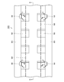
- An air-conditioning air outlet 500 as an example of a plurality of first outlets is provided on the inner upper wall surface of the vehicle 1000, that is, the ceiling wall surface. Air is blown out from the air-conditioning air outlet 500 to adjust the air in the vehicle 1000. As indicated by an arrow A, the airflow blown out from the air-conditioning air outlet 500 is blown out from the inner upper wall surface of the vehicle 1000 in the downward direction.
- the air-conditioning air outlets 500 are arranged in two rows so as to be aligned in the length direction of the vehicle 1000. In this embodiment, the air-conditioning air outlets 500 are arranged in two rows with a passage located at the center in the width direction of the vehicle 1000 interposed therebetween.
- the air-conditioning air outlet 500 includes a plurality of rectangular hole groups arranged in two rows, for example, a plurality of slit-shaped hole groups.
- the plurality of slit-shaped holes are arranged at intervals in the length direction of the vehicle 1000.
- the plurality of ion generators 100 are arranged on the inner upper wall surface of the vehicle 1000 located on both sides outside the air-conditioning air outlet 500, that is, on the inclined ceiling wall surface. Air containing ions is blown out from the air outlet of the ion generator 100 in order to remove airborne bacteria, airborne viruses, and the like present in the air in the vehicle 1000.
- four air outlets are provided in the ion generator 100 in order to blow out air containing ions in different directions.
- the ion species contained in the air blown out from two adjacent air outlets in the four air outlets provided in the ion generator 100 have different polarities.
- air containing positive ions (+), negative ions ( ⁇ ), positive ions (+), and negative ions ( ⁇ ) in order along the peripheral direction of the ion generator 100 is indicated by arrows.
- the air is blown out in four directions from the four air outlets.
- the airflow blown from the air outlet of the ion generator 100 is blown obliquely downward from the inner upper wall surface of the vehicle 1000.
- the air outlet of the ion generator 100 is an example of a plurality of second outlets. Details of the ion generator 100 will be described later.
- two ion generators 100 are arranged such that an air-conditioning air outlet 500, that is, a plurality of slit-shaped hole groups arranged in two rows is sandwiched between vehicles. It arrange
- a plurality of ion generators 100 are arranged side by side in the longitudinal direction of the vehicle 1000 at intervals.
- the air flow (arrow A) blown out from the air-conditioning air outlet 500 out of the plurality of air-conditioning air outlets 500 is the ion generator 100.
- the airflow (A) The plurality of air-conditioning air outlets 500 are configured so that the speed of the arrow) is lower than the speed of the airflow (arrow A) blown out from the other air-conditioning air outlets 500.
- the speed of the airflow (arrow A) blown out from the air-conditioning air outlet 500 arranged in the vicinity of the ion generator 100 is the speed of the airflow (arrow A in A) blown out from the other air-conditioning air outlet 500.
- the length of the arrow A indicating the air flow blown out from the air-conditioning air outlet 500 arranged in the vicinity of the ion generating device 100 is set to be different for other air-conditioning. It is displayed shorter than the length of the arrow A indicating the airflow blown out from the air outlet 500.
- the speed of the air flow blown out from the plurality of air conditioning air outlets 500 is not constant, but a plurality of air conditioning air outlets are used.
- a difference in height is provided in the velocity of the airflow blown out from 500.
- the air stream containing ions blown out from the air outlet of the ion generator 100 intersects or approaches the low-speed air stream blown out from the air-conditioning air outlet 500.
- the airflow of the air containing ions can be combined with the airflow of the air conditioning air without being blocked by the airflow of the air conditioning air, and can be directed to the seat 700 in the vehicle 1000.
- air containing high-concentration ions can be distributed to people sitting on the seat 700 in the vehicle 1000. Therefore, it is possible to increase the ion concentration in the vehicle without increasing the number of installed ion generators.
- a plurality of air-conditioning air outlets 500 as first outlets are arranged on the inner upper wall surface of the vehicle 1000.
- the air outlets of the plurality of ion generators 100 as the plurality of second outlets are arranged on the inner upper wall surface of the vehicle 1000 positioned outside the plurality of air conditioning air outlets 500.
- the airflow blown out from the air-conditioning air outlet 500 is blown out from the inner upper wall surface of the vehicle 1000 in the downward direction. Airflow blown from the air outlet of the ion generator 100 is blown obliquely downward from the inner upper wall surface of the vehicle 1000.
- the vehicle 1000 according to the present invention includes a plurality of rectangular holes arranged in two rows so that a plurality of air-conditioning air outlets 500 are arranged in the longitudinal direction of the vehicle 1000. Further, the vehicle 1000 of the present invention includes a plurality of ion generators 100 disposed on both sides of a plurality of air conditioning air outlets 500.
- a plurality of ion generators 100 face each other in a direction orthogonal to the length direction of the vehicle 1000 with a plurality of air-conditioning air outlets 500, that is, a plurality of rectangular hole groups interposed therebetween. And arranged at intervals in the longitudinal direction of the vehicle 1000.
- the bactericidal effect by ions that is, the effect of removing floating bacteria, floating viruses and the like by ions depends on the concentration of ions.
- concentration of ions the higher the ion concentration, the higher the effect.
- the ion concentration is 7000 / cm 3
- the residual rate of airborne virus becomes 1/100 in 10 minutes
- the ion concentration is 50000 / cm 3 .
- the residual rate of airborne virus becomes 1/1000 in 10 minutes.
- the deodorizing effect of the smell of cigarettes attached to clothes or the like is about twice as high when the ion concentration is 20000 / cm 3 as compared with the case where the ion concentration is 5000 / cm 3 .
- each of the plurality of ion generators 100 is provided with a plurality of air outlets that blow out air containing ions in different directions, so that the air containing the ions is generated. It can spread evenly from 100 to the surroundings.
- the ion species contained in the air blown out from two adjacent air outlets in the plurality of air outlets provided in each of the plurality of ion generators 100 have different polarities, so that positive ions It is possible to evenly diffuse from the ion generator 100 to the surroundings without neutralizing the negative ions.
- the two ion generators 100 are provided with air-conditioning air outlets 500, that is, a plurality of slit-shaped hole groups arranged in two rows. Are arranged so as to face each other in a direction that obliquely intersects the length direction of the vehicle 1000.
- a plurality of ion generators 100 are arranged side by side in the longitudinal direction of the vehicle 1000 at intervals.
- Other configurations in the second embodiment of the vehicle 1000 are the same as those in the first embodiment.
- the air current blown from the air-conditioning air outlet 500 (arrow A).
- the air-conditioning air outlet 500 arranged so as to intersect or be close to the air flow (+ and ⁇ arrows) blown out from the air outlet of the ion generator 100.
- the plurality of air conditioning air outlets 500 are configured so that the speed of the airflow (arrow A) is lower than the speed of the airflow (arrow A) blown from the other air conditioning air outlets 500. Yes.
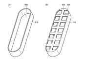
- the form of the plurality of air-conditioning air outlets 500 for this purpose will be described below.
- the passage through which the airflow passes is formed only by the peripheral side wall portion 510.
- the speed (air volume) of the blown airflow is large.
- the passage through which the airflow passes is a plurality of small outlets 520 and the peripheral side wall 510.
- Air volume becomes smaller.
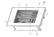
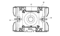
- the ion generation unit 100 includes a box-shaped case 40 having an open surface, a box-shaped main body base 30 having an open surface that is accommodated in the case 40, and an upper surface (front surface) of the main body base 30. And the front panel 10 as an air guide plate attached to the upper surface (front surface) of the suction grill 20.
- the front panel 10 of the ion generation unit 100 is provided with an air suction port 15 at the center.
- Air blowout ports 11, 12, 13, and 14 are provided on the same plane as the air suction port 15 so as to surround the air suction port 15.
- the same surface is not only when the air suction port and the air outlet are on the same plane as illustrated in the present embodiment, but also when they are on the same bent surface (for example, the air suction port When the normal direction of the opening surface and the normal direction of the opening surface of the air outlet are inclined to each other so as to form an acute angle), when they are parallel to each other (for example, the air inlet In the case where the opening surface and the opening surface of the air outlet are provided with a step).
- the air outlets 11 to 14 are arranged at substantially four corners of a rectangle surrounding the air inlet 15. Further, a filter (not shown) having substantially the same size can be attached to the back surface of the air suction port 15. Thereby, dust in the air can be removed.
- a suction hole 25 having substantially the same dimensions is provided on the front surface (upper surface) of the suction grill 20 at a position corresponding to the air suction port 15.
- Air outlets 21, 22, 23, and 24 having substantially the same dimensions are provided at positions corresponding to the air outlets 11 to 14, respectively.
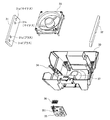
- the main body base 30 includes ion generating elements 31 and 32, a fan 33 including blades, a control unit 35 that controls the ion generating unit 100, a display unit 36 including LEDs, and the like. Is attached.
- the main body base 30 is configured such that a fan 33 is attached to the center.
- a bowl-shaped throttle portion 37 is formed that is narrowed in a circular shape from the outside to the inside.
- the pair of opposing side walls of the main body base 30 are formed to be inclined so as to expand toward the front surface (upper surface).
- Ion generating elements 31 and 32 are attached to the respective side walls.
- the ion generating elements 31 and 32 are attached to the side wall by being pressed by a fixing plate 34 having a locking portion formed at the tip.
- the ion generating elements 31 and 32 are detachably attached by a fixing plate 34.
- the ion generating element 31 is a rectangular plate. In the vicinity of one end portion of the ion generating element 31, electrode needles 31a and 31b as electrode portions for generating negative ions are provided with an appropriate length apart. In the vicinity of the other end portion of the ion generating element 31, electrode needles 31c and 31d as electrode portions for generating positive ions are provided with an appropriate length apart. In a state where the ion generating element 31 is attached, an ion generating electrode portion that generates negative ions is disposed in the vicinity of the outlet 21 and the air outlet 11. Air containing negative ions is blown out from the blowout hole 21 and the air blowout port 11.
- an ion generating electrode portion that generates positive ions is disposed in the vicinity of the blowout hole 24 and the air outlet 14 with the ion generating element 31 attached. Air containing positive ions is blown out from the blowout hole 24 and the air blowout port 14.
- the ion generating element 32 has the same configuration as the ion generating element 31. In a state where the ion generating element 32 is attached, an ion generating electrode portion that generates positive ions is disposed in the vicinity of the air outlet 22 and the air outlet 12. Air containing positive ions is blown out from the blowout hole 22 and the air blowout port 12. In addition, an ion generating electrode portion that generates negative ions is disposed in the vicinity of the blowout hole 23 and the air blowout port 13 with the ion generating element 32 attached. Air containing negative ions is blown out from the blowout hole 23 and the air blowout port 13.
- the ion generating elements 31 and 32 ionize water vapor in the air by plasma discharge, so that H + (H 2 O) n (n is an arbitrary natural number) as positive ions and O 2 ⁇ ( H 2 O) m (m is an arbitrary natural number). These chemically react to generate hydrogen peroxide (H 2 O 2 ) and / or hydroxyl radicals (OH), which are active species, and remove airborne bacteria and airborne viruses.
- each of the air outlets 11 to 14 can independently blow out air containing positive ions or air containing negative ions, and in the air blown out from the ion generation unit 100 Immediate neutralization of positive ions and negative ions can be prevented. And ion diffusibility can be improved by preventing neutralization of ions.
- the display unit 36 indicates the operation state of the ion generation unit (for example, whether the ion concentration is generated or not, whether the generated ion concentration is high or low). Further, the control unit 35 detects a microcomputer that controls the entire operation of the ion generation unit 100, a power supply circuit that generates a predetermined voltage to be supplied to the ion generation elements 31, 32 and the fan 33, and attachment / detachment of the front panel 10. For example, a microswitch 351 is provided.
- the microswitch 351 is turned on and detects that the front panel 10 is mounted.
- the front panel 10 is detached, it is detected that the protruding bar 16 is separated from the micro switch 351 and the micro switch 351 is turned off and the front panel 10 is detached.
- the micro switch 351 is turned off, and the operation of the ion generation unit 100 is stopped or cannot be operated.
- the suction grill 20 As shown in FIG. 10, on the back surface side (rear surface side) of the suction grill 20, as a blow direction setting member having a depth (height) shorter than the depth size of the main body base 30 with the suction hole 25 interposed therebetween.
- the ventilation walls 201 and 201 are provided so as to face each other. That is, with the suction grill 20 attached to the main body base 30, a sufficient gap is provided between the inside of the bottom surface of the main body base 30 and the ventilation wall 201 so that the air sucked by the fan 33 flows. ing.
- the side wall of the ventilation wall 201 on the side of the outlet holes 21 to 24 has an inclined surface (inner wall) 201a as an outlet direction setting member that is tapered along the depth (height) direction.
- a ventilation plate 202 as a blowing direction setting member is provided at the center of the ventilation wall 201 so as to be sandwiched between the blowing holes 22 and 23.
- the ventilation plate 202 has a depth (height) substantially the same size as the ventilation wall 201.
- the side surfaces of the ventilation plate 202 on the side of the blow holes 22 and 23 have inclined surfaces (inner walls) 202a and 202b as blow direction setting members that are tapered along the depth (height) direction.
- the vent plate 202 on the outlet holes 21 and 24 side has the same configuration.
- the ventilation wall 201 and the ventilation plate 202 together with the inner wall of the main body base 30 (inner side, inner side, etc.), the air inlet 15 and the air outlets 11 to 14.
- a communicating air passage R (FIG. 15) is formed.
- the fan 33 is attached to the air passage R so that the rotation axis of the blades of the fan 33 is orthogonal to the surfaces of the air inlet 15 and the air outlets 11 to 14.
- rectifying plates 204 and 204 as blowout direction setting members for setting the blowout direction of air are moderately parallel to the inclined surface 202 a. They are separated by a length.
- rectifying plates 204 and 204 for setting the air blowing direction are also provided with an appropriate length substantially parallel to the inclined surface 202a.
- FIG. 14 shows a state of the ion generation unit 100 viewed from the longitudinal direction
- FIG. 15 shows a state of the ion generation unit 100 viewed from the short side.
- the air is sucked from the air suction port 15 by operating the fan 33.
- the sucked air passes through the ventilation path R through the fan 33 and is blown out from the air outlets 13 and 14 (the air outlets 11 and 12 are not shown in FIG. 14).
- arrows indicate the air flow.
- negative ions generated at the negative ion generating electrode portion of the ion generating element 32 are contained in the air, and air containing the negative ions is blown out.
- produced in the positive ion generation electrode part of the ion generating element 31 is contained in air, and the air containing a positive ion is blown out.
- the air blown out from the air outlets 13 and 14 is diffused in a direction along the inclined surface 201a (a direction parallel to the inclined surface 201a) by the inclined surface 201a which is the inner wall of the ventilation path R.
- the angle formed between the inclined surface 201a and the surfaces of the air outlets 13 and 14 is preferably about 45 degrees, for example, but is not limited to this, and may be about 30 to 60 degrees.
- FIG. 15 by operating the fan 33, air is sucked from the air suction port 15.
- the sucked air passes through the ventilation path R via the fan 33 and is blown out from the air outlets 12 and 13 (the air outlets 11 and 14 are not shown in FIG. 15).
- arrows indicate the air flow.
- positive ions generated at the positive ion generating electrode portion of the ion generating element 32 are contained in the air, and air containing the positive ions is blown out.
- the air blown from the air outlets 12 and 13 by the inclined surfaces 202a and 202b which are the inner walls of the air passage R are directions along the inclined surfaces 202a and 202b (directions parallel to the inclined surfaces 202a and 202b), respectively.
- the angle formed between the inclined surfaces 202a and 202b and the surfaces of the air outlets 12 and 13 is preferably about 45 degrees, for example, but is not limited to this and may be about 30 to 60 degrees.
- the rectifying plate 204 is omitted.
- the air outlet 11 of the front panel 10 is formed in a slit shape by arranging the partition plates 111 as a plurality of blowing direction setting members side by side in the opening 112. .
- the air blower outlet 11 has a function as an air guide plate.
- the partition plate 111 is formed so as to be inclined along the blowing direction of the air outlet 11.
- the air blowing direction can be set as shown by the arrow in FIG.
- ions are included by being inclined at a predetermined inclination angle (for example, 45 degrees) with respect to the surface.
- the air blowing direction can be inclined from the air outlet 11 according to the inclination of the partition plate 111.
- the other air outlets 12 to 14 have the same configuration.
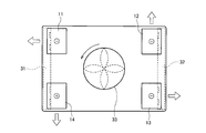
- the arrows indicate the direction in which air is blown out from the air outlets 11-14.
- the outer side in the longitudinal direction of the ion generation unit 100 is obtained by the inclined surface 201 a as the inner wall of the ventilation wall 201, the inclined surface 202 b of the ventilation plate 202, and the inclination of the partition plate provided at the air outlet 11. Air containing negative ions is diffused toward (leftward in FIG. 18).
- ions are generated by the inclined surface 201 a as the inner wall of the ventilation wall 201, the inclined surface 202 a of the ventilation plate 202, the rectifying plates 204 and 204, and the inclination of the partition plate provided at the air outlet 12.
- Air containing positive ions is diffused toward the outside in the short direction of unit 100 (upward in FIG. 18).
- an outer side in the longitudinal direction of the ion generation unit 100 is obtained by the inclined surface 201 a as the inner wall of the ventilation wall 201, the inclined surface 202 b of the ventilation plate 202, and the inclination of the partition plate provided at the air outlet 13. Air containing negative ions is diffused toward (in the right direction in FIG. 18).
- ions are generated by the inclined surface 201 a as the inner wall of the ventilation wall 201, the inclined surface 202 a of the ventilation plate 202, the rectifying plates 204 and 204, and the inclination of the partition plate provided at the air outlet 14. Air containing positive ions is diffused toward the outside in the short direction of unit 100 (downward in FIG. 18).
- the ion generating unit 100 is provided with a plurality of air outlets 11 to 14 on the same plane as the air inlet 15 and around the air inlet 15.
- the air sucked from the air suction port 15 disposed in the center portion becomes air containing ions inside the ion generation unit 100, and a plurality of air outlets provided around the air suction port 15. Since it is blown out from 11 to 14, the diffusibility of ions can be improved.
- the plurality of air outlets 11 to 14 are provided. Ions can be efficiently diffused indoors or in the vehicle 1000.
- the air outlets 11 to 14 are provided in the same plane as the air inlet 15, for example, when the ion generating unit 100 is installed on the ceiling or wall, or on the inner upper wall surface of the vehicle 1000 (FIG. 1).
- the air outlets 11 to 14 and the air suction port 15 can be flush with the ceiling surface or wall surface, eliminating the restriction that the ion generating unit must be installed in a state where it protrudes from the ceiling surface or wall surface. Can look good.
- the blowing direction along the same plane of the air blown out from each of the air blowing ports 11 to 14 can be set to different directions equally.
- the air outlets 11 to 14 are arranged at the positions of the four corners of the rectangle, and the direction of the air blown from each air outlet 11 to 14 is substantially the same as the blowing direction from the adjacent air outlet. Make a right angle.
- ions can be evenly diffused in four directions from the mounting surface of the air outlets 11 to 14 of the ion generating unit 100.
- the ion generation unit 100 is provided with a fan 33 inside the air passage.
- the fan 33 has blades that rotate around an axis orthogonal to the surfaces of the air outlets 11 to 14 and the air inlet 15.
- the air sucked from the air suction port 15 is blown out from the air outlets 11 to 14 through the ventilation path R.
- the direction of blowing from each of the air outlets 11 to 14 (the direction of the arrow (white) shown in FIG. 18) so as to coincide with the rotation direction of the blades (the direction of the arrow (solid line) shown in FIG. 18).
- the blowing direction is set so that the blowing directions from the air outlets 11 to 14 are counterclockwise. Thereby, air containing ions can be blown out against the flow of spiral air generated by the rotation of the fan 33, and ion diffusibility can be improved.
- FIGS. 7 to 18 When the ion generation unit 100 shown in FIGS. 7 to 18 is attached to the vehicle 1000 as shown in FIGS. 2 and 3 (first embodiment), as shown in FIGS. 4 and 5
- a simulation was performed on the ion concentration distribution created by the ions blown from the ion generation unit 100.
- FIG. 19 shows a simulation result according to the first embodiment
- FIG. 20 shows a simulation result according to the second embodiment. 19 and 20 show a plane having a height of 1.2 m (the breathing height of a person sitting on a seat) from the floor of the vehicle in one vehicle.
- the height difference of the speed of the airflow (arrow A shown in FIGS. 3 and 5) blown out from the air-conditioning air outlet 500 was set to 2.25 m / s.
- six ion generating units 100 were installed in one vehicle. The amount of ions blown from each ion generation unit 100 was set to 2 million / cm 3 . Air containing both positive ions and negative ions is blown out from each of the air outlets 11 to 14 of each ion generation unit 100.
- the H region (the densely hatched region) indicates a region having an ion concentration of 20000 / cm 3 or more
- the M region (the sparsely hatched region) has an ion concentration of 15000 / A region that is greater than or equal to cm 3 is shown
- an L region (without hatching) is a region that has an ion concentration of less than 15000 ions / cm 3 .
- a region in which a high concentration of ions exists in a relatively wide range in the vehicle 1000 (region H having an ion concentration of 20000 / cm 3 or more) can be formed. .
- the height difference of the ion concentration in the vehicle 1000 can be created in a relatively wide range.
- the bactericidal action due to the high concentration of ions can be more effectively exhibited in a wide range.
- two ion generators 100 are provided with an air-conditioning air outlet 500, that is, a plurality of slit-shaped hole groups arranged in two rows. Are arranged so as to face each other in a direction slightly intersecting with the longitudinal direction of the vehicle 1000.
- a plurality of ion generators 100 are arranged side by side in the longitudinal direction of the vehicle 1000 at intervals. All the ion generators 100 are arranged so as to be positioned right above the seat 700.
- Other configurations in the third embodiment of the vehicle 1000 are the same as those in the first embodiment. It should be noted that the form shown in FIG. 6 is also adopted for the form of air-conditioning air outlet 500 in the third embodiment, as in the first and second embodiments.
- FIGS. 7 to 18 When the ion generation unit 100 shown in FIGS. 7 to 18 is attached to the vehicle 1000 as shown in FIGS. 21 and 22 (third embodiment), the ions are blown out from the ion generation unit 100. A simulation was performed on the ion concentration distribution produced.
- FIG. 23 shows the simulation result according to the third embodiment.
- FIG. 23 shows a plane having a height of 1.2 m (the breathing height of a person sitting on a seat) from the floor of the vehicle in one vehicle.
- the height difference of the speed of the airflow (A arrow shown in FIG. 22) blown out from the air-conditioning air outlet 500 was set to 2.25 m / s.
- six ion generating units 100 were installed in one vehicle. The amount of ions blown from each ion generation unit 100 was set to 2 million / cm 3 . Air containing both positive ions and negative ions is blown out from each of the air outlets 11 to 14 of each ion generation unit 100.
- an H region indicates a region where the ion concentration is 20000 / cm 3 or more
- an M region region where hatching is sparse
- the region of L indicates a region where the ion concentration is less than 15000 / cm 3 .
- a region H) having a concentration of 20000 / cm 3 or more can be formed. Thereby, the height difference of the ion concentration in the vehicle 1000 can be created in a relatively wide range. As a result, the bactericidal action by high concentration ions can be effectively exhibited in a relatively wide range in the vehicle.
Landscapes
- Engineering & Computer Science (AREA)
- Mechanical Engineering (AREA)
- Air-Conditioning For Vehicles (AREA)
- Disinfection, Sterilisation Or Deodorisation Of Air (AREA)
Abstract
イオン発生器の設置台数を増やすことなく、車両内のイオン濃度を高めることが可能な車両を提供する。車両(1000)は複数の空調用空気吹き出し口(500)とイオン発生装置(100)の空気吹き出し口とを備える。複数の空調用空気吹き出し口(500)のうち、空調用空気吹き出し口(500)から吹き出される気流がイオン発生装置(100)の空気吹き出し口から吹き出される気流と交差または近接するように配置されている空調用空気吹き出し口(500)においては、当該空調用空気吹き出し口(500)から吹き出される気流の速度を他の空調用空気吹き出し口(500)から吹き出される気流の速度よりも低くするように、複数の空調用空気吹き出し口(500)が構成されている。
Description
この発明は、一般的には、車両に関し、特定的には、車両内の空気を調整するために空気を吹き出す吹き出し口を備えた鉄道車両、バスなどの車両に関するものである。
鉄道車両、バスなどの各種の車両内には、汚れた外気に曝された乗客が出入りする。そして、車両に乗り込む乗客は、外気に含まれる菌、花粉、ほこりなどを車両内に持ち込んでしまうことが多い。特に、雨の日などは、車両に乗り込む乗客の靴、傘などが、濡れた状態のままで車両内に持ち込まれる。このため、車両内の床面は、菌、花粉、ほこりなどと雨水とが溜まった状態になる。
菌、花粉、ほこりなどは、目に見えない微小なものであって、通常は空気中を浮遊しながら移動するものである。そして、菌、花粉、ほこりなどは、時間の経過と共に自然落下して、最終的に床面または地面にまで落ちていく。そのため、車両の床面付近は、菌、花粉、ほこりなどが非常に多い状態となっている。車両内の環境条件にもよるが、落下した後の菌は繁殖しやすく、車両内の床面には多数の菌が生息していることがある。特に、雨の日は車両内の床面も濡れていることが多いため、雨の日の車両内の床面は菌の繁殖に絶好のコンディションとなってしまう。
以上のように、車両内の床面および床面付近には、菌、花粉、ほこりなどが多く存在している。これらの菌などが車両に乗り込む乗客に付着するなどして、乗客に悪影響を及ぼす可能性が非常に高くなっている。
これらの問題を解決するために、特開2006-69427号公報(以下、特許文献1という)では、イオン制御車輌が提案されている。イオン制御車輌は、複数の椅子と、複数の椅子のいずれかの背面からイオンを放出する正負イオン発生器と、複数の椅子のいずれかの向きを変更する回転軸と、回転軸が変更した椅子の向きを検出する向きセンサと、椅子の向きを比較することにより、複数の椅子のいずれかである第1の椅子が、第1の椅子の正面にあって正負イオン発生器がイオンを放出する第2の椅子の背面に面するか否かを判断し、自らが、第1の椅子が第2の椅子の背面に面すると判断した場合、第2の椅子の背面からイオンを放出するように、正負イオン発生器を制御する制御部と、走行する走行部とを含む。
しかし、特許文献1で開示されているイオン制御車輌は、座席の背面からイオンを放出し、そのイオンによって菌などを除去するものである。この場合、放出されたイオンは、座席座面より高い部分には届きやすいが、菌などが最も多く存在している(繁殖している)床面付近には届かない可能性がある。すなわち、座席に座っている乗客にはイオンが到達するが、菌などの繁殖源となる床面に到達するイオンは少なく、菌などを除去する効果は小さい。また、特許文献1で開示されているイオン制御車輌は、新幹線などのように座席が進行方向に並べられている鉄道車両には適応できるが、在来線などのように座席が左右方向に向き合って並べられている鉄道車両には適応できない、という問題がある。
これらの問題を解決するために、特開2009-126349号公報(以下、特許文献2という)では、座席の下部にイオン発生器を備えた車両が提案されている。この車両は、第1の座席と第2の座席とを含む複数の座席が配置される車両である。第1の座席は、第1の座席下部に配置され、正負イオンを発生させる第1の正負イオン発生器と、第1の正負イオン発生器と連通される第1の吸い込み口と、第1の座席下部に形成され、第1の正負イオン発生器と連通される第1の吹き出し口と、第1の吸い込み口から第1の吹き出し口までの経路上に配置され、第1の吸い込み口から第1の吹き出し口へと空気を送る第1の送風機とを備える。第2の座席は、第2の座席下部に配置され、正負イオンを発生させる第2の正負イオン発生器と、第2の座席下部に形成され、第2の正負イオン発生器と連通される第2の吸い込み口と、第2の座席下部に形成され、第2の正負イオン発生器と連通される第2の吹き出し口と、第2の吸い込み口から第2の吹き出し口までの経路上に配置され、第2の吸い込み口から第2の吹き出し口へと空気を送る第2の送風機とを備える。第1の吹き出し口は、第2の吸い込み口に向けて開口される。
特許文献2に開示されている車両によれば、菌、花粉、ほこりなどが多く存在している床面および床面付近に、正負イオン発生器にて発生した正負イオンを多く含んだ空気を一様に供給することができる。そして、正負イオン発生器にて発生させられた正負イオンを多く含む空気によって、第1の座席と第2の座席との間の床面および床面付近の菌、花粉、ほこり等を除去または不活化する。その結果、効率的に車両内の空気の浄化を行うことができる。また、特許文献2に開示されている車両は、新幹線などのように座席が進行方向に並べられている鉄道車両にも、在来線などのように座席が左右方向に向き合って並べられている鉄道車両にも適応できる。
ところで、特許文献1に開示されているイオン制御車両では、各座席の背面にイオン発生器が設けられている。また、特許文献2に開示されている車両では、各座席の下部にイオン発生器が備えられている。このため、特許文献1と特許文献2に開示されている車両では、車両内の全体にイオンを行き渡らせるためには、すべての座席にイオン発生器を設ける必要があり、イオン発生器の設置台数が多くなるので、コストが高くなる、という問題がある。
各座席ではなく、車両の内側上壁面または網棚にイオン発生器を設けることが考えられる。この場合、空気調和機の空気吹き出し口が車両の内側上壁面に設けられ、その空気吹き出し口から真下方向に空調用空気が吹き出されると、イオン発生器から吹き出されるイオンを含む空気が、空調用空気の気流に遮られる。このため、イオン発生器から吹き出される高濃度のイオンを車両内の座席に座った人に行き渡らせることができない。
また、上記のイオン発生器から吹き出される高濃度のイオンを空調用空気に含ませることが考えられる。この場合、イオンが車両内に均一に拡散する。このため、車両内の全体のイオン濃度が低くなってしまう。
したがって、車両の内側上壁面または網棚にイオン発生器を設ける場合でも、車両内のイオン濃度を高めるためには、イオン発生器の設置台数を増やす必要があるので、コストが高くなる、という問題がある。
そこで、この発明の目的は、イオン発生器の設置台数を増やすことなく、車両内のイオン濃度を高めることが可能な車両を提供することである。
この発明に従った車両は、複数の第1の吹き出し口と、複数の第2の吹き出し口とを備える。複数の第1の吹き出し口は、内壁面に設けられ、車両内の空気を調整するために空気を吹き出す。複数の第2の吹き出し口は、内壁面に設けられ、イオンを含む空気を吹き出す。複数の第1の吹き出し口のうち、第1の吹き出し口から吹き出される気流が第2の吹き出し口から吹き出される気流と交差または近接するように配置されている第1の吹き出し口においては、当該第1の吹き出し口から吹き出される気流の速度を他の第1の吹き出し口から吹き出される気流の速度よりも低くするように、複数の第1の吹き出し口が構成されている。
本発明の車両では、車両内の空気を調整するために複数の第1の吹き出し口から吹き出される気流の速度を一定にするのではなく、複数の第1の吹き出し口から吹き出される気流の速度に高低差を設けている。第2の吹き出し口から吹き出されるイオンを含む空気の気流は、第1の吹き出し口から吹き出される低い速度の気流と交差または近接する。このため、イオンを含む空気の気流は、空調用空気の気流に遮断されることなく、空調用空気の気流と合成されて、車両内の座席に向けられることができる。これにより、高濃度のイオンを含む空気を車両内の座席に座った人に行き渡らせることができる。したがって、イオン発生器の設置台数を増やすことなく、車両内のイオン濃度を高めることが可能になる。
本発明の車両において、複数の第1の吹き出し口が車両の内側上壁面に配置され、複数の第2の吹出口が複数の第1の吹出口の外側に位置する車両の内側上壁面に配置されることが好ましい。また、第1の吹き出し口から吹き出される気流が車両の内側上壁面から真下方向に吹き出され、第2の吹き出し口から吹き出される気流が車両の内側上壁面から斜め下方向に吹き出されることが好ましい。
このように第1と第2の吹き出し口を配置する場合に本発明の上記の作用効果をより好ましく発揮することができる。
本発明の車両において、複数の第1の吹き出し口が車両の長さ方向に並ぶように二列に配置された複数の矩形状の穴群を含むことが好ましい。また、本発明の車両は、複数の第1の吹き出し口の両側に配置された複数のイオン発生装置をさらに備えることが好ましい。この場合、複数の第2の吹き出し口が、複数のイオン発生装置からイオンを含む空気を吹き出す吹き出し口である。
このように複数の第1の吹き出し口と複数のイオン発生装置を配置する場合に本発明の上記の作用効果をより好ましく発揮することができる。
上記の場合、複数のイオン発生装置が、複数の矩形状の穴群を間に挟んで、車両の長さ方向と直交する方向に、対向するように、かつ、車両の長さ方向に間隔をあけて、配置されていることが好ましい。
このように複数のイオン発生装置を配置することにより、車両内の比較的狭い範囲で高濃度のイオンが存在する領域を形成することができる。
また、上記の場合、複数のイオン発生装置が、複数の矩形状の穴群を間に挟んで、車両の長さ方向と斜めに交差する方向に、対向するように、かつ、車両の長さ方向に間隔をあけて、配置されていることが好ましい。
このように複数のイオン発生装置を配置することにより、車両内の比較的広い範囲で高濃度のイオンが存在する領域を形成することができる。
なお、本発明の車両において、複数のイオン発生装置の各々には、イオンを含む空気をそれぞれ異なる方向に吹き出す複数の吹き出し口が設けられていることが好ましい。
このようにすることにより、イオンを含む空気をイオン発生装置から周囲に均等に拡散することができる。
この場合、複数のイオン発生装置の各々に設けられた複数の吹き出し口において隣り合う二つの吹き出し口から吹き出される空気に含まれるイオン種は、互いに異なる極性を有することが好ましい。
このようにすることにより、正イオンと負イオンとを中和させることなく、イオン発生装置から周囲に均等に拡散することができる。
この発明によれば、イオン発生器の設置台数を増やすことなく、車両内のイオン濃度を高めることが可能になる。
以下、この発明の実施の形態を図面に基づいて説明する。
(第1の実施の形態)
図1~図3に示すように、車両1000内には、進行方向に、すなわち、車両の長さ方向に複数の座席700が並んで配置されている。また、複数の座席700は、車両1000の幅方向の中央部に位置する通路を挟んで二列に配置されている。網棚600が車両1000内の両側壁面に設けられている。また、網棚600は、座席700の上に位置づけられ、二列の座席700のそれぞれの列に沿って延びるように配置されている。
複数の第1の吹き出し口の一例としての空調用空気吹き出し口500が、車両1000の内側上壁面、すなわち天井壁面に設けられている。車両1000内の空気を調整するために空気が空調用空気吹き出し口500から吹き出される。空調用空気吹き出し口500から吹き出される気流は、矢印Aで示されるように、車両1000の内側上壁面から真下方向に吹き出される。空調用空気吹き出し口500は、車両1000の長さ方向に並ぶように二列に配置されている。この実施形態では、空調用空気吹き出し口500は、車両1000の幅方向の中央部に位置する通路を挟んで二列に配置されている。また、空調用空気吹き出し口500は、二列に配置された複数の矩形状の穴群、たとえば、複数のスリット状の穴群から構成される。複数のスリット状の穴は、車両1000の長さ方向に間隔をあけて配置されている。
複数のイオン発生装置100は、空調用空気吹き出し口500の外側で両側に位置する車両1000の内側上壁面、すなわち傾斜した天井壁面に配置されている。車両1000内の空気中に存在する浮遊細菌、浮遊ウイルスなどを除去するためにイオンを含む空気がイオン発生装置100の空気吹き出し口から吹き出される。この実施形態では、4つの空気吹き出し口が、イオンを含む空気をそれぞれ異なる方向に吹き出すためにイオン発生装置100に設けられている。イオン発生装置100に設けられた4つの空気吹き出し口において隣り合う2つの空気吹き出し口から吹き出される空気に含まれるイオン種は、互いに異なる極性を有する。すなわち、この実施形態では、イオン発生装置100の周囲方向に沿って順に正イオン(+)、負イオン(-)、正イオン(+)、負イオン(-)を含む空気が、矢印で示すように、4つの空気吹き出し口から4方向に吹き出される。イオン発生装置100の空気吹き出し口から吹き出される気流は、車両1000の内側上壁面から斜め下方向に吹き出される。なお、イオン発生装置100の空気吹き出し口は、複数の第2の吹き出し口の一例である。イオン発生装置100の詳細については後述する。
この実施の形態では、図2に示すように、2つのイオン発生装置100が、空調用空気吹き出し口500、すなわち、二列に配置された複数のスリット状の穴群を間に挟んで、車両1000の長さ方向と直交する方向に、対向するように配置されている。また、複数のイオン発生装置100が、車両1000の長さ方向に間隔をあけて並んで配置されている。
以上のように構成された車両1000において、図3に示すように、複数の空調用空気吹き出し口500のうち、空調用空気吹き出し口500から吹き出される気流(Aの矢印)がイオン発生装置100の空気吹き出し口から吹き出される気流(+と-の矢印)と交差または近接するように配置されている空調用空気吹き出し口500においては、当該空調用空気吹き出し口500から吹き出される気流(Aの矢印)の速度を他の空調用空気吹き出し口500から吹き出される気流(Aの矢印)の速度よりも低くするように、複数の空調用空気吹き出し口500が構成されている。すなわち、イオン発生装置100の付近に配置されている空調用空気吹き出し口500から吹き出される気流(Aの矢印)の速度は、他の空調用空気吹き出し口500から吹き出される気流(Aの矢印)の速度よりも低い。この気流の速度の高低差については、図3では、イオン発生装置100の付近に配置されている空調用空気吹き出し口500から吹き出される気流を示すAの矢印の長さを、他の空調用空気吹き出し口500から吹き出される気流を示すAの矢印の長さよりも短くして表示されている。
このように本発明の車両1000では、車両1000内の空気を調整するために複数の空調用空気吹き出し口500から吹き出される気流の速度を一定にするのではなく、複数の空調用空気吹き出し口500から吹き出される気流の速度に高低差を設けている。イオン発生装置100の空気吹き出し口から吹き出されるイオンを含む空気の気流は、空調用空気吹き出し口500から吹き出される低い速度の気流と交差または近接する。このため、イオンを含む空気の気流は、空調用空気の気流に遮断されることなく、空調用空気の気流と合成されて、車両1000内の座席700に向けられることができる。これにより、高濃度のイオンを含む空気を車両1000内の座席700に座った人に行き渡らせることができる。したがって、イオン発生器の設置台数を増やすことなく、車両内のイオン濃度を高めることが可能になる。
また、本発明の車両1000において、複数の第1の吹き出し口としての空調用空気吹き出し口500が、車両1000の内側上壁面に配置される。複数の第2の吹き出し口としての複数のイオン発生装置100の空気吹き出し口が、複数の空調用空気吹き出し口500の外側に位置する車両1000の内側上壁面に配置される。また、空調用空気吹き出し口500から吹き出される気流が、車両1000の内側上壁面から真下方向に吹き出される。イオン発生装置100の空気吹き出し口から吹き出される気流が、車両1000の内側上壁面から斜め下方向に吹き出される。
このように空調用空気吹き出し口500とイオン発生装置100の空気吹き出し口を配置する場合に本発明の上記の作用効果をより好ましく発揮することができる。
本発明の車両1000において、複数の空調用空気吹き出し口500が車両1000の長さ方向に並ぶように二列に配置された複数の矩形状の穴群を含む。また、本発明の車両1000は、複数の空調用空気吹き出し口500の両側に配置された複数のイオン発生装置100を備える。
このように複数の空調用空気吹き出し口500と複数のイオン発生装置100を配置する場合に本発明の上記の作用効果をより好ましく発揮することができる。
この実施形態の場合、複数のイオン発生装置100が、複数の空調用空気吹き出し口500、すなわち複数の矩形状の穴群を間に挟んで、車両1000の長さ方向と直交する方向に、対向するように、かつ、車両1000の長さ方向に間隔をあけて、配置されている。
このように複数のイオン発生装置100を配置することにより、車両1000内の比較的狭い範囲で高濃度のイオンが存在する領域を形成することができる。これにより、車両1000内にイオン濃度の高低差を比較的狭い範囲で作り出すことができる。その結果、高濃度のイオンによる殺菌作用を狭い範囲で効果的に発揮させることができる。
なお、イオンによる殺菌効果、すなわち、イオンによって浮遊細菌、浮遊ウイルスなどを除去する効果は、イオンの濃度に依存する。イオン濃度が高ければ高いほど、その効果が高い。たとえば、浮遊ウイルスの除去性能でいえば、イオン濃度が7000個/cm3の場合には10分間で浮遊ウイルスの残存率が1/100になるのに対し、イオン濃度が50000個/cm3の場合には10分間で浮遊ウイルスの残存率が1/1000になる。また、衣服等に付着したタバコの臭いの脱臭効果は、イオン濃度が5000個/cm3の場合に比べて、イオン濃度が20000個/cm3の場合には脱臭速度が約2倍になる。
なお、本発明の車両1000において、複数のイオン発生装置100の各々には、イオンを含む空気をそれぞれ異なる方向に吹き出す複数の吹き出し口が設けられていることにより、イオンを含む空気をイオン発生装置100から周囲に均等に拡散することができる。この場合、複数のイオン発生装置100の各々に設けられた複数の空気吹き出し口において隣り合う二つの空気吹き出し口から吹き出される空気に含まれるイオン種は、互いに異なる極性を有することにより、正イオンと負イオンとを中和させることなく、イオン発生装置100から周囲に均等に拡散することができる。
(第2の実施の形態)
車両1000の第2の実施の形態は、図4と図5に示される。この実施形態では、第1の実施形態と異なり、図4に示すように、2つのイオン発生装置100が、空調用空気吹き出し口500、すなわち、二列に配置された複数のスリット状の穴群を間に挟んで、車両1000の長さ方向と斜めに交差する方向に、対向するように配置されている。また、複数のイオン発生装置100が、車両1000の長さ方向に間隔をあけて並んで配置されている。車両1000の第2の実施の形態における他の構成は、第1の実施の形態と同様である。
このように複数のイオン発生装置100を配置することにより、車両1000内の比較的広い範囲で高濃度のイオンが存在する領域を形成することができる。これにより、車両1000内にイオン濃度の高低差を比較的広い範囲で作り出すことができる。その結果、高濃度のイオンによる殺菌作用を、第1の実施の形態に比べて、広い範囲でより効果的に発揮させることができる。
なお、車両1000の第2の実施の形態においても、第1の実施の形態と同様の作用効果を得ることができる。
(空調用空気吹き出し口の形態)
上記の第1と第2の実施の形態では、図3と図5に示すように、複数の空調用空気吹き出し口500のうち、空調用空気吹き出し口500から吹き出される気流(Aの矢印)がイオン発生装置100の空気吹き出し口から吹き出される気流(+と-の矢印)と交差または近接するように配置されている空調用空気吹き出し口500においては、当該空調用空気吹き出し口500から吹き出される気流(Aの矢印)の速度を他の空調用空気吹き出し口500から吹き出される気流(Aの矢印)の速度よりも低くするように、複数の空調用空気吹き出し口500が構成されている。このようにするための複数の空調用空気吹き出し口500の形態について以下に説明する。
図6の(A)に示すように、吹き出される気流の速度が高い空調用空気吹き出し口500では、気流が通過する通路は周側壁部510のみによって形成されている。この場合、周側壁部510によって囲まれた通路を通過する気流の全部が空調用空気吹き出し口500から吹き出されるので、吹き出される気流の速度(風量)が大きい。
これに対して、図6の(B)に示すように、吹き出される気流の速度が低い空調用空気吹き出し口500では、気流が通過する通路は複数の小さな吹き出し穴520と、周側壁部510で囲まれた通路を区分して複数の吹き出し穴520を形成するための遮断壁部530とが形成されている。この場合、周側壁部510によって囲まれた通路を通過する気流の一部が遮断壁部530によって遮られ、気流の一部が小さな吹き出し穴520から吹き出されるので、吹き出される気流の速度(風量)が小さくなる。
(イオン発生装置の実施の形態)
上記の第1と第2の実施の形態の車両1000に設けられるイオン発生装置(イオン発生ユニット)100の一つの実施の形態について、図7~図18を参照して、以下に説明する。
図7と図8に示すように、イオン発生ユニット100は、一面が開口した箱状のケース40、ケース40に収容される一面が開口した箱状の本体ベース30、本体ベース30の上面(前面)に取り付けられる吸込グリル20、吸込グリル20の上面(前面)に取り付けられる空気案内板としての前面パネル10などを備えている。
イオン発生ユニット100の前面パネル10には、中央部に空気吸込口15が設けられている。空気吸込口15と同一面上であって、空気吸込口15を囲むように、空気吹出口11、12、13、14が設けられている。ここで、同一面とは、本実施の形態で例示するように、空気吸込口と空気吹出口とが同一平面にある場合のみならず、同一の屈曲面にある場合(たとえば、空気吸込口の開口面の法線方向と空気吹出口の開口面の法線方向とが鋭角をなすように互いに傾いて設けられているような場合)、互いに平行な平面にある場合(たとえば、空気吸込口の開口面と空気吹出口の開口面とが段差を有して設けられている場合)などを含むものとする。空気吹出口11~14は、空気吸込口15を囲んで長方形の略四隅に配置されている。また、空気吸込口15の裏面には、略同寸法のフィルタ(図示せず)を取り付けることができる。これにより、空気中の塵を除去することができる。
図8に示すように、吸込グリル20の前面(上面)には、空気吸込口15に対応する位置に略同寸法の吸込孔25が設けられている。空気吹出口11~14のそれぞれに対応する位置に略同寸法の吹出孔21、22、23、24が設けられている。
また、図8と図9に示すように、本体ベース30には、イオン発生素子31、32、羽根を備えたファン33、イオン発生ユニット100を制御する制御部35、LEDを備える表示部36などが取り付けられている。
図9に示すように、本体ベース30は、中央部にファン33が取り付けられるように構成されている。本体ベース30の底面であって、ファン33が取り付けられる箇所には、外側から内側に向かって円形状に絞り込んだ椀状の絞り部37が形成されている。ファン33が動作することにより、空気吸込口15から吸い込まれた空気の流れが本体ベース30の底面に当たる際に、絞り部37により、吸い込まれた空気を本体ベース30の底面に沿ってスムーズに流れやすくすることができ、空気流の乱れを生じさせることなく、吸い込まれた空気を空気吹出口11~14へ導くことができる。
本体ベース30の対向する1組の側壁同士は、前面(上面)に向かって拡がるように傾斜するように形成されている。それぞれの側壁にイオン発生素子31、32が取り付けられている。イオン発生素子31、32は、先端に係止部が形成された固定板34により側壁に押圧されて取り付けられる。なお、イオン発生素子31、32は、固定板34により着脱可能に取り付けられるようになっている。
イオン発生素子31は矩形状の板状体である。イオン発生素子31の一方の端部近傍には、マイナスイオンを発生させる電極部としての電極針31a、31bが適度の長さで離隔して設けられている。イオン発生素子31の他方の端部近傍には、プラスイオンを発生させる電極部としての電極針31c、31dが適度の長さで離隔して設けられている。イオン発生素子31を取り付けた状態で、吹出孔21および空気吹出口11の近傍には、マイナスイオンを発生するイオン発生電極部が配置されている。マイナスイオンを含む空気が吹出孔21および空気吹出口11から吹き出される。また、イオン発生素子31を取り付けた状態で、吹出孔24および空気吹出口14の近傍には、プラスイオンを発生するイオン発生電極部が配置されている。プラスイオンを含む空気が吹出孔24および空気吹出口14から吹き出される。
イオン発生素子32は、イオン発生素子31と同様の構成を有する。イオン発生素子32を取り付けた状態で、吹出孔22および空気吹出口12の近傍には、プラスイオンを発生するイオン発生電極部が配置されている。プラスイオンを含む空気が吹出孔22および空気吹出口12から吹き出される。また、イオン発生素子32を取り付けた状態で、吹出孔23および空気吹出口13の近傍には、マイナスイオンを発生するイオン発生電極部が配置されている。マイナスイオンを含む空気が吹出孔23および空気吹出口13から吹き出される。
イオン発生素子31、32は、空気中の水蒸気をプラズマ放電によりイオン化することにより、プラスイオンとしてのH+(H2O)n(nは任意の自然数)と、マイナスイオンとしてのO2
-(H2O)m(mは任意の自然数)とを発生する。そして、これらが化学反応することにより、活性種である過酸化水素(H2O2)および/または水酸基ラジカル(OH)が生成され、空気中の浮遊細菌、浮遊ウィルス等が除去される。
以上のように構成されているので、それぞれの空気吹出口11~14は、独立にプラスイオンを含む空気、あるいはマイナスイオンを含む空気を吹き出すことができ、イオン発生ユニット100から吹き出した空気中のプラスイオンとマイナスイオンとが直ちに中和することを防止できる。そして、イオンの中和を防止することにより、イオンの拡散性を向上させることができる。
また、表示部36は、イオン発生ユニットの動作状態(たとえば、運転または停止の別、発生するイオン濃度の高低など)をLEDの点灯状態で示す。また、制御部35は、イオン発生ユニット100の全体の動作を制御するマイクロコンピュータ、イオン発生素子31、32とファン33に供給する所定の電圧を発生する電源回路、前面パネル10の着脱を検出するためのマイクロスイッチ351などを備えている。
図10に示すように、前面パネル10の裏面側に立てて設けられた突起棒16がマイクロスイッチ351を押すことにより、マイクロスイッチ351はオンとなり、前面パネル10が装着されていることを検出する。一方、前面パネル10が外れた場合、突起棒16がマイクロスイッチ351から離れ、マイクロスイッチ351がオフして前面パネル10が離脱したことを検出する。前面パネル10が離脱した場合、マイクロスイッチ351がオフしてイオン発生ユニット100の動作は停止または運転できない状態になる。
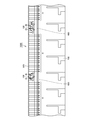
図10に示すように、吸込グリル20の裏面側(後面側)には、吸込孔25を挟むようにして本体ベース30の深さ寸法より短い寸法の深さ(高さ)を有する吹出方向設定部材としての通気壁201、201を対向するように設けられている。すなわち、本体ベース30に吸込グリル20を取り付けた状態で、本体ベース30の底面内側と通気壁201との間には、ファン33で吸い込まれた空気が流れるのに必要な十分な隙間が設けられている。
通気壁201の吹出孔21~24側の側壁は、深さ(高さ)方向に沿ってテーパー状になった吹出方向設定部材としての傾斜面(内壁)201aを有する。また、通気壁201の中央部には、吹出方向設定部材としての通気板202が吹出孔22、23に挟まれるように設けられている。通気板202は、通気壁201と略同寸法の深さ(高さ)を有する。通気板202の吹出孔22、23側の側面は、深さ(高さ)方向に沿ってテーパー状になった吹出方向設定部材としての傾斜面(内壁)202a、202bを有する。なお、吹出孔21、24側の通気板202も同様の構成を有する。
本体ベース30に吸込グリル20を取り付けた状態で、通気壁201と通気板202は、本体ベース30の内壁(底面内側、側面内側等)とともに、空気吸込口15と空気吹出口11~14とを連通する通気路R(図15)を形成する。そして、通気路Rには、ファン33の羽根の回転軸が空気吸込口15および空気吹出口11~14の面と直交するようにファン33が取り付けられている。
また、図10と図13に示すように、吹出孔22の裏側には、空気の吹き出し方向を設定するための吹出方向設定部材としての整流板204、204が傾斜面202aと略平行に適度な長さで離隔して設けられている。吹出孔24の裏側にも、同様に空気の吹き出し方向を設定するための整流板204、204が傾斜面202aと略平行に適度な長さで離隔して設けられている。
図14はイオン発生ユニット100の長手方向から見た状態を示し、図15はイオン発生ユニット100の短手方向から見た状態を示す。図14に示すように、ファン33を動作させることにより、空気吸込口15から空気が吸い込まれる。吸い込まれた空気は、ファン33を介して通気路Rを通り、空気吹出口13、14(空気吹出口11、12は図14では図示せず)から吹出される。なお、図14において矢印は空気の流れを示す。空気吹出口13から吹き出される際に、イオン発生素子32のマイナスイオン発生電極部で発生したマイナスイオンが空気に含まれ、マイナスイオンを含む空気が吹き出される。また、空気吹出口14から吹き出される際に、イオン発生素子31のプラスイオン発生電極部で発生したプラスイオンが空気に含まれ、プラスイオンを含む空気が吹き出される。
また、通気路Rの内壁である傾斜面201aにより、空気吹出口13、14から吹き出される空気は、傾斜面201aに沿った方向(傾斜面201aと平行な方向)へ拡散する。なお、傾斜面201aと空気吹出口13、14の面とのなす角度は、たとえば、45度程度が好ましいが、これに限定されるものではなく、30度~60度程度でもよい。
また、図15に示すように、ファン33を動作させることにより、空気吸込口15から空気が吸い込まれる。吸い込まれた空気は、ファン33を介して通気路Rを通り、空気吹出口12、13(空気吹出口11、14は図15では図示せず)から吹出される。なお、図15において矢印は空気の流れを示す。空気吹出口12から吹き出される際に、イオン発生素子32のプラスイオン発生電極部で発生したプラスイオンが空気に含まれ、プラスイオンを含む空気が吹き出される。
また、通気路Rの内壁である傾斜面202a、202bにより、空気吹出口12、13から吹き出される空気は、それぞれ傾斜面202a、202bに沿った方向(傾斜面202a、202bと平行な方向)へ拡散する。なお、傾斜面202a、202bと空気吹出口12、13の面とのなす角度は、たとえば、45度程度が好ましいが、これに限定されるものではなく、30度~60度程度でもよい。なお、図14と図15では、整流板204を省略している。
図16と図17に示すように、前面パネル10の空気吹出口11は、複数の吹出方向設定部材としての仕切板111を開口部112内に並べて配置することにより、スリット状に形成されている。これにより、空気吹出口11は、空気案内板としての機能を有する。また、図17に示すように、仕切板111は、空気吹出口11の吹出方向に沿って傾斜するように形成されている。傾斜した仕切板111により、図17の矢印に示すように、空気の吹出方向を設定することができる。たとえば、空気吹出口11が設けられた面に対して仕切板111を直角に設けるのではなく、当該面に対して所定の傾斜角(たとえば、45度等)で傾斜させることによって、イオンを含む空気の吹出方向を仕切板111の傾きに応じて空気吹出口11から斜めにすることができる。これにより、イオンの拡散性をさらに高めることができる。他の空気吹出口12~14も同様の構成を有する。
図18において、矢印は、空気吹出口11~14からの空気の吹き出し方向を示す。空気吹出口11については、通気壁201の内壁としての傾斜面201a、通気板202の傾斜面202b、および、空気吹出口11に設けられた仕切板の傾きにより、イオン発生ユニット100の長手方向外側(図18にて左方向)に向かってマイナスイオンを含む空気が拡散される。
空気吹出口12については、通気壁201の内壁としての傾斜面201a、通気板202の傾斜面202a、整流板204、204、および、空気吹出口12に設けられた仕切板の傾きにより、イオン発生ユニット100の短手方向外側(図18にて上方向)に向かってプラスイオンを含む空気が拡散される。
空気吹出口13については、通気壁201の内壁としての傾斜面201a、通気板202の傾斜面202b、および、空気吹出口13に設けられた仕切板の傾きにより、イオン発生ユニット100の長手方向外側(図18にて右方向)に向かってマイナスイオンを含む空気が拡散される。
空気吹出口14については、通気壁201の内壁としての傾斜面201a、通気板202の傾斜面202a、整流板204、204、および、空気吹出口14に設けられた仕切板の傾きにより、イオン発生ユニット100の短手方向外側(図18にて下方向)に向かってプラスイオンを含む空気が拡散される。
このように、イオン発生ユニット100には、空気吹出口11~14が、空気吸込口15と同一平面に、かつ、空気吸込口15の周りに複数設けられている。これにより、中央部に配置された空気吸込口15から吸い込まれた空気は、イオン発生ユニット100の内部でイオンを含む空気となって、空気吸込口15の周りに設けられた複数の空気吹出口11~14より吹き出されるので、イオンの拡散性を向上させることができる。特に、イオン発生ユニット100を、室内の天井または壁、あるいは、車両1000(図1)の内側上壁面に取り付けた場合であっても、複数の空気吹出口11~14が設けられているので、イオンを室内あるいは車両1000内に効率的に拡散することができる。
また、空気吹出口11~14が空気吸込口15と同一平面に設けられているので、たとえば、イオン発生ユニット100を天井または壁、あるいは、車両1000(図1)の内側上壁面に設置する場合に、空気吹出口11~14および空気吸込口15を天井面または壁面と同一面にすることができ、イオン発生ユニットが天井面または壁面から飛び出した状態で設置しなければならないという制約を排除することができ、見た目も良くなる。
また、図18に示すように、各空気吹出口11~14から吹き出された空気の同一平面に沿った吹出方向をそれぞれ均等に異なる方向へ設定することができる。図18の例では、一例として、空気吹出口11~14を長方形の各四隅の位置に配置し、各空気吹出口11~14から吹き出す空気の方向を隣接する空気吹出口からの吹出方向と略直角をなすようにする。これにより、イオン発生ユニット100の空気吹出口11~14の取り付け面から四方に均等にイオンを拡散することができる。
また、イオン発生ユニット100には、ファン33が通気路の内側に設けられている。ファン33は、空気吹出口11~14および空気吸込口15の面と直交する軸の周りに回転する羽根を有する。ファン33を作動させることにより、空気吸込口15から吸い込まれた空気は、通気路Rを通って空気吹出口11~14から吹き出される。そして、羽根の回転方向(図18で示される矢印(実線)の方向)と一致するように、各空気吹出口11~14からの吹出方向(図18に示される矢印(白抜き)の方向)が設定されている。たとえば、図18に示すように、ファン33の回転方向が反時計回りである場合、各空気吹出口11~14からの吹出方向が反時計回りになるように吹出方向を設定する。これにより、ファン33の回転により生じる渦状の空気の流れに逆らうことなく、イオンを含む空気を吹き出すことができ、イオンの拡散性を向上させることができる。
(イオン濃度分布のシミュレーション結果)
図7~図18に示されるイオン発生ユニット100を、図2と図3に示されるように車両1000に取り付けた場合(第1の実施の形態)と、図4と図5に示されるように車両1000に取り付けた場合(第2の実施の形態)について、イオン発生ユニット100から吹き出されるイオンによって作り出されるイオン濃度分布についてシミュレーションを行った。第1の実施の形態によるシミュレーション結果を図19に示し、第2の実施の形態によるシミュレーション結果を図20に示す。図19と図20は、一つの車両内において車両の床面から高さ1.2m(座席に座った人の呼吸高さ)の平面を示す。
なお、空調用空気吹き出し口500から吹き出される気流(図3と図5に示されるAの矢印)の速度の高低差を2.25m/sと設定した。図19と図20に示すように、一つの車両内に6台のイオン発生ユニット100を設置した。各イオン発生ユニット100から吹き出されるイオン量を200万個/cm3と設定した。プラスイオンとマイナスイオンの両方を含む空気が、各イオン発生ユニット100の空気吹出口11~14のそれぞれから吹き出されるものとした。
図19と図20において、Hの領域(ハッチングが密の領域)はイオン濃度が20000個/cm3以上である領域を示し、Mの領域(ハッチングが疎の領域)はイオン濃度が15000個/cm3以上である領域を示し、Lの領域(ハッチングなし)はイオン濃度が15000個/cm3未満である領域を示す。
図19に示すように、車両1000内の比較的狭い範囲で高濃度のイオンが存在する領域(イオン濃度が20000個/cm3以上である領域H)を形成することができる。これにより、車両1000内にイオン濃度の高低差を比較的狭い範囲で作り出すことができる。その結果、高濃度のイオンによる殺菌作用を狭い範囲で効果的に発揮させることができる。
これに対して、図20に示すように、車両1000内の比較的広い範囲で高濃度のイオンが存在する領域(イオン濃度が20000個/cm3以上である領域H)を形成することができる。これにより、車両1000内にイオン濃度の高低差を比較的広い範囲で作り出すことができる。その結果、高濃度のイオンによる殺菌作用を広い範囲でより効果的に発揮させることができる。
(第3の実施の形態)
車両1000の第3の実施の形態は、図21と図22に示される。この実施形態では、第1の実施形態と異なり、図21に示すように、2つのイオン発生装置100が、空調用空気吹き出し口500、すなわち、二列に配置された複数のスリット状の穴群を間に挟んで、車両1000の長さ方向とやや斜めに交差する方向に、対向するように配置されている。また、複数のイオン発生装置100が、車両1000の長さ方向に間隔をあけて並んで配置されている。全てのイオン発生装置100は座席700の真上に位置づけられるように配置されている。車両1000の第3の実施の形態における他の構成は、第1の実施の形態と同様である。なお、第3の実施の形態における空調用空気吹き出し口500の形態についても、第1と第2の実施の形態と同様にして、図6に示される形態が採用される。
このように複数のイオン発生装置100を配置することにより、車両1000内の比較的広い範囲で高濃度のイオンが存在する領域を形成することができる。これにより、車両1000内にイオン濃度の高低差を比較的広い範囲で作り出すことができる。その結果、高濃度のイオンによる殺菌作用を、第1の実施の形態に比べて、広い範囲でより効果的に発揮させることができる。
なお、車両1000の第3の実施の形態においても、第1の実施の形態と同様の作用効果を得ることができる。
(イオン濃度分布のシミュレーション結果)
図7~図18に示されるイオン発生ユニット100を、図21と図22に示されるように車両1000に取り付けた場合(第3の実施の形態)について、イオン発生ユニット100から吹き出されるイオンによって作り出されるイオン濃度分布についてシミュレーションを行った。第3の実施の形態によるシミュレーション結果を図23に示す。図23は、一つの車両内において車両の床面から高さ1.2m(座席に座った人の呼吸高さ)の平面を示す。
なお、空調用空気吹き出し口500から吹き出される気流(図22に示されるAの矢印)の速度の高低差を2.25m/sと設定した。図23に示すように、一つの車両内に6台のイオン発生ユニット100を設置した。各イオン発生ユニット100から吹き出されるイオン量を200万個/cm3と設定した。プラスイオンとマイナスイオンの両方を含む空気が、各イオン発生ユニット100の空気吹出口11~14のそれぞれから吹き出されるものとした。
図23において、Hの領域(ハッチングが密の領域)はイオン濃度が20000個/cm3以上である領域を示し、Mの領域(ハッチングが疎の領域)はイオン濃度が15000個/cm3以上である領域を示し、Lの領域(ハッチングなし)はイオン濃度が15000個/cm3未満である領域を示す。
図19に示される第1の実施の形態の車両におけるイオン濃度分布のシミュレーション結果に比べて、図23に示すように、車両1000内の比較的広い範囲で高濃度のイオンが存在する領域(イオン濃度が20000個/cm3以上である領域H)を形成することができる。これにより、車両1000内にイオン濃度の高低差を比較的広い範囲で作り出すことができる。その結果、高濃度のイオンによる殺菌作用を車内の比較的広い範囲で効果的に発揮させることができる。
今回開示された実施の形態はすべての点で例示であって制限的なものではないと考慮されるべきである。本発明の範囲は以上の実施の形態ではなく、請求の範囲によって示され、請求の範囲と均等の意味および範囲内でのすべての修正と変形を含むものであることが意図される。
車両内の空気を調整するために空気を吹き出す吹き出し口を備えた鉄道車両、バスなどの車両において、イオン発生器の設置台数を増やすことなく、車両内のイオン濃度を高めることが可能になる。
100:イオン発生装置(イオン発生ユニット)、500:空調用空気吹き出し口、1000:車両。
Claims (7)
- 内壁面に設けられ、車両(1000)内の空気を調整するために空気を吹き出す複数の第1の吹き出し口(500)と、
内壁面に設けられ、イオンを含む空気を吹き出す複数の第2の吹き出し口とを備え、
前記複数の第1の吹き出し口(500)のうち、前記第1の吹き出し口(500)から吹き出される気流が前記第2の吹き出し口から吹き出される気流と交差または近接するように配置されている前記第1の吹き出し口(500)においては、当該第1の吹き出し口(500)から吹き出される気流の速度を他の前記第1の吹き出し口(500)から吹き出される気流の速度よりも低くするように、前記複数の第1の吹き出し口(500)が構成されている、車両(1000)。 - 前記複数の第1の吹き出し口(500)が車両(1000)の内側上壁面に配置され、前記複数の第2の吹出口が前記複数の第1の吹出口(500)の外側に位置する車両(1000)の内側上壁面に配置され、前記第1の吹き出し口(500)から吹き出される気流が車両(1000)の内側上壁面から真下方向に吹き出され、前記第2の吹き出し口から吹き出される気流が車両(1000)の内側上壁面から斜め下方向に吹き出される、請求項1に記載の車両(1000)。
- 前記複数の第1の吹き出し口(500)が車両(1000)の長さ方向に並ぶように二列に配置された複数の矩形状の穴群を含み、
前記複数の第1の吹き出し口(500)の両側に配置された複数のイオン発生装置(100)をさらに備え、
前記複数の第2の吹き出し口が、前記複数のイオン発生装置(100)からイオンを含む空気を吹き出す吹き出し口である、請求項2に記載の車両(1000)。 - 前記複数のイオン発生装置(100)が、前記複数の矩形状の穴群を間に挟んで、車両(1000)の長さ方向と直交する方向に、対向するように、かつ、車両(1000)の長さ方向に間隔をあけて、配置されている、請求項3に記載の車両(1000)。
- 前記複数のイオン発生装置(100)が、前記複数の矩形状の穴群を間に挟んで、車両(1000)の長さ方向と斜めに交差する方向に、対向するように、かつ、車両(1000)の長さ方向に間隔をあけて、配置されている、請求項3に記載の車両(1000)。
- 前記複数のイオン発生装置(100)の各々には、イオンを含む空気をそれぞれ異なる方向に吹き出す複数の吹き出し口が設けられている、請求項3に記載の車両(1000)。
- 前記複数のイオン発生装置(100)の各々に設けられた前記複数の吹き出し口において隣り合う二つの吹き出し口から吹き出される空気に含まれるイオン種は、互いに異なる極性を有する、請求項6に記載の車両(1000)。
Priority Applications (3)
| Application Number | Priority Date | Filing Date | Title |
|---|---|---|---|
| US13/635,985 US20130012116A1 (en) | 2010-04-16 | 2011-03-10 | Vehicle |
| CN201180015885.7A CN102821987B (zh) | 2010-04-16 | 2011-03-10 | 车辆 |
| EP20110768687 EP2559575A1 (en) | 2010-04-16 | 2011-03-10 | Vehicle |
Applications Claiming Priority (4)
| Application Number | Priority Date | Filing Date | Title |
|---|---|---|---|
| JP2010094944 | 2010-04-16 | ||
| JP2010-094944 | 2010-04-16 | ||
| JP2010155341A JP4813614B1 (ja) | 2010-04-16 | 2010-07-08 | 車両 |
| JP2010-155341 | 2010-07-08 |
Publications (1)
| Publication Number | Publication Date |
|---|---|
| WO2011129166A1 true WO2011129166A1 (ja) | 2011-10-20 |
Family
ID=44798545
Family Applications (1)
| Application Number | Title | Priority Date | Filing Date |
|---|---|---|---|
| PCT/JP2011/055572 Ceased WO2011129166A1 (ja) | 2010-04-16 | 2011-03-10 | 車両 |
Country Status (5)
| Country | Link |
|---|---|
| US (1) | US20130012116A1 (ja) |
| EP (1) | EP2559575A1 (ja) |
| JP (1) | JP4813614B1 (ja) |
| CN (1) | CN102821987B (ja) |
| WO (1) | WO2011129166A1 (ja) |
Cited By (1)
| Publication number | Priority date | Publication date | Assignee | Title |
|---|---|---|---|---|
| CN112135743A (zh) * | 2018-05-11 | 2020-12-25 | 株式会社电装 | 流体吹出装置 |
Families Citing this family (8)
| Publication number | Priority date | Publication date | Assignee | Title |
|---|---|---|---|---|
| JP6450119B2 (ja) * | 2014-09-10 | 2019-01-09 | 川崎重工業株式会社 | 鉄道車両 |
| US9534496B1 (en) * | 2015-08-13 | 2017-01-03 | Ahmadreza Ghavami | System and method for tunnel air ventilation |
| JP6078606B1 (ja) * | 2015-09-30 | 2017-02-08 | 富士重工業株式会社 | 自動車用空調装置 |
| US20210045296A1 (en) * | 2018-01-31 | 2021-02-18 | Terracube International Inc. | Airflow system and method for a chamber |
| CN108859671B (zh) * | 2018-04-03 | 2021-08-13 | 深圳市百欧森软件技术有限公司 | 一种用于公交车的空气改良系统及方法 |
| CN109398395A (zh) * | 2018-12-07 | 2019-03-01 | 合肥中车轨道交通车辆有限公司 | 一种轨道车辆空调用空气净化器及其控制方法 |
| TW202220320A (zh) * | 2020-11-12 | 2022-05-16 | 日商夏普股份有限公司 | 送風系統 |
| JP7625402B2 (ja) * | 2020-11-12 | 2025-02-03 | 川崎車両株式会社 | 鉄道車両の空気浄化装置 |
Citations (9)
| Publication number | Priority date | Publication date | Assignee | Title |
|---|---|---|---|---|
| JPS5384811U (ja) * | 1976-12-15 | 1978-07-13 | ||
| JPS609096Y2 (ja) * | 1978-01-06 | 1985-04-01 | 株式会社日立製作所 | 客電車の天井構造 |
| JP2003170737A (ja) * | 2001-12-07 | 2003-06-17 | Toyoda Gosei Co Ltd | 自動車用空気清浄機 |
| JP2006069427A (ja) | 2004-09-03 | 2006-03-16 | Sharp Corp | イオン制御車輌 |
| JP2008202462A (ja) * | 2007-02-19 | 2008-09-04 | Sharp Corp | 送風装置、および、それを備える換気装置と空気調和機 |
| JP2009126349A (ja) | 2007-11-22 | 2009-06-11 | Sharp Corp | イオン発生器を備えた車両 |
| JP2009286196A (ja) * | 2008-05-27 | 2009-12-10 | Panasonic Electric Works Co Ltd | 脱臭・除菌機能を備えた鉄道用車両 |
| JP2009298336A (ja) * | 2008-06-16 | 2009-12-24 | Sharp Corp | 車載用イオン発生装置 |
| JP2010054076A (ja) * | 2008-08-26 | 2010-03-11 | Sharp Corp | 微小粒子拡散装置 |
Family Cites Families (5)
| Publication number | Priority date | Publication date | Assignee | Title |
|---|---|---|---|---|
| US2656779A (en) * | 1948-08-21 | 1953-10-27 | Kenworth Motor Truck Corp | Ventilation of passenger compartment of automotive buses |
| US5491602A (en) * | 1995-05-12 | 1996-02-13 | Paul Horn Enterprises, Inc. | Air distributing and ionizing systems |
| US6193603B1 (en) * | 1999-10-07 | 2001-02-27 | Kuo-Cheng Tai | Wind outlet plate of an air conditioner for cleaning air |
| US7959717B2 (en) * | 2005-12-16 | 2011-06-14 | Panasonic Electric Works Co., Ltd. | Air conditioning system with electrostatically atomizing function |
| WO2007078135A1 (en) * | 2005-12-30 | 2007-07-12 | Halla Climate Control Corp. | Vehicle air purifier with a negative and positive ion generator and air conditioning system using the same |
-
2010
- 2010-07-08 JP JP2010155341A patent/JP4813614B1/ja not_active Expired - Fee Related
-
2011
- 2011-03-10 US US13/635,985 patent/US20130012116A1/en not_active Abandoned
- 2011-03-10 CN CN201180015885.7A patent/CN102821987B/zh not_active Expired - Fee Related
- 2011-03-10 WO PCT/JP2011/055572 patent/WO2011129166A1/ja not_active Ceased
- 2011-03-10 EP EP20110768687 patent/EP2559575A1/en not_active Withdrawn
Patent Citations (9)
| Publication number | Priority date | Publication date | Assignee | Title |
|---|---|---|---|---|
| JPS5384811U (ja) * | 1976-12-15 | 1978-07-13 | ||
| JPS609096Y2 (ja) * | 1978-01-06 | 1985-04-01 | 株式会社日立製作所 | 客電車の天井構造 |
| JP2003170737A (ja) * | 2001-12-07 | 2003-06-17 | Toyoda Gosei Co Ltd | 自動車用空気清浄機 |
| JP2006069427A (ja) | 2004-09-03 | 2006-03-16 | Sharp Corp | イオン制御車輌 |
| JP2008202462A (ja) * | 2007-02-19 | 2008-09-04 | Sharp Corp | 送風装置、および、それを備える換気装置と空気調和機 |
| JP2009126349A (ja) | 2007-11-22 | 2009-06-11 | Sharp Corp | イオン発生器を備えた車両 |
| JP2009286196A (ja) * | 2008-05-27 | 2009-12-10 | Panasonic Electric Works Co Ltd | 脱臭・除菌機能を備えた鉄道用車両 |
| JP2009298336A (ja) * | 2008-06-16 | 2009-12-24 | Sharp Corp | 車載用イオン発生装置 |
| JP2010054076A (ja) * | 2008-08-26 | 2010-03-11 | Sharp Corp | 微小粒子拡散装置 |
Cited By (2)
| Publication number | Priority date | Publication date | Assignee | Title |
|---|---|---|---|---|
| CN112135743A (zh) * | 2018-05-11 | 2020-12-25 | 株式会社电装 | 流体吹出装置 |
| CN112135743B (zh) * | 2018-05-11 | 2024-04-02 | 株式会社电装 | 流体吹出装置 |
Also Published As
| Publication number | Publication date |
|---|---|
| EP2559575A1 (en) | 2013-02-20 |
| CN102821987A (zh) | 2012-12-12 |
| CN102821987B (zh) | 2015-02-18 |
| JP2011238581A (ja) | 2011-11-24 |
| US20130012116A1 (en) | 2013-01-10 |
| JP4813614B1 (ja) | 2011-11-09 |
Similar Documents
| Publication | Publication Date | Title |
|---|---|---|
| JP4813614B1 (ja) | 車両 | |
| US9071040B2 (en) | Ion generator | |
| KR101165546B1 (ko) | 미립자 확산 장치 | |
| WO2019038949A1 (ja) | 送風装置 | |
| JP2011152260A (ja) | 加湿機付きイオン発生機 | |
| JP2011094928A (ja) | 加湿機付きイオン発生機 | |
| JP4468714B2 (ja) | 分煙システム | |
| JP5738100B2 (ja) | 空気調和装置 | |
| WO2021251314A1 (ja) | 気流環境システム | |
| JP5132465B2 (ja) | 照明装置 | |
| JP6400777B2 (ja) | 空気調和機 | |
| JP5159500B2 (ja) | イオン発生ユニット及び照明装置 | |
| TWI664378B (zh) | 擺葉及送風裝置 | |
| JP5337229B2 (ja) | 遊技台間イオン発生機 | |
| JP6440045B2 (ja) | 送風装置 | |
| JP5088360B2 (ja) | 放電ユニット及び空気調和機 | |
| JP5015272B2 (ja) | サーキュレータ及び微小粒子拡散装置 | |
| JP6027740B2 (ja) | 空気清浄装置 | |
| CN104010668A (zh) | 空气净化装置 | |
| WO2021024714A1 (ja) | 送風装置 | |
| KR20220109977A (ko) | 국소부 악취, 및 습기의 흡입률을 높인 와류형 흡입환기모듈 | |
| JP2018193673A (ja) | 便器装置 | |
| JP2012094333A (ja) | イオン発生装置 | |
| JP2013234819A (ja) | 送風装置 |
Legal Events
| Date | Code | Title | Description |
|---|---|---|---|
| WWE | Wipo information: entry into national phase |
Ref document number: 201180015885.7 Country of ref document: CN |
|
| 121 | Ep: the epo has been informed by wipo that ep was designated in this application |
Ref document number: 11768687 Country of ref document: EP Kind code of ref document: A1 |
|
| WWE | Wipo information: entry into national phase |
Ref document number: 13635985 Country of ref document: US |
|
| WWE | Wipo information: entry into national phase |
Ref document number: 2011768687 Country of ref document: EP |
|
| NENP | Non-entry into the national phase |
Ref country code: DE |