WO2011128998A1 - Dispositif d'entraînement de véhicule - Google Patents
Dispositif d'entraînement de véhicule Download PDFInfo
- Publication number
- WO2011128998A1 WO2011128998A1 PCT/JP2010/056707 JP2010056707W WO2011128998A1 WO 2011128998 A1 WO2011128998 A1 WO 2011128998A1 JP 2010056707 W JP2010056707 W JP 2010056707W WO 2011128998 A1 WO2011128998 A1 WO 2011128998A1
- Authority
- WO
- WIPO (PCT)
- Prior art keywords
- differential mechanism
- rotating
- rotating element
- sun gear
- gear
- Prior art date
Links
Images


Classifications
-
- B—PERFORMING OPERATIONS; TRANSPORTING
- B60—VEHICLES IN GENERAL
- B60K—ARRANGEMENT OR MOUNTING OF PROPULSION UNITS OR OF TRANSMISSIONS IN VEHICLES; ARRANGEMENT OR MOUNTING OF PLURAL DIVERSE PRIME-MOVERS IN VEHICLES; AUXILIARY DRIVES FOR VEHICLES; INSTRUMENTATION OR DASHBOARDS FOR VEHICLES; ARRANGEMENTS IN CONNECTION WITH COOLING, AIR INTAKE, GAS EXHAUST OR FUEL SUPPLY OF PROPULSION UNITS IN VEHICLES
- B60K6/00—Arrangement or mounting of plural diverse prime-movers for mutual or common propulsion, e.g. hybrid propulsion systems comprising electric motors and internal combustion engines ; Control systems therefor, i.e. systems controlling two or more prime movers, or controlling one of these prime movers and any of the transmission, drive or drive units Informative references: mechanical gearings with secondary electric drive F16H3/72; arrangements for handling mechanical energy structurally associated with the dynamo-electric machine H02K7/00; machines comprising structurally interrelated motor and generator parts H02K51/00; dynamo-electric machines not otherwise provided for in H02K see H02K99/00
- B60K6/20—Arrangement or mounting of plural diverse prime-movers for mutual or common propulsion, e.g. hybrid propulsion systems comprising electric motors and internal combustion engines ; Control systems therefor, i.e. systems controlling two or more prime movers, or controlling one of these prime movers and any of the transmission, drive or drive units Informative references: mechanical gearings with secondary electric drive F16H3/72; arrangements for handling mechanical energy structurally associated with the dynamo-electric machine H02K7/00; machines comprising structurally interrelated motor and generator parts H02K51/00; dynamo-electric machines not otherwise provided for in H02K see H02K99/00 the prime-movers consisting of electric motors and internal combustion engines, e.g. HEVs
- B60K6/22—Arrangement or mounting of plural diverse prime-movers for mutual or common propulsion, e.g. hybrid propulsion systems comprising electric motors and internal combustion engines ; Control systems therefor, i.e. systems controlling two or more prime movers, or controlling one of these prime movers and any of the transmission, drive or drive units Informative references: mechanical gearings with secondary electric drive F16H3/72; arrangements for handling mechanical energy structurally associated with the dynamo-electric machine H02K7/00; machines comprising structurally interrelated motor and generator parts H02K51/00; dynamo-electric machines not otherwise provided for in H02K see H02K99/00 the prime-movers consisting of electric motors and internal combustion engines, e.g. HEVs characterised by apparatus, components or means specially adapted for HEVs
- B60K6/36—Arrangement or mounting of plural diverse prime-movers for mutual or common propulsion, e.g. hybrid propulsion systems comprising electric motors and internal combustion engines ; Control systems therefor, i.e. systems controlling two or more prime movers, or controlling one of these prime movers and any of the transmission, drive or drive units Informative references: mechanical gearings with secondary electric drive F16H3/72; arrangements for handling mechanical energy structurally associated with the dynamo-electric machine H02K7/00; machines comprising structurally interrelated motor and generator parts H02K51/00; dynamo-electric machines not otherwise provided for in H02K see H02K99/00 the prime-movers consisting of electric motors and internal combustion engines, e.g. HEVs characterised by apparatus, components or means specially adapted for HEVs characterised by the transmission gearings
- B60K6/365—Arrangement or mounting of plural diverse prime-movers for mutual or common propulsion, e.g. hybrid propulsion systems comprising electric motors and internal combustion engines ; Control systems therefor, i.e. systems controlling two or more prime movers, or controlling one of these prime movers and any of the transmission, drive or drive units Informative references: mechanical gearings with secondary electric drive F16H3/72; arrangements for handling mechanical energy structurally associated with the dynamo-electric machine H02K7/00; machines comprising structurally interrelated motor and generator parts H02K51/00; dynamo-electric machines not otherwise provided for in H02K see H02K99/00 the prime-movers consisting of electric motors and internal combustion engines, e.g. HEVs characterised by apparatus, components or means specially adapted for HEVs characterised by the transmission gearings with the gears having orbital motion
-
- B—PERFORMING OPERATIONS; TRANSPORTING
- B60—VEHICLES IN GENERAL
- B60K—ARRANGEMENT OR MOUNTING OF PROPULSION UNITS OR OF TRANSMISSIONS IN VEHICLES; ARRANGEMENT OR MOUNTING OF PLURAL DIVERSE PRIME-MOVERS IN VEHICLES; AUXILIARY DRIVES FOR VEHICLES; INSTRUMENTATION OR DASHBOARDS FOR VEHICLES; ARRANGEMENTS IN CONNECTION WITH COOLING, AIR INTAKE, GAS EXHAUST OR FUEL SUPPLY OF PROPULSION UNITS IN VEHICLES
- B60K6/00—Arrangement or mounting of plural diverse prime-movers for mutual or common propulsion, e.g. hybrid propulsion systems comprising electric motors and internal combustion engines ; Control systems therefor, i.e. systems controlling two or more prime movers, or controlling one of these prime movers and any of the transmission, drive or drive units Informative references: mechanical gearings with secondary electric drive F16H3/72; arrangements for handling mechanical energy structurally associated with the dynamo-electric machine H02K7/00; machines comprising structurally interrelated motor and generator parts H02K51/00; dynamo-electric machines not otherwise provided for in H02K see H02K99/00
- B60K6/20—Arrangement or mounting of plural diverse prime-movers for mutual or common propulsion, e.g. hybrid propulsion systems comprising electric motors and internal combustion engines ; Control systems therefor, i.e. systems controlling two or more prime movers, or controlling one of these prime movers and any of the transmission, drive or drive units Informative references: mechanical gearings with secondary electric drive F16H3/72; arrangements for handling mechanical energy structurally associated with the dynamo-electric machine H02K7/00; machines comprising structurally interrelated motor and generator parts H02K51/00; dynamo-electric machines not otherwise provided for in H02K see H02K99/00 the prime-movers consisting of electric motors and internal combustion engines, e.g. HEVs
- B60K6/42—Arrangement or mounting of plural diverse prime-movers for mutual or common propulsion, e.g. hybrid propulsion systems comprising electric motors and internal combustion engines ; Control systems therefor, i.e. systems controlling two or more prime movers, or controlling one of these prime movers and any of the transmission, drive or drive units Informative references: mechanical gearings with secondary electric drive F16H3/72; arrangements for handling mechanical energy structurally associated with the dynamo-electric machine H02K7/00; machines comprising structurally interrelated motor and generator parts H02K51/00; dynamo-electric machines not otherwise provided for in H02K see H02K99/00 the prime-movers consisting of electric motors and internal combustion engines, e.g. HEVs characterised by the architecture of the hybrid electric vehicle
- B60K6/44—Series-parallel type
- B60K6/445—Differential gearing distribution type
-
- F—MECHANICAL ENGINEERING; LIGHTING; HEATING; WEAPONS; BLASTING
- F16—ENGINEERING ELEMENTS AND UNITS; GENERAL MEASURES FOR PRODUCING AND MAINTAINING EFFECTIVE FUNCTIONING OF MACHINES OR INSTALLATIONS; THERMAL INSULATION IN GENERAL
- F16H—GEARING
- F16H37/00—Combinations of mechanical gearings, not provided for in groups F16H1/00 - F16H35/00
- F16H37/02—Combinations of mechanical gearings, not provided for in groups F16H1/00 - F16H35/00 comprising essentially only toothed or friction gearings
- F16H37/06—Combinations of mechanical gearings, not provided for in groups F16H1/00 - F16H35/00 comprising essentially only toothed or friction gearings with a plurality of driving or driven shafts; with arrangements for dividing torque between two or more intermediate shafts
- F16H37/08—Combinations of mechanical gearings, not provided for in groups F16H1/00 - F16H35/00 comprising essentially only toothed or friction gearings with a plurality of driving or driven shafts; with arrangements for dividing torque between two or more intermediate shafts with differential gearing
- F16H37/10—Combinations of mechanical gearings, not provided for in groups F16H1/00 - F16H35/00 comprising essentially only toothed or friction gearings with a plurality of driving or driven shafts; with arrangements for dividing torque between two or more intermediate shafts with differential gearing at both ends of intermediate shafts
- F16H2037/102—Combinations of mechanical gearings, not provided for in groups F16H1/00 - F16H35/00 comprising essentially only toothed or friction gearings with a plurality of driving or driven shafts; with arrangements for dividing torque between two or more intermediate shafts with differential gearing at both ends of intermediate shafts the input or output shaft of the transmission is connected or connectable to two or more differentials
-
- Y—GENERAL TAGGING OF NEW TECHNOLOGICAL DEVELOPMENTS; GENERAL TAGGING OF CROSS-SECTIONAL TECHNOLOGIES SPANNING OVER SEVERAL SECTIONS OF THE IPC; TECHNICAL SUBJECTS COVERED BY FORMER USPC CROSS-REFERENCE ART COLLECTIONS [XRACs] AND DIGESTS
- Y02—TECHNOLOGIES OR APPLICATIONS FOR MITIGATION OR ADAPTATION AGAINST CLIMATE CHANGE
- Y02T—CLIMATE CHANGE MITIGATION TECHNOLOGIES RELATED TO TRANSPORTATION
- Y02T10/00—Road transport of goods or passengers
- Y02T10/60—Other road transportation technologies with climate change mitigation effect
- Y02T10/62—Hybrid vehicles
Definitions
- the present invention relates to a vehicle drive device provided with an internal combustion engine and a rotating electrical machine as a drive source.
- An internal combustion engine is connected to the carrier of the differential mechanism, which is a planetary gear mechanism, a first motor / generator is connected to the sun gear, and an output shaft that transmits power to the drive wheels is connected to the ring gear.
- a vehicle driving apparatus to which a generator is connected, a clutch that is interposed between a differential mechanism and a second motor / generator and interrupts power transmission of an output shaft, and a ring gear that is connected to the output shaft is fixed.
- a brake capable of switching between release and release thereof are known (Patent Document 1).
- the driving device includes a series hybrid mode in which all power of the internal combustion engine is converted into electric power by the first motor / generator to drive the second motor / generator by appropriately operating clutches and brakes, and power of the internal combustion engine. Is divided into two parts by a differential mechanism, one power is converted into electric power by the first motor / generator, the second motor / generator is driven, and the other power is transmitted to the output shaft.
- the drive mode can be switched between.
- an object of the present invention is to provide a vehicle drive device that can suppress an increase in the size of the second rotating electrical machine.
- the drive device includes an internal combustion engine, a first rotating electrical machine, an output unit for transmitting power to driving wheels of a vehicle, a second rotating electrical machine, and three rotating elements that are differentially rotatable with respect to each other.
- a mechanism and three rotating elements that are capable of differentially rotating with each other, and the output unit is one of the three rotating elements, and the output unit is another second rotating element of the three rotating elements.
- a connecting member for connecting the remaining third rotating element of the element so as to be integrally rotatable A fixed state in which the third rotating element of the first differential mechanism and the third rotating element of the second differential mechanism that are connected to each other by the connecting member are restrained with respect to a fixing member, and the restraint is released.
- Engaging means capable of switching between the released states.
- the third rotating element of the first differential mechanism and the third rotating element of the second differential mechanism are connected to each other, and the constraint of these connected rotating elements on the fixing member is mutually And the release are switched by the engaging means. Therefore, since the third rotating element of the first differential mechanism is fixed by switching to the fixed state by the engaging means, the power of the internal combustion engine is transmitted to the first rotating electrical machine via the first differential mechanism. All converted to electric power. The second rotating electrical machine is driven by the converted electric power, and the driving force of the second rotating electrical machine is output to the output unit via the second differential mechanism. That is, the series hybrid mode can be realized by switching to the fixed state by the engaging means.
- the power of the internal combustion engine is divided into two by the first differential mechanism, one power is transmitted to the first rotating electrical machine, and the other power is the first power. 2 is transmitted to the differential mechanism.
- One power transmitted to the first rotating electric machine is converted into electric power by the first rotating electric machine, and the second rotating electric machine is driven by the converted electric power.
- the driving force of the second rotating electrical machine and the other power transmitted to the second differential mechanism are combined by the second differential mechanism and transmitted to the output unit 4. That is, the series-parallel hybrid mode can be realized by switching to the released state by the engaging means.
- the third rotating element of the second differential mechanism In the case of the series hybrid mode, since it is in a fixed state, the third rotating element of the second differential mechanism is fixed. Therefore, the rotational speed ratio between the second rotating electrical machine and the output unit is fixed at a speed ratio determined by the second differential mechanism.
- the engaging means is switched from the fixed state to the released state to shift from the series hybrid mode to the series parallel hybrid mode, the third rotating element of the second differential mechanism rotates the same as the third rotating element of the first differential mechanism. Can rotate at speed. Therefore, by controlling the operations of the internal combustion engine and the first rotating electrical machine, it is possible to change the rotational speed ratio between the second rotating electrical machine and the output unit steplessly.
- the rotating electric machine is a concept including any of an electric motor, a generator, and a motor / generator having these functions.
- the rotation speed of the second rotating electrical machine when the engagement means is switched to the fixed state, the rotation speed of the second rotating electrical machine is higher than the rotation speed of the output unit.
- the second differential mechanism may be configured. According to this aspect, since the rotation of the second rotating electrical machine is decelerated by the second differential mechanism, the driving force of the second rotating electrical machine can be amplified by the second differential mechanism. Therefore, the enlargement of the second rotating electrical machine can be further reduced.
- two elements of the rotating elements of the first differential mechanism and the second differential mechanism are brought into the engaged state in the series parallel hybrid mode in which the engaging means is switched to the released state. Since the rotation speed is the same, the alignment chart of the first differential mechanism and the alignment chart of the second differential mechanism overlap on a straight line. Accordingly, there is an advantage that the control is easy because the number of objects to be controlled is limited as compared with the case where the collinear charts do not overlap on a straight line.
- the first differential mechanism is configured as a single pinion planetary gear mechanism in which a sun gear, a ring gear, and a carrier are provided as the three rotating elements
- the second differential mechanism The mechanism is configured as a single pinion type planetary gear mechanism in which a sun gear, a ring gear, and a carrier are provided as the three rotating elements, and the third rotating element of the first differential mechanism is the sun gear.
- the third rotating element of the second differential mechanism is the sun gear, or the third rotating element of the first differential mechanism is the sun gear and the third rotating element of the second differential mechanism is the ring gear.
- the third rotation element of the first differential mechanism may be the ring gear and the third rotation element of the second differential mechanism may be the ring gear.
- the rotation elements located at the ends of the collinear diagrams of the first differential mechanism and the second differential mechanism have the same rotational speed. Therefore, since the first rotating electrical machine and the second rotating electrical machine rotate in the same direction during the series hybrid mode in which the engaging means is fixed, the first rotating electrical machine and the second rotating electrical machine rotate in opposite directions. Compared to the series hybrid mode, it can be easily switched from the series parallel hybrid mode.
- the third rotating element of the first differential mechanism is the sun gear and the third rotating element of the second differential mechanism is the sun gear
- the engaging means is the first rotating electrical machine.
- the first differential mechanism, the second differential mechanism, the second rotating electrical machine, and the output unit may be disposed on the opposite side of the internal combustion engine.
- the engaging means since the engaging means is disposed on the opposite side of the internal combustion engine with the components interposed therebetween, the outer diameter of the engaging means can be reduced as compared with the case where the engaging means is disposed on the outer periphery of each component. Thereby, it can contribute to size reduction of the radial direction of a drive device.
- the third rotating element of the first differential mechanism may be the sun gear and the third rotating element of the second differential mechanism may be the ring gear.
- the speed reduction of the second rotating electrical machine since the distance from the third rotating element to the second rotating element in the collinear diagram of the second differential mechanism is not far from that in the case of connecting other elements, the speed reduction of the second rotating electrical machine. The ratio can be made appropriate and over-rotation of the first rotating electrical machine can be suppressed.
- the figure which showed the collinear diagram which concerns on the 6th modification of a V coupling type The figure which showed the collinear diagram which concerns on the 1st modification of T coupling
- bonding type The figure which showed the collinear diagram which concerns on a 3rd modification of T coupling
- bonding type The figure which showed the collinear diagram which concerns on a 1st modification of X coupling
- bonding type The figure which showed the collinear diagram which concerns on a 3rd modification of X coupling
- FIG. 1 is a skeleton diagram schematically showing the overall configuration of the drive device according to the first embodiment of the present invention.
- the drive device 1A is mounted on a vehicle and used.
- the vehicle on which the drive device 1A is mounted functions as a hybrid vehicle that includes the internal combustion engine as a driving power source for traveling and includes an electric motor as another driving power source for traveling.
- the driving device 1A is suitable for mounting on a vehicle having an FF layout in which driving wheels and a driving force source are located at the front of the vehicle.
- the drive device 1A includes an internal combustion engine 2, a first motor / generator 3 as a first rotating electric machine, an output unit 4 for transmitting power to driving wheels Dw of a vehicle, and a second motor as a second rotating electric machine.
- a generator 5 a first differential mechanism 6A to which the internal combustion engine 3 and the first motor / generator 3 are respectively connected, and a second differential mechanism 7A to which the output unit 4 and the second motor / generator 5 are respectively connected. It has.
- the internal combustion engine 2 is configured as a spark ignition type multi-cylinder internal combustion engine, and its power is transmitted to the first differential mechanism 6A via the input shaft 9.
- a damper (not shown) is interposed between the input shaft 9 and the internal combustion engine 2, and torque fluctuations of the internal combustion engine 2 are absorbed by the damper.
- the first motor / generator 3 and the second motor / generator 5 have the same configuration, and have both a function as an electric motor and a function as a generator.
- the first motor / generator 3 includes a stator 12 fixed to the case 10 and a rotor 13 disposed coaxially on the inner peripheral side of the stator 12.
- the second motor / generator 5 includes a stator 14 fixed to the case 10 and a rotor 15 disposed coaxially on the inner peripheral side of the stator 14.
- the first motor / generator 3 and the second motor / generator 5 are electrically connected via an electric device such as a battery or an inverter (not shown).
- the output unit 4 distributes the power to the left and right drive wheels Dw and the output gear 18 connected to the second differential mechanism 7A in order to transmit the power output from the second differential mechanism 7A to the drive wheels Dw.
- a differential device 19 and a gear train 20 that transmits the power of the output gear 18 to the differential device 19 are provided.
- the gear train 20 includes a large-diameter gear 21 that meshes with the output gear 18, and a small-diameter gear 22 that is coaxial with the large-diameter gear 21 and has fewer teeth than the large-diameter gear 21.
- the small diameter gear 22 meshes with a ring gear 23 provided in the case of the differential device 19.
- the first differential mechanism 6A is configured as a single pinion type planetary gear mechanism having three rotational elements that can rotate differentially with each other.
- the first differential mechanism 6A rotates a sun gear S11 that is an external gear, a ring gear R11 that is an internal gear coaxially arranged with respect to the sun gear S11, and a pinion P11 that meshes with these gears S11 and R11.
- a carrier C11 that is held to revolve freely.
- the internal combustion engine 2 is connected to the carrier C11 via the input shaft 9, and the first motor / generator 3 is connected to the ring gear R11.
- the carrier C11 corresponds to the first rotating element according to the present invention
- the ring gear R11 corresponds to the second rotating element according to the present invention
- the sun gear S11 as the remaining rotating element corresponds to the third rotating element according to the present invention. Equivalent to.
- the second differential mechanism 7A is configured as a single-pinion type planetary gear mechanism having three rotational elements that can rotate differentially with each other.
- the second differential mechanism 7A rotates a sun gear S12 that is an external gear, a ring gear R12 that is an internal gear disposed coaxially with the sun gear S12, and a pinion P12 that meshes with these gears S12 and R12. And a carrier C12 that is held to revolve freely.
- the output unit 4 is connected to the carrier C12
- the second motor / generator 5 is connected to the sun gear S12.
- the carrier C12 corresponds to the first rotating element according to the present invention
- the sun gear S12 corresponds to the second rotating element according to the present invention
- the ring gear R12 as the remaining rotating element corresponds to the third rotating element according to the present invention. Equivalent to.
- the driving device 1A includes a connecting member 28 that connects the sun gear S11 of the first differential mechanism 6A and the ring gear R12 of the second differential mechanism 7A to each other so as to rotate together, and the sun gear of the first differential mechanism 6A.
- a brake 29 is provided as an engaging means for switching between a fixed state in which the ring gear R12 of the S11 and the second differential mechanism 7A is restrained to the case 10 as a fixing member and a released state in which the restraint is released.
- the driving device 1A is interposed between the carrier C11 of the first differential mechanism 6A and the sun gear S12 of the second differential mechanism 7A, and these elements are connected so as to be integrally rotatable,
- a clutch 30 is provided for switching between a released state and a released state.
- the drive device 1A switches the drive mode between the series hybrid mode and the series parallel hybrid mode by operating the brake 29 and the clutch 30. These drive modes are realized by operating the brake 29 and the clutch 30 to the states shown in the operation engagement table of FIG. Note that “ON” in FIG. 2 means that each operation state of the brake 29 and the clutch 30 is in an engaged state (operating state), and “OFF” means that each operation state of the brake 29 and the clutch 30 is in a released state ( Inactive state).
- the series hybrid mode is realized by operating the brake 29 to ON and the clutch 29 to OFF.
- the brake 29 is turned on, the sun gear S11 of the first differential mechanism 6A is fixed.
- the clutch 30 is turned off, power transmission from the carrier C11 of the first differential mechanism 6A to the sun gear S12 of the second differential mechanism 7A is interrupted.
- the power of the internal combustion engine 2 is transmitted to the first motor / generator 3 via the first differential mechanism 6 ⁇ / b> A and is entirely converted into electric power by the first motor / generator 3.
- the power of the internal combustion engine 2 excluding various losses such as meshing loss and conversion loss is converted into electric power by the first motor / generator 3.
- the second motor / generator 5 is driven by the converted electric power, and the driving force is output to the output unit 4 via the second differential mechanism 7A.
- the series hybrid mode is realized.
- the series-parallel hybrid mode is realized by operating the brake 29 to OFF and the clutch 30 to ON.
- the brake 29 is turned off, the sun gear S11 of the first differential mechanism 6A and the ring gear R12 of the second differential mechanism 7A can rotate together, so that the power of the internal combustion engine 2 is used for the first differential mechanism 6A.
- the first power is transmitted to the first motor / generator 3 and the other power is transmitted to the second differential mechanism 7A.
- One power transmitted to the first motor / generator 3 is converted into electric power by the first motor / generator 3, and the second motor / generator 5 is driven by the converted electric power.
- the driving force of the second motor / generator 5 and the other power transmitted to the second differential mechanism 7A are combined by the second differential mechanism 7A and transmitted to the output unit 4.
- the series / parallel hybrid mode is realized.
- both the brake 29 and the clutch 30 are turned off. Therefore, when switching from the series hybrid mode to the series parallel hybrid mode, the brake 29 is first operated from ON to OFF to shift to a transient state, and then the clutch 30 is operated from OFF to ON to shift to the series parallel hybrid mode. To do. On the other hand, when switching from the series / parallel hybrid mode to the series hybrid mode, the clutch 30 is first operated from ON to OFF to shift to a transient state, and then the brake 29 is operated from OFF to ON to shift to series hybrid mode. To do. In the case of the transient state, a part of the power of the internal combustion engine 1 is transmitted to the second differential mechanism 7A without being electrically converted as in the series-parallel hybrid mode. It can also be used as
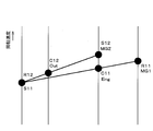
- FIG. 3 shows collinear diagrams of the first differential mechanism 6A and the second differential mechanism 7A.
- “Eng” indicates the internal combustion engine 2
- “MG1” indicates the first motor / generator 3
- “MG2” indicates the second motor / generator 5
- “Out” indicates the output unit 4 (output gear 18). Means each.
- the meanings of the symbols shown in the alignment chart are as described above.
- the sun gear S11 of the first differential mechanism 6A and the ring gear R12 of the second differential mechanism 7A are connected. For this reason, as is apparent from FIG. 3, the rotating elements located at the ends of the collinear charts have the same rotational speed.
- the sun gear S11 and the ring gear R12 are restrained by the case 10 by the brake 29, so that their rotational speeds are zero.
- the sun gear S11 and the ring gear R12 are released and the clutch 30 is turned on, so that they are coupled to the carrier C11 of the first differential mechanism 6A and the sun gear S12 of the second differential mechanism 7A.
- the collinear charts overlap on a straight line. Therefore, there is an advantage that the control is easy because the number of objects to be controlled is limited as compared to the case where the collinear charts do not overlap on a straight line.
- the rotational speed of the ring gear R12 of the second differential mechanism 7A is 0, so that the second motor / generator 5 and the output unit 4 (the output gear 18).
- the ring gear R12 of the second differential mechanism 7A can rotate at the same rotational speed as the sun gear S11 of the first differential mechanism 6A, so that the internal combustion engine 2 and the first motor generator
- the rotational speed ratio between the second motor / generator 5 and the output unit 4 can be changed steplessly.
- the maximum torque required for the second motor / generator 5 can be suppressed by properly using the drive mode in accordance with the speed range, so that the size of the second motor / generator 5 can be suppressed.
- the rotation speed of the second motor / generator 5 is always higher than the rotation speed of the output unit 4. That is, since the rotation of the second motor / generator 5 is decelerated by the second differential mechanism 7A, the driving force of the second motor / generator 5 can be amplified by the second differential mechanism 7A. Therefore, the enlargement of the second motor / generator 5 can be further reduced. Further, in the series hybrid mode, the rotational speeds of the sun gear S11 and the ring gear R12 located at the end of each collinear diagram are 0, so that each of the first motor / generator 3 and the second motor / generator 5 is in the same direction. Rotate.
- the sun gear S11 and the ring gear R12 are connected, in the collinear diagram of the second differential mechanism 7A, the distance between the ring gear R12 and the carrier C12 is not far from that when other elements are connected. That is, since the distance is smaller than 1 when the distance between the sun gear S12 and the carrier C12 is 1, the reduction ratio of the second motor / generator 5 can be made appropriate and the first motor / generator can be made. 3 over-rotation can be suppressed.
- FIG. 4 is a skeleton diagram schematically showing the overall configuration of the driving apparatus according to the second embodiment.
- the drive device 1B includes a first differential mechanism 6B and a second differential mechanism 7B.
- the first differential mechanism 6B is configured as a single pinion type planetary gear mechanism having three rotational elements that can rotate differentially with each other.
- the first differential mechanism 6B rotates a sun gear S21 that is an external gear, a ring gear R21 that is an internal gear disposed coaxially with the sun gear S21, and a pinion P21 that meshes with these gears S21 and R21.
- a carrier C21 that is revolved.
- the internal combustion engine 2 is connected to the carrier C21 via the input shaft 9
- the first motor / generator 3 is connected to the ring gear R21.
- the carrier C21 corresponds to the first rotating element according to the present invention
- the ring gear R21 corresponds to the second rotating element according to the present invention
- the sun gear S21 as the remaining rotating element corresponds to the third rotating element according to the present invention. Equivalent to.
- the second differential mechanism 7B is configured as a single pinion type planetary gear mechanism having three rotating elements that can be differentially rotated with respect to each other.
- the second differential mechanism 7B rotates a sun gear S22 that is an external gear, a ring gear R22 that is an internal gear coaxially disposed with respect to the sun gear S22, and a pinion P22 that meshes with these gears S22 and R22.
- a carrier C22 that is held to revolve freely.
- the output unit 4 is connected to the carrier C22
- the second motor / generator 5 is connected to the ring gear R22.
- the carrier C22 corresponds to the first rotating element according to the present invention
- the ring gear R22 corresponds to the second rotating element according to the present invention
- the sun gear S22 as the remaining rotating element corresponds to the third rotating element according to the present invention. Equivalent to.
- the driving device 1B is provided with a connecting member 34 that connects the sun gear S21 of the first differential mechanism 6B and the sun gear S22 of the second differential mechanism 7B so as to be integrally rotatable.
- the connecting member 34 extends on the axis of the input shaft 9 and penetrates the second motor / generator 5 and the output unit 4.
- a brake 35 is provided as an engaging means at the end 34 a of the connecting member 34. The brake 35 can switch between restraining the connection member 34 to the case 10 and releasing it. That is, the brake 35 can switch between a fixed state in which the sun gear S21 of the first differential mechanism 6B and the sun gear S22 of the second differential mechanism 7B are restrained by the case 10 and a released state in which the restraint is released.
- the brake 35 sandwiches the components of the first motor / generator 3, the first differential mechanism 6 ⁇ / b> B, the second differential mechanism 7 ⁇ / b> B, the second motor / generator 5, and the output unit 4. It is arranged on the opposite side of the internal combustion engine 2. Therefore, the outer diameter of the brake 35 can be reduced as compared with the case where the brake 29 is disposed on the outer periphery of the component as in the first embodiment of the brake 29 shown in FIG. Thereby, it can contribute to size reduction of the radial direction of the drive device 1B.
- the driving device 1B is interposed between the carrier C21 of the first differential mechanism 6B and the ring gear R22 of the second differential mechanism 7B, and connects these elements so as to be integrally rotatable, A clutch 36 that switches between a released state and a released state is provided.
- FIG. 5 shows collinear diagrams of the first differential mechanism 6B and the second differential mechanism 7B.
- the driving device 1B includes (1) a point where the collinear charts overlap each other in the series parallel hybrid mode, and (2) the second motor generator 5 and the output unit 4 in the series parallel hybrid mode. (3) The rotation speed of the second motor / generator 5 is always decelerated by the second differential mechanism 7B in the series hybrid mode, and (4) each time in the series hybrid mode.
- the first mode is that the first motor / generator 3 and the second motor / generator 5 rotate in the same direction when the rotational speeds of the sun gear S21 and the sun gear S22 located at the end of the alignment chart become zero.
- the same effects as the driving apparatus 1A can be obtained as far as these common points are concerned.
- FIG. 6 is a skeleton diagram schematically showing the overall configuration of the driving apparatus according to the third embodiment.
- the drive device 1C includes a first differential mechanism 6C and a second differential mechanism 7C.
- the first differential mechanism 6C is configured as a single pinion type planetary gear mechanism having three rotational elements that are differentially rotatable with respect to each other.
- the first differential mechanism 6 ⁇ / b> C rotates a sun gear S ⁇ b> 31 that is an external gear, a ring gear R ⁇ b> 31 that is an internal gear disposed coaxially with the sun gear S ⁇ b> 31, and a pinion P ⁇ b> 31 that meshes with these gears S ⁇ b> 31 and R ⁇ b> 31.
- a carrier C31 that is held to revolve freely.
- the internal combustion engine 2 is connected to the carrier C31 via the input shaft 9, and the first motor / generator 3 is connected to the sun gear S31.
- the carrier C31 corresponds to the first rotating element according to the present invention
- the sun gear S31 corresponds to the second rotating element according to the present invention
- the ring gear R31 as the remaining rotating element corresponds to the third rotating element according to the present invention. Equivalent to.
- the second differential mechanism 7 ⁇ / b> C is configured as a single pinion type planetary gear mechanism having three rotational elements capable of differential rotation with respect to each other.
- the second differential mechanism 7 ⁇ / b> C rotates a sun gear S ⁇ b> 32 that is an external gear, a ring gear R ⁇ b> 32 that is an internal gear disposed coaxially with the sun gear S ⁇ b> 32, and a pinion P ⁇ b> 32 that meshes with these gears S ⁇ b> 32 and R ⁇ b> 32.
- a carrier C32 that is held to revolve freely.
- the output unit 4 is connected to the ring gear R32
- the second motor / generator 5 is connected to the sun gear S32.
- the ring gear R32 corresponds to the first rotating element according to the present invention
- the sun gear S32 corresponds to the second rotating element according to the present invention
- the carrier C32 as the remaining rotating element corresponds to the third rotating element according to the present invention. Equivalent to.
- the driving device 1C includes a connecting member 44 that connects the ring gear R31 of the first differential mechanism 6C and the carrier C32 of the second differential mechanism 7C so as to be integrally rotatable, and the ring gear of the first differential mechanism 6C.
- the brake 45 capable of switching between a fixed state in which the carrier C32 of the R31 and the second differential mechanism 7C is restrained to the case 10 and a released state in which the restraint is released, the sun gear S31 of the first differential mechanism 6C, and the second differential A clutch 46 is provided between the ring gear R32 of the mechanism 7C and switches between a connected state in which these elements are connected so as to be integrally rotatable and a released state in which the connection is released.
- the drive device 1C operates the brake 45 and the clutch 46 in the state shown in the operation engagement table of FIG. 2, thereby driving between the series hybrid mode and the series parallel hybrid mode. Can be switched.
- FIG. 7 shows collinear diagrams of the first differential mechanism 6C and the second differential mechanism 7C.
- the driving device 1C is (1) a point in which the collinear charts overlap each other in the series parallel hybrid mode, and (2) the second motor generator 5 and the output unit 4 in the series parallel hybrid mode.
- the drive according to the first aspect is that the rotation speed ratio of the second motor / generator 5 can be changed steplessly and (3) the rotation of the second motor / generator 5 is always decelerated by the second differential mechanism 7C in the series hybrid mode. In common with the device 1A, the same effect as that of the driving device 1A can be obtained as far as these common points are concerned.
- FIG. 8 is a skeleton diagram schematically showing the overall configuration of the driving apparatus according to the fourth embodiment.
- the driving device 1D includes a first differential mechanism 6D and a second differential mechanism 7D.
- the first differential mechanism 6D is configured as a double pinion type planetary gear mechanism having three rotational elements that can rotate differentially with each other.
- the first differential mechanism 6D includes a sun gear S41 that is an external gear, a ring gear R41 that is an internal gear disposed coaxially with the sun gear S41, a first pinion P41a that meshes with the sun gear S41, and a ring gear R41. And a carrier C41 that holds the second pinion P41b meshing with each other so as to rotate and revolve in a state of meshing with each other.
- the internal combustion engine 2 is connected to the carrier C41 via the input shaft 9, and the first motor / generator 3 is connected to the sun gear S41.
- the carrier C41 corresponds to the first rotating element according to the present invention
- the sun gear S41 corresponds to the second rotating element according to the present invention
- the ring gear R41 as the remaining rotating element corresponds to the third rotating element according to the present invention. Equivalent to.
- the second differential mechanism 7D is configured as a single pinion type planetary gear mechanism having three rotational elements that can rotate differentially with each other.
- the second differential mechanism 7D rotates a sun gear S42 that is an external gear, a ring gear R42 that is an internal gear coaxially disposed with respect to the sun gear S42, and a pinion P42 that meshes with these gears S42 and R42. And a carrier C42 that is held to revolve freely.
- the output unit 4 is connected to the ring gear R42
- the second motor / generator 5 is connected to the sun gear S42.
- the ring gear R42 corresponds to the first rotating element according to the present invention
- the sun gear S42 corresponds to the second rotating element according to the present invention
- the carrier C42 as the remaining rotating element corresponds to the third rotating element according to the present invention. Equivalent to.
- the driving device 1D is provided with a connecting member 54 that connects the ring gear R41 of the first differential mechanism 6D and the carrier C42 of the second differential mechanism 7D so as to be integrally rotatable.
- An extension member 53 extending on the axis of the input shaft 9 and penetrating through the second motor / generator 5 is coupled to the carrier C42 of the second differential mechanism 7D.
- a brake 55 as an engaging means is provided at the end 53 a of the extension member 53. The brake 55 can switch between restraining the extension member 53 to the case 10 and releasing it.
- the brake 55 can switch between a fixed state in which the ring gear R41 of the first differential mechanism 6D and the carrier C42 of the second differential mechanism 6D are restrained to the case 10 and a released state in which the restraint is released.
- the brake 55 sandwiches the components of the first motor / generator 3, the first differential mechanism 6 ⁇ / b> D, the second differential mechanism 7 ⁇ / b> D, the second motor / generator 5, and the output unit 4. It is arranged on the opposite side of the internal combustion engine 2. Therefore, as in the second embodiment, the outer diameter of the brake 55 can be reduced, which can contribute to the reduction in the radial direction of the drive device 1D.
- the driving device 1D is interposed between the sun gear S41 of the first differential mechanism 6D and the ring gear R42 of the second differential mechanism 7D, and connects these elements so as to be integrally rotatable and releases the connection.
- a clutch 56 that switches between the released state and the released state is provided.
- the drive device 1D operates the brake 55 and the clutch 56 in the state shown in the operation engagement table of FIG. 2 so that the drive mode is switched between the series hybrid mode and the series parallel hybrid mode. Can be switched.
- FIG. 9 shows collinear diagrams of the first differential mechanism 6C and the second differential mechanism 7C.
- the driving device 1D has (1) a point where the collinear charts overlap each other in the series parallel hybrid mode, and (2) the second motor generator 5 and the output unit 4 in the series parallel hybrid mode. And (3) driving according to the first embodiment in that the rotation of the second motor / generator 5 is always decelerated by the second differential mechanism 7D in the series hybrid mode.
- the drive device 1D can easily configure the differential mechanisms 6D and 7D so that the reduction ratios of the internal combustion engine 1 and the second motor / generator 5 at each drive mode and mechanical point are appropriate. High practicality.
- the mechanical point is an operating state in which the rotation speed of the first motor / generator 3 becomes zero when the brake 55 and the clutch 56 are each turned OFF.
- the present invention is not limited to the above embodiments, and can be implemented in various forms within the scope of the gist of the present invention.
- the connection form between the rotating elements of the first differential mechanism and the second differential mechanism and the elements such as the internal combustion engine and the output unit, and the connection form between the first differential mechanism and the second differential mechanism are shown in the above embodiments. There are many variations in these connection forms.
- the rotating elements located at the end of each collinear diagram are connected to each other, so that the two collinear diagrams are V-shaped. Join. Therefore, this connection form is referred to as a V-coupled type.
- the third embodiment as shown in FIG.
- FIG. 10A shows an alignment chart according to a first modified example of the V coupling type.
- the ring gear R1 of the first differential mechanism and the ring gear R2 of the second differential mechanism are connected, and a brake as an engaging means is provided on these rotating elements, and the first differential mechanism A clutch is provided between the carrier C1 and the sun gear S2 of the second differential mechanism.
- the alignment chart of the second differential mechanism of the output system is shorter than the alignment chart of the first differential mechanism.
- the first differential mechanism includes a carrier C1 as a first rotating element, a sun gear S1 as a second rotating element, and a ring gear R1 as a third rotating element, and a second differential.
- the mechanism includes a carrier C2 as a first rotating element, a sun gear S2 as a second rotating element, and a ring gear R2 as a third rotating element.
- FIG. 10B shows a collinear diagram according to a second modification of the V coupling type.
- the ring gear R1 of the first differential mechanism and the ring gear R2 of the second differential mechanism are connected, and a brake as an engagement means is provided on these rotating elements, and the first differential mechanism is provided.
- a clutch is provided between the sun gear S1 and the carrier C2 of the second differential mechanism.
- the alignment chart of the second differential mechanism of the output system is longer than the alignment chart of the first differential mechanism.
- the first differential mechanism includes a carrier C1 as a first rotating element, a sun gear S1 as a second rotating element, and a ring gear R1 as a third rotating element, and a second differential.
- the mechanism includes a carrier C2 as a first rotating element, a sun gear S2 as a second rotating element, and a ring gear R2 as a third rotating element.
- FIG. 10C shows an alignment chart according to a third modification of the V coupling type.
- the sun gear S1 of the first differential mechanism and the ring gear R2 of the second differential mechanism are connected, and a brake as an engaging means is provided on these rotating elements, and the first differential mechanism A clutch is provided between the ring gear R1 and the carrier C2 of the second differential mechanism.
- the alignment chart of the second differential mechanism of the output system is longer than the alignment chart of the first differential mechanism.
- the first differential mechanism includes a carrier C1 as a first rotation element, a ring gear R1 as a second rotation element, and a sun gear S1 as a third rotation element, and a second differential.
- the mechanism includes a carrier C2 as a first rotating element, a sun gear S2 as a second rotating element, and a ring gear R2 as a third rotating element.
- FIG. 10D shows a collinear diagram according to a fourth modification of the V coupling type.
- the ring gear R1 of the first differential mechanism and the sun gear S2 of the second differential mechanism are connected, and a brake as an engaging means is provided on these rotating elements, and the first differential mechanism A clutch is provided between the carrier C1 and the ring gear R2 of the second differential mechanism.
- the alignment chart of the second differential mechanism of the output system is shorter than the alignment chart of the first differential mechanism.
- the first differential mechanism includes a carrier C1 as a first rotating element, a sun gear S1 as a second rotating element, and a ring gear R1 as a third rotating element, and a second differential.
- the mechanism includes a carrier C2 as a first rotating element, a ring gear R2 as a second rotating element, and a sun gear S2 as a third rotating element.
- FIG. 10E shows an alignment chart according to a fifth modification of the V coupling type.
- the ring gear R1 of the first differential mechanism and the sun gear S2 of the second differential mechanism are connected, and a brake as an engagement means is provided on these rotating elements, and the first differential mechanism A clutch is provided between the sun gear S1 and the carrier C2 of the second differential mechanism.
- the alignment chart of the second differential mechanism of the output system is longer than the alignment chart of the first differential mechanism.
- the first differential mechanism includes a carrier C1 as a first rotating element, a sun gear S1 as a second rotating element, and a ring gear R1 as a third rotating element, and a second differential.
- the mechanism includes a carrier C2 as a first rotating element, a ring gear R2 as a second rotating element, and a sun gear S2 as a third rotating element.
- FIG. 10F shows an alignment chart according to a sixth modification of the V-coupling type.
- the sun gear S1 of the first differential mechanism and the sun gear S2 of the second differential mechanism are connected, and a brake as an engaging means is provided on these rotating elements, and the ring of the first differential mechanism is provided.
- a clutch is provided between the gear R1 and the carrier C2 of the second differential mechanism.
- the alignment chart of the second differential mechanism of the output system is longer than the alignment chart of the first differential mechanism.
- the first differential mechanism includes a carrier C1 as a first rotating element, a ring gear R1 as a second rotating element, and a sun gear S1 as a third rotating element, and the second differential mechanism.
- the mechanism includes a carrier C2 as a first rotating element, a ring gear R2 as a second rotating element, and a sun gear S2 as a third rotating element.
- Each of the V-coupled modification examples shown in FIGS. 10A to 10F includes (1) a point where the collinear diagrams overlap each other in the series parallel hybrid mode, and (2) a second motor generator 5 in the series parallel hybrid mode. (3) The speed of the second motor / generator 5 is always decelerated by the second differential mechanism in the series hybrid mode, and (4) With respect to the point that each of the first motor / generator 3 and the second motor / generator 5 rotates in the same direction when the rotation speed of the rotating element located at the end of each collinear diagram becomes 0 in the series hybrid mode. It is common to the first and second forms that are combined, and as far as their common points are concerned, the same effects as the first and second forms can be obtained. That.
- FIG. 11A to FIG. 11G show collinear diagrams according to modifications of the T coupling type.
- FIG. 11A shows an alignment chart according to a first modification of the T coupling type.
- the carrier C1 of the first differential mechanism and the ring gear R2 of the second differential mechanism are connected, and a brake as an engaging means is provided on these rotating elements, and the first differential mechanism A clutch is provided between the sun gear S1 and the sun gear S2 of the second differential mechanism.
- the alignment chart of the second differential mechanism of the output system is shorter than the alignment chart of the first differential mechanism.
- the first differential mechanism includes a sun gear S1 as a first rotation element, a ring gear R1 as a second rotation element, and a carrier C1 as a third rotation element, and the second differential mechanism.
- the mechanism includes a carrier C2 as a first rotating element, a sun gear S2 as a second rotating element, and a ring gear R2 as a third rotating element.
- FIG. 11B shows a collinear diagram according to a second modification of the T coupling type.
- the carrier C1 of the first differential mechanism and the ring gear R2 of the second differential mechanism are coupled, and a brake as an engaging means is provided on these rotating elements, and the first differential mechanism A clutch is provided between the ring gear R1 and the sun gear S2 of the second differential mechanism.
- the alignment chart of the second differential mechanism of the output system is shorter than the alignment chart of the first differential mechanism.
- the first differential mechanism includes a ring gear R1 as a first rotation element, a sun gear S1 as a second rotation element, and a carrier C1 as a third rotation element, and a second differential.
- the mechanism includes a carrier C2 as a first rotating element, a sun gear S2 as a second rotating element, and a ring gear R2 as a third rotating element.
- FIG. 11C shows a collinear diagram according to a third modification of the T coupling type.
- the ring gear R1 of the first differential mechanism and the carrier C2 of the second differential mechanism are connected, and a brake as an engaging means is provided on these rotating elements, and the first differential mechanism A clutch is provided between the sun gear S1 and the sun gear S2 of the second differential mechanism.
- the alignment chart of the second differential mechanism of the output system is longer than the alignment chart of the first differential mechanism.
- the first differential mechanism includes a carrier C1 as a first rotating element, a sun gear S1 as a second rotating element, and a ring gear R1 as a third rotating element, and a second differential.
- the mechanism includes a sun gear S2 as a first rotating element, a ring gear R2 as a second rotating element, and a carrier C2 as a third rotating element.
- FIG. 11D shows an alignment chart according to a fourth modification of the T coupling type.
- the carrier C1 of the first differential mechanism and the sun gear S2 of the second differential mechanism are connected, and a brake as an engaging means is provided on these rotating elements, and the sun gear of the first differential mechanism is provided.
- a clutch is provided between S1 and the ring gear R2 of the second differential mechanism.
- the alignment chart of the second differential mechanism of the output system is shorter than the alignment chart of the first differential mechanism.
- the first differential mechanism includes a sun gear S1 as a first rotating element, a ring gear R1 as a second rotating element, and a carrier C1 as a third rotating element, and a second differential.
- the mechanism includes a carrier C2 as a first rotating element, a ring gear R2 as a second rotating element, and a sun gear S2 as a third rotating element.
- FIG. 11E shows an alignment chart according to a fifth modification of the T coupling type.
- the carrier C1 of the first differential mechanism and the sun gear S2 of the second differential mechanism are connected, and a brake as an engagement means is provided on these rotating elements, and the ring of the first differential mechanism is provided.
- a clutch is provided between the gear R1 and the ring gear R2 of the second differential mechanism.
- the alignment chart of the second differential mechanism of the output system is shorter than the alignment chart of the first differential mechanism.
- the first differential mechanism includes a ring gear R1 as a first rotation element, a sun gear S1 as a second rotation element, and a carrier C1 as a third rotation element, and a second differential mechanism.
- the mechanism includes a carrier C2 as a first rotating element, a ring gear R2 as a second rotating element, and a sun gear S2 as a third rotating element.
- FIG. 11F shows an alignment chart according to a sixth modified example of the T coupling type.
- the sun gear S1 of the first differential mechanism and the carrier C2 of the second differential mechanism are connected, and a brake as an engaging means is provided on these rotating elements, and the ring of the first differential mechanism is provided.
- a clutch is provided between the gear R1 and the sun gear S2 of the second differential mechanism.
- the alignment chart of the second differential mechanism of the output system is longer than the alignment chart of the first differential mechanism.
- the first differential mechanism includes a carrier C1 as a first rotating element, a ring gear R1 as a second rotating element, and a sun gear S1 as a third rotating element, and the second differential mechanism.
- the mechanism includes a sun gear S2 as a first rotating element, a ring gear R2 as a second rotating element, and a carrier C2 as a third rotating element.
- FIG. 11G shows an alignment chart according to a seventh modified example of the T coupling type.
- the sun gear S1 of the first differential mechanism and the carrier C2 of the second differential mechanism are connected, and a brake as an engaging means is provided on these rotating elements, and the ring of the first differential mechanism is provided.
- a clutch is provided between the gear R1 and the ring gear R2 of the second differential mechanism.
- the alignment chart of the second differential mechanism of the output system is longer than the alignment chart of the first differential mechanism.
- the first differential mechanism includes a carrier C1 as a first rotating element, a ring gear R1 as a second rotating element, and a sun gear S1 as a third rotating element, and a second differential.
- the mechanism has a ring gear R2 as a first rotating element, a sun gear S2 as a second rotating element, and a carrier C2 as a third rotating element.
- Each of the T-coupled modifications shown in FIGS. 11A to 11G includes (1) a point where the collinear charts overlap each other in the series parallel hybrid mode, and (2) a second motor generator in the series parallel hybrid mode. 5 and the third embodiment that is T-coupled in that the rotation speed ratio between the output unit 4 and the output unit 4 can be changed steplessly. As far as these common points are concerned, the same effect as the third embodiment can be obtained. .
- FIG. 12A shows an alignment chart according to a first modified example of the X coupling type.
- the carrier C1 of the first differential mechanism and the carrier C2 of the second differential mechanism are connected, and a brake as an engaging means is provided on these rotating elements, and the sun gear of the first differential mechanism is provided.
- a clutch is provided between S1 and the sun gear S2 of the second differential mechanism.
- the alignment chart of the second differential mechanism of the output system is shorter than the alignment chart of the first differential mechanism.
- the first differential mechanism includes a ring gear R1 as a first rotating element, a sun gear S1 as a second rotating element, and a carrier C1 as a third rotating element, and a second differential.
- the mechanism includes a sun gear S2 as a first rotating element, a ring gear R2 as a second rotating element, and a carrier C2 as a third rotating element.
- FIG. 12B shows an alignment chart according to a second modified example of the X coupling type.
- the carrier C1 of the first differential mechanism and the carrier C2 of the second differential mechanism are coupled, and a brake as an engaging means is provided on these rotating elements, and the ring of the first differential mechanism is provided.
- a clutch is provided between the gear R1 and the ring gear R2 of the second differential mechanism.
- the alignment chart of the second differential mechanism of the output system is shorter than the alignment chart of the first differential mechanism.
- the first differential mechanism includes a ring gear R1 as a first rotation element, a sun gear S1 as a second rotation element, and a carrier C1 as a third rotation element, and a second differential.
- the mechanism includes a sun gear S2 as a first rotating element, a ring gear R2 as a second rotating element, and a carrier C2 as a third rotating element.
- FIG. 12C shows an alignment chart according to a third modified example of the X coupling type.
- the carrier C1 of the first differential mechanism and the carrier C2 of the second differential mechanism are coupled, and a brake as an engaging means is provided on these rotating elements, and the sun gear of the first differential mechanism is provided.
- a clutch is provided between S1 and the ring gear R2 of the second differential mechanism.
- the alignment chart of the second differential mechanism of the output system is longer than the alignment chart of the first differential mechanism.
- the first differential mechanism includes a sun gear S1 as a first rotation element, a ring gear R1 as a second rotation element, and a carrier C1 as a third rotation element, and a second differential.
- the mechanism includes a sun gear S2 as a first rotating element, a ring gear R2 as a second rotating element, and a carrier C2 as a third rotating element.
- FIG. 12D shows an alignment chart according to a fourth modified example of the X coupling type.
- the carrier C1 of the first differential mechanism and the carrier C2 of the second differential mechanism are coupled, and a brake as an engaging means is provided on these rotating elements, and the ring of the first differential mechanism is provided.
- a clutch is provided between the gear R1 and the ring gear R2 of the second differential mechanism.
- the alignment chart of the second differential mechanism of the output system is longer than the alignment chart of the first differential mechanism.
- the first differential mechanism includes a ring gear R1 as a first rotating element, a sun gear S1 as a second rotating element, and a carrier C1 as a third rotating element, and a second differential.
- the mechanism includes a sun gear S2 as a first rotating element, a ring gear R2 as a second rotating element, and a carrier C2 as a third rotating element.
- FIG. 12E shows an alignment chart according to a fifth modified example of the X coupling type.
- the carrier C1 of the first differential mechanism and the carrier C2 of the second differential mechanism are connected, and a brake as an engaging means is provided on these rotating elements, and the ring of the first differential mechanism is provided.
- a clutch is provided between the gear R1 and the ring gear R2 of the second differential mechanism.
- the alignment chart of the second differential mechanism of the output system is shorter than the alignment chart of the first differential mechanism.
- the first differential mechanism includes a sun gear S1 as the first rotation element, a ring gear R1 as the second rotation element, and a carrier C1 as the third rotation element, and the second differential mechanism.
- the mechanism has a ring gear R2 as a first rotating element, a sun gear S2 as a second rotating element, and a carrier C2 as a third rotating element.
- FIG. 12F shows an alignment chart according to a sixth modified example of the X coupling type.
- the carrier C1 of the first differential mechanism and the carrier C2 of the second differential mechanism are connected, and a brake as an engaging means is provided on these rotating elements, and the ring of the first differential mechanism is provided.
- a clutch is provided between the gear R1 and the sun gear S2 of the second differential mechanism.
- the alignment chart of the second differential mechanism of the output system is shorter than the alignment chart of the first differential mechanism.
- the first differential mechanism includes a ring gear R1 as the first rotation element, a sun gear S1 as the second rotation element, and a carrier C1 as the third rotation element, and the second differential mechanism.
- the mechanism has a ring gear R2 as a first rotating element, a sun gear S2 as a second rotating element, and a carrier C2 as a third rotating element.
- FIG. 12G shows an alignment chart according to a seventh modified example of the X coupling type.
- the carrier C1 of the first differential mechanism and the carrier C2 of the second differential mechanism are connected, and a brake as an engaging means is provided on these rotating elements, and the sun gear of the first differential mechanism is provided.
- a clutch is provided between S1 and the ring gear R2 of the second differential mechanism.
- the alignment chart of the second differential mechanism of the output system is longer than the alignment chart of the first differential mechanism.
- the first differential mechanism includes a ring gear R1 as a first rotation element, a sun gear S1 as a second rotation element, and a carrier C1 as a third rotation element, and the second differential mechanism.
- the mechanism has a ring gear R2 as a first rotating element, a sun gear S2 as a second rotating element, and a carrier C2 as a third rotating element.
- Each of the X-coupled modifications shown in FIGS. 12A to 12G includes (1) a point where the collinear diagrams overlap each other in the series parallel hybrid mode, and (2) a second motor generator in the series parallel hybrid mode.
- the fourth embodiment that is an X-coupled type in that the rotation speed ratio between the output unit 4 and the output unit 4 can be changed steplessly, the same effect as the fourth embodiment can be obtained as far as these common points are concerned. .
- the configuration of the first differential mechanism and the second differential mechanism with a planetary gear mechanism is merely an example.
- a friction wheel (roller) in which at least one of the first differential mechanism and the second differential mechanism is not a gear is used.
- the present invention can also be implemented by replacing the first motor / generator 3 with a generator.
- the present invention can be implemented by replacing the second motor / generator 5 with an electric motor.
Landscapes
- Engineering & Computer Science (AREA)
- Chemical & Material Sciences (AREA)
- Combustion & Propulsion (AREA)
- Transportation (AREA)
- Mechanical Engineering (AREA)
- Hybrid Electric Vehicles (AREA)
- Arrangement Of Transmissions (AREA)
Abstract
Priority Applications (5)
| Application Number | Priority Date | Filing Date | Title |
|---|---|---|---|
| DE112010005487T DE112010005487T5 (de) | 2010-04-14 | 2010-04-14 | Fahrzeugantriebseinheit |
| JP2010541643A JP5177235B2 (ja) | 2010-04-14 | 2010-04-14 | 車両の駆動装置 |
| CN2010800019116A CN102292232A (zh) | 2010-04-14 | 2010-04-14 | 车辆的驱动装置 |
| US13/000,662 US20110256974A1 (en) | 2010-04-14 | 2010-04-14 | Vehicular drive unit technical field |
| PCT/JP2010/056707 WO2011128998A1 (fr) | 2010-04-14 | 2010-04-14 | Dispositif d'entraînement de véhicule |
Applications Claiming Priority (1)
| Application Number | Priority Date | Filing Date | Title |
|---|---|---|---|
| PCT/JP2010/056707 WO2011128998A1 (fr) | 2010-04-14 | 2010-04-14 | Dispositif d'entraînement de véhicule |
Publications (1)
| Publication Number | Publication Date |
|---|---|
| WO2011128998A1 true WO2011128998A1 (fr) | 2011-10-20 |
Family
ID=44788607
Family Applications (1)
| Application Number | Title | Priority Date | Filing Date |
|---|---|---|---|
| PCT/JP2010/056707 WO2011128998A1 (fr) | 2010-04-14 | 2010-04-14 | Dispositif d'entraînement de véhicule |
Country Status (5)
| Country | Link |
|---|---|
| US (1) | US20110256974A1 (fr) |
| JP (1) | JP5177235B2 (fr) |
| CN (1) | CN102292232A (fr) |
| DE (1) | DE112010005487T5 (fr) |
| WO (1) | WO2011128998A1 (fr) |
Cited By (5)
| Publication number | Priority date | Publication date | Assignee | Title |
|---|---|---|---|---|
| WO2013140543A1 (fr) * | 2012-03-21 | 2013-09-26 | トヨタ自動車株式会社 | Dispositif de commande d'entraînement pour véhicule hybride |
| JP2016150676A (ja) * | 2015-02-18 | 2016-08-22 | トヨタ自動車株式会社 | ハイブリッド車両 |
| JP2016150677A (ja) * | 2015-02-18 | 2016-08-22 | トヨタ自動車株式会社 | ハイブリッド車両 |
| US9440526B2 (en) | 2013-05-13 | 2016-09-13 | Toyota Jidosha Kabushiki Kaisha | Drive system for hybrid vehicle |
| JPWO2014184852A1 (ja) * | 2013-05-13 | 2017-02-23 | トヨタ自動車株式会社 | ハイブリッド車両用駆動装置 |
Families Citing this family (21)
| Publication number | Priority date | Publication date | Assignee | Title |
|---|---|---|---|---|
| JP4229156B2 (ja) * | 2006-09-06 | 2009-02-25 | トヨタ自動車株式会社 | 動力出力装置およびハイブリッド自動車 |
| EP2567844B1 (fr) * | 2010-05-07 | 2016-03-23 | Honda Motor Co., Ltd. | Système de propulsion de véhicule hybride |
| WO2012073651A1 (fr) * | 2010-12-03 | 2012-06-07 | 本田技研工業株式会社 | Dispositif d'entraînement hybride |
| US8585521B2 (en) * | 2011-03-16 | 2013-11-19 | GM Global Technology Operations LLC | Variable ratio power-split hybrid transmission |
| JP5954408B2 (ja) * | 2012-03-21 | 2016-07-20 | トヨタ自動車株式会社 | ハイブリッド車両の駆動制御装置 |
| KR101795377B1 (ko) * | 2012-04-19 | 2017-11-10 | 현대자동차 주식회사 | 하이브리드 차량 변속기 및 시동 제어 방법 |
| KR101416420B1 (ko) * | 2013-06-24 | 2014-07-09 | 현대자동차 주식회사 | 하이브리드 차량용 변속장치 |
| KR101484219B1 (ko) * | 2013-06-24 | 2015-01-19 | 현대자동차 주식회사 | 하이브리드 차량용 변속장치 |
| US10421350B2 (en) * | 2015-10-20 | 2019-09-24 | Oshkosh Corporation | Inline electromechanical variable transmission system |
| CN105128645A (zh) * | 2015-08-18 | 2015-12-09 | 张楠 | 一种混合动力总成、车辆及控制系统 |
| CN106476607B (zh) * | 2015-08-31 | 2019-06-07 | 比亚迪股份有限公司 | 动力传动系统及具有其的车辆 |
| CN106476599B (zh) * | 2015-08-31 | 2019-03-29 | 比亚迪股份有限公司 | 动力传动系统及具有其的车辆 |
| CN106476609B (zh) * | 2015-08-31 | 2019-03-29 | 比亚迪股份有限公司 | 动力传动系统及具有其的车辆 |
| CN106627094B (zh) * | 2015-10-28 | 2019-05-31 | 长城汽车股份有限公司 | 混合动力系统 |
| JP2017105365A (ja) * | 2015-12-10 | 2017-06-15 | トヨタ自動車株式会社 | ハイブリッド車両の駆動力制御装置 |
| JP6353576B1 (ja) * | 2017-03-22 | 2018-07-04 | 株式会社ユニバンス | 動力伝達装置 |
| CN109203963B (zh) * | 2017-06-29 | 2023-12-22 | 广州汽车集团股份有限公司 | 汽车混合动力耦合系统及其控制方法 |
| US11306802B2 (en) * | 2018-04-02 | 2022-04-19 | Dana Limited | Traction device |
| US11299027B2 (en) * | 2018-07-09 | 2022-04-12 | Ningbo Umd Automatic Transmission Co., Ltd. | Power system for hybrid vehicles |
| EP3848215B1 (fr) * | 2018-09-04 | 2023-07-19 | Ningbo Umd Automatic Transmission Co., Ltd. | Transmission pour un véhicule hybride |
| CN111055670B (zh) * | 2019-12-20 | 2022-01-18 | 浙江吉利汽车研究院有限公司 | 一种多档位汽车混合动力驱动装置及汽车 |
Citations (6)
| Publication number | Priority date | Publication date | Assignee | Title |
|---|---|---|---|---|
| JPS5030223A (fr) * | 1973-07-20 | 1975-03-26 | ||
| JPH07336810A (ja) * | 1994-06-06 | 1995-12-22 | Aqueous Res:Kk | ハイブリッド型車両 |
| JP2001055052A (ja) * | 1999-08-18 | 2001-02-27 | Nissan Motor Co Ltd | 車両の駆動装置 |
| JP2003237392A (ja) * | 2002-12-03 | 2003-08-27 | Toyota Motor Corp | 動力出力装置およびハイブリッド車両並びにその制御方法 |
| JP2005029027A (ja) * | 2003-07-04 | 2005-02-03 | Toyota Motor Corp | ハイブリッド車の駆動装置 |
| JP2009126233A (ja) * | 2007-11-20 | 2009-06-11 | Aisin Seiki Co Ltd | ハイブリッド車両 |
Family Cites Families (4)
| Publication number | Priority date | Publication date | Assignee | Title |
|---|---|---|---|---|
| JP4038183B2 (ja) * | 2004-01-19 | 2008-01-23 | トヨタ自動車株式会社 | 動力出力装置およびこれを搭載する自動車並びに動力伝達装置 |
| JP4203828B2 (ja) * | 2006-07-10 | 2009-01-07 | アイシン・エィ・ダブリュ株式会社 | ハイブリッド駆動装置 |
| US7507174B2 (en) * | 2006-07-14 | 2009-03-24 | Gm Global Technology Operations, Inc. | Electrically variable transmission having three planetary gear sets |
| US7479080B2 (en) * | 2006-07-24 | 2009-01-20 | Gm Global Technology Operations, Inc. | Hybrid architecture incorporating three motor generators and brakes |
-
2010
- 2010-04-14 DE DE112010005487T patent/DE112010005487T5/de not_active Withdrawn
- 2010-04-14 JP JP2010541643A patent/JP5177235B2/ja not_active Expired - Fee Related
- 2010-04-14 CN CN2010800019116A patent/CN102292232A/zh active Pending
- 2010-04-14 US US13/000,662 patent/US20110256974A1/en not_active Abandoned
- 2010-04-14 WO PCT/JP2010/056707 patent/WO2011128998A1/fr active Application Filing
Patent Citations (6)
| Publication number | Priority date | Publication date | Assignee | Title |
|---|---|---|---|---|
| JPS5030223A (fr) * | 1973-07-20 | 1975-03-26 | ||
| JPH07336810A (ja) * | 1994-06-06 | 1995-12-22 | Aqueous Res:Kk | ハイブリッド型車両 |
| JP2001055052A (ja) * | 1999-08-18 | 2001-02-27 | Nissan Motor Co Ltd | 車両の駆動装置 |
| JP2003237392A (ja) * | 2002-12-03 | 2003-08-27 | Toyota Motor Corp | 動力出力装置およびハイブリッド車両並びにその制御方法 |
| JP2005029027A (ja) * | 2003-07-04 | 2005-02-03 | Toyota Motor Corp | ハイブリッド車の駆動装置 |
| JP2009126233A (ja) * | 2007-11-20 | 2009-06-11 | Aisin Seiki Co Ltd | ハイブリッド車両 |
Cited By (6)
| Publication number | Priority date | Publication date | Assignee | Title |
|---|---|---|---|---|
| WO2013140543A1 (fr) * | 2012-03-21 | 2013-09-26 | トヨタ自動車株式会社 | Dispositif de commande d'entraînement pour véhicule hybride |
| US9440526B2 (en) | 2013-05-13 | 2016-09-13 | Toyota Jidosha Kabushiki Kaisha | Drive system for hybrid vehicle |
| JPWO2014184854A1 (ja) * | 2013-05-13 | 2017-02-23 | トヨタ自動車株式会社 | ハイブリッド車両の駆動装置 |
| JPWO2014184852A1 (ja) * | 2013-05-13 | 2017-02-23 | トヨタ自動車株式会社 | ハイブリッド車両用駆動装置 |
| JP2016150676A (ja) * | 2015-02-18 | 2016-08-22 | トヨタ自動車株式会社 | ハイブリッド車両 |
| JP2016150677A (ja) * | 2015-02-18 | 2016-08-22 | トヨタ自動車株式会社 | ハイブリッド車両 |
Also Published As
| Publication number | Publication date |
|---|---|
| CN102292232A (zh) | 2011-12-21 |
| DE112010005487T5 (de) | 2013-03-21 |
| JPWO2011128998A1 (ja) | 2013-07-11 |
| JP5177235B2 (ja) | 2013-04-03 |
| US20110256974A1 (en) | 2011-10-20 |
Similar Documents
| Publication | Publication Date | Title |
|---|---|---|
| JP5177235B2 (ja) | 車両の駆動装置 | |
| JP6451524B2 (ja) | ハイブリッド車両用駆動装置 | |
| JP4100444B1 (ja) | ハイブリッド駆動装置 | |
| US8439782B2 (en) | Automatic transmission | |
| JP5141802B2 (ja) | ハイブリッド駆動装置 | |
| WO2014184852A1 (fr) | Systeme d'entrainement de vehicule hybride | |
| WO2012169410A1 (fr) | Dispositif d'entraînement pour véhicule | |
| JP2009067212A (ja) | ハイブリッド駆動装置 | |
| KR101558691B1 (ko) | 하이브리드 파워트레인 및 그 hev-hv 구동력모드 전환 방법 | |
| JP2008114812A (ja) | ハイブリッド駆動装置 | |
| JP4333618B2 (ja) | ハイブリッド駆動装置 | |
| JP5994934B2 (ja) | ハイブリッド車両用駆動装置 | |
| CN103470702A (zh) | 具有偏置电动机和两个行星齿轮组的双模式电可变变速器 | |
| JP2009248825A (ja) | ハイブリッド駆動装置 | |
| JP2012126154A (ja) | ハイブリッド駆動装置 | |
| JP4919080B2 (ja) | 動力出力装置 | |
| JP4458017B2 (ja) | ハイブリッド駆動装置 | |
| JP2010269717A (ja) | 車両の駆動装置 | |
| JP2004011674A (ja) | 車両用自動変速機 | |
| JP5062122B2 (ja) | 車両の駆動装置 | |
| WO2018181557A1 (fr) | Dispositif d'entraînement pour véhicule | |
| JP2018154207A (ja) | ハイブリッド駆動装置 | |
| WO2018079843A1 (fr) | Appareil de boîte de vitesses d'entraînement de véhicule | |
| JP4930267B2 (ja) | ハイブリッド車の駆動装置 | |
| WO2018079842A1 (fr) | Dispositif d'entraînement pour véhicule |
Legal Events
| Date | Code | Title | Description |
|---|---|---|---|
| WWE | Wipo information: entry into national phase |
Ref document number: 201080001911.6 Country of ref document: CN |
|
| WWE | Wipo information: entry into national phase |
Ref document number: 2010541643 Country of ref document: JP |
|
| WWE | Wipo information: entry into national phase |
Ref document number: 13000662 Country of ref document: US |
|
| 121 | Ep: the epo has been informed by wipo that ep was designated in this application |
Ref document number: 10849835 Country of ref document: EP Kind code of ref document: A1 |
|
| WWE | Wipo information: entry into national phase |
Ref document number: 1120100054878 Country of ref document: DE Ref document number: 112010005487 Country of ref document: DE |
|
| 122 | Ep: pct application non-entry in european phase |
Ref document number: 10849835 Country of ref document: EP Kind code of ref document: A1 |