WO2011125767A1 - ハニカムフィルタ - Google Patents
ハニカムフィルタ Download PDFInfo
- Publication number
- WO2011125767A1 WO2011125767A1 PCT/JP2011/058077 JP2011058077W WO2011125767A1 WO 2011125767 A1 WO2011125767 A1 WO 2011125767A1 JP 2011058077 W JP2011058077 W JP 2011058077W WO 2011125767 A1 WO2011125767 A1 WO 2011125767A1
- Authority
- WO
- WIPO (PCT)
- Prior art keywords
- cell
- cells
- honeycomb filter
- collection layer
- layer
- Prior art date
Links
- 239000007787 solid Substances 0.000 claims abstract description 36
- 239000012530 fluid Substances 0.000 claims abstract description 20
- 238000005192 partition Methods 0.000 claims description 86
- 239000002245 particle Substances 0.000 claims description 73
- 239000010419 fine particle Substances 0.000 claims description 34
- 239000011148 porous material Substances 0.000 claims description 26
- VYPSYNLAJGMNEJ-UHFFFAOYSA-N Silicium dioxide Chemical compound O=[Si]=O VYPSYNLAJGMNEJ-UHFFFAOYSA-N 0.000 claims description 25
- 239000003054 catalyst Substances 0.000 claims description 22
- 239000000779 smoke Substances 0.000 claims description 22
- 238000012360 testing method Methods 0.000 claims description 22
- HBMJWWWQQXIZIP-UHFFFAOYSA-N silicon carbide Chemical compound [Si+]#[C-] HBMJWWWQQXIZIP-UHFFFAOYSA-N 0.000 claims description 17
- 229910010271 silicon carbide Inorganic materials 0.000 claims description 17
- 229910003465 moissanite Inorganic materials 0.000 claims description 16
- MCMNRKCIXSYSNV-UHFFFAOYSA-N Zirconium dioxide Chemical compound O=[Zr]=O MCMNRKCIXSYSNV-UHFFFAOYSA-N 0.000 claims description 14
- GWEVSGVZZGPLCZ-UHFFFAOYSA-N Titan oxide Chemical compound O=[Ti]=O GWEVSGVZZGPLCZ-UHFFFAOYSA-N 0.000 claims description 12
- PNEYBMLMFCGWSK-UHFFFAOYSA-N aluminium oxide Inorganic materials [O-2].[O-2].[O-2].[Al+3].[Al+3] PNEYBMLMFCGWSK-UHFFFAOYSA-N 0.000 claims description 11
- 229910010272 inorganic material Inorganic materials 0.000 claims description 11
- 239000011147 inorganic material Substances 0.000 claims description 11
- 239000002994 raw material Substances 0.000 claims description 11
- 239000000377 silicon dioxide Substances 0.000 claims description 11
- 229910052878 cordierite Inorganic materials 0.000 claims description 9
- JSKIRARMQDRGJZ-UHFFFAOYSA-N dimagnesium dioxido-bis[(1-oxido-3-oxo-2,4,6,8,9-pentaoxa-1,3-disila-5,7-dialuminabicyclo[3.3.1]nonan-7-yl)oxy]silane Chemical compound [Mg++].[Mg++].[O-][Si]([O-])(O[Al]1O[Al]2O[Si](=O)O[Si]([O-])(O1)O2)O[Al]1O[Al]2O[Si](=O)O[Si]([O-])(O1)O2 JSKIRARMQDRGJZ-UHFFFAOYSA-N 0.000 claims description 9
- -1 sialon Chemical compound 0.000 claims description 8
- 229910000505 Al2TiO5 Inorganic materials 0.000 claims description 7
- KZHJGOXRZJKJNY-UHFFFAOYSA-N dioxosilane;oxo(oxoalumanyloxy)alumane Chemical compound O=[Si]=O.O=[Si]=O.O=[Al]O[Al]=O.O=[Al]O[Al]=O.O=[Al]O[Al]=O KZHJGOXRZJKJNY-UHFFFAOYSA-N 0.000 claims description 7
- 229910052863 mullite Inorganic materials 0.000 claims description 7
- AABBHSMFGKYLKE-SNAWJCMRSA-N propan-2-yl (e)-but-2-enoate Chemical compound C\C=C\C(=O)OC(C)C AABBHSMFGKYLKE-SNAWJCMRSA-N 0.000 claims description 7
- 229910052581 Si3N4 Inorganic materials 0.000 claims description 6
- HQVNEWCFYHHQES-UHFFFAOYSA-N silicon nitride Chemical compound N12[Si]34N5[Si]62N3[Si]51N64 HQVNEWCFYHHQES-UHFFFAOYSA-N 0.000 claims description 6
- 229910000166 zirconium phosphate Inorganic materials 0.000 claims description 6
- LEHFSLREWWMLPU-UHFFFAOYSA-B zirconium(4+);tetraphosphate Chemical compound [Zr+4].[Zr+4].[Zr+4].[O-]P([O-])([O-])=O.[O-]P([O-])([O-])=O.[O-]P([O-])([O-])=O.[O-]P([O-])([O-])=O LEHFSLREWWMLPU-UHFFFAOYSA-B 0.000 claims description 6
- 238000005304 joining Methods 0.000 claims description 3
- 238000007689 inspection Methods 0.000 claims description 2
- 238000002485 combustion reaction Methods 0.000 abstract description 9
- 239000000470 constituent Substances 0.000 abstract 6
- 238000011084 recovery Methods 0.000 abstract 2
- 239000010410 layer Substances 0.000 description 177
- 241000264877 Hippospongia communis Species 0.000 description 144
- 239000013618 particulate matter Substances 0.000 description 51
- 230000008929 regeneration Effects 0.000 description 35
- 238000011069 regeneration method Methods 0.000 description 35
- 239000007789 gas Substances 0.000 description 34
- 230000000052 comparative effect Effects 0.000 description 27
- 238000000034 method Methods 0.000 description 22
- 238000004519 manufacturing process Methods 0.000 description 18
- 230000002093 peripheral effect Effects 0.000 description 14
- 239000010954 inorganic particle Substances 0.000 description 13
- 239000000463 material Substances 0.000 description 13
- 230000008569 process Effects 0.000 description 12
- 238000007789 sealing Methods 0.000 description 11
- 230000008021 deposition Effects 0.000 description 9
- 239000012784 inorganic fiber Substances 0.000 description 8
- XLYOFNOQVPJJNP-UHFFFAOYSA-N water Substances O XLYOFNOQVPJJNP-UHFFFAOYSA-N 0.000 description 8
- 238000010586 diagram Methods 0.000 description 7
- 238000010438 heat treatment Methods 0.000 description 7
- BASFCYQUMIYNBI-UHFFFAOYSA-N platinum Chemical compound [Pt] BASFCYQUMIYNBI-UHFFFAOYSA-N 0.000 description 7
- 239000002585 base Substances 0.000 description 6
- 230000015572 biosynthetic process Effects 0.000 description 6
- 239000002002 slurry Substances 0.000 description 6
- KDLHZDBZIXYQEI-UHFFFAOYSA-N Palladium Chemical compound [Pd] KDLHZDBZIXYQEI-UHFFFAOYSA-N 0.000 description 5
- 239000011230 binding agent Substances 0.000 description 5
- 238000009826 distribution Methods 0.000 description 5
- 238000009434 installation Methods 0.000 description 5
- 238000005259 measurement Methods 0.000 description 5
- 239000011347 resin Substances 0.000 description 5
- 229920005989 resin Polymers 0.000 description 5
- VTYYLEPIZMXCLO-UHFFFAOYSA-L Calcium carbonate Chemical compound [Ca+2].[O-]C([O-])=O VTYYLEPIZMXCLO-UHFFFAOYSA-L 0.000 description 4
- 230000008859 change Effects 0.000 description 4
- 229910052723 transition metal Inorganic materials 0.000 description 4
- 239000004215 Carbon black (E152) Substances 0.000 description 3
- 229920000742 Cotton Polymers 0.000 description 3
- 239000008119 colloidal silica Substances 0.000 description 3
- 238000002591 computed tomography Methods 0.000 description 3
- 239000002612 dispersion medium Substances 0.000 description 3
- 230000000694 effects Effects 0.000 description 3
- 229930195733 hydrocarbon Natural products 0.000 description 3
- 150000002430 hydrocarbons Chemical class 0.000 description 3
- 230000001678 irradiating effect Effects 0.000 description 3
- 230000007246 mechanism Effects 0.000 description 3
- QSHDDOUJBYECFT-UHFFFAOYSA-N mercury Chemical compound [Hg] QSHDDOUJBYECFT-UHFFFAOYSA-N 0.000 description 3
- 229910052753 mercury Inorganic materials 0.000 description 3
- 229910000510 noble metal Inorganic materials 0.000 description 3
- 230000035699 permeability Effects 0.000 description 3
- 229910052697 platinum Inorganic materials 0.000 description 3
- 239000002904 solvent Substances 0.000 description 3
- 239000002344 surface layer Substances 0.000 description 3
- 150000003624 transition metals Chemical class 0.000 description 3
- 238000011144 upstream manufacturing Methods 0.000 description 3
- 238000012800 visualization Methods 0.000 description 3
- 229910052784 alkaline earth metal Inorganic materials 0.000 description 2
- 150000001342 alkaline earth metals Chemical class 0.000 description 2
- 229910052788 barium Inorganic materials 0.000 description 2
- 229910052791 calcium Inorganic materials 0.000 description 2
- 239000011575 calcium Substances 0.000 description 2
- 229910000019 calcium carbonate Inorganic materials 0.000 description 2
- 239000013025 ceria-based material Substances 0.000 description 2
- 239000004927 clay Substances 0.000 description 2
- 238000010276 construction Methods 0.000 description 2
- 230000007423 decrease Effects 0.000 description 2
- 238000001514 detection method Methods 0.000 description 2
- HNPSIPDUKPIQMN-UHFFFAOYSA-N dioxosilane;oxo(oxoalumanyloxy)alumane Chemical compound O=[Si]=O.O=[Al]O[Al]=O HNPSIPDUKPIQMN-UHFFFAOYSA-N 0.000 description 2
- 239000000835 fiber Substances 0.000 description 2
- 239000000446 fuel Substances 0.000 description 2
- 239000010931 gold Substances 0.000 description 2
- 230000000873 masking effect Effects 0.000 description 2
- 239000002609 medium Substances 0.000 description 2
- 229910052751 metal Inorganic materials 0.000 description 2
- 239000002184 metal Substances 0.000 description 2
- 229920000609 methyl cellulose Polymers 0.000 description 2
- 239000001923 methylcellulose Substances 0.000 description 2
- 235000010981 methylcellulose Nutrition 0.000 description 2
- 229910052763 palladium Inorganic materials 0.000 description 2
- 238000005498 polishing Methods 0.000 description 2
- 238000002360 preparation method Methods 0.000 description 2
- 238000012545 processing Methods 0.000 description 2
- 238000000746 purification Methods 0.000 description 2
- 229910052761 rare earth metal Inorganic materials 0.000 description 2
- 150000002910 rare earth metals Chemical class 0.000 description 2
- 239000010948 rhodium Substances 0.000 description 2
- 239000004065 semiconductor Substances 0.000 description 2
- 238000005507 spraying Methods 0.000 description 2
- 229910052712 strontium Inorganic materials 0.000 description 2
- 238000009834 vaporization Methods 0.000 description 2
- 230000008016 vaporization Effects 0.000 description 2
- 229910052684 Cerium Inorganic materials 0.000 description 1
- 229910052688 Gadolinium Inorganic materials 0.000 description 1
- 229910052779 Neodymium Inorganic materials 0.000 description 1
- BPQQTUXANYXVAA-UHFFFAOYSA-N Orthosilicate Chemical compound [O-][Si]([O-])([O-])[O-] BPQQTUXANYXVAA-UHFFFAOYSA-N 0.000 description 1
- 239000004372 Polyvinyl alcohol Substances 0.000 description 1
- 229910052777 Praseodymium Inorganic materials 0.000 description 1
- 229910052772 Samarium Inorganic materials 0.000 description 1
- BQCADISMDOOEFD-UHFFFAOYSA-N Silver Chemical compound [Ag] BQCADISMDOOEFD-UHFFFAOYSA-N 0.000 description 1
- 229910021536 Zeolite Inorganic materials 0.000 description 1
- 239000003463 adsorbent Substances 0.000 description 1
- 229910052783 alkali metal Inorganic materials 0.000 description 1
- 150000001340 alkali metals Chemical class 0.000 description 1
- 229910000323 aluminium silicate Inorganic materials 0.000 description 1
- 238000009529 body temperature measurement Methods 0.000 description 1
- 229910052792 caesium Inorganic materials 0.000 description 1
- 238000004364 calculation method Methods 0.000 description 1
- 239000000919 ceramic Substances 0.000 description 1
- CETPSERCERDGAM-UHFFFAOYSA-N ceric oxide Chemical compound O=[Ce]=O CETPSERCERDGAM-UHFFFAOYSA-N 0.000 description 1
- GWXLDORMOJMVQZ-UHFFFAOYSA-N cerium Chemical compound [Ce] GWXLDORMOJMVQZ-UHFFFAOYSA-N 0.000 description 1
- 229910000422 cerium(IV) oxide Inorganic materials 0.000 description 1
- 229910052804 chromium Inorganic materials 0.000 description 1
- 239000011248 coating agent Substances 0.000 description 1
- 238000000576 coating method Methods 0.000 description 1
- 229910052802 copper Inorganic materials 0.000 description 1
- 238000005520 cutting process Methods 0.000 description 1
- 230000003247 decreasing effect Effects 0.000 description 1
- 239000006185 dispersion Substances 0.000 description 1
- 238000001035 drying Methods 0.000 description 1
- 239000000428 dust Substances 0.000 description 1
- 238000001914 filtration Methods 0.000 description 1
- 239000003205 fragrance Substances 0.000 description 1
- 239000003574 free electron Substances 0.000 description 1
- PCHJSUWPFVWCPO-UHFFFAOYSA-N gold Chemical compound [Au] PCHJSUWPFVWCPO-UHFFFAOYSA-N 0.000 description 1
- 229910052737 gold Inorganic materials 0.000 description 1
- 238000010191 image analysis Methods 0.000 description 1
- 229910052742 iron Inorganic materials 0.000 description 1
- 238000004898 kneading Methods 0.000 description 1
- 229910052746 lanthanum Inorganic materials 0.000 description 1
- 239000004973 liquid crystal related substance Substances 0.000 description 1
- 229910052744 lithium Inorganic materials 0.000 description 1
- 238000011068 loading method Methods 0.000 description 1
- 229910052749 magnesium Inorganic materials 0.000 description 1
- 229910052748 manganese Inorganic materials 0.000 description 1
- 238000002156 mixing Methods 0.000 description 1
- 239000000203 mixture Substances 0.000 description 1
- 229910052759 nickel Inorganic materials 0.000 description 1
- 230000003287 optical effect Effects 0.000 description 1
- 230000003647 oxidation Effects 0.000 description 1
- 238000007254 oxidation reaction Methods 0.000 description 1
- 230000001590 oxidative effect Effects 0.000 description 1
- 239000012466 permeate Substances 0.000 description 1
- 229920003023 plastic Polymers 0.000 description 1
- 239000004033 plastic Substances 0.000 description 1
- 229920002451 polyvinyl alcohol Polymers 0.000 description 1
- 238000002459 porosimetry Methods 0.000 description 1
- 229910052700 potassium Inorganic materials 0.000 description 1
- 239000000843 powder Substances 0.000 description 1
- 238000003825 pressing Methods 0.000 description 1
- 230000000644 propagated effect Effects 0.000 description 1
- 230000009467 reduction Effects 0.000 description 1
- 229910052703 rhodium Inorganic materials 0.000 description 1
- MHOVAHRLVXNVSD-UHFFFAOYSA-N rhodium atom Chemical compound [Rh] MHOVAHRLVXNVSD-UHFFFAOYSA-N 0.000 description 1
- 229910052706 scandium Inorganic materials 0.000 description 1
- 239000003566 sealing material Substances 0.000 description 1
- VSZWPYCFIRKVQL-UHFFFAOYSA-N selanylidenegallium;selenium Chemical compound [Se].[Se]=[Ga].[Se]=[Ga] VSZWPYCFIRKVQL-UHFFFAOYSA-N 0.000 description 1
- 239000011863 silicon-based powder Substances 0.000 description 1
- XJKVPKYVPCWHFO-UHFFFAOYSA-N silicon;hydrate Chemical compound O.[Si] XJKVPKYVPCWHFO-UHFFFAOYSA-N 0.000 description 1
- 229910052709 silver Inorganic materials 0.000 description 1
- 239000004332 silver Substances 0.000 description 1
- 238000005245 sintering Methods 0.000 description 1
- 229910052708 sodium Inorganic materials 0.000 description 1
- 239000007858 starting material Substances 0.000 description 1
- 238000003860 storage Methods 0.000 description 1
- 239000000758 substrate Substances 0.000 description 1
- 230000001629 suppression Effects 0.000 description 1
- 239000004094 surface-active agent Substances 0.000 description 1
- 239000013076 target substance Substances 0.000 description 1
- 230000008646 thermal stress Effects 0.000 description 1
- 229910052719 titanium Inorganic materials 0.000 description 1
- 229910052720 vanadium Inorganic materials 0.000 description 1
- 230000000007 visual effect Effects 0.000 description 1
- 239000002912 waste gas Substances 0.000 description 1
- 229910052727 yttrium Inorganic materials 0.000 description 1
- 239000010457 zeolite Substances 0.000 description 1
- 229910052725 zinc Inorganic materials 0.000 description 1
Images


Classifications
-
- B—PERFORMING OPERATIONS; TRANSPORTING
- B01—PHYSICAL OR CHEMICAL PROCESSES OR APPARATUS IN GENERAL
- B01D—SEPARATION
- B01D53/00—Separation of gases or vapours; Recovering vapours of volatile solvents from gases; Chemical or biological purification of waste gases, e.g. engine exhaust gases, smoke, fumes, flue gases, aerosols
- B01D53/34—Chemical or biological purification of waste gases
- B01D53/92—Chemical or biological purification of waste gases of engine exhaust gases
- B01D53/94—Chemical or biological purification of waste gases of engine exhaust gases by catalytic processes
- B01D53/9445—Simultaneously removing carbon monoxide, hydrocarbons or nitrogen oxides making use of three-way catalysts [TWC] or four-way-catalysts [FWC]
-
- B—PERFORMING OPERATIONS; TRANSPORTING
- B01—PHYSICAL OR CHEMICAL PROCESSES OR APPARATUS IN GENERAL
- B01D—SEPARATION
- B01D46/00—Filters or filtering processes specially modified for separating dispersed particles from gases or vapours
- B01D46/24—Particle separators, e.g. dust precipitators, using rigid hollow filter bodies
- B01D46/2403—Particle separators, e.g. dust precipitators, using rigid hollow filter bodies characterised by the physical shape or structure of the filtering element
- B01D46/2418—Honeycomb filters
-
- B—PERFORMING OPERATIONS; TRANSPORTING
- B01—PHYSICAL OR CHEMICAL PROCESSES OR APPARATUS IN GENERAL
- B01J—CHEMICAL OR PHYSICAL PROCESSES, e.g. CATALYSIS OR COLLOID CHEMISTRY; THEIR RELEVANT APPARATUS
- B01J23/00—Catalysts comprising metals or metal oxides or hydroxides, not provided for in group B01J21/00
- B01J23/16—Catalysts comprising metals or metal oxides or hydroxides, not provided for in group B01J21/00 of arsenic, antimony, bismuth, vanadium, niobium, tantalum, polonium, chromium, molybdenum, tungsten, manganese, technetium or rhenium
- B01J23/32—Manganese, technetium or rhenium
- B01J23/34—Manganese
-
- B—PERFORMING OPERATIONS; TRANSPORTING
- B01—PHYSICAL OR CHEMICAL PROCESSES OR APPARATUS IN GENERAL
- B01J—CHEMICAL OR PHYSICAL PROCESSES, e.g. CATALYSIS OR COLLOID CHEMISTRY; THEIR RELEVANT APPARATUS
- B01J23/00—Catalysts comprising metals or metal oxides or hydroxides, not provided for in group B01J21/00
- B01J23/38—Catalysts comprising metals or metal oxides or hydroxides, not provided for in group B01J21/00 of noble metals
- B01J23/54—Catalysts comprising metals or metal oxides or hydroxides, not provided for in group B01J21/00 of noble metals combined with metals, oxides or hydroxides provided for in groups B01J23/02 - B01J23/36
- B01J23/56—Platinum group metals
- B01J23/63—Platinum group metals with rare earths or actinides
-
- B01J35/56—
-
- B—PERFORMING OPERATIONS; TRANSPORTING
- B01—PHYSICAL OR CHEMICAL PROCESSES OR APPARATUS IN GENERAL
- B01J—CHEMICAL OR PHYSICAL PROCESSES, e.g. CATALYSIS OR COLLOID CHEMISTRY; THEIR RELEVANT APPARATUS
- B01J37/00—Processes, in general, for preparing catalysts; Processes, in general, for activation of catalysts
- B01J37/02—Impregnation, coating or precipitation
- B01J37/03—Precipitation; Co-precipitation
- B01J37/038—Precipitation; Co-precipitation to form slurries or suspensions, e.g. a washcoat
-
- C—CHEMISTRY; METALLURGY
- C04—CEMENTS; CONCRETE; ARTIFICIAL STONE; CERAMICS; REFRACTORIES
- C04B—LIME, MAGNESIA; SLAG; CEMENTS; COMPOSITIONS THEREOF, e.g. MORTARS, CONCRETE OR LIKE BUILDING MATERIALS; ARTIFICIAL STONE; CERAMICS; REFRACTORIES; TREATMENT OF NATURAL STONE
- C04B38/00—Porous mortars, concrete, artificial stone or ceramic ware; Preparation thereof
- C04B38/0006—Honeycomb structures
- C04B38/0009—Honeycomb structures characterised by features relating to the cell walls, e.g. wall thickness or distribution of pores in the walls
-
- C—CHEMISTRY; METALLURGY
- C04—CEMENTS; CONCRETE; ARTIFICIAL STONE; CERAMICS; REFRACTORIES
- C04B—LIME, MAGNESIA; SLAG; CEMENTS; COMPOSITIONS THEREOF, e.g. MORTARS, CONCRETE OR LIKE BUILDING MATERIALS; ARTIFICIAL STONE; CERAMICS; REFRACTORIES; TREATMENT OF NATURAL STONE
- C04B38/00—Porous mortars, concrete, artificial stone or ceramic ware; Preparation thereof
- C04B38/0006—Honeycomb structures
- C04B38/0016—Honeycomb structures assembled from subunits
-
- F—MECHANICAL ENGINEERING; LIGHTING; HEATING; WEAPONS; BLASTING
- F01—MACHINES OR ENGINES IN GENERAL; ENGINE PLANTS IN GENERAL; STEAM ENGINES
- F01N—GAS-FLOW SILENCERS OR EXHAUST APPARATUS FOR MACHINES OR ENGINES IN GENERAL; GAS-FLOW SILENCERS OR EXHAUST APPARATUS FOR INTERNAL COMBUSTION ENGINES
- F01N3/00—Exhaust or silencing apparatus having means for purifying, rendering innocuous, or otherwise treating exhaust
- F01N3/02—Exhaust or silencing apparatus having means for purifying, rendering innocuous, or otherwise treating exhaust for cooling, or for removing solid constituents of, exhaust
- F01N3/021—Exhaust or silencing apparatus having means for purifying, rendering innocuous, or otherwise treating exhaust for cooling, or for removing solid constituents of, exhaust by means of filters
- F01N3/022—Exhaust or silencing apparatus having means for purifying, rendering innocuous, or otherwise treating exhaust for cooling, or for removing solid constituents of, exhaust by means of filters characterised by specially adapted filtering structure, e.g. honeycomb, mesh or fibrous
- F01N3/0222—Exhaust or silencing apparatus having means for purifying, rendering innocuous, or otherwise treating exhaust for cooling, or for removing solid constituents of, exhaust by means of filters characterised by specially adapted filtering structure, e.g. honeycomb, mesh or fibrous the structure being monolithic, e.g. honeycombs
-
- B—PERFORMING OPERATIONS; TRANSPORTING
- B01—PHYSICAL OR CHEMICAL PROCESSES OR APPARATUS IN GENERAL
- B01D—SEPARATION
- B01D2255/00—Catalysts
- B01D2255/10—Noble metals or compounds thereof
- B01D2255/102—Platinum group metals
- B01D2255/1021—Platinum
-
- B—PERFORMING OPERATIONS; TRANSPORTING
- B01—PHYSICAL OR CHEMICAL PROCESSES OR APPARATUS IN GENERAL
- B01D—SEPARATION
- B01D2255/00—Catalysts
- B01D2255/10—Noble metals or compounds thereof
- B01D2255/102—Platinum group metals
- B01D2255/1023—Palladium
-
- B—PERFORMING OPERATIONS; TRANSPORTING
- B01—PHYSICAL OR CHEMICAL PROCESSES OR APPARATUS IN GENERAL
- B01D—SEPARATION
- B01D2255/00—Catalysts
- B01D2255/10—Noble metals or compounds thereof
- B01D2255/104—Silver
-
- B—PERFORMING OPERATIONS; TRANSPORTING
- B01—PHYSICAL OR CHEMICAL PROCESSES OR APPARATUS IN GENERAL
- B01D—SEPARATION
- B01D2255/00—Catalysts
- B01D2255/10—Noble metals or compounds thereof
- B01D2255/106—Gold
-
- B—PERFORMING OPERATIONS; TRANSPORTING
- B01—PHYSICAL OR CHEMICAL PROCESSES OR APPARATUS IN GENERAL
- B01D—SEPARATION
- B01D2255/00—Catalysts
- B01D2255/20—Metals or compounds thereof
- B01D2255/206—Rare earth metals
-
- B—PERFORMING OPERATIONS; TRANSPORTING
- B01—PHYSICAL OR CHEMICAL PROCESSES OR APPARATUS IN GENERAL
- B01D—SEPARATION
- B01D2255/00—Catalysts
- B01D2255/20—Metals or compounds thereof
- B01D2255/207—Transition metals
-
- B—PERFORMING OPERATIONS; TRANSPORTING
- B01—PHYSICAL OR CHEMICAL PROCESSES OR APPARATUS IN GENERAL
- B01D—SEPARATION
- B01D2255/00—Catalysts
- B01D2255/90—Physical characteristics of catalysts
- B01D2255/91—NOx-storage component incorporated in the catalyst
-
- B—PERFORMING OPERATIONS; TRANSPORTING
- B01—PHYSICAL OR CHEMICAL PROCESSES OR APPARATUS IN GENERAL
- B01D—SEPARATION
- B01D2255/00—Catalysts
- B01D2255/90—Physical characteristics of catalysts
- B01D2255/912—HC-storage component incorporated in the catalyst
-
- B—PERFORMING OPERATIONS; TRANSPORTING
- B01—PHYSICAL OR CHEMICAL PROCESSES OR APPARATUS IN GENERAL
- B01D—SEPARATION
- B01D2255/00—Catalysts
- B01D2255/90—Physical characteristics of catalysts
- B01D2255/92—Dimensions
- B01D2255/9202—Linear dimensions
-
- B—PERFORMING OPERATIONS; TRANSPORTING
- B01—PHYSICAL OR CHEMICAL PROCESSES OR APPARATUS IN GENERAL
- B01D—SEPARATION
- B01D2255/00—Catalysts
- B01D2255/90—Physical characteristics of catalysts
- B01D2255/92—Dimensions
- B01D2255/9205—Porosity
-
- B—PERFORMING OPERATIONS; TRANSPORTING
- B01—PHYSICAL OR CHEMICAL PROCESSES OR APPARATUS IN GENERAL
- B01J—CHEMICAL OR PHYSICAL PROCESSES, e.g. CATALYSIS OR COLLOID CHEMISTRY; THEIR RELEVANT APPARATUS
- B01J23/00—Catalysts comprising metals or metal oxides or hydroxides, not provided for in group B01J21/00
-
- C—CHEMISTRY; METALLURGY
- C04—CEMENTS; CONCRETE; ARTIFICIAL STONE; CERAMICS; REFRACTORIES
- C04B—LIME, MAGNESIA; SLAG; CEMENTS; COMPOSITIONS THEREOF, e.g. MORTARS, CONCRETE OR LIKE BUILDING MATERIALS; ARTIFICIAL STONE; CERAMICS; REFRACTORIES; TREATMENT OF NATURAL STONE
- C04B2111/00—Mortars, concrete or artificial stone or mixtures to prepare them, characterised by specific function, property or use
- C04B2111/00474—Uses not provided for elsewhere in C04B2111/00
- C04B2111/00793—Uses not provided for elsewhere in C04B2111/00 as filters or diaphragms
-
- F—MECHANICAL ENGINEERING; LIGHTING; HEATING; WEAPONS; BLASTING
- F01—MACHINES OR ENGINES IN GENERAL; ENGINE PLANTS IN GENERAL; STEAM ENGINES
- F01N—GAS-FLOW SILENCERS OR EXHAUST APPARATUS FOR MACHINES OR ENGINES IN GENERAL; GAS-FLOW SILENCERS OR EXHAUST APPARATUS FOR INTERNAL COMBUSTION ENGINES
- F01N2330/00—Structure of catalyst support or particle filter
- F01N2330/06—Ceramic, e.g. monoliths
-
- F—MECHANICAL ENGINEERING; LIGHTING; HEATING; WEAPONS; BLASTING
- F01—MACHINES OR ENGINES IN GENERAL; ENGINE PLANTS IN GENERAL; STEAM ENGINES
- F01N—GAS-FLOW SILENCERS OR EXHAUST APPARATUS FOR MACHINES OR ENGINES IN GENERAL; GAS-FLOW SILENCERS OR EXHAUST APPARATUS FOR INTERNAL COMBUSTION ENGINES
- F01N2330/00—Structure of catalyst support or particle filter
- F01N2330/60—Discontinuous, uneven properties of filter material, e.g. different material thickness along the longitudinal direction; Higher filter capacity upstream than downstream in same housing
-
- F—MECHANICAL ENGINEERING; LIGHTING; HEATING; WEAPONS; BLASTING
- F01—MACHINES OR ENGINES IN GENERAL; ENGINE PLANTS IN GENERAL; STEAM ENGINES
- F01N—GAS-FLOW SILENCERS OR EXHAUST APPARATUS FOR MACHINES OR ENGINES IN GENERAL; GAS-FLOW SILENCERS OR EXHAUST APPARATUS FOR INTERNAL COMBUSTION ENGINES
- F01N2510/00—Surface coverings
- F01N2510/06—Surface coverings for exhaust purification, e.g. catalytic reaction
- F01N2510/068—Surface coverings for exhaust purification, e.g. catalytic reaction characterised by the distribution of the catalytic coatings
- F01N2510/0682—Surface coverings for exhaust purification, e.g. catalytic reaction characterised by the distribution of the catalytic coatings having a discontinuous, uneven or partially overlapping coating of catalytic material, e.g. higher amount of material upstream than downstream or vice versa
-
- F—MECHANICAL ENGINEERING; LIGHTING; HEATING; WEAPONS; BLASTING
- F01—MACHINES OR ENGINES IN GENERAL; ENGINE PLANTS IN GENERAL; STEAM ENGINES
- F01N—GAS-FLOW SILENCERS OR EXHAUST APPARATUS FOR MACHINES OR ENGINES IN GENERAL; GAS-FLOW SILENCERS OR EXHAUST APPARATUS FOR INTERNAL COMBUSTION ENGINES
- F01N3/00—Exhaust or silencing apparatus having means for purifying, rendering innocuous, or otherwise treating exhaust
- F01N3/02—Exhaust or silencing apparatus having means for purifying, rendering innocuous, or otherwise treating exhaust for cooling, or for removing solid constituents of, exhaust
- F01N3/021—Exhaust or silencing apparatus having means for purifying, rendering innocuous, or otherwise treating exhaust for cooling, or for removing solid constituents of, exhaust by means of filters
- F01N3/033—Exhaust or silencing apparatus having means for purifying, rendering innocuous, or otherwise treating exhaust for cooling, or for removing solid constituents of, exhaust by means of filters in combination with other devices
- F01N3/035—Exhaust or silencing apparatus having means for purifying, rendering innocuous, or otherwise treating exhaust for cooling, or for removing solid constituents of, exhaust by means of filters in combination with other devices with catalytic reactors, e.g. catalysed diesel particulate filters
-
- Y—GENERAL TAGGING OF NEW TECHNOLOGICAL DEVELOPMENTS; GENERAL TAGGING OF CROSS-SECTIONAL TECHNOLOGIES SPANNING OVER SEVERAL SECTIONS OF THE IPC; TECHNICAL SUBJECTS COVERED BY FORMER USPC CROSS-REFERENCE ART COLLECTIONS [XRACs] AND DIGESTS
- Y02—TECHNOLOGIES OR APPLICATIONS FOR MITIGATION OR ADAPTATION AGAINST CLIMATE CHANGE
- Y02T—CLIMATE CHANGE MITIGATION TECHNOLOGIES RELATED TO TRANSPORTATION
- Y02T10/00—Road transport of goods or passengers
- Y02T10/10—Internal combustion engine [ICE] based vehicles
- Y02T10/12—Improving ICE efficiencies
Definitions
- the present invention relates to a honeycomb filter.
- a honeycomb filter a cell in which one end is opened and the other end is plugged, and a cell in which one end is plugged and the other end is opened alternately
- a porous partition wall formed to be disposed and a layer for collecting and removing particulate matter (PM) contained in the exhaust gas formed on the partition wall are formed.
- PM particulate matter
- a “regeneration process” for recovering the function of the filter by burning the collected PM may be performed.
- the pressure loss can be reduced by providing a collection layer on the partition wall, but there is no significant difference in the efficiency of the regeneration process only by providing the collection layer.
- the regeneration process for example, a process of increasing the temperature of the engine by increasing the fuel of the engine is performed, so that it has been required to more efficiently remove the collected solid component from the viewpoint of fuel consumption.
- the present invention has been made in view of such problems, and a main object thereof is to provide a honeycomb filter that can more efficiently remove the collected solid components.
- the present invention adopts the following means in order to achieve the main object described above.
- the honeycomb filter of the present invention is A plurality of porous partition walls that are open at one end and plugged at the other end to form a plurality of cells serving as fluid flow paths; And a collection layer that is a layer that is formed on the partition wall and collects and removes a solid component contained in the fluid.
- fine particles having an average particle diameter determined based on the average pore diameter of the partition walls are gauged from one end face side of the honeycomb filter.
- a pressure test is performed in which the pressure is supplied under a pressure of 1 Pa or more and 10 Pa or less, and the other end face is irradiated with light to visualize the fine particles flowing out from the end face. In the visualization test, the luminance difference is 150 cd / m 2 or more. Is present in the cell, and the ratio R (%) of the number of overdeposited cells to the total number of cells is 0 (%) ⁇ R ⁇ 20 (%).
- the honeycomb filter of the present invention is A plurality of porous partition walls that are open at one end and plugged at the other end to form a plurality of cells serving as fluid flow paths; And a collection layer that is a layer that is formed on the partition wall and collects and removes a solid component contained in the fluid. After the solid component is collected, there is an overdeposition cell including an overdeposition region in which more of the solid component is collected, and the ratio R of the overdeposition cell number to the total cell number R (%) May be 0 (%) ⁇ R ⁇ 20 (%).
- a trapping layer is formed on the partition walls forming the cells.
- this cell there are overdeposited cells that exhibit a predetermined luminance difference in the visualization test.
- This overdeposition cell is formed so that the ratio R (%) of the overdeposition cell to the total number of cells is 0 (%) ⁇ R ⁇ 20 (%).
- the regeneration speed tends to increase according to the amount of the collected solid component.
- a large amount of solid components are accumulated in the overdeposition cell, and the regeneration of the solid component in the overdeposition cell can serve as an ignition point and more efficiently remove the collected solid component. it can.
- this honeycomb filter there is at least one overdeposited cell, and the ratio R of the number of overdeposited cells to the total number of cells is 20 (%) or less.
- the ratio R is 20 (%) or less, the pressure loss can be effectively reduced, and the collected solid component can be more efficiently removed.
- This “over-deposition cell” may be a cell that collects more solid components than other general cells after collecting the solid components, or any of the adjacent cells. Alternatively, a cell in which 10% by weight or more of solid components are deposited with respect to one or more may be used.
- the term “crack” refers to a cell in which at least an inlet side into which fluid flows is opened (also referred to as an inlet side cell) and a cell in which at least an outlet side from which fluid flows out (also referred to as an outlet side cell).
- the partition wall in between it exists in the carrier axial direction that penetrates the inlet side cell and outlet side cell, or its vertical cross-sectional direction, and refers to a rift of a size that affects the PM collection performance .
- the collection layer may be formed in the inlet side cell, and the overdeposition cell may exist in the inlet side cell of the fluid.
- the overdeposition cell may be a cell that collects more solid components than other cells after the solid components are collected.
- the ratio R of the overdeposited cells to the total number of cells is 7 (%) or less. If it carries out like this, the collected solid component can be removed more efficiently, reducing pressure loss more.
- the overdeposition cell may be at least one of a cell in which the collection layer is incompletely formed and a cell in which the collection layer is not formed. In this way, the flow resistance of the over-deposition cell is lower than that of the cell in which the collection layer is completely formed, so that more fluid flows in comparison with other cells, and as a result, Many solid components can be collected. That is, an overdeposition cell can be produced relatively easily by making the collection layer incomplete.
- the “cell in which the collection layer is incompletely formed” may be, for example, a cell in which a collection layer relatively thinner than the thickness of the collection layer in other parts is formed. .
- the relatively thin collection layer may have a thickness of 30% or less, more preferably 50% or less with respect to the average thickness of the collection layer in the entire honeycomb filter.
- a cell in which the collection layer is incompletely formed means that a collection layer having the same thickness as other parts is formed, but the collection layer is formed in at least a part of the cell. It is good also as what has an unformed local unformed part.
- the local non-formed site may be located in any location with respect to the fluid flow direction, and the maximum length of the local non-formed site may be 300 ⁇ m or less, more preferably 200 ⁇ m or less.
- the collection layer may be formed with an area of 75% or less with respect to the entire inner wall area of one cell, or the collection layer is formed with an area of 50% or less.
- the trapping layer may be formed with an area of 25% or less.
- the overdeposition cell is preferably one in which the collection layer is not formed. In this way, the flow path resistance can be further reduced, and more solid components can be easily collected.
- the collection layer may be formed by supplying an inorganic material, which is a raw material of the collection layer, to the cell using gas as a carrier medium. If it carries out like this, the formation state of a collection layer, such as the thickness of a collection layer, can be controlled comparatively easily using conveyance by gas.
- the over-deposition cell is detected by pressurizing and supplying fine particles from one end face side of the honeycomb filter, and irradiating light on the other end face to visualize the fine particles flowing out from the end face. It may be possible. By doing so, it is possible to detect the overdeposition cell by a relatively easy method of emitting light emitted from the end face. In this detection method, for example, fine particles with a clear particle size distribution and concentration are introduced from one end face of the honeycomb filter in a dark room, laser light is irradiated to the other end face in a slit shape, and fine particles leaking from the other end face are used. The generated luminance difference may be detected.
- examples of the “fine particles” supplied from the end face include fine particles due to burning of incense such as incense, fine particles due to spraying and vaporization of a solvent such as water, and fine particles due to generation of fine particles such as calcium carbonate.
- the fine particles are fine particles having an average particle diameter determined based on the average pore diameter of the partition wall, that is, fine particles selected according to the permeability to the partition wall. It is good also as a particle
- the pressure supply condition is that the gauge pressure is 1 Pa or more and 10 Pa or less.
- the overdeposition cell is a cell having a luminance difference of 150 cd / m 2 or more from the lowest luminance among the cells.
- the partition wall includes one or more inorganic materials selected from cordierite, SiC, mullite, aluminum titanate, alumina, silicon nitride, sialon, zirconium phosphate, zirconia, titania and silica. It is good also as what is formed by.
- the collection layer is formed to include one or more inorganic materials selected from cordierite, SiC, mullite, aluminum titanate, alumina, silicon nitride, sialon, zirconium phosphate, zirconia, titania and silica. It is good as it is. At this time, it is preferable that the collection layer is formed of the same kind of material as the partition wall.
- the honeycomb filter of the present invention may be formed by joining two or more honeycomb segments having the partition walls and the collection layer with a joining layer. If it carries out like this, the mechanical strength of a honey-comb filter can be raised more by joining by a joining layer.
- a catalyst may be supported on at least one of the partition wall and the collection layer. In this way, purification of components contained in the fluid, such as combustion removal of the collected solid components, can be performed more efficiently.
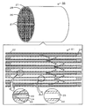
- FIG. 3 is an explanatory diagram illustrating an example of a schematic configuration of a honeycomb filter 20.
- FIG. It is explanatory drawing of the calculation method of the thickness of the collection layer by SEM observation.
- 3 is a conceptual diagram of PM collection in an overdeposition cell 25.
- FIG. It is explanatory drawing of the temperature change at the time of the regeneration process by the overdeposition cell 25.
- FIG. 3 is an explanatory diagram illustrating an example of a schematic configuration of a honeycomb filter 40.
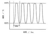
- FIG. It is explanatory drawing of the heat cycle at the time of a regeneration process. It is a figure showing the relationship between the regeneration efficiency with respect to the ratio of an overdeposition cell, and a pressure-loss increase rate.
- FIG. 1 is an explanatory diagram showing an example of a schematic configuration of a honeycomb filter 20 according to an embodiment of the present invention.
- FIG. 2 is an explanatory view of a method for calculating the thickness of the collection layer by SEM observation
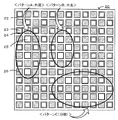
- FIG. 3 is an explanatory view of the overdeposition cells 25 formed in a distributed manner in the outer peripheral portion, the central portion.
- 4 is an explanatory diagram of the laser smoke detector 60
- FIG. 5 is a conceptual diagram of PM collection in the overdeposition cell 25
- FIG. 6 is a temperature change during regeneration processing by the overdeposition cell 25. It is explanatory drawing of. As shown in FIG.
- the honeycomb filter 20 of the present embodiment has a shape in which two or more honeycomb segments 21 having partition walls 22 are joined by a joining layer 27, and an outer peripheral protection part 28 is formed on the outer periphery thereof. ing.
- the honeycomb filter 20 has a porous partition wall in which one end portion is opened and the other end portion is plugged by a plugging portion 26 to form a plurality of cells 23 serving as exhaust gas flow paths as fluid.
- a collection layer 24 that is a layer that is formed on the partition wall 22 and collects and removes a solid component (hereinafter also referred to as PM) contained in the fluid.
- PM solid component
- the partition wall 22 includes a cell 23 in which one end is opened and the other end is plugged, and a cell in which one end is plugged and the other end is opened. 23 are alternately arranged.
- the exhaust gas that has entered the cell 23 also referred to as an inlet-side cell
- the cell 23 (the outlet-side cell) has an opening on the outlet side. The PM contained in the exhaust gas is collected on the collection layer 24 at this time.
- the outer shape of the honeycomb filter 20 is not particularly limited, but may be a columnar shape, a quadrangular columnar shape, an elliptical columnar shape, a hexagonal columnar shape, or the like.
- the outer shape of the honeycomb segment 21 is not particularly limited, but preferably has a flat surface that can be easily joined, and can have a polygonal prismatic shape (such as a quadrangular prism shape or a hexagonal prism shape).
- the cell may have a cross-sectional shape of a polygon such as a triangle, a quadrangle, a hexagon, and an octagon, a streamline shape such as a circle and an ellipse, and a combination thereof.
- the cell 23 may have a quadrangular cross section perpendicular to the flow direction of the exhaust gas.
- the cell pitch is preferably 1.0 mm or more and 2.5 mm or less.
- the pressure loss during PM deposition shows a smaller value as the filtration area is larger.
- the initial pressure loss increases as the cell diameter decreases. Therefore, the cell pitch, the cell density, and the thickness of the partition wall 22 may be set in consideration of the trade-off between the initial pressure loss, the pressure loss during PM deposition, and the PM collection efficiency.
- the partition wall 22 is porous and is selected from, for example, cordierite, Si-bonded SiC, recrystallized SiC, aluminum titanate, mullite, silicon nitride, sialon, zirconium phosphate, zirconia, titania, alumina, and silica. It is good also as what is formed including the above inorganic materials. Of these, cordierite, Si-bonded SiC, recrystallized SiC, and the like are preferable.
- the partition wall 22 preferably has a porosity of 30% by volume to 85% by volume, and more preferably 35% by volume to 65% by volume. This porosity means the result measured by the mercury intrusion method.
- the partition wall 22 preferably has an average pore diameter in the range of 10 ⁇ m to 60 ⁇ m. This average pore diameter refers to the result of measurement by mercury porosimetry.
- the partition wall 22 has a thickness of preferably 150 ⁇ m or more and 600 ⁇ m or less, and more preferably 200 ⁇ m or more and 400 ⁇ m or less. If the thickness is 150 ⁇ m or more, the mechanical strength can be increased, and if it is 600 ⁇ m or less, the pressure loss can be further reduced. When the partition wall portion 22 is formed with such a porosity, average pore diameter, and thickness, the exhaust gas easily passes and PM is easily collected and removed.
- the collection layer 24 is a layer that collects and removes PM contained in the exhaust gas, and is formed on the partition wall portion 22 by a group of particles having an average particle diameter smaller than the average pore diameter of the partition wall portion 22. It may be a thing.
- the collection layer 24 preferably has an average pore diameter of 0.2 ⁇ m or more and 10 ⁇ m or less, and preferably has a porosity of 40% by volume or more and 95% by volume or less.
- the average pore diameter is 0.2 ⁇ m or more, it is possible to suppress an excessive initial pressure loss in which no PM is deposited, and if it is 10 ⁇ m or less, the collection efficiency is good, and the collection layer It is possible to suppress PM from passing through 24 and into the pores of the partition wall 22, and to suppress a decrease in pressure loss reduction effect during PM deposition. Further, when the porosity is 40% by volume or more, it is possible to suppress an excessive initial pressure loss in which PM is not deposited, and when the porosity is 95% by volume or less, the durable collection layer 24 is used. A surface layer can be produced. Moreover, it is preferable that the average particle diameter of the particle
- the average particle size of the particles constituting the collection layer is 0.5 ⁇ m or more, the size of the space between the particles of the particles constituting the collection layer can be sufficiently secured, so that the permeability of the collection layer can be maintained.
- An abrupt increase in pressure loss can be suppressed, and if it is 15 ⁇ m or less, there are sufficient contact points between the particles, so that a sufficient bond strength between the particles can be ensured and the peel strength of the collection layer is ensured. be able to.
- the average thickness of the collection layer 24 is preferably 10 ⁇ m or more and 80 ⁇ m or less.
- the thickness of the collection layer is 10 ⁇ m or more, PM is easily collected, and when it is 80 ⁇ m or less, the resistance of the fluid to pass through the partition wall can be further reduced, and the pressure loss can be further reduced.
- the average thickness of the collection layer is more preferably 20 ⁇ m or more and 60 ⁇ m or less, and further preferably 30 ⁇ m or more and 50 ⁇ m or less.
- the collection layer 24 may be formed on the partition wall 22 of the inlet side cell and the outlet side cell of the exhaust gas, but is formed on the partition wall 22 of the inlet side cell as shown in FIG. It is preferable that the outlet side cell is not formed. In this way, the pressure loss can be further reduced and PM contained in the fluid can be removed more efficiently.
- This collection layer 24 is formed by including one or more inorganic materials selected from cordierite, SiC, mullite, aluminum titanate, alumina, silicon nitride, sialon, zirconium phosphate, zirconia, titania and silica. It may be a thing.
- the collection layer 24 is preferably formed of the same material as the partition wall 22.
- the collection layer 24 more preferably contains 70% by weight or more of ceramic or metal inorganic fibers. If it carries out like this, it will be easy to collect PM by fiber.
- the collection layer 24 may be formed by including one or more materials in which the inorganic fibers are selected from aluminosilicate, alumina, silica, zirconia, ceria, and mullite.
- the average particle diameter of the particle group of the collection layer 24 was obtained by observing the collection layer 24 with a scanning electron microscope (SEM) and measuring each particle of the collection layer 24 included in the photographed image. It shall mean the average value.
- the average particle diameter of the raw material particles is the median diameter (D50) obtained by measuring the raw material particles using water as a dispersion medium using a laser diffraction / scattering particle size distribution measuring apparatus.
- the thickness of the collection layer 24 in other words, the thickness of the particle group constituting the collection layer is obtained as follows.
- an observation sample polished after the partition wall substrate of the honeycomb filter 20 is filled with resin is prepared, and the thickness of the collection layer is determined by analyzing an image obtained by observation with a scanning electron microscope (SEM).
- SEM scanning electron microscope
- the magnification of the SEM is set to 100 to 500 times, and an observation surface of an observation sample prepared with a visual field in the range of about 500 ⁇ m ⁇ 500 ⁇ m is photographed at a measurement position described later.
- the outermost contour line of the partition wall is virtually drawn in the photographed image.
- the outermost contour line of the partition wall is a line indicating the contour of the partition wall, and the partition surface is irradiated with virtual parallel light from a direction perpendicular to the partition surface (irradiation surface, see the upper part of FIG. 2). It is assumed that the projection line obtained at this time (see the middle of FIG. 2).
- the outermost contour line of the partition wall is formed by the line segments on the upper surfaces of the plurality of partition walls having different heights and the perpendicular lines connecting the line segments on the upper surfaces of the partition walls having different heights. Is done.
- the line segment on the upper surface of the partition wall is drawn with “5% resolution” ignoring unevenness of 5 ⁇ m or less with respect to the line segment of 100 ⁇ m length, and the horizontal line segment becomes finer. Shall not be too much.
- the outermost contour line of the partition wall is drawn, the presence of the collection layer is ignored. Subsequently, like the outermost contour line of the partition wall, the outermost contour line of the particle group forming the collection layer is virtually drawn.
- the outermost contour line of this particle group is a line indicating the contour of the trapping layer, and it is assumed to be virtual on the trapping layer surface from a direction perpendicular to the trapping layer surface (irradiation surface, see the upper part of FIG. 2).
- a projection line obtained when parallel light is irradiated (refer to the middle of FIG. 2). That is, the outermost contour line of the particle group is a perpendicular line that connects each of the line segments on the upper surface of a plurality of particle groups with different heights and the line segment of the upper surface of the particle group with different heights adjacent to each other. And formed.
- the line segment on the upper surface of the particle group is drawn with the same “resolution” as the partition wall.
- a standard reference line of the partition which is an average line of the outermost contour lines of the partition walls, is obtained based on the height and length of the upper surface line segment of the drawn outermost contour lines of the partition walls (see the lower part of FIG. 2). .
- the particle group which is an average line of the outermost contour lines of the particle group based on the height and length of the upper surface line segment of the outermost contour line of the drawn particle group.
- the average height is obtained (see the lower part of FIG. 2). And the difference of the average height of the obtained particle group and the standard reference line of a partition is taken, and this difference (length) is made into the thickness (thickness of particle group) of the collection layer in this picked-up image. In this way, the thickness of the collection layer can be determined. In addition, the thickness of the collection layer measured at a plurality of measurement points may be averaged to obtain the average thickness of the collection layer.
- the average pore diameter and porosity of the collection layer 24 shall be determined by image analysis by SEM observation. Similar to the thickness of the collection layer described above, as shown in FIG. 2, the cross section of the honeycomb filter 20 is imaged by SEM to obtain an image. Next, a region formed between the outermost contour line of the partition wall and the outermost contour line of the particle group is defined as a region occupied by the collection layer (collection layer region). A region where the particle group exists is referred to as a “particle group region”, and a region where the particle group does not exist is referred to as a “pore region of the collection layer”. And the area (collection layer area) of this collection layer area
- the particle group area is divided by the collection layer area and multiplied by 100 to obtain the obtained value as the porosity of the collection layer.
- an inscribed circle inscribed in the outermost contour lines of the particle group and the partition wall and the outer periphery of the particle group is drawn so as to maximize the diameter.
- the inner diameter is as large as possible so that the pore region is sufficiently filled.
- a plurality of tangent circles shall be drawn.
- the average value of the diameter of the drawn inscribed circle is set as the average pore diameter of the collection layer. In this way, the average pore diameter and porosity of the collection layer 24 can be determined.
- the honeycomb filter 20 of the present invention has an over-deposition region where PM is collected more than the region where the collection layer is completely formed after the solid component is collected.
- the overdeposition cell 25 is not particularly limited as long as it is a cell in which more PM is deposited.
- the overdeposition cell 25 in which the collection layer 24 is incompletely formed may be, for example, a cell in which a collection layer relatively thinner than the average thickness of other portions is formed.
- the thin collection layer may have an average thickness of 30% or less, more preferably 50% or less with respect to the average thickness of the collection layer in the entire honeycomb filter.
- a collection layer having a thickness similar to that of the other portions may be formed, but at least a part of the cell may have a local unformed site where the collection layer is not formed.
- the local non-formed site may be located in any position with respect to the flow direction of the exhaust gas, and the maximum length of the local non-formed site may be 300 ⁇ m or less, more preferably 200 ⁇ m or less.
- the collection layer 24 may be formed with an area of 75% or less with respect to the area of the entire inner wall of one cell 23, or the collection layer 24 may be formed with an area of 50% or less.
- the trapping layer 24 may be formed with an area of 25% or less.
- the overdeposition cell in which the collection layer is not formed in the partition part is still more preferable. Thus, it is preferable that there is a portion where the collection layer 24 is not formed because the flow resistance is small in the portion, and more solid components are deposited than in the portion where the collection layer 24 exists.
- the collection layer 24 may be formed at least in the inlet side cell, and the overdeposition cell 25 may exist in the inlet side cell.
- the ratio R (%) of the number of overdeposited cells 25 to the total number of cells is 0 (%) ⁇ R ⁇ 20 (%).
- This ratio R is preferably 7 (%) or less.
- the overdeposition cells 25 may exist in the outer peripheral portion of the honeycomb segment 21, may exist in the central portion, or may exist in a dispersed manner.
- the overdeposition cell 25 may exist in the outer peripheral part of the honey-comb filter 20, may exist in the center part, and may exist in dispersion
- the overdeposition cell 25 exists in the outer peripheral part of the honeycomb segment 21.
- the “outer peripheral cell” and “central cell” are cross sections orthogonal to the flow path of the segment or honeycomb filter so that the areas of both regions are the same in the outer region and the central region.
- those present in the outer peripheral region may be cells in the outer peripheral portion, and those existing in the central region may be used as the central cell.
- the over-deposition cell 25 is configured such that the flow path resistance of the complete film-forming cell 23 a in which the collection layer 24 is formed in the entire area of the honeycomb filter 20 is R 1. If the flow resistance of the overdeposition cell 25a in which 24 is formed in a part of the cell is R2, and the flow resistance of the overdeposition cell 25b in which the collection layer 24 is not formed in the cell 23 is R3, The order is R1> R2> R3.
- the exhaust gas is considered to flow toward the lower flow path resistance
- the flow rates of the exhaust gas flowing through the complete film forming cell 23a and the over-deposition cells 25a and 25b are Q1, Q2 and Q3, respectively,
- the order is Q1 ⁇ Q2 ⁇ Q3. That is, the flow rate of the exhaust gas that passes through the partition wall 22 increases as the collection layer 24 is not formed.
- the amount of PM contained per unit volume is substantially constant, and it is considered that the amount of accumulated PM is larger when the exhaust gas flow rate is larger.
- the order of the PM deposition amount is M1 ⁇ M2 ⁇ M3. That is, it is presumed that the PM deposition amount increases as the collection layer 24 is not formed (see the middle part of FIG. 6).
- the temperature increase in the overdeposition cell 25 becomes larger immediately after the regeneration process due to the PM combustion in the overdeposition cell 25.
- the temperature increase in the entire honeycomb filter 20 further proceeds (see the lower part of FIG. 6), and PM regeneration processing is performed more smoothly. It can be done.
- the overdeposition cell 25 can be detected by the relative luminance in the laser smoke test shown in FIG.
- the laser smoke test is a test in which fine particles (smoke) generated by burning fragrances are pressurized from one end face of the honeycomb filter and the other end face is irradiated with light to visualize the fine particles flowing from the end face. It is.
- the permeation resistance of the partition wall 22 is lower than that of other cells, so that more fine particles flow out from the end face.
- the luminance of the light changes according to the number of fine particles.
- the laser smoke detector 60 includes an incense base 62 in which an incense stick 61 is fixed in an internal space, an installation base 63 for fixing the honeycomb filter 20, and pressurization for pressurizing the internal space of the installation base 63.
- a supply port 63 a for supplying smoke to the honeycomb filter 20 is formed on the upper surface of the installation base 63.
- the fine particle source for example, those capable of generating fine particles having a particle size of about 0.3 to 10 ⁇ m are preferable.
- burning of incense such as incense and spraying of solvent such as water Examples include vaporization and dust generation of fine particles such as calcium carbonate. Among these, incense is more preferable.
- the pressurizing mechanism 64 may be a pressurizing pump.
- the light irradiation device 65 is preferably capable of irradiating light having a high directivity of a wavelength that is easily diffusely reflected by fine particles, and for example, a device that emits laser light such as a semiconductor laser, a dye laser, or a free electron laser is preferable.
- the photographing device 66 is not particularly limited as long as it can photograph fine particles of smoke irradiated with light.
- the photographing device 66 may be an optical camera, a digital camera equipped with a CCD or a CMOS, a digital video, or the like.
- Detailed apparatus configuration and test conditions are detailed in Japanese Patent No. 3904933 and Japanese Patent Application Laid-Open No. 2009-258090. The execution procedure of this laser smoke test will be described.
- the ignited incense stick 61 is fixed to the incense stick 62 inside the installation base 63, and one end face of the honeycomb filter 20 is connected to the supply port so that each cell 23 of the honeycomb filter 20 is positioned on the supply port 63a. Fix on 63a.
- the honeycomb filter 20 is disposed through a seal (not shown) so that smoke does not leak between the honeycomb filter 20 and the installation base 63.
- the hood 67 is fixed at the test position so that the light irradiated from the light irradiation device 65 is in the vicinity of one end face of the honeycomb filter 20 (for example, 3 to 5 mm above).
- the hood 67 covers the honeycomb filter 20 and suppresses the fine particles of smoke discharged from the end face of the honeycomb filter 20 from being stirred. Subsequently, the smoke generated in the incense stick 61 is supplied to the cell 23 of the honeycomb filter 20 by the pressurizing mechanism 64, and the smoke fine particles flowing out from the other end face are irradiated with light from the light irradiation device 65 to emit light. The state is photographed by the photographing device 66. When an area brighter than the other areas is visually recognized, the area can be detected as the area of the overdeposition cell 25.
- the fine particles are fine particles having an average particle diameter determined based on the average pore diameter of the partition walls, that is, fine particles selected according to the permeability to the partition walls.
- the pressure supply condition is to supply fine particles by applying pressure so that the gauge pressure is 1 Pa or more and 10 Pa or less.
- a cell having a relative luminance difference of 150 cd / m 2 or more is detected as an overdeposition cell.
- the formation method of the collection layer 24 is good also as what uses gas (air) as the conveyance medium of the raw material of a collection layer, and supplies the gas containing the raw material of a collection layer to an inlet side cell.
- gas air
- the particle group constituting the collection layer is formed more coarsely, a collection layer having an extremely high porosity can be produced, which is preferable.
- the raw material for the collection layer for example, inorganic fibers or inorganic particles may be used.
- the inorganic fibers described above can be used, and for example, those having an average particle diameter of 0.5 ⁇ m to 8 ⁇ m and an average length of 100 ⁇ m to 500 ⁇ m are preferable.
- the above-described inorganic material particles can be used.
- SiC particles or cordierite particles having an average particle size of 0.5 ⁇ m or more and 15 ⁇ m or less can be used.
- the material for the collection layer preferably has an average particle size smaller than the average pore size of the partition wall 22. At this time, it is preferable to use the same inorganic material for the partition wall 22 and the collection layer 24.
- a binder may be supplied together with inorganic fibers and inorganic particles.
- the binder can be selected from sol materials and colloidal materials, and colloidal silica is particularly preferably used.
- the inorganic particles are preferably coated with silica, and the inorganic particles and the inorganic particles and the partition wall material are preferably bonded with silica.
- silica for example, in the case of an oxide material such as cordierite or aluminum titanate, it is preferable that the inorganic particles and the inorganic particles and the partition wall material are bonded together by sintering.
- the over-deposition cell 25 is formed, for example, by closing any cell near the outer periphery of the segment on the entrance surface when forming the trapping layer using a chucking jig when forming the honeycomb segment. May be.
- the overdeposition cell 25 may be formed by previously sealing an inlet of an arbitrary cell with a sealing material (such as a sealing tape). As described above, it is preferable that the material of the trapping layer hardly flow from the inlet of an arbitrary cell in advance because the overdeposition cell 25 can be easily manufactured.
- the collection layer 24 is preferably bonded by forming a raw material layer on the partition wall 22 and then performing a heat treatment. As a temperature in the heat treatment, for example, a temperature of 650 ° C. or higher and 1350 ° C. or lower is preferable. When the heat treatment temperature is 650 ° C. or higher, sufficient bonding strength can be secured, and when it is 1350 ° C.
- the formation method of the collection layer 24 is good also as what forms on the surface of the cell 23 using the slurry containing the inorganic particle used as the raw material of the collection layer 24, for example.
- the bonding layer 27 is a layer for bonding the honeycomb segments 21 and may include inorganic particles, inorganic fibers, a binder, and the like.
- the inorganic particles can be the particles of the inorganic material described above, and the average particle diameter is preferably 0.1 ⁇ m or more and 30 ⁇ m or less.
- the inorganic fiber may be as described above, and for example, it is preferable that the average particle diameter is 0.5 ⁇ m to 8 ⁇ m and the average length is 100 ⁇ m to 500 ⁇ m.
- colloidal silica or clay can be used as the binder.
- the bonding layer 27 is preferably formed in a range of 0.5 mm to 2 mm.
- an average particle diameter shall mean the median diameter (D50) measured using the laser diffraction / scattering type particle size distribution measuring apparatus and water as a dispersion medium.
- the outer periphery protection part 28 is a layer that protects the outer periphery of the honeycomb filter 20 and may include the above-described inorganic particles, inorganic fibers, a binder, and the like.
- the coefficient of thermal expansion in the direction of the passage hole of the cell 23 at 40 ° C. to 800 ° C. is preferably 6.0 ⁇ 10 ⁇ 6 / ° C. or less, and 1.0 ⁇ 10 ⁇ 6 / ° C. or less. More preferably, it is 0.8 ⁇ 10 ⁇ 6 / ° C. or less.
- the thermal expansion coefficient is 6.0 ⁇ 10 ⁇ 6 / ° C. or less, the thermal stress generated when exposed to high-temperature exhaust can be suppressed within an allowable range.
- the partition part 22 and the collection layer 24 are good also as a thing containing a catalyst.
- the catalyst is at least one of a catalyst that promotes combustion of collected PM, a catalyst that oxidizes unburned gas (such as HC and CO) contained in exhaust gas, and a catalyst that absorbs / adsorbs / decomposes NO x. It is good. In this way, PM can be efficiently removed, unburned gas can be efficiently oxidized, NO x can be efficiently decomposed, and the like.
- this catalyst for example, it is more preferable to contain one or more kinds of noble metal elements and transition metal elements.
- the honeycomb filter 20 may carry another catalyst or a purification material.
- NO x storage catalyst containing alkali metals (Li, Na, K, Cs, etc.) and alkaline earth metals (Ca, Ba, Sr, etc.), at least one rare earth metal, transition metal, three-way catalyst, cerium
- examples thereof include promoters represented by oxides of (Ce) and / or zirconium (Zr), and HC (Hydro Carbon) adsorbents.
- examples of the noble metal include platinum (Pt), palladium (Pd), rhodium (Rh), gold (Au), and silver (Ag).
- the transition metal contained in the catalyst include Mn, Fe, Co, Ni, Cu, Zn, Sc, Ti, V, and Cr.
- rare earth metals include Sm, Gd, Nd, Y, La, Pr, and the like.
- alkaline earth metal examples include Mg, Ca, Sr, Ba and the like. Of these, platinum and palladium are more preferred.
- noble metals, transition metals, promoters and the like may be supported on a carrier having a large specific surface area.
- alumina, silica, silica alumina, zeolite or the like can be used. If the catalyst has a catalyst that promotes the combustion of PM, the PM collected on the collection layer 24 can be removed more easily, and a catalyst that oxidizes unburned gas or a catalyst that decomposes NO x. If it has, it will be possible to further purify the exhaust gas.
- the honeycomb filter of the embodiment described above there is an overdeposition cell 25 in which a flow resistance is small and a solid component is deposited more in a part of the cell, and the solid component in the overdeposition cell 25 is present. Since the combustion of the above serves as an ignition point for other cells, the collected solid component can be removed more efficiently.
- the honeycomb filter 20 provided in the engine mounted on the vehicle the exhaust gas temperature at the time of the regeneration process is likely to rise and fall depending on the running state of the vehicle.
- the honeycomb filter 20 of the present invention even when the temperature of the exhaust gas is lowered, the temperature is likely to rise due to the presence of the over-deposition cell 25. Therefore, it is possible to remove the solid component extremely efficiently as compared with the honeycomb filter that does not have the overdeposition cell 25.
- the honeycomb filter 20 is formed by bonding the honeycomb segments 21 with the bonding layer 27.
- the honeycomb filter 40 may be integrally formed.
- the partition wall 42, the cell 43, the collection layer 44, the overdeposition cell 45, the plugging portion 46, and the like are separated from the partition wall 22, the cell 23, the collection layer 24, and the overdeposition cell 25 of the honeycomb filter 20. And it can be set as the structure similar to the plugging part 26. FIG. Even in this case, the collected PM can be more efficiently removed by the over-deposition cell 45 collecting more PM.
- the honeycomb filter 20 includes a catalyst.
- the honeycomb filter 20 is not particularly limited as long as the removal target substance included in the circulating fluid can be purified.
- the honeycomb filter 20 may not include a catalyst.
- the honeycomb for power engines of construction equipment It may be a filter or a honeycomb filter for factories or power plants.
- honeycomb filter having a structure in which a plurality of honeycomb segments were joined was produced.
- SiC powder and metal Si powder are mixed at a mass ratio of 80:20, and methyl cellulose and hydroxypropoxyl methyl cellulose, a surfactant and water are added and kneaded to obtain a plastic clay, and a predetermined mold is formed. Using this, the kneaded material was extruded to form a honeycomb segment molded body having a desired shape.
- the partition wall was formed into a shape having a thickness of 305 ⁇ m, a cell pitch of 1.47 mm, a cross section of 35 mm ⁇ 35 mm, and a length of 152 mm.
- the obtained honeycomb segment formed body was dried by microwave, further dried with hot air, plugged, calcined in an oxidizing atmosphere at 550 ° C. for 3 hours, and then inert atmosphere
- the main baking was performed under the conditions of 1400 ° C. and 2 hours below.
- the plugging portion is formed by alternately masking the cell opening on one end face of the segment molded body, immersing the masked end face in a plugging slurry containing a SiC raw material, and then opening and plugging section. And were arranged alternately.
- the other end face is also masked so that one open and the other plugged cell and the one plugged and the other open cell are alternately arranged. Part was formed.
- honeycomb slurry obtained by kneading alumina silicate fiber, colloidal silica, polyvinyl alcohol, silicon carbide, and water is applied to the side surface of the honeycomb segment thus obtained, and after being assembled and pressure-bonded to each other, it is dried by heating.
- a bonded honeycomb segment assembly having an overall shape of a quadrangle was obtained.
- the periphery thereof is coated with a slurry for outer periphery coating made of the same material as the bonding slurry, and cured by drying to have a desired shape and segment shape.
- the honeycomb filter has a cross-sectional diameter of 143.8 mm, a length of 152.4 mm, and a volume of 2.5 L.
- the partition walls have a porosity of 40% by volume, an average pore size of 15 ⁇ m, and the average particle size of the particles forming the collection layer is 2. It was 0 ⁇ m.
- the porosity and average pore diameter of the partition walls were measured using a mercury porosimeter (Auto Pore III model 9405 manufactured by Micromeritics).
- the average particle diameter of the raw material particles of the collection layer is a median diameter (D50) measured using a laser diffraction / scattering particle size distribution analyzer (LA-910, manufactured by Horiba, Ltd.) and water as a dispersion medium.
- D50 median diameter measured using a laser diffraction / scattering particle size distribution analyzer (LA-910, manufactured by Horiba, Ltd.) and water as a dispersion medium.
- a catalyst slurry was prepared by mixing the starting materials and water as a solvent.
- the outlet end face (side from which the exhaust gas flows out) of the honeycomb segment is immersed to a predetermined height, and suction is performed from the inlet end face (side from which the exhaust gas flows in) for a predetermined time while adjusting to a predetermined suction pressure and suction flow rate.
- the catalyst was supported on the partition walls, dried at 120 ° C. for 2 hours, and baked at 550 ° C. for 1 hour.
- the amount of catalyst per unit volume of the honeycomb filter was set to 30 g / L.
- Example 1 Example in which the cell density was set to 46.5 cells / cm 2 , the inlet of one cell at the outer peripheral portion of the honeycomb filter was sealed, and the trapping layer was formed in the other cells in the above-described honeycomb filter manufacturing process It was set to 1.
- the ratio R of the number of overdeposited cells to the total number of cells was 0.7%.
- the ratio R of the number of overdeposited cells to the total number of cells is 3.5%, 6.9%, 10.4%, 13.9%, and 20.0%, respectively.
- Examples 2 to 6 were obtained by sealing the inlets of the cells on the outer peripheral portion of the honeycomb filter and forming the collection layer on the other cells, respectively.
- Comparative Example 2 In the above honeycomb filter manufacturing process, the cell density is 46.5 cells / cm 2, and the ratio R of the number of overdeposited cells to the total number of cells is 27.8%. A sample in which the inlet was sealed and a collection layer was formed in another cell was designated as Comparative Example 2.
- Example 7 to 12 In the honeycomb filter manufacturing process described above, the cell density is 46.5 cells / cm 2, and the ratio R of the number of overdeposited cells to the total number of cells is 0.7%, 3.5%, 6.9%, The cell inlets at the center of the honeycomb filter were sealed so as to be 10.4%, 13.9%, and 20.0%, and the trapping layers were formed in the other cells, respectively. did.
- Comparative Example 3 In the above honeycomb filter manufacturing process, the cell density is 46.5 cells / cm 2, and the ratio R of the number of overdeposited cells to the total number of cells is 27.8%. A sample in which the inlet was sealed and a collection layer was formed in another cell was designated as Comparative Example 3.
- Example 13 to 18 In the honeycomb filter manufacturing process described above, the cell density is 46.5 cells / cm 2, and the ratio R of the number of overdeposited cells to the total number of cells is 0.7%, 3.5%, 6.9%, Examples 13 to 18 were obtained by sealing the inlets of randomly dispersed cells in the honeycomb filter so as to be 10.4%, 13.9%, and 20.0%, and forming collection layers in other cells, respectively. It was.
- Comparative Example 4 In the honeycomb filter manufacturing process described above, the cell density is 46.5 cells / cm 2, and the cells are randomly dispersed in the honeycomb filter so that the ratio R of the number of overdeposited cells to the total number of cells is 27.8%. Comparative Example 4 was prepared by sealing the inlet of the liquid crystal and forming a collection layer in another cell.
- Comparative Example 5 In the honeycomb filter manufacturing process described above, the cell density was set to 23.3 cells / cm 2, and the collection layer was formed in the entire cells so that the ratio R of the number of overdeposited cells to the total number of cells was 0%. One (completely formed film) was designated as Comparative Example 5.
- Example 19 to 24 In the honeycomb filter manufacturing process described above, the cell density is 23.3 cells / cm 2, and the ratio R of the number of overdeposited cells to the total number of cells is 3.7%, 9.9%, and 19.8%, respectively.
- Examples 19 to 21 were prepared by sealing the inlets of the cells on the outer peripheral portion of the honeycomb filter and forming the collection layer on other cells, respectively.
- the cell density was 23.3 cells / cm 2
- the ratio R of the number of overdeposited cells to the total number of cells was 3.7%, 10.4%, and 20.0, respectively.
- the inlets of randomly dispersed cells in the honeycomb filter were sealed, and the trapping layers were formed in other cells as Examples 22 to 24, respectively.
- Comparative Examples 6 and 7 In the above-described honeycomb filter manufacturing process, the cell density is set to 23.3 cells / cm 2, and the ratio R of the number of overdeposited cells to the total number of cells is 28.4%. A sample in which the inlet was sealed and a collection layer was formed in another cell was designated as Comparative Example 6. In the honeycomb filter manufacturing process described above, the cell density is 23.3 cells / cm 2 and the honeycomb filter is randomly dispersed so that the ratio R of the number of overdeposited cells to the total number of cells is 28.4%. Comparative Example 7 was obtained by sealing the inlet of the prepared cell and forming a collection layer in another cell.
- Comparative Example 8 In the honeycomb filter manufacturing process described above, the cell density was 54.3 cells / cm 2, and the collection layer was formed in the entire cells so that the ratio R of the number of overdeposited cells to the total number of cells was 0%. One (completely formed film) was designated as Comparative Example 8.
- Example 25 to 30 In the honeycomb filter manufacturing process described above, the cell density is 54.3 cells / cm 2, and the ratio R of the overdeposited cell number to the total cell number is 3.6%, 10.5%, and 19.9%, respectively.
- Examples 25 to 27 were prepared by sealing the inlets of the cells on the outer peripheral portion of the honeycomb filter and forming the collection layer on the other cells, respectively.
- the cell density is 54.3 cells / cm 2
- the ratio R of the number of overdeposited cells to the total number of cells is 3.5%, 10.4%, and 20.0, respectively. Examples were obtained by sealing the inlets of the randomly dispersed cells in the honeycomb filter so that the concentration was%, and forming collection layers on the other cells as Examples 28 to 30, respectively.
- Comparative Examples 9 and 10 In the honeycomb filter manufacturing process described above, the cell density is 54.3 cells / cm 2, and the ratio R of the number of overdeposited cells to the total number of cells is 27.7%. A sample in which the inlet was sealed and a collection layer was formed in another cell was designated as Comparative Example 9. Further, in the above honeycomb filter manufacturing process, the cell density is 54.3 cells / cm 2 and the honeycomb filter is randomly dispersed so that the ratio R of the number of overdeposited cells to the total number of cells is 27.7%. Comparative Example 10 was obtained by sealing the inlet of the prepared cell and forming a collection layer in another cell.
- an overdeposition cell that does not form a collection layer has been studied, but a non-film-formation region in which a collection layer is not formed in a partial region with respect to the flow direction in the cell region.
- the fully trapped layer formation cell was studied as an overdeposition cell.
- the trapping layer is formed in a state in which a portion of the cell after the non-film-forming region is plugged with, for example, absorbent cotton.
- the part to be filmed later is plugged with absorbent cotton, and all other cells are masked and plugged with absorbent cotton.
- the resin was poured only into the cells, the masking was removed and the mixture was dried and solidified, and then the collection layer was formed, and the resin was burned off during particle bonding by heat treatment of the formed particles.
- the portion coated with the resin became a non-film-formed region because the collection layer was not formed during film formation due to its permeation resistance.
- an unformed film region can be formed by performing both of the above operations.
- the size of the non-film-forming region was changed, and the relationship between the size of the non-film-forming region and the relative luminance difference was examined. It was confirmed that the relative luminance difference was the same. For this reason, in evaluating the arrangement of the incompletely collected layer forming cells, a honeycomb filter in which an unformed film region was formed in the downstream portion was examined.
- Example 31 An incomplete cell is formed in the same arrangement as in Example 6, and the ratio of the overdeposited cell is 20.0%, and 20% of the total length of the cell is 20% (length is 30 mm).
- Example 31 was obtained through the same steps as in Example 6 except that was formed. Further, incomplete cells are formed in the same arrangement as in Example 12, and the ratio of the overdeposited cells is 20.0%, and it is not manufactured upstream so that the total length of the cells is 40% (length 60 mm).
- Example 32 was obtained through the same steps as Example 12 except that the film region was formed.
- FIG. 9 is an explanatory diagram of a thermal cycle during the regeneration process. Here, the cycle of increasing the temperature from 550 ° C. to 650 ° C. and then decreasing the temperature to 550 ° C. in 200 seconds was performed five times. The regeneration efficiency test was performed under the condition that the exhaust gas temperature was 600 ° C. when the temperature measurement position was 20 mm before the inlet end face of the honeycomb filter.
- a laser smoke test was conducted using the honeycomb filter produced above. First, a CT scan image of a cross section perpendicular to the exhaust gas flow direction was continuously photographed using the CT scan device (Aquilion TXS-101A manufactured by Toshiba) on the honeycomb filter produced above, and the presence or absence of cracks was inspected. After confirming that there was no crack in each sample, a laser smoke test was conducted. In this test, incense smoke was pressed as fine particles (average particle size 1 to 10 ⁇ m) with a pump (1 to 30 Pa) and supplied to the honeycomb filter, and 3 mm above the end face was irradiated with slit light by a semiconductor laser, and CCD Images obtained by taking images with a camera were analyzed.
- a region having a different luminance is not detected in the produced cell state, for example, a completely formed film, and a region having a high luminance is confirmed in the region where the overdeposited cell 25 is provided on the outer peripheral side.
- the same detection results as in the fabricated state were obtained for all samples. That is, in the cell in which the collection layer is not formed and the cell in which the collection layer is incompletely formed (overdeposition cell), the difference from the lowest luminance among the cells in which the collection layer is completely formed.
- the relative luminance difference was 150 cd / m 2 or more.
- the pressurizing condition was fixed at 10 Pa with a gauge pressure (differential pressure).
- the above-mentioned incense smoke having a particle diameter of 1 to 10 ⁇ m, which has an average pore diameter of 15 ⁇ m in the partition wall and is considered to be difficult to permeate if a trapping layer is formed, was selected.
- Example 1 The cell states of Examples 1 to 18 and Comparative Examples 1 to 4, the ratio R (%) of the number of overdeposited cells to the total number of cells, the regeneration efficiency (%), and the pressure increase rate (%) relative to Comparative Example 1 are summarized. Table 1 shows. Further, the cell states of Examples 19 to 24 and Comparative Examples 5 to 7, the ratio R (%) of the number of overdeposited cells to the total number of cells, the regeneration efficiency (%), and the rate of pressure increase (%) with respect to Comparative Example 5 These are summarized in Table 2.
- FIG. 10 is a graph showing the relationship between the regeneration efficiency and the pressure loss with respect to the over-deposition cell ratio R in Examples 1 to 30 and Comparative Examples 1 to 10. As is clear from Tables 1 to 3 and FIG. 10, it was found that the regeneration efficiency improved as the number of overdeposited cells increased. This is presumed that the PM accumulated much in the over-deposition cell became the ignition point during the regeneration process, and the regeneration efficiency was increased. On the other hand, an increase in pressure loss was observed with an increase in overdeposition cells.
- the rate of increase in pressure loss is less than 5%, and the effect of suppressing the increase in pressure loss due to the provision of the collection layer is effective. It was guessed that it was obtained. However, it was found that when the ratio R of the overdeposited cells exceeds 20%, the regeneration efficiency does not change, but the pressure loss increases significantly. From the above results, when one or more over-deposited cells exist in the honeycomb segment and the ratio R is 20% or less, the regeneration efficiency of the honeycomb filter is improved without impairing the suppression effect of the pressure loss by the collection layer. I found out that Further, as shown in Examples 19 to 30, it was found that the same tendency was obtained even when the cell density was changed.
- Example 32 the regeneration efficiency was 87%, and the rate of pressure increase was 3.1%. In Example 32, the regeneration efficiency was 84%, and the pressure loss increase was 3.7%. In the honeycomb filter in which the incomplete collection layer forming cell was formed, the same result as that of the cell without the collection layer was obtained.
- the present invention can be suitably used as a filter for purifying exhaust gas discharged from stationary engines for automobiles, construction machinery and industrial use, combustion equipment, and the like.
Abstract
ハニカムフィルタ20は、一方の端部が開口され且つ他方の端部が目封止され排ガスの流路となる複数のセル23を形成する複数の多孔質の隔壁部22と、隔壁部22上に形成され排ガスに含まれる固体成分を捕集・除去する層である捕集層24と、を備え、他のセルよりも固体成分をより多く堆積している過堆積セル25がセルに存在しており、全セル数に対する過堆積セル数の割合R(%)が0(%)<R≦20(%)である。この過堆積セル25は、流路抵抗が小さいことから、流体の流量がより大きくなり、固体成分がより多く堆積する傾向となる。固体成分を燃焼させる再生処理において、その再生効率は、捕集した固体成分の量に応じて生じる熱量が大きくなる傾向にあり、過堆積セル25での固体成分の燃焼は、着火点の役割を果たす。
Description
本発明は、ハニカムフィルタに関する。
従来、ハニカムフィルタとしては、一方の端部が開口され且つ他方の端部が目封止されたセルと、一方の端部が目封止され且つ他方の端部が開口するセルとが交互に配設されるよう形成された多孔質の隔壁部と、この隔壁部上に形成された排ガスに含まれる粒子状物質(PM)を捕集・除去する層が形成されているものが提案されている(例えば、特許文献1~3参照)。このハニカムフィルタでは、捕集層によりPMを捕集することにより、圧力損失を低減させつつPMの捕集を行うことができる。
ところで、このようなハニカムフィルタでは、捕集したPMを燃焼させることによりフィルタの機能を回復させる「再生処理」を行うことがある。特許文献1~3では、隔壁部上に捕集層を設けることにより圧力損失を低減させることができるが、捕集層を設けるだけではこの再生処理の効率に大きな違いはなかった。再生処理では、例えばエンジンの燃料を増加させて温度を高めるなどの処理を行うことから、燃費の観点などにより、捕集した固体成分をより効率的に除去することが求められていた。
本発明は、このような課題に鑑みなされたものであり、捕集した固体成分をより効率的に除去することができるハニカムフィルタを提供することを主目的とする。
本発明は、上述の主目的を達成するために以下の手段を採った。
即ち、本発明のハニカムフィルタは、
一方の端部が開口され且つ他方の端部が目封止され流体の流路となる複数のセルを形成する複数の多孔質の隔壁部と、
前記隔壁部上に形成され前記流体に含まれる固体成分を捕集・除去する層である捕集層と、を備え、
クラックの有無を検査する所定のクラック検査を行いクラックがないと判断されたのち、前記隔壁部の平均細孔径に基づいて定められた平均粒径を有する微粒子をハニカムフィルタの一方の端面側からゲージ圧で1Pa以上10Pa以下の条件で加圧供給すると共に、他方の端面側に光を照射して該端面から流れ出る微粒子を可視化する可視化試験を行い、該可視化試験において輝度差が150cd/m2以上を示す過堆積セルが前記セルに存在しており、全セル数に対する該過堆積セル数の割合R(%)が0(%)<R≦20(%)であるものである。
あるいは、本発明のハニカムフィルタは、
一方の端部が開口され且つ他方の端部が目封止され流体の流路となる複数のセルを形成する複数の多孔質の隔壁部と、
前記隔壁部上に形成され前記流体に含まれる固体成分を捕集・除去する層である捕集層と、を備え、
前記固体成分を捕集させたあとには前記固体成分がより多く捕集される過堆積領域を含む過堆積セルが前記セルに存在しており、全セル数に対する該過堆積セル数の割合R(%)が0(%)<R≦20(%)であるものとしてもよい。
一方の端部が開口され且つ他方の端部が目封止され流体の流路となる複数のセルを形成する複数の多孔質の隔壁部と、
前記隔壁部上に形成され前記流体に含まれる固体成分を捕集・除去する層である捕集層と、を備え、
前記固体成分を捕集させたあとには前記固体成分がより多く捕集される過堆積領域を含む過堆積セルが前記セルに存在しており、全セル数に対する該過堆積セル数の割合R(%)が0(%)<R≦20(%)であるものとしてもよい。
このハニカムフィルタでは、セルを形成する隔壁部上に捕集層が形成されているが、このセルには、可視化試験において所定の輝度差を示す過堆積セルが存在している。この過堆積セルは、全セル数に対する過堆積セルの割合R(%)が0(%)<R≦20(%)で形成されている。一般に、捕集した固体成分を燃焼させることによりフィルタの機能を回復させる再生処理において、その再生速度(効率)は、捕集した固体成分の量に応じて大きくなる傾向にある。そして、過堆積セルには固体成分が多く堆積しており、再生処理において過堆積セルでの固体成分の燃焼により、着火点の役割を果たし、捕集した固体成分をより効率的に除去することができる。このハニカムフィルタにおいて、過堆積セルは、最低1セル存在し、全セル数に対する過堆積セル数の割合Rが20(%)以下である。この割合Rが20(%)以下では、効果的に圧力損失の低減を図ると共に、捕集した固体成分をより効率的に除去することができることができる。この「過堆積セル」は、固体成分を捕集させたあとには、他の一般的なセルに比して固体成分がより多く捕集されるセルとしてもよいし、隣接するセルのうちいずれか1以上に対して10重量%以上多くの固体成分を堆積するセルとしてもよい。また、「クラック」とは、少なくとも流体の流入する入口側が開口しているセル(入口側セルとも称する)と、少なくとも流体の流出する出口側が開口しているセル(出口側セルとも称する)との間にある隔壁部にて、入口側セルと出口側セルとを貫通する担体軸方向、またはその垂直断面方向に存在し、PMの捕集性能に影響を及ぼす大きさの裂け目をいうものとする。このとき、前記捕集層は、入口側セルに形成されており、前記過堆積セルは、該流体の入口側セルに存在するものとしてもよい。なお、この過堆積セルは、固体成分を捕集させたあとには他のセルに比して固体成分がより多く捕集されるセルとしてもよい。
本発明のハニカムフィルタにおいて、前記全セル数に対する前記過堆積セルの割合Rが7(%)以下であることが好ましい。こうすれば、より圧力損失を低減しつつ、捕集した固体成分をより効率的に除去することができる。
本発明のハニカムフィルタにおいて、前記過堆積セルは、捕集層が不完全に形成されているセル及び前記捕集層が形成されていないセルのうち少なくとも一方であるものとしてもよい。こうすれば、捕集層が完全に形成されているセルに比して過堆積セルの流路抵抗が低いことから、他のセルに比してより多くの流体が流通し、その結果、より多くの固体成分を捕集することができる。即ち、捕集層を不完全に作成することによって、比較的容易に過堆積セルを作製することができる。ここで、「捕集層が不完全に形成されているセル」とは、例えば、その他の部分の捕集層の厚さより相対的に薄い捕集層が形成されたセルであるものとしてもよい。このとき、相対的に薄い捕集層は、ハニカムフィルタ全域での捕集層の平均厚さに対して30%以下、より好ましくは50%以下の厚さとしてもよい。あるいは、「捕集層が不完全に形成されているセル」とは、その他の部分と同じような厚さの捕集層が形成されているがセル内の少なくとも一部に捕集層の形成されていない局所未形成部位を有するものとしてもよい。この局所未形成部位は、流体の流通方向に対してどの場所にあってもよく、この局所未形成部位の最大長さが300μm以下、より好ましくは200μm以下であるものとしてもよい。また、この過堆積セルでは、1つのセルの内壁全体の面積に対して75%以下の面積で捕集層が形成されているものとしてもよいし、50%以下の面積で捕集層が形成されているものとしてもよいし、25%以下の面積で捕集層が形成されているものとしてもよい。このとき、前記過堆積セルは、前記捕集層が形成されていないものが好ましい。こうすれば、より流路抵抗を低減可能であり、より多くの固体成分を捕集しやすい。
本発明のハニカムフィルタにおいて、前記捕集層は、気体を搬送媒体とし該捕集層の原料である無機材料を前記セルへ供給することにより形成されているものとしてもよい。こうすれば、気体による搬送を利用して、捕集層の厚さなど、捕集層の形成状態を比較的容易に制御することができる。
本発明のハニカムフィルタにおいて、前記過堆積セルは、ハニカムフィルタの一方の端面側より微粒子を加圧供給すると共に、他方の端面側に光を照射して該端面から流れ出る微粒子を可視化することにより検出可能であるものとしてもよい。こうすれば、端面から流出した微粒子を発光させるという比較的容易な方法で過堆積セルを検出することができる。この検出方法は、例えば、粒度分布や濃度が明らかな微粒子を暗室内でハニカムフィルタの一方の端面から導入し、他方の端面にレーザー光をスリット状に照射し、他方の端面から漏れ出る微粒子により生じる輝度差を検出するものとしてもよい。ここで、端面から供給する「微粒子」としては、線香などの香類の燃焼による微粒子、水などの溶媒の噴霧・蒸気化による微粒子及び炭酸カルシウムなどの微粒子の発塵による微粒子などが挙げられる。なお、この微粒子は、隔壁部の平均細孔径に基づいて定められた平均粒径を有する微粒子、即ち、隔壁部に対する透過性に応じて選択される微粒子であり、例えば、平均粒径が0.3μm以上10μm以下の粒子としてもよい。また、加圧供給の条件は、1Pa以上10Pa以下のゲージ圧で供給するものとする。また、過堆積セルは、各セルのうち最も低い輝度との輝度差が150cd/m2以上を示すセルとする。
本発明のハニカムフィルタにおいて、前記隔壁部は、コージェライト、SiC、ムライト、チタン酸アルミニウム、アルミナ、窒化珪素、サイアロン、リン酸ジルコニウム、ジルコニア、チタニア及びシリカから選択される1以上の無機材料を含んで形成されているものとしてもよい。また、前記捕集層は、コージェライト、SiC、ムライト、チタン酸アルミニウム、アルミナ、窒化珪素、サイアロン、リン酸ジルコニウム、ジルコニア、チタニア及びシリカから選択される1以上の無機材料を含んで形成されているものとしてもよい。このとき、前記捕集層は、前記隔壁部と同種の材料により形成されているものとすることが好ましい。
本発明のハニカムフィルタは、前記隔壁部及び前記捕集層を有する2以上のハニカムセグメントが接合層によって接合されて形成されているものとしてもよい。こうすれば、接合層で接合することによりハニカムフィルタの機械的強度をより高めることができる。
本発明のハニカムフィルタにおいて、前記隔壁部及び前記捕集層のうち少なくとも一方には、触媒が担持されているものとしてもよい。こうすれば、捕集した固体成分の燃焼除去など、流体に含まれる成分の浄化をより効率よく行うことができる。
本発明のハニカムフィルタの一実施形態を図面を用いて説明する。図1は、本発明の一実施形態であるハニカムフィルタ20の構成の概略の一例を示す説明図である。図2は、SEM観察による捕集層の厚さの算出方法の説明図であり、図3は、外周部、中央部、分散して形成された過堆積セル25の説明図である。また、図4は、レーザースモーク検出器60の説明図であり、図5は、過堆積セル25のPM捕集の概念図であり、図6は、過堆積セル25による再生処理時の温度変化の説明図である。本実施形態のハニカムフィルタ20は、図1に示すように、隔壁部22を有する2以上のハニカムセグメント21が接合層27によって接合された形状を有し、その外周に外周保護部28が形成されている。このハニカムフィルタ20は、一方の端部が開口され且つ他方の端部が目封止部26により目封止され、流体としての排ガスの流路となる複数のセル23を形成する多孔質の隔壁部22と、隔壁部22上に形成され流体に含まれる固体成分(以下PMとも称する)を捕集・除去する層である捕集層24と、を備えている。なお、図1には、ハニカムフィルタ20の外形が円柱状に形成され、ハニカムセグメント21の外形が矩形柱状に形成され、セル23が矩形状に形成されているものを一例として示す。このハニカムフィルタ20では、隔壁部22は、一方の端部が開口され且つ他方の端部が目封止されたセル23と一方の端部が目封止され且つ他方の端部が開口したセル23とが交互に配置されるよう形成されている。また、ハニカムフィルタ20では、入口側が開口しているセル23(入口側セルとも称する)へ入った排ガスが捕集層24及び隔壁部22を介して出口側が開口しているセル23(出口側セルとも称する)を通過して排出され、このとき、排ガスに含まれるPMが捕集層24上に捕集される。
このハニカムフィルタ20の外形は、特に限定されないが、円柱状、四角柱状、楕円柱状、六角柱状などの形状とすることができる。ハニカムセグメント21の外形は、特に限定されないが、接合しやすい平面を有していることが好ましく、断面が多角形の角柱状(四角柱状、六角柱状など)の形状とすることができる。セルは、その断面の形状として3角形、4角形、6角形、8角形などの多角形の形状や円形、楕円形などの流線形状、及びそれらの組み合わせとすることができる。例えば、セル23は排ガスの流通方向に垂直な断面が4角形に形成されているものとしてもよい。
ハニカムフィルタ20において、セルピッチは、1.0mm以上2.5mm以下とするのが好ましい。PM堆積時の圧力損失は、濾過面積が大きいほど小さい値を示す。一方、初期の圧力損失は、セル直径が小さいほど大きい値を示す。したがって、初期圧力損失、PM堆積時の圧力損失、PMの捕集効率のトレードオフを考慮して、セルピッチ、セル密度や隔壁部22の厚さを設定するものとすればよい。
隔壁部22は、多孔質であり、例えば、コージェライト、Si結合SiC、再結晶SiC、チタン酸アルミニウム、ムライト、窒化珪素、サイアロン、リン酸ジルコニウム、ジルコニア、チタニア、アルミナ及びシリカから選択される1以上の無機材料を含んで形成されているものとしてもよい。このうち、コージェライトやSi結合SiC、再結晶SiCなどが好ましい。隔壁部22は、その気孔率が30体積%以上85体積%以下であることが好ましく、35体積%以上65体積%以下であることがより好ましい。この気孔率は、水銀圧入法により測定した結果をいう。この隔壁部22は、その平均細孔径が10μm以上60μm以下の範囲であることが好ましい。この平均細孔径は、水銀圧入法により測定した結果をいう。また、隔壁部22は、その厚さが150μm以上600μm以下であることが好ましく、200μm以上400μm以下であることがより好ましい。厚さが150μm以上であれば、機械的強度を高めることができ、600μm以下であれば、圧力損失をより低減することができる。このような気孔率、平均細孔径、厚さで隔壁部22を形成すると、排ガスが通過しやすく、PMを捕集・除去しやすい。
捕集層24は、排ガスに含まれるPMを捕集・除去する層であり、隔壁部22の平均細孔径よりも小さい平均粒径で構成された粒子群により隔壁部22上に形成されているものとしてもよい。捕集層24は、平均細孔径が、0.2μm以上10μm以下であることが好ましく、気孔率が40体積%以上95体積%以下であることが好ましい。平均細孔径が0.2μm以上であればPMが堆積していない初期の圧力損失が過大になるのを抑制することができ、10μm以下であれば捕集効率が良好なものとなり、捕集層24を通り抜け隔壁部22の細孔内部にPMが到達するのを抑制可能であり、PM堆積時の圧力損失低減効果の低下を抑制することができる。また、気孔率が40体積%以上であると、PMが堆積していない初期の圧力損失が過大となるのを抑制することができ、95体積%以下では耐久性のある捕集層24としての表層を作製することができる。また、捕集層を構成する粒子の平均粒径が0.5μm以上15μm以下であることが好ましい。捕集層を構成する粒子の平均粒径が0.5μm以上であれば捕集層を構成する粒子の粒子間の空間のサイズを十分に確保可能であるため捕集層の透過性を維持でき急激な圧力損失の上昇を抑制することができ、15μm以下であれば粒子同士の接触点が十分に存在するから粒子間の結合強度を十分に確保可能であり捕集層の剥離強度を確保することができる。このように、良好なPM捕集効率の維持、PM捕集開始直後の急激な圧力損失上昇防止、PM堆積時の圧力損失低減、捕集層の耐久性を実現することができる。この捕集層24の平均厚さは、10μm以上80μm以下であることが好ましい。捕集層の厚さが10μm以上ではPMを捕集しやすく、80μm以下では流体が隔壁を通過する抵抗をより低減可能であり、圧力損失をより低減することができる。この捕集層の平均厚さは、20μm以上60μm以下であることがより好ましく、30μm以上50μm以下であることが更に好ましい。この捕集層24は、排ガスの入口側セル及び出口側セルの隔壁部22に形成されているものとしてもよいが、図1に示すように、入口側セルの隔壁部22上に形成されており、出口側セルには形成されていないものとするのが好ましい。こうすれば、より圧力損失を低減して流体に含まれているPMをより効率よく除去することができる。また、ハニカムフィルタ20の作製が容易となる。この捕集層24は、コージェライト、SiC、ムライト、チタン酸アルミニウム、アルミナ、窒化珪素、サイアロン、リン酸ジルコニウム、ジルコニア、チタニア及びシリカから選択される1以上の無機材料を含んで形成されているものとしてもよい。このとき、捕集層24は、隔壁部22と同種の材料により形成されているものとすることが好ましい。また、捕集層24は、セラミック又は金属の無機繊維を70重量%以上含有しているものとするのがより好ましい。こうすれば、繊維質によりPMを捕集しやすい。また、捕集層24は、無機繊維がアルミノシリケート、アルミナ、シリカ、ジルコニア、セリア及びムライトから選択される1以上の材料を含んで形成されているものとすることができる。なお、捕集層24の粒子群の平均粒径は、走査型電子顕微鏡(SEM)で捕集層24を観察し、撮影した画像に含まれる捕集層24の各粒子を計測して求めた平均値をいうものとする。また、原料粒子における平均粒径は、レーザ回折/散乱式粒度分布測定装置を用い、水を分散媒として原料粒子を測定したメディアン径(D50)をいうものとする。
ここで、捕集層24の厚さなどの測定方法について説明する。まず、捕集層24の厚さの測定方法について図2を用いて説明する。捕集層24の厚さ、換言すると捕集層を構成する粒子群の厚さは、以下のようにして求めるものとする。ここでは、ハニカムフィルタ20の隔壁基材を樹脂埋めした後に研磨した観察用試料を用意し、走査型電子顕微鏡(SEM)観察を行い得られた画像を解析することによって捕集層の厚さを求める。まず、流体の流通方向に垂直な断面を観察面とするように切断・研磨した観察用試料を用意する。次に、SEMの倍率を100倍~500倍に設定し、後述する測定位置において、視野をおよそ500μm×500μmの範囲として用意した観察用試料の観察面を撮影する。次に、撮影した画像において、隔壁の最外輪郭線を仮想的に描画する。この隔壁の最外輪郭線とは、隔壁の輪郭を示す線であって、隔壁表面(照射面、図2上段参照)に対して垂直の方向からこの隔壁表面に仮想平行光を照射したものとしたときに得られる投影線をいうものとする(図2中段参照)。即ち、隔壁の最外輪郭線は、光が当たっているものとする高さの異なる複数の隔壁上面の線分と、隣り合う高さの異なる隔壁上面の線分の各々をつなぐ垂線とにより形成される。この隔壁上面の線分は、例えば、100μmの長さの線分に対して5μmの長さ以下の凹凸については無視する「5%解像度」により描画するものとし、水平方向の線分が細かくなりすぎないようにするものとする。また、隔壁の最外輪郭線を描画する際には、捕集層の存在については無視するものとする。続いて、隔壁の最外輪郭線と同様に、捕集層を形成する粒子群の最外輪郭線を仮想的に描画する。この粒子群の最外輪郭線とは、捕集層の輪郭を示す線であって、捕集層表面(照射面、図2上段参照)に対して垂直の方向からこの捕集層表面に仮想平行光を照射したものとしたときに得られる投影線をいうものとする(図2中段参照)。即ち、粒子群の最外輪郭線は、光が当たっているものとする高さの異なる複数の粒子群上面の線分と、隣り合う高さの異なる粒子群上面の線分の各々をつなぐ垂線とにより形成される。この粒子群上面の線分は、例えば、上記隔壁と同じ「解像度」により描画するものとする。多孔性の高い捕集層では、樹脂埋めして研磨して観察用試料を作製すると、空中に浮いているように観察される粒子群もあることから、このように仮想光の照射による投影線を用いて最外輪郭線を描画するのである。続いて、描画した隔壁の最外輪郭線の上面線分の各々の高さ及び長さに基づいて隔壁の最外輪郭線の平均線である隔壁の標準基準線を求める(図2下段参照)。また、隔壁の標準基準線と同様に、描画した粒子群の最外輪郭線の上面線分の各々の高さ及び長さに基づいて粒子群の最外輪郭線の平均線である粒子群の平均高さを求める(図2下段参照)。そして、得られた粒子群の平均高さと隔壁の標準基準線との差をとり、この差(長さ)を、この撮影画像における捕集層の厚さ(粒子群の厚さ)とする。このようにして、捕集層の厚さを求めることができる。なお、複数の測定点で測定した捕集層の厚さを平均し、捕集層の平均厚さとしてもよい。
また、捕集層24の平均細孔径及び気孔率は、SEM観察による画像解析によって求めるものとする。上述した捕集層の厚さと同様に、図2に示すように、ハニカムフィルタ20の断面をSEM撮影して画像を得る。次に、隔壁の最外輪郭線と粒子群の最外輪郭線との間に形成される領域を捕集層の占める領域(捕集層領域)とし、この捕集層領域のうち、粒子群の存在する領域を「粒子群領域」とすると共に、粒子群の存在しない領域を「捕集層の気孔領域」とする。そして、この捕集層領域の面積(捕集層面積)と、粒子群領域の面積(粒子群面積)とを求める。そして、粒子群面積を捕集層面積で除算し100を乗算することにより、得られた値を捕集層の気孔率とする。また、「捕集層の気孔領域」において、粒子群及び隔壁の最外輪郭線と粒子群の外周とに内接する内接円を直径が最大になるように描く処理を行う。このとき、例えばアスペクト比の大きい長方形の気孔領域など、1つの「捕集層の気孔領域」に複数の内接円を描くことができるときには、気孔領域が十分に埋められるように、できるだけ大きい内接円を複数描くものとする。そして、観察した画像範囲において、描いた内接円の直径の平均値を捕集層の平均細孔径とするものとする。このようにして、捕集層24の平均細孔径及び気孔率を求めることができる。
本発明のハニカムフィルタ20には、図1に示すように、固体成分を捕集させたあとには捕集層が完全に形成されている領域よりもPMが多く捕集される過堆積領域を含む過堆積セル25が存在している。この過堆積セル25とは、PMがより多く堆積されるセルであるものとすれば特に限定されないが、例えば、捕集層24が不完全に形成されているセル及び捕集層24が形成されていないセルのうち少なくとも一方であるものとしてもよい。捕集層24が不完全であると、完全なものに比して流路抵抗が低くなるため、より多くの排ガスが流通しやすくなり、ひいてはPMの捕集量をより高めることができる。ここで、捕集層24が不完全に形成されている過堆積セル25としては、例えば、その他の部分の平均厚さより相対的に薄い捕集層が形成されたセルであるものとしてもよい。このとき、薄い捕集層は、ハニカムフィルタ全域での捕集層の平均厚さに対して30%以下、より好ましくは50%以下の平均厚さとしてもよい。あるいは、その他の部分と同じような厚さの捕集層が形成されているがセル内の少なくとも一部に捕集層の形成されていない局所未形成部位を有するものとしてもよい。この局所未形成部位は、排ガスの流通方向に対してどの場所にあってもよく、この局所未形成部位の最大長さが300μm以下、より好ましくは200μm以下であるものとしてもよい。また、例えば、1つのセル23の内壁全体の面積に対して75%以下の面積で捕集層24が形成されているものとしてもよいし、50%以下の面積で捕集層24が形成されているものとしてもよいし、25%以下の面積で捕集層24が形成されているものとしてもよい。あるいは、隔壁部に捕集層が形成されていない過堆積セルが更に好ましい。このように、捕集層24が形成されていない部分があると、その部分は流路抵抗が少なく、捕集層24が存在する部分よりも固体成分の堆積がより多く起こるため好ましい。また、捕集層24は、少なくとも入口側セルに形成されており、過堆積セル25は、入口側セルに存在するものとしてもよい。ハニカムフィルタ20において、全セル数に対する過堆積セル25の数の割合R(%)は、0(%)<R≦20(%)である。この割合Rは、7(%)以下であることが好ましい。この割合Rが0%を超え20%以下の範囲では、再生効率をより高めると共に圧力損失の上昇をより抑えることができる。この過堆積セル25は、図3に示すように、ハニカムセグメント21の外周部に存在していてもよいし、中央部に存在していてもよいし、分散して存在していてもよい。また、過堆積セル25は、ハニカムフィルタ20の外周部に存在していてもよいし、中央部に存在していてもよいし、分散して存在していてもよい。このうち、過堆積セル25は、ハニカムセグメント21の外周部に存在することが好ましい。ここで、「外周部のセル」や「中央部のセル」は、セグメント又はハニカムフィルタの流路に直交する断面において、外側領域と中央側領域とに両領域の面積が同一になるように断面形状で分けたときに、外周側領域に存在するものを外周部のセル、中央側領域に存在するものを中央部のセルとしてもよい。
ここで、過堆積セル25による効果について、図5及び図6を用いて説明する。この過堆積セル25は、例えば、図5に示すように、ハニカムフィルタ20において、捕集層24がセル内全域に形成されている完全製膜セル23aの流路抵抗をR1とし、捕集層24がセル内の一部に形成されている過堆積セル25aの流路抵抗をR2とし、捕集層24がセル23内に形成されていない過堆積セル25bの流路抵抗をR3とすると、その序列は、R1>R2>R3となる。ここで、排ガスは流路抵抗の低い方へ流れると考えられるから、完全製膜セル23a及び過堆積セル25a,25bを流通する排ガスの流量をそれぞれQ1,Q2,Q3とすると、この排ガス流量の序列は、Q1<Q2<Q3となる。即ち、捕集層24が形成されていないほど隔壁部22を透過する排ガスの流量が増加する。単位体積あたりに含まれるPM量は略一定であり、排ガス流量が多いところがよりPM堆積量が大きいと考えられるから、完全製膜セル23a及び過堆積セル25a,25bの隔壁部22でのPM堆積量をそれぞれM1,M2,M3とすると、このPM堆積量の序列は、M1<M2<M3となる。即ち、捕集層24が形成されていないほどPM堆積量が多くなると推察される(図6中段参照)。このような状態で、堆積したPMを燃焼除去する再生処理を実行すると、過堆積セル25でのPM燃焼により、再生処理直後では、過堆積セル25での温度上昇がより大きくなる。そして、過堆積セル25で上昇した温度が、近接するセル23にも伝播するため、ハニカムフィルタ20全体での温度上昇がより進み(図6下段参照)、ひいてはPMの再生処理をより円滑に行うことができるのである。
次に、過堆積セル25の検出方法について説明する。この過堆積セル25は、図4に示す、レーザースモーク試験での相対輝度により検出することができる。レーザースモーク試験とは、ハニカムフィルタの一方の端面より香類の燃焼などにより発生した微粒子(煙)を加圧供給すると共に、他方の端面上に光を照射して端面から流れ出る微粒子を可視化する試験である。例えば、捕集層24が不完全であるセルでは、隔壁部22の透過抵抗が他のセルに比して低いことから、より多くの微粒子が端面から流出する。この端面上に光を照射すると、微粒子の数に応じて光の輝度が変化することから、光の輝度を検出して微粒子の数を推測し、この微粒子の流出が多い領域では捕集層24が不完全である、即ち過堆積セル25であるものと検出することができる。図4に示すように、レーザースモーク検出器60は、線香61を固定した線香台62を内部空間に内包しハニカムフィルタ20を固定する設置台63と、設置台63の内部空間を加圧する加圧機構64と、ハニカムフィルタ20の上面から排出された煙に平面状の光を照射する光照射装置65と、ハニカムフィルタ20の状面上で発光する煙を撮影する撮影装置66と、光照射装置65及び撮影装置66が配設されたフード67と、を備えている。設置台63の上面には、煙をハニカムフィルタ20へ供給する供給口63aが形成されている。この装置において、微粒子源としては、例えば、粒径が0.3~10μm程度の微粒子を発生可能なものが好ましく、具体的には、線香などの香類の燃焼や水などの溶媒の噴霧・蒸気化、炭酸カルシウムなどの微粒子の発塵を行うものなどが挙げられ、このうち線香がより好ましい。加圧機構64としては、加圧ポンプとしてもよい。光照射装置65は、微粒子により乱反射しやすい波長の指向性の高い光を照射可能なものが好ましく、例えば、半導体レーザーや色素レーザー、自由電子レーザーなどレーザー光を発光するものが好ましい。撮影装置66は、光が照射された煙の微粒子を撮影可能であれば特に限定されないが、例えば、光学カメラ、CCDやCMOSを備えたデジタルカメラやデジタルビデオなどとすることができる。なお、より細かな装置構成や試験条件などについては、特許第3904933号公報や特開2009-258090号公報などに詳しい。このレーザースモーク試験の実行手順について説明する。まず、本試験以外の方法にて、被検査対象であるハニカムフィルタ20の隔壁部22にクラックがないことを確認する。例えば、CTスキャンなどによりクラックの有無を確認することができる。この「クラック」とは、入口側セルと出口側セルとの間にある隔壁部にて、入口側セルと出口側セルとを貫通する担体軸方向、またはその垂直断面方向に存在し、PMの捕集性能に影響を及ぼす大きさの裂け目をいうものとする。続いて、設置台63内部の線香台62に、着火した線香61を固定すると共に、供給口63aの上にハニカムフィルタ20の各セル23が位置するようにハニカムフィルタ20の一方の端面を供給口63a上に固定する。このとき、ハニカムフィルタ20と設置台63との間から煙が漏れ出ないよう、図示しないシールを介してハニカムフィルタ20を配設する。次に、光照射装置65から照射された光がハニカムフィルタ20の一方の端面近傍(例えば3~5mm上方)となるように、フード67を試験位置に固定する。なお、この試験位置において、フード67はハニカムフィルタ20に覆い被さる状態となり、ハニカムフィルタ20の端面から排出された煙の微粒子が攪拌されてしまうのを抑制する。続いて、線香61で発生した煙を加圧機構64によりハニカムフィルタ20のセル23へ供給し、他方の端面から流出した煙の微粒子に光照射装置65から光を照射して発光させ、この発光状態を撮影装置66で撮影する。他の領域よりも明るい領域が視認されると、その領域を過堆積セル25の領域であると検出することができる。なお、このレーザースモーク試験(可視化試験)において、微粒子は、隔壁部の平均細孔径に基づいて定められた平均粒径を有する微粒子、即ち、隔壁部に対する透過性に応じて選択される微粒子とする。また、加圧供給の条件は、ゲージ圧で1Pa以上10Pa以下となるように加圧して微粒子を供給する。また、相対輝度差が150cd/m2以上を示すセルを過堆積セルとして検出するものとする。
捕集層24の形成方法は、気体(空気)を捕集層の原料の搬送媒体とし、捕集層の原料を含む気体を入口側セルへ供給するものとしてもよい。こうすれば、捕集層を構成する粒子群がより粗に形成されるため、極めて高い気孔率の捕集層を作製することができ、好ましい。捕集層の原料は、例えば、無機繊維や無機粒子を用いてもよい。あるいは、無機繊維は上述したものを用いることができ、例えば平均粒径が0.5μm以上8μm以下、平均長さが100μm以上500μm以下であるものが好ましい。無機粒子としては、上述した無機材料の粒子を用いることができる。例えば、平均粒径が0.5μm以上15μm以下のSiC粒子やコージェライト粒子を用いることができる。この捕集層の原料は、隔壁部22の平均細孔径よりも小さい平均粒径を有することが好ましい。このとき、隔壁部22と捕集層24との無機材料を同じ材質とすることが好ましい。また、無機粒子を含む気体を流入させる際に、気体の出口側を吸引することが好ましい。また、捕集層24の形成において、無機繊維や無機粒子と共に結合材も供給してもよい。結合材としてはゾル材料、コロイド材料から選択でき特にコロイダルシリカを用いることが好ましい。無機粒子はシリカにより被覆されており且つ無機粒子同士、及び無機粒子と隔壁部の材料とがシリカにより結合されていることが好ましい。例えば、コージェライトやチタン酸アルミニウムなどの酸化物材料の場合には、無機粒子同士、及び無機粒子と隔壁部の材料とが焼結により結合されているのが好ましい。ここで、過堆積セル25は、例えばハニカムセグメントを製膜する際のチャッキング治具を利用して捕集層の製膜時の入口面におけるセグメント外周付近の任意のセルを塞ぐことにより形成してもよい。あるいは、過堆積セル25は、予め任意のセルの入口をシール材(シールテープなど)により封じることにより形成してもよい。このように、予め任意のセルの入口から捕集層の原料を流入しにくいようにすれば、過堆積セル25の作製が容易であり好ましい。捕集層24は、隔壁部22上に原料の層を形成したあと、熱処理を行い結合することが好ましい。熱処理での温度としては、例えば650℃以上1350℃以下の温度とするのが好ましい。熱処理温度が650℃以上では十分な結合力を確保することができ、1350℃以下であると過度な粒子の酸化による細孔の閉塞を抑制することができる。なお、捕集層24の形成方法は、例えば、捕集層24の原料になる無機粒子を含むスラリーを用いてセル23の表面に形成するものとしてもよい。
接合層27は、ハニカムセグメント21を接合する層であり、無機粒子、無機繊維及び結合材などを含むものとしてもよい。無機粒子は、上述した無機材料の粒子とすることができ、その平均粒径は0.1μm以上30μm以下であることが好ましい。無機繊維は、上述したものとしてもよく、例えば平均粒径が0.5μm以上8μm以下、平均長さが100μm以上500μm以下であることが好ましい。結合材としてはコロイダルシリカや粘土などとすることができる。接合層27は、0.5mm以上2mm以下の範囲で形成されていることが好ましい。なお、平均粒径は、レーザ回折/散乱式粒度分布測定装置を用い、水を分散媒として測定したメディアン径(D50)をいうものとする。外周保護部28は、ハニカムフィルタ20の外周を保護する層であり、上述した無機粒子、無機繊維及び結合材などを含むものとしてもよい。
ハニカムフィルタ20において、40℃~800℃におけるセル23の通過孔方向の熱膨張係数は、6.0×10⁻⁶/℃以下であることが好ましく、1.0×10-6/℃以下であることがより好ましく、0.8×10-6/℃以下であることが更に好ましい。この熱膨張係数が6.0×10-6/℃以下であると、高温の排気に晒された際に発生する熱応力を許容範囲内に抑えることができる。
ハニカムフィルタ20において、隔壁部22や捕集層24は、触媒を含むものとしてもよい。この触媒は、捕集されたPMの燃焼を促進する触媒、排ガスに含まれる未燃焼ガス(HCやCOなど)を酸化する触媒及びNOXを吸蔵/吸着/分解する触媒のうち少なくとも1種以上としてもよい。こうすれば、PMを効率よく除去することや未燃焼ガスを効率よく酸化することやNOXを効率よく分解することなどができる。この触媒としては、例えば、貴金属元素、遷移金属元素を1種以上含むものとするのがより好ましい。また、ハニカムフィルタ20では、他の触媒や浄化材が担持されていてもよい。例えば、アルカリ金属(Li、Na、K、Cs等)やアルカリ土類金属(Ca、Ba、Sr等)などを含むNOx吸蔵触媒、少なくとも1種の希土類金属、遷移金属、三元触媒、セリウム(Ce)及び/又はジルコニウム(Zr)の酸化物に代表される助触媒、HC(Hydro Carbon)吸着材等が挙げられる。具体的には、貴金属としては、例えば、白金(Pt)、パラジウム(Pd)、ロジウム(Rh)や、金(Au)及び銀(Ag)などが挙げられる。触媒に含まれる遷移金属としては、例えば、Mn,Fe,Co,Ni,Cu,Zn,Sc,Ti,V,Cr等が挙げられる。また、希土類金属としては、例えば、Sm,Gd,Nd,Y,La,Pr等が挙げられる。また、アルカリ土類金属としては、例えば、Mg,Ca,Sr,Ba等が挙げられる。このうち、白金及びパラジウムがより好ましい。また、貴金属及び遷移金属、助触媒などは、比表面積の大きな担体に担持してもよい。担体としては、例えば、アルミナ、シリカ、シリカアルミナ、ゼオライトなどを用いることができる。PMの燃焼を促進する触媒を有するものとすれば、捕集層24上に捕集されたPMをより容易に除去することができるし、未燃焼ガスを酸化する触媒やNOXを分解する触媒を有するものとすれば、排ガスをより浄化することができる。
以上説明した実施形態のハニカムフィルタによれば、セルの一部に、流路抵抗が小さく、固体成分がより多く堆積する過堆積セル25が存在しており、この過堆積セル25での固体成分の燃焼が他のセルに対する着火点の役割を果たすため、捕集した固体成分をより効率的に除去することができる。ここで、例えば、車両に搭載したエンジンに配設されたハニカムフィルタ20では、車両の走行状態によって再生処理時の排ガス温度が上下しやすい。このような場合において、本発明のハニカムフィルタ20では、排ガスの温度が下がった場合などでも過堆積セル25の存在によって温度が上がりやすいため、特に排ガスの温度が上下するとその効果が積算して現れるから、過堆積セル25を有さないハニカムフィルタに比して、極めて効率的に固形成分を除去することができる。
なお、本発明は上述した実施形態に何ら限定されることはなく、本発明の技術的範囲に属する限り種々の態様で実施し得ることはいうまでもない。
例えば、上述した実施形態では、ハニカムセグメント21を接合層27により接合したハニカムフィルタ20としたが、図7に示すように、一体成形されたハニカムフィルタ40としてもよい。ハニカムフィルタ40において、隔壁部42、セル43、捕集層44、過堆積セル45及び目封止部46などは、ハニカムフィルタ20の隔壁部22、セル23、捕集層24、過堆積セル25及び目封止部26と同様の構成とすることができる。こうしても、PMをより多く捕集している過堆積セル45によって、捕集したPMをより効率的に除去することができる。
上述した実施形態では、ハニカムフィルタ20には触媒が含まれるものとしたが、流通する流体に含まれる除去対象物質を浄化処理可能なものであれば特にこれに限定されない。あるいは、ハニカムフィルタ20は、触媒を含まないものとしてもよい。また、排ガスに含まれるPMを捕集するハニカムフィルタ20として説明したが、流体に含まれる固体成分を捕集・除去するものであれば特にこれに限定されず、建設機器の動力エンジン用のハニカムフィルタとしてもよいし、工場や発電所用のハニカムフィルタとしてもよい。
以下には、ハニカムフィルタを具体的に製造した例を実施例として説明する。ここでは、複数のハニカムセグメントを接合した構造のハニカムフィルタを作製した。
[ハニカムフィルタの作製]
SiC粉末及び金属Si粉末を80:20の質量割合で混合し、これにメチルセルロース及びヒドロキシプロポキシルメチルセルロース、界面活性剤及び水を添加して混練し、可塑性の坏土を得、所定の金型を用いて坏土を押出成形し、所望形状のハニカムセグメント成形体を成形した。ここでは、隔壁部の厚さが305μm、セルピッチが1.47mm、断面が35mm×35mm、長さが152mmの形状に成形した。次に、得られたハニカムセグメント成形体をマイクロ波により乾燥させ、更に熱風にて乾燥させた後、目封止をして、酸化雰囲気において550℃、3時間で仮焼きした後に、不活性雰囲気下にて1400℃、2時間の条件で本焼成を行った。目封止部の形成は、セグメント成形体の一方の端面のセル開口部に交互にマスクを施し、マスクした端面をSiC原料を含有する目封止スラリーに浸漬し、開口部と目封止部とが交互に配設されるように行った。また、他方の端面にも同様にマスクを施し、一方が開口し他方が目封止されたセルと一方が目封止され他方が開口したセルとが交互に配設されるように目封止部を形成した。得られたハニカムセグメント焼成体の排ガス流入側の開口端部より、隔壁の平均細孔径よりも小さい平均粒径を有するSiC粒子を含む空気を流入させ、且つハニカムセグメントの流出側より吸引しながら、排ガス流入側の隔壁の表層に堆積させた。この際に、所定位置及び所定数のセルの入口をシーリングし、過堆積セルを意図的に形成させた。次に、大気雰囲気下にて1300℃、2時間の条件の熱処理により、隔壁の表層に堆積させたSiC粒子同士、及び堆積させたSiC粒子と隔壁を構成するSiC及びSi粒子と結合させた。このように、隔壁部上に捕集層を形成したハニカムセグメントを作製した。なお、この熱処理によってセル入口のシーリングが燃焼除去された。このようにして得られたハニカムセグメントの側面に、アルミナシリケートファイバ、コロイダルシリカ、ポリビニルアルコール、炭化珪素、および水を混練してなる接合用スラリーを塗布し、互いに組み付けて圧着した後、加熱乾燥して、全体形状が四角形状のハニカムセグメント接合体を得た。さらに、そのハニカムセグメント接合体を、円柱形状に研削加工した後、その周囲を、接合用スラリーと同等の材料からなる外周コート用スラリーで被覆し、乾燥により硬化させることにより所望の形状、セグメント形状、セル構造を有する円柱形状のハニカムフィルタを得た。ここでは、ハニカムフィルタは、断面の直径が143.8mm、長さが152.4mm、容積が2.5Lの形状とした。また、後述する実施例1~30及び比較例1~10の隔壁部の気孔率は40体積%であり、平均細孔径は15μmであり、捕集層を形成する粒子の平均粒径は2.0μmであった。なお、隔壁部の気孔率及び平均細孔径は水銀ポロシメータ(Micromeritics社製Auto PoreIII型式9405)を用いて測定した。また、捕集層の原料粒子の平均粒径は、レーザ回折/散乱式粒度分布測定装置(堀場製作所社製LA-910)を用い、水を分散媒として測定したメディアン径(D50)である。
SiC粉末及び金属Si粉末を80:20の質量割合で混合し、これにメチルセルロース及びヒドロキシプロポキシルメチルセルロース、界面活性剤及び水を添加して混練し、可塑性の坏土を得、所定の金型を用いて坏土を押出成形し、所望形状のハニカムセグメント成形体を成形した。ここでは、隔壁部の厚さが305μm、セルピッチが1.47mm、断面が35mm×35mm、長さが152mmの形状に成形した。次に、得られたハニカムセグメント成形体をマイクロ波により乾燥させ、更に熱風にて乾燥させた後、目封止をして、酸化雰囲気において550℃、3時間で仮焼きした後に、不活性雰囲気下にて1400℃、2時間の条件で本焼成を行った。目封止部の形成は、セグメント成形体の一方の端面のセル開口部に交互にマスクを施し、マスクした端面をSiC原料を含有する目封止スラリーに浸漬し、開口部と目封止部とが交互に配設されるように行った。また、他方の端面にも同様にマスクを施し、一方が開口し他方が目封止されたセルと一方が目封止され他方が開口したセルとが交互に配設されるように目封止部を形成した。得られたハニカムセグメント焼成体の排ガス流入側の開口端部より、隔壁の平均細孔径よりも小さい平均粒径を有するSiC粒子を含む空気を流入させ、且つハニカムセグメントの流出側より吸引しながら、排ガス流入側の隔壁の表層に堆積させた。この際に、所定位置及び所定数のセルの入口をシーリングし、過堆積セルを意図的に形成させた。次に、大気雰囲気下にて1300℃、2時間の条件の熱処理により、隔壁の表層に堆積させたSiC粒子同士、及び堆積させたSiC粒子と隔壁を構成するSiC及びSi粒子と結合させた。このように、隔壁部上に捕集層を形成したハニカムセグメントを作製した。なお、この熱処理によってセル入口のシーリングが燃焼除去された。このようにして得られたハニカムセグメントの側面に、アルミナシリケートファイバ、コロイダルシリカ、ポリビニルアルコール、炭化珪素、および水を混練してなる接合用スラリーを塗布し、互いに組み付けて圧着した後、加熱乾燥して、全体形状が四角形状のハニカムセグメント接合体を得た。さらに、そのハニカムセグメント接合体を、円柱形状に研削加工した後、その周囲を、接合用スラリーと同等の材料からなる外周コート用スラリーで被覆し、乾燥により硬化させることにより所望の形状、セグメント形状、セル構造を有する円柱形状のハニカムフィルタを得た。ここでは、ハニカムフィルタは、断面の直径が143.8mm、長さが152.4mm、容積が2.5Lの形状とした。また、後述する実施例1~30及び比較例1~10の隔壁部の気孔率は40体積%であり、平均細孔径は15μmであり、捕集層を形成する粒子の平均粒径は2.0μmであった。なお、隔壁部の気孔率及び平均細孔径は水銀ポロシメータ(Micromeritics社製Auto PoreIII型式9405)を用いて測定した。また、捕集層の原料粒子の平均粒径は、レーザ回折/散乱式粒度分布測定装置(堀場製作所社製LA-910)を用い、水を分散媒として測定したメディアン径(D50)である。
[触媒担持]
まず、重量比でアルミナ:白金:セリア系材料=7:0.5:2.5とし、セリア系材料を重量比でCe:Zr:Pr:Y:Mn=60:20:10:5:5とした原料を混合し、溶媒を水とした触媒のスラリーを調製した。次に、ハニカムセグメントの出口端面(排ガスが流出する側)を所定の高さまで浸漬させ、入口端面(排ガスが流入する側)より、所定の吸引圧力と吸引流量に調整しながら所定時間にわたって吸引し、隔壁に触媒を担持し、120℃2時間で乾燥させた後、550℃1時間で焼付けを行った。ハニカムフィルタの単位体積当たりの触媒量は、30g/Lとなるようにした。
まず、重量比でアルミナ:白金:セリア系材料=7:0.5:2.5とし、セリア系材料を重量比でCe:Zr:Pr:Y:Mn=60:20:10:5:5とした原料を混合し、溶媒を水とした触媒のスラリーを調製した。次に、ハニカムセグメントの出口端面(排ガスが流出する側)を所定の高さまで浸漬させ、入口端面(排ガスが流入する側)より、所定の吸引圧力と吸引流量に調整しながら所定時間にわたって吸引し、隔壁に触媒を担持し、120℃2時間で乾燥させた後、550℃1時間で焼付けを行った。ハニカムフィルタの単位体積当たりの触媒量は、30g/Lとなるようにした。
(比較例1)
上述したハニカムフィルタの作製工程において、セル密度を46.5セル/cm2とし、セルの入口をシーリングせず、すべてのセルに捕集層を形成したもの(完全製膜したもの)を比較例1とした。
上述したハニカムフィルタの作製工程において、セル密度を46.5セル/cm2とし、セルの入口をシーリングせず、すべてのセルに捕集層を形成したもの(完全製膜したもの)を比較例1とした。
(実施例1~6)
上述したハニカムフィルタの作製工程において、セル密度を46.5セル/cm2とし、ハニカムフィルタの外周部の1つのセルの入口をシーリングし、他のセルに捕集層を形成したものを実施例1とした。この実施例1では、全体のセル数に対する過堆積セル数の割合Rは、0.7%であった。また、上述したハニカムフィルタの作製工程において、全体のセル数に対する過堆積セル数の割合Rがそれぞれ3.5%、6.9%、10.4%、13.9%及び20.0%となるようにハニカムフィルタの外周部のセルの入口をシーリングし、他のセルに捕集層を形成したものをそれぞれ実施例2~6とした。
上述したハニカムフィルタの作製工程において、セル密度を46.5セル/cm2とし、ハニカムフィルタの外周部の1つのセルの入口をシーリングし、他のセルに捕集層を形成したものを実施例1とした。この実施例1では、全体のセル数に対する過堆積セル数の割合Rは、0.7%であった。また、上述したハニカムフィルタの作製工程において、全体のセル数に対する過堆積セル数の割合Rがそれぞれ3.5%、6.9%、10.4%、13.9%及び20.0%となるようにハニカムフィルタの外周部のセルの入口をシーリングし、他のセルに捕集層を形成したものをそれぞれ実施例2~6とした。
(比較例2)
上述したハニカムフィルタの作製工程において、セル密度を46.5セル/cm2とし、全体のセル数に対する過堆積セル数の割合Rが27.8%となるようにハニカムフィルタの外周部のセルの入口をシーリングし、他のセルに捕集層を形成したものを比較例2とした。
上述したハニカムフィルタの作製工程において、セル密度を46.5セル/cm2とし、全体のセル数に対する過堆積セル数の割合Rが27.8%となるようにハニカムフィルタの外周部のセルの入口をシーリングし、他のセルに捕集層を形成したものを比較例2とした。
(実施例7~12)
上述したハニカムフィルタの作製工程において、セル密度を46.5セル/cm2とし、全体のセル数に対する過堆積セル数の割合Rがそれぞれ0.7%、3.5%、6.9%、10.4%、13.9%及び20.0%となるようにハニカムフィルタの中央部のセルの入口をシーリングし、他のセルに捕集層を形成したものをそれぞれ実施例7~12とした。
上述したハニカムフィルタの作製工程において、セル密度を46.5セル/cm2とし、全体のセル数に対する過堆積セル数の割合Rがそれぞれ0.7%、3.5%、6.9%、10.4%、13.9%及び20.0%となるようにハニカムフィルタの中央部のセルの入口をシーリングし、他のセルに捕集層を形成したものをそれぞれ実施例7~12とした。
(比較例3)
上述したハニカムフィルタの作製工程において、セル密度を46.5セル/cm2とし、全体のセル数に対する過堆積セル数の割合Rが27.8%となるようにハニカムフィルタの中央部のセルの入口をシーリングし、他のセルに捕集層を形成したものを比較例3とした。
上述したハニカムフィルタの作製工程において、セル密度を46.5セル/cm2とし、全体のセル数に対する過堆積セル数の割合Rが27.8%となるようにハニカムフィルタの中央部のセルの入口をシーリングし、他のセルに捕集層を形成したものを比較例3とした。
(実施例13~18)
上述したハニカムフィルタの作製工程において、セル密度を46.5セル/cm2とし、全体のセル数に対する過堆積セル数の割合Rがそれぞれ0.7%、3.5%、6.9%、10.4%、13.9%及び20.0%となるようにハニカムフィルタにおいてランダムに分散したセルの入口をシーリングし、他のセルに捕集層を形成したものをそれぞれ実施例13~18とした。
上述したハニカムフィルタの作製工程において、セル密度を46.5セル/cm2とし、全体のセル数に対する過堆積セル数の割合Rがそれぞれ0.7%、3.5%、6.9%、10.4%、13.9%及び20.0%となるようにハニカムフィルタにおいてランダムに分散したセルの入口をシーリングし、他のセルに捕集層を形成したものをそれぞれ実施例13~18とした。
(比較例4)
上述したハニカムフィルタの作製工程において、セル密度を46.5セル/cm2とし、全体のセル数に対する過堆積セル数の割合Rが27.8%となるようにハニカムフィルタにおいてランダムに分散したセルの入口をシーリングし、他のセルに捕集層を形成したものを比較例4とした。
上述したハニカムフィルタの作製工程において、セル密度を46.5セル/cm2とし、全体のセル数に対する過堆積セル数の割合Rが27.8%となるようにハニカムフィルタにおいてランダムに分散したセルの入口をシーリングし、他のセルに捕集層を形成したものを比較例4とした。
(比較例5)
上述したハニカムフィルタの作製工程において、セル密度を23.3セル/cm2とし、全体のセル数に対する過堆積セル数の割合Rが0%となるように全体のセルに捕集層を形成したもの(完全製膜したもの)を比較例5とした。
上述したハニカムフィルタの作製工程において、セル密度を23.3セル/cm2とし、全体のセル数に対する過堆積セル数の割合Rが0%となるように全体のセルに捕集層を形成したもの(完全製膜したもの)を比較例5とした。
(実施例19~24)
上述したハニカムフィルタの作製工程において、セル密度を23.3セル/cm2とし、全体のセル数に対する過堆積セル数の割合Rがそれぞれ3.7%、9.9%及び19.8%となるようにハニカムフィルタの外周部のセルの入口をシーリングし、他のセルに捕集層を形成したものをそれぞれ実施例19~21とした。また、上述したハニカムフィルタの作製工程において、セル密度を23.3セル/cm2とし、全体のセル数に対する過堆積セル数の割合Rがそれぞれ3.7%、10.4%及び20.0%となるようにハニカムフィルタにおいてランダムに分散したセルの入口をシーリングし、他のセルに捕集層を形成したものをそれぞれ実施例22~24とした。
上述したハニカムフィルタの作製工程において、セル密度を23.3セル/cm2とし、全体のセル数に対する過堆積セル数の割合Rがそれぞれ3.7%、9.9%及び19.8%となるようにハニカムフィルタの外周部のセルの入口をシーリングし、他のセルに捕集層を形成したものをそれぞれ実施例19~21とした。また、上述したハニカムフィルタの作製工程において、セル密度を23.3セル/cm2とし、全体のセル数に対する過堆積セル数の割合Rがそれぞれ3.7%、10.4%及び20.0%となるようにハニカムフィルタにおいてランダムに分散したセルの入口をシーリングし、他のセルに捕集層を形成したものをそれぞれ実施例22~24とした。
(比較例6,7)
上述したハニカムフィルタの作製工程において、セル密度を23.3セル/cm2とし、全体のセル数に対する過堆積セル数の割合Rが28.4%となるようにハニカムフィルタの外周部のセルの入口をシーリングし、他のセルに捕集層を形成したものを比較例6とした。また、上述したハニカムフィルタの作製工程において、セル密度を23.3セル/cm2とし、全体のセル数に対する過堆積セル数の割合Rが28.4%となるようにハニカムフィルタにおいてランダムに分散したセルの入口をシーリングし、他のセルに捕集層を形成したものを比較例7とした。
上述したハニカムフィルタの作製工程において、セル密度を23.3セル/cm2とし、全体のセル数に対する過堆積セル数の割合Rが28.4%となるようにハニカムフィルタの外周部のセルの入口をシーリングし、他のセルに捕集層を形成したものを比較例6とした。また、上述したハニカムフィルタの作製工程において、セル密度を23.3セル/cm2とし、全体のセル数に対する過堆積セル数の割合Rが28.4%となるようにハニカムフィルタにおいてランダムに分散したセルの入口をシーリングし、他のセルに捕集層を形成したものを比較例7とした。
(比較例8)
上述したハニカムフィルタの作製工程において、セル密度を54.3セル/cm2とし、全体のセル数に対する過堆積セル数の割合Rが0%となるように全体のセルに捕集層を形成したもの(完全製膜したもの)を比較例8とした。
上述したハニカムフィルタの作製工程において、セル密度を54.3セル/cm2とし、全体のセル数に対する過堆積セル数の割合Rが0%となるように全体のセルに捕集層を形成したもの(完全製膜したもの)を比較例8とした。
(実施例25~30)
上述したハニカムフィルタの作製工程において、セル密度を54.3セル/cm2とし、全体のセル数に対する過堆積セル数の割合Rがそれぞれ3.6%、10.5%及び19.9%となるようにハニカムフィルタの外周部のセルの入口をシーリングし、他のセルに捕集層を形成したものをそれぞれ実施例25~27とした。また、上述したハニカムフィルタの作製工程において、セル密度を54.3セル/cm2とし、全体のセル数に対する過堆積セル数の割合Rがそれぞれ3.5%、10.4%及び20.0%となるようにハニカムフィルタにおいてランダムに分散したセルの入口をシーリングし、他のセルに捕集層を形成したものをそれぞれ実施例28~30とした。
上述したハニカムフィルタの作製工程において、セル密度を54.3セル/cm2とし、全体のセル数に対する過堆積セル数の割合Rがそれぞれ3.6%、10.5%及び19.9%となるようにハニカムフィルタの外周部のセルの入口をシーリングし、他のセルに捕集層を形成したものをそれぞれ実施例25~27とした。また、上述したハニカムフィルタの作製工程において、セル密度を54.3セル/cm2とし、全体のセル数に対する過堆積セル数の割合Rがそれぞれ3.5%、10.4%及び20.0%となるようにハニカムフィルタにおいてランダムに分散したセルの入口をシーリングし、他のセルに捕集層を形成したものをそれぞれ実施例28~30とした。
(比較例9,10)
上述したハニカムフィルタの作製工程において、セル密度を54.3セル/cm2とし、全体のセル数に対する過堆積セル数の割合Rが27.7%となるようにハニカムフィルタの外周部のセルの入口をシーリングし、他のセルに捕集層を形成したものを比較例9とした。また、上述したハニカムフィルタの作製工程において、セル密度を54.3セル/cm2とし、全体のセル数に対する過堆積セル数の割合Rが27.7%となるようにハニカムフィルタにおいてランダムに分散したセルの入口をシーリングし、他のセルに捕集層を形成したものを比較例10とした。
上述したハニカムフィルタの作製工程において、セル密度を54.3セル/cm2とし、全体のセル数に対する過堆積セル数の割合Rが27.7%となるようにハニカムフィルタの外周部のセルの入口をシーリングし、他のセルに捕集層を形成したものを比較例9とした。また、上述したハニカムフィルタの作製工程において、セル密度を54.3セル/cm2とし、全体のセル数に対する過堆積セル数の割合Rが27.7%となるようにハニカムフィルタにおいてランダムに分散したセルの入口をシーリングし、他のセルに捕集層を形成したものを比較例10とした。
[不完全捕集層形成セルの作製]
上述した実施例では、捕集層を形成しない過堆積セルについて検討したが、セルの領域のうち流路方向に対して一部領域に捕集層が形成されていない未製膜領域を有する不完全捕集層形成セルを過堆積セルとして検討した。流路方向に対して、下流側に未製膜領域を形成する場合、そのセルの未製膜領域以降の部分に、例えば脱脂綿にて栓をした状態で捕集層の製膜を実施する。また、上流に未製膜領域を形成する場合には、あとで製膜をする部分を脱脂綿にて栓をしておき、他の全セルに対してマスキングを施しておき、脱脂綿にて栓をしたセルにのみ樹脂を流し込み、マスキングを外して乾燥固化させたあと、捕集層の製膜を行い、製膜粒子の熱処理による粒子結合の際に樹脂の焼き飛ばしを行った。結果、樹脂をコーティングされた部位はその透過抵抗により、製膜時に捕集層が形成されないため、未製膜領域となった。中流のみに未製膜部を形成する際は上記の両方の作業を行うことで未製膜領域を形成することができる。次に、上流、中流、下流のそれぞれにおいて、未製膜領域の大きさを変化させ、未製膜領域の大きさと相対輝度差との関係を調べたところ、未製膜領域が同じであれば相対輝度差も同じである事を確認した。このため、不完全捕集層形成セルの配置を評価では、下流部に未製膜領域を形成したハニカムフィルタについて検討した。
上述した実施例では、捕集層を形成しない過堆積セルについて検討したが、セルの領域のうち流路方向に対して一部領域に捕集層が形成されていない未製膜領域を有する不完全捕集層形成セルを過堆積セルとして検討した。流路方向に対して、下流側に未製膜領域を形成する場合、そのセルの未製膜領域以降の部分に、例えば脱脂綿にて栓をした状態で捕集層の製膜を実施する。また、上流に未製膜領域を形成する場合には、あとで製膜をする部分を脱脂綿にて栓をしておき、他の全セルに対してマスキングを施しておき、脱脂綿にて栓をしたセルにのみ樹脂を流し込み、マスキングを外して乾燥固化させたあと、捕集層の製膜を行い、製膜粒子の熱処理による粒子結合の際に樹脂の焼き飛ばしを行った。結果、樹脂をコーティングされた部位はその透過抵抗により、製膜時に捕集層が形成されないため、未製膜領域となった。中流のみに未製膜部を形成する際は上記の両方の作業を行うことで未製膜領域を形成することができる。次に、上流、中流、下流のそれぞれにおいて、未製膜領域の大きさを変化させ、未製膜領域の大きさと相対輝度差との関係を調べたところ、未製膜領域が同じであれば相対輝度差も同じである事を確認した。このため、不完全捕集層形成セルの配置を評価では、下流部に未製膜領域を形成したハニカムフィルタについて検討した。
(実施例31,32)
実施例6と同じ配置に不完全セルを形成し、過堆積セルの割合が20.0%、セルの全体の長さに対して20%(長さ30mm)となるよう上流に未製膜領域を形成した以外は、実施例6と同様の工程を経て得られたものを実施例31とした。また、実施例12と同じ配置に不完全セルを形成し、過堆積セルの割合が20.0%、セルの全体の長さに対して40%(長さ60mm)となるよう上流に未製膜領域を形成した以外は、実施例12と同様の工程を経て得られたものを実施例32とした。
実施例6と同じ配置に不完全セルを形成し、過堆積セルの割合が20.0%、セルの全体の長さに対して20%(長さ30mm)となるよう上流に未製膜領域を形成した以外は、実施例6と同様の工程を経て得られたものを実施例31とした。また、実施例12と同じ配置に不完全セルを形成し、過堆積セルの割合が20.0%、セルの全体の長さに対して40%(長さ60mm)となるよう上流に未製膜領域を形成した以外は、実施例12と同様の工程を経て得られたものを実施例32とした。
(圧力損失試験)
上記作製したハニカムフィルタをエンジンベンチにて2.0Lディーゼルエンジンの排気系に取り付け、回転数2000rpm、トルク60Nmの定常状態にて、ハニカムフィルタの外形体積に対するPM堆積量が6.0(g/L)の時の圧力損失値を測定した。測定結果は、比較例1を100としたときの圧力上昇割合として算出した。
上記作製したハニカムフィルタをエンジンベンチにて2.0Lディーゼルエンジンの排気系に取り付け、回転数2000rpm、トルク60Nmの定常状態にて、ハニカムフィルタの外形体積に対するPM堆積量が6.0(g/L)の時の圧力損失値を測定した。測定結果は、比較例1を100としたときの圧力上昇割合として算出した。
(再生効率試験)
上記作製したハニカムフィルタをエンジンベンチにて2.0Lディーゼルエンジンの排気系に取り付けて運転し、ハニカムフィルタのPM堆積量を6.0(g/L)とした。このあと、図9に示す熱サイクルをかけてハニカムフィルタの再生を行い、ハニカムフィルタの再生前後の重量変化からPMの燃焼効率(再生効率)を評価した。再生効率は、再生処理前のPM堆積量と再生処理後のPM残存量とを計測することで、再生によるPM燃焼量を計算し、再生処理前のPM堆積量に対して再生処理で燃焼したPM量の割合として算出した。図9は、再生処理時の熱サイクルの説明図である。ここでは、550℃から650℃へ昇温させたあと550℃へ降温するのを200秒で行うサイクルを5サイクル行った。再生効率試験は、測温位置をハニカムフィルタの入口端面から20mm手前としたときの排ガス温度が600℃となる条件で行った。
上記作製したハニカムフィルタをエンジンベンチにて2.0Lディーゼルエンジンの排気系に取り付けて運転し、ハニカムフィルタのPM堆積量を6.0(g/L)とした。このあと、図9に示す熱サイクルをかけてハニカムフィルタの再生を行い、ハニカムフィルタの再生前後の重量変化からPMの燃焼効率(再生効率)を評価した。再生効率は、再生処理前のPM堆積量と再生処理後のPM残存量とを計測することで、再生によるPM燃焼量を計算し、再生処理前のPM堆積量に対して再生処理で燃焼したPM量の割合として算出した。図9は、再生処理時の熱サイクルの説明図である。ここでは、550℃から650℃へ昇温させたあと550℃へ降温するのを200秒で行うサイクルを5サイクル行った。再生効率試験は、測温位置をハニカムフィルタの入口端面から20mm手前としたときの排ガス温度が600℃となる条件で行った。
(レーザースモーク試験)
上記作製したハニカムフィルタを用いてレーザースモーク試験を行った。まず、上記作成したハニカムフィルタに対して、CTスキャン装置(東芝製Aquilion TXS-101A)を用いて排ガス流通方向に直交する断面のCTスキャン画像を連続的に撮影し、クラックの有無を検査した。各サンプルでクラックがないことを確認したあと、レーザースモーク試験を行った。この試験では、線香の煙を微粒子(平均粒径1~10μm)としてポンプで加圧して(1~30Pa)ハニカムフィルタへ供給すると共に、端面の上方3mmに半導体レーザーによるスリット光を照射し、CCDカメラにより画像を撮影し得られた画像を解析した。その結果、作製したセル状態、例えば完全に製膜したものについては輝度の違う領域は検出されず、外周側に過堆積セル25を設けたものについては、その領域で輝度の高い領域が確認されるという、作製した状態と同じ検出結果がすべてのサンプルで得られた。即ち、捕集層が形成されていないセル及び捕集層が不完全に形成されているセル(過堆積セル)では、完全に捕集層が形成されているセルのうち最も低い輝度との差である相対輝度差が150cd/m2以上であった。なお、加圧条件は、ゲージ圧(差圧)で10Paに固定して行った。また、微粒子は、隔壁部の平均細孔径が15μmであり、捕集層が形成されていれば透過しにくいと推察される粒径1~10μmの上記線香の煙を選択した。
上記作製したハニカムフィルタを用いてレーザースモーク試験を行った。まず、上記作成したハニカムフィルタに対して、CTスキャン装置(東芝製Aquilion TXS-101A)を用いて排ガス流通方向に直交する断面のCTスキャン画像を連続的に撮影し、クラックの有無を検査した。各サンプルでクラックがないことを確認したあと、レーザースモーク試験を行った。この試験では、線香の煙を微粒子(平均粒径1~10μm)としてポンプで加圧して(1~30Pa)ハニカムフィルタへ供給すると共に、端面の上方3mmに半導体レーザーによるスリット光を照射し、CCDカメラにより画像を撮影し得られた画像を解析した。その結果、作製したセル状態、例えば完全に製膜したものについては輝度の違う領域は検出されず、外周側に過堆積セル25を設けたものについては、その領域で輝度の高い領域が確認されるという、作製した状態と同じ検出結果がすべてのサンプルで得られた。即ち、捕集層が形成されていないセル及び捕集層が不完全に形成されているセル(過堆積セル)では、完全に捕集層が形成されているセルのうち最も低い輝度との差である相対輝度差が150cd/m2以上であった。なお、加圧条件は、ゲージ圧(差圧)で10Paに固定して行った。また、微粒子は、隔壁部の平均細孔径が15μmであり、捕集層が形成されていれば透過しにくいと推察される粒径1~10μmの上記線香の煙を選択した。
(実験結果)
実施例1~18及び比較例1~4のセル状態、全体のセル数に対する過堆積セル数の割合R(%)、再生効率(%)、比較例1に対する圧力上昇割合(%)をまとめて表1に示す。また、実施例19~24及び比較例5~7のセル状態、全体のセル数に対する過堆積セル数の割合R(%)、再生効率(%)、比較例5に対する圧力上昇割合(%)をまとめて表2に示す。また、実施例25~30及び比較例8~10のセル状態、全体のセル数に対する過堆積セル数の割合R(%)、再生効率(%)、比較例8に対する圧力上昇割合(%)をまとめて表3に示す。また、図10は、実施例1~30及び比較例1~10の、過堆積セルの割合Rに対する再生効率及び圧力損失の関係を表す図である。表1~3及び図10から明らかなように、過堆積セル数が増えるにしたがって、再生効率が向上することがわかった。これは、過堆積セルに多く堆積したPMが再生処理時の着火点となり、再生効率が高まったものと推察された。一方、過堆積セルの増加に伴い、圧力損失の増加が認められた。過堆積セルがハニカムセグメントの全体のセル数に対して20%以下の範囲であれば、圧力損失の上昇割合が5%未満であり、捕集層を設けることによる圧力損失の上昇を抑える効果が得られているものと推察された。しかしながら、過堆積セルの割合Rが20%を超えると、再生効率は変化しないが、圧力損失の上昇が顕著になることがわかった。以上の結果より、ハニカムセグメント内に過堆積セルが1個以上存在し、割合Rが20%以下の範囲では、捕集層による圧力損失の抑制効果を損なうことなく、ハニカムフィルタの再生効率を向上させることができることがわかった。また、実施例19~30に示すように、セル密度が変わっても、同様の傾向が得られることがわかった。
実施例1~18及び比較例1~4のセル状態、全体のセル数に対する過堆積セル数の割合R(%)、再生効率(%)、比較例1に対する圧力上昇割合(%)をまとめて表1に示す。また、実施例19~24及び比較例5~7のセル状態、全体のセル数に対する過堆積セル数の割合R(%)、再生効率(%)、比較例5に対する圧力上昇割合(%)をまとめて表2に示す。また、実施例25~30及び比較例8~10のセル状態、全体のセル数に対する過堆積セル数の割合R(%)、再生効率(%)、比較例8に対する圧力上昇割合(%)をまとめて表3に示す。また、図10は、実施例1~30及び比較例1~10の、過堆積セルの割合Rに対する再生効率及び圧力損失の関係を表す図である。表1~3及び図10から明らかなように、過堆積セル数が増えるにしたがって、再生効率が向上することがわかった。これは、過堆積セルに多く堆積したPMが再生処理時の着火点となり、再生効率が高まったものと推察された。一方、過堆積セルの増加に伴い、圧力損失の増加が認められた。過堆積セルがハニカムセグメントの全体のセル数に対して20%以下の範囲であれば、圧力損失の上昇割合が5%未満であり、捕集層を設けることによる圧力損失の上昇を抑える効果が得られているものと推察された。しかしながら、過堆積セルの割合Rが20%を超えると、再生効率は変化しないが、圧力損失の上昇が顕著になることがわかった。以上の結果より、ハニカムセグメント内に過堆積セルが1個以上存在し、割合Rが20%以下の範囲では、捕集層による圧力損失の抑制効果を損なうことなく、ハニカムフィルタの再生効率を向上させることができることがわかった。また、実施例19~30に示すように、セル密度が変わっても、同様の傾向が得られることがわかった。
また、不完全捕集層形成セルを形成した実施例31,32については、測定結果を表1に示した。実施例32は、再生効率87%、圧力上昇割合が3.1%であった。また、実施例32は、再生効率が84%、圧損上昇が3.7%であった。不完全捕集層形成セルが形成されたハニカムフィルタにおいても、捕集層がないセルと同様の結果が得られた。


本出願は、2010年3月31日に出願された日本国特許出願第2010-81897号を優先権主張の基礎としており、引用によりその内容の全てが本明細書に含まれる。
本発明は、自動車用、建設機械用及び産業用の定置エンジン並びに燃焼機器等から排出される排ガスを浄化するためのフィルターとして好適に使用することができる。
Claims (8)
- 一方の端部が開口され且つ他方の端部が目封止され流体の流路となる複数のセルを形成する複数の多孔質の隔壁部と、
前記隔壁部上に形成され前記流体に含まれる固体成分を捕集・除去する層である捕集層と、を備え、
クラックの有無を検査する所定のクラック検査を行いクラックがないと判断されたのち、前記隔壁部の平均細孔径に基づいて定められた平均粒径を有する微粒子をハニカムフィルタの一方の端面側からゲージ圧で1Pa以上10Pa以下の条件で加圧供給すると共に、他方の端面側に光を照射して該端面から流れ出る微粒子を可視化する可視化試験を行い、該レーザースモーク試験において輝度差が150cd/m2以上を示す過堆積セルが前記セルに存在しており、全セル数に対する該過堆積セル数の割合R(%)が0(%)<R≦20(%)である、ハニカムフィルタ。 - 前記全セル数に対する前記過堆積セル数の割合Rが7(%)以下である、請求項1に記載のハニカムフィルタ。
- 前記過堆積セルは、捕集層が不完全に形成されているセル及び前記捕集層が形成されていないセルのうち少なくとも一方である、請求項1又は2に記載のハニカムフィルタ。
- 前記捕集層は、気体を搬送媒体とし該捕集層の原料である無機材料を前記セルへ供給することにより形成されている、請求項1~3のいずれか1項に記載のハニカムフィルタ。
- 前記隔壁部は、コージェライト、SiC、ムライト、チタン酸アルミニウム、アルミナ、窒化珪素、サイアロン、リン酸ジルコニウム、ジルコニア、チタニア及びシリカから選択される1以上の無機材料を含んで形成されている、請求項1~4のいずれか1項に記載のハニカムフィルタ。
- 前記捕集層は、コージェライト、SiC、ムライト、チタン酸アルミニウム、アルミナ、窒化珪素、サイアロン、リン酸ジルコニウム、ジルコニア、チタニア及びシリカから選択される1以上の無機材料を含んで形成されている、請求項1~5のいずれか1項に記載のハニカムフィルタ。
- 前記ハニカムフィルタは、前記隔壁部及び前記捕集層を有する2以上のハニカムセグメントが接合層によって接合されて形成されている、請求項1~6のいずれか1項に記載のハニカムフィルタ。
- 前記隔壁部及び前記捕集層のうち少なくとも一方には、触媒が担持されている、請求項1~7のいずれか1項に記載のハニカムフィルタ。
Priority Applications (2)
| Application Number | Priority Date | Filing Date | Title |
|---|---|---|---|
| JP2012509529A JP5969386B2 (ja) | 2010-03-31 | 2011-03-30 | ハニカムフィルタ |
| EP11765667.8A EP2554233A4 (en) | 2010-03-31 | 2011-03-30 | HONEYCOMB STRUCTURE FILTER |
Applications Claiming Priority (2)
| Application Number | Priority Date | Filing Date | Title |
|---|---|---|---|
| JP2010-081897 | 2010-03-31 | ||
| JP2010081897 | 2010-03-31 |
Publications (1)
| Publication Number | Publication Date |
|---|---|
| WO2011125767A1 true WO2011125767A1 (ja) | 2011-10-13 |
Family
ID=44762708
Family Applications (1)
| Application Number | Title | Priority Date | Filing Date |
|---|---|---|---|
| PCT/JP2011/058077 WO2011125767A1 (ja) | 2010-03-31 | 2011-03-30 | ハニカムフィルタ |
Country Status (3)
| Country | Link |
|---|---|
| EP (1) | EP2554233A4 (ja) |
| JP (1) | JP5969386B2 (ja) |
| WO (1) | WO2011125767A1 (ja) |
Cited By (3)
| Publication number | Priority date | Publication date | Assignee | Title |
|---|---|---|---|---|
| JP2014117663A (ja) * | 2012-12-18 | 2014-06-30 | Ngk Insulators Ltd | 微粒子捕集フィルタ |
| JPWO2013145314A1 (ja) * | 2012-03-30 | 2015-08-03 | イビデン株式会社 | ハニカムフィルタ |
| CN110319999A (zh) * | 2019-07-31 | 2019-10-11 | 中国航发沈阳发动机研究所 | 基于叶栅风洞开展湍流屏蜂窝piv光学试验的系统及方法 |
Citations (10)
| Publication number | Priority date | Publication date | Assignee | Title |
|---|---|---|---|---|
| JPH01304022A (ja) | 1988-05-31 | 1989-12-07 | Ibiden Co Ltd | ハニカム状フィルター |
| JPH0633734A (ja) | 1992-07-10 | 1994-02-08 | Ibiden Co Ltd | 排気ガス浄化装置 |
| JP2004216226A (ja) | 2003-01-10 | 2004-08-05 | Toyota Motor Corp | 排ガス浄化フィルタ触媒 |
| JP3904933B2 (ja) | 2001-03-30 | 2007-04-11 | 日本碍子株式会社 | 欠陥を検出する検査方法及び検査装置 |
| JP2007296512A (ja) * | 2006-04-05 | 2007-11-15 | Ngk Insulators Ltd | ハニカムフィルタ |
| JP2009220029A (ja) * | 2008-03-17 | 2009-10-01 | Ngk Insulators Ltd | 触媒担持フィルタ |
| JP2009226376A (ja) * | 2008-03-25 | 2009-10-08 | Ngk Insulators Ltd | 触媒担持フィルタ |
| JP2009226375A (ja) * | 2008-03-25 | 2009-10-08 | Ngk Insulators Ltd | 触媒担持フィルタ |
| JP2009258090A (ja) | 2008-03-21 | 2009-11-05 | Ngk Insulators Ltd | ハニカム構造体欠陥検査装置 |
| JP2010081897A (ja) | 2008-10-01 | 2010-04-15 | Chikamori Shokuhin Kk | 半調理食品 |
-
2011
- 2011-03-30 JP JP2012509529A patent/JP5969386B2/ja active Active
- 2011-03-30 WO PCT/JP2011/058077 patent/WO2011125767A1/ja active Application Filing
- 2011-03-30 EP EP11765667.8A patent/EP2554233A4/en not_active Withdrawn
Patent Citations (10)
| Publication number | Priority date | Publication date | Assignee | Title |
|---|---|---|---|---|
| JPH01304022A (ja) | 1988-05-31 | 1989-12-07 | Ibiden Co Ltd | ハニカム状フィルター |
| JPH0633734A (ja) | 1992-07-10 | 1994-02-08 | Ibiden Co Ltd | 排気ガス浄化装置 |
| JP3904933B2 (ja) | 2001-03-30 | 2007-04-11 | 日本碍子株式会社 | 欠陥を検出する検査方法及び検査装置 |
| JP2004216226A (ja) | 2003-01-10 | 2004-08-05 | Toyota Motor Corp | 排ガス浄化フィルタ触媒 |
| JP2007296512A (ja) * | 2006-04-05 | 2007-11-15 | Ngk Insulators Ltd | ハニカムフィルタ |
| JP2009220029A (ja) * | 2008-03-17 | 2009-10-01 | Ngk Insulators Ltd | 触媒担持フィルタ |
| JP2009258090A (ja) | 2008-03-21 | 2009-11-05 | Ngk Insulators Ltd | ハニカム構造体欠陥検査装置 |
| JP2009226376A (ja) * | 2008-03-25 | 2009-10-08 | Ngk Insulators Ltd | 触媒担持フィルタ |
| JP2009226375A (ja) * | 2008-03-25 | 2009-10-08 | Ngk Insulators Ltd | 触媒担持フィルタ |
| JP2010081897A (ja) | 2008-10-01 | 2010-04-15 | Chikamori Shokuhin Kk | 半調理食品 |
Non-Patent Citations (1)
| Title |
|---|
| See also references of EP2554233A4 |
Cited By (4)
| Publication number | Priority date | Publication date | Assignee | Title |
|---|---|---|---|---|
| JPWO2013145314A1 (ja) * | 2012-03-30 | 2015-08-03 | イビデン株式会社 | ハニカムフィルタ |
| US9719385B2 (en) | 2012-03-30 | 2017-08-01 | Ibiden Co., Ltd. | Honeycomb filter |
| JP2014117663A (ja) * | 2012-12-18 | 2014-06-30 | Ngk Insulators Ltd | 微粒子捕集フィルタ |
| CN110319999A (zh) * | 2019-07-31 | 2019-10-11 | 中国航发沈阳发动机研究所 | 基于叶栅风洞开展湍流屏蜂窝piv光学试验的系统及方法 |
Also Published As
| Publication number | Publication date |
|---|---|
| EP2554233A4 (en) | 2015-09-30 |
| JPWO2011125767A1 (ja) | 2013-07-08 |
| JP5969386B2 (ja) | 2016-08-17 |
| EP2554233A1 (en) | 2013-02-06 |
Similar Documents
| Publication | Publication Date | Title |
|---|---|---|
| JP5635076B2 (ja) | ハニカムフィルタ | |
| JP5764120B2 (ja) | ハニカムフィルタ | |
| JP5604346B2 (ja) | ハニカムフィルタ | |
| JP5775512B2 (ja) | ハニカムフィルタ及びハニカムフィルタの製造方法 | |
| JP5666562B2 (ja) | ハニカムフィルタ | |
| JP2010082615A (ja) | 触媒担持フィルタ | |
| JP5714568B2 (ja) | ハニカムフィルタ | |
| JP5714567B2 (ja) | ハニカムフィルタ | |
| JP5969386B2 (ja) | ハニカムフィルタ | |
| JP5954994B2 (ja) | ハニカムフィルタ | |
| JP5771190B2 (ja) | ハニカムフィルタ | |
| US8343252B2 (en) | Honeycomb filter | |
| JP5714372B2 (ja) | ハニカムフィルタの製造方法 | |
| JP5954993B2 (ja) | ハニカムフィルタ | |
| JP5785870B2 (ja) | ハニカムフィルタ | |
| JP5869887B2 (ja) | ハニカムフィルタ |
Legal Events
| Date | Code | Title | Description |
|---|---|---|---|
| 121 | Ep: the epo has been informed by wipo that ep was designated in this application |
Ref document number: 11765667 Country of ref document: EP Kind code of ref document: A1 |
|
| WWE | Wipo information: entry into national phase |
Ref document number: 2012509529 Country of ref document: JP |
|
| WWE | Wipo information: entry into national phase |
Ref document number: 2011765667 Country of ref document: EP |
|
| NENP | Non-entry into the national phase |
Ref country code: DE |