WO2011125590A1 - 永久磁石及び永久磁石の製造方法 - Google Patents
永久磁石及び永久磁石の製造方法 Download PDFInfo
- Publication number
- WO2011125590A1 WO2011125590A1 PCT/JP2011/057571 JP2011057571W WO2011125590A1 WO 2011125590 A1 WO2011125590 A1 WO 2011125590A1 JP 2011057571 W JP2011057571 W JP 2011057571W WO 2011125590 A1 WO2011125590 A1 WO 2011125590A1
- Authority
- WO
- WIPO (PCT)
- Prior art keywords
- magnet
- permanent magnet
- organometallic compound
- sintering
- powder
- Prior art date
Links
- 238000004519 manufacturing process Methods 0.000 title claims abstract description 53
- 150000002902 organometallic compounds Chemical class 0.000 claims abstract description 80
- 238000005245 sintering Methods 0.000 claims abstract description 76
- 239000000843 powder Substances 0.000 claims abstract description 72
- 229910052782 aluminium Inorganic materials 0.000 claims abstract description 44
- 229910052802 copper Inorganic materials 0.000 claims abstract description 44
- 239000004215 Carbon black (E152) Substances 0.000 claims abstract description 8
- 229930195733 hydrocarbon Natural products 0.000 claims abstract description 8
- 150000002430 hydrocarbons Chemical class 0.000 claims abstract description 8
- 125000001424 substituent group Chemical group 0.000 claims abstract description 8
- 239000002245 particle Substances 0.000 claims description 27
- 125000000217 alkyl group Chemical group 0.000 claims description 21
- 238000000465 moulding Methods 0.000 claims description 16
- 125000004432 carbon atom Chemical group C* 0.000 claims description 13
- 239000002994 raw material Substances 0.000 claims description 13
- 229910052751 metal Inorganic materials 0.000 claims description 8
- 239000002184 metal Substances 0.000 claims description 8
- 239000006247 magnetic powder Substances 0.000 claims description 4
- 239000001257 hydrogen Substances 0.000 abstract description 43
- 229910052739 hydrogen Inorganic materials 0.000 abstract description 43
- UFHFLCQGNIYNRP-UHFFFAOYSA-N Hydrogen Chemical compound [H][H] UFHFLCQGNIYNRP-UHFFFAOYSA-N 0.000 abstract description 40
- 238000001354 calcination Methods 0.000 abstract description 36
- 229910001172 neodymium magnet Inorganic materials 0.000 abstract description 11
- 239000012071 phase Substances 0.000 description 54
- 239000010949 copper Substances 0.000 description 42
- 238000000034 method Methods 0.000 description 33
- OKTJSMMVPCPJKN-UHFFFAOYSA-N Carbon Chemical compound [C] OKTJSMMVPCPJKN-UHFFFAOYSA-N 0.000 description 21
- 229910052799 carbon Inorganic materials 0.000 description 21
- QVGXLLKOCUKJST-UHFFFAOYSA-N atomic oxygen Chemical compound [O] QVGXLLKOCUKJST-UHFFFAOYSA-N 0.000 description 20
- 239000001301 oxygen Substances 0.000 description 20
- 229910052760 oxygen Inorganic materials 0.000 description 20
- XEEYBQQBJWHFJM-UHFFFAOYSA-N iron Substances [Fe] XEEYBQQBJWHFJM-UHFFFAOYSA-N 0.000 description 18
- 230000008569 process Effects 0.000 description 17
- 239000000203 mixture Substances 0.000 description 12
- 229910052761 rare earth metal Inorganic materials 0.000 description 12
- 238000006356 dehydrogenation reaction Methods 0.000 description 10
- 230000004907 flux Effects 0.000 description 10
- 230000000052 comparative effect Effects 0.000 description 7
- 230000000694 effects Effects 0.000 description 7
- 239000007789 gas Substances 0.000 description 7
- 238000010298 pulverizing process Methods 0.000 description 7
- 239000000243 solution Substances 0.000 description 7
- 150000004703 alkoxides Chemical class 0.000 description 6
- 229910052692 Dysprosium Inorganic materials 0.000 description 5
- 229910052771 Terbium Inorganic materials 0.000 description 5
- 230000007423 decrease Effects 0.000 description 5
- 238000010304 firing Methods 0.000 description 5
- 229910052742 iron Inorganic materials 0.000 description 5
- 239000002002 slurry Substances 0.000 description 5
- JPUHCPXFQIXLMW-UHFFFAOYSA-N aluminium triethoxide Chemical compound CCO[Al](OCC)OCC JPUHCPXFQIXLMW-UHFFFAOYSA-N 0.000 description 4
- 229910052796 boron Inorganic materials 0.000 description 4
- 229910000765 intermetallic Inorganic materials 0.000 description 4
- 238000000197 pyrolysis Methods 0.000 description 4
- IJGRMHOSHXDMSA-UHFFFAOYSA-N Atomic nitrogen Chemical compound N#N IJGRMHOSHXDMSA-UHFFFAOYSA-N 0.000 description 3
- 229910045601 alloy Inorganic materials 0.000 description 3
- 239000000956 alloy Substances 0.000 description 3
- 238000005262 decarbonization Methods 0.000 description 3
- 229910001873 dinitrogen Inorganic materials 0.000 description 3
- 125000001183 hydrocarbyl group Chemical group 0.000 description 3
- 150000002431 hydrogen Chemical class 0.000 description 3
- 239000011261 inert gas Substances 0.000 description 3
- 230000005415 magnetization Effects 0.000 description 3
- 238000002844 melting Methods 0.000 description 3
- 150000002736 metal compounds Chemical class 0.000 description 3
- NBTOZLQBSIZIKS-UHFFFAOYSA-N methoxide Chemical compound [O-]C NBTOZLQBSIZIKS-UHFFFAOYSA-N 0.000 description 3
- 238000005979 thermal decomposition reaction Methods 0.000 description 3
- FIPWRIJSWJWJAI-UHFFFAOYSA-N Butyl carbitol 6-propylpiperonyl ether Chemical compound C1=C(CCC)C(COCCOCCOCCCC)=CC2=C1OCO2 FIPWRIJSWJWJAI-UHFFFAOYSA-N 0.000 description 2
- 239000013078 crystal Substances 0.000 description 2
- 238000010586 diagram Methods 0.000 description 2
- 239000006185 dispersion Substances 0.000 description 2
- HHFAWKCIHAUFRX-UHFFFAOYSA-N ethoxide Chemical compound CC[O-] HHFAWKCIHAUFRX-UHFFFAOYSA-N 0.000 description 2
- 230000006872 improvement Effects 0.000 description 2
- 239000007791 liquid phase Substances 0.000 description 2
- 230000005389 magnetism Effects 0.000 description 2
- 230000008018 melting Effects 0.000 description 2
- 230000006911 nucleation Effects 0.000 description 2
- 238000010899 nucleation Methods 0.000 description 2
- 239000003960 organic solvent Substances 0.000 description 2
- 229960005235 piperonyl butoxide Drugs 0.000 description 2
- 238000001556 precipitation Methods 0.000 description 2
- IKNCGYCHMGNBCP-UHFFFAOYSA-N propan-1-olate Chemical compound CCC[O-] IKNCGYCHMGNBCP-UHFFFAOYSA-N 0.000 description 2
- OGHBATFHNDZKSO-UHFFFAOYSA-N propan-2-olate Chemical compound CC(C)[O-] OGHBATFHNDZKSO-UHFFFAOYSA-N 0.000 description 2
- 230000009467 reduction Effects 0.000 description 2
- 238000001291 vacuum drying Methods 0.000 description 2
- 229910052777 Praseodymium Inorganic materials 0.000 description 1
- 230000009471 action Effects 0.000 description 1
- 229910052787 antimony Inorganic materials 0.000 description 1
- 125000004429 atom Chemical group 0.000 description 1
- 230000008901 benefit Effects 0.000 description 1
- 229910052793 cadmium Inorganic materials 0.000 description 1
- 238000005266 casting Methods 0.000 description 1
- 230000008859 change Effects 0.000 description 1
- 239000003245 coal Substances 0.000 description 1
- ZKXWKVVCCTZOLD-UHFFFAOYSA-N copper;4-hydroxypent-3-en-2-one Chemical compound [Cu].CC(O)=CC(C)=O.CC(O)=CC(C)=O ZKXWKVVCCTZOLD-UHFFFAOYSA-N 0.000 description 1
- 238000000354 decomposition reaction Methods 0.000 description 1
- 229910052733 gallium Inorganic materials 0.000 description 1
- 229910052732 germanium Inorganic materials 0.000 description 1
- 238000001513 hot isostatic pressing Methods 0.000 description 1
- 229910052738 indium Inorganic materials 0.000 description 1
- 238000002347 injection Methods 0.000 description 1
- 239000007924 injection Substances 0.000 description 1
- 229910052741 iridium Inorganic materials 0.000 description 1
- 238000004898 kneading Methods 0.000 description 1
- 229910052747 lanthanoid Inorganic materials 0.000 description 1
- 150000002602 lanthanoids Chemical class 0.000 description 1
- 229910052752 metalloid Inorganic materials 0.000 description 1
- 150000002738 metalloids Chemical class 0.000 description 1
- 229910052750 molybdenum Inorganic materials 0.000 description 1
- 229910052759 nickel Inorganic materials 0.000 description 1
- 229910052758 niobium Inorganic materials 0.000 description 1
- 125000000962 organic group Chemical group 0.000 description 1
- 238000003825 pressing Methods 0.000 description 1
- 150000002910 rare earth metals Chemical class 0.000 description 1
- 239000000523 sample Substances 0.000 description 1
- 239000007787 solid Substances 0.000 description 1
- 239000002904 solvent Substances 0.000 description 1
- 229910052715 tantalum Inorganic materials 0.000 description 1
- 229910052719 titanium Inorganic materials 0.000 description 1
- 230000009466 transformation Effects 0.000 description 1
- 229910052721 tungsten Inorganic materials 0.000 description 1
- 229910052720 vanadium Inorganic materials 0.000 description 1
- 238000010947 wet-dispersion method Methods 0.000 description 1
- 229910052727 yttrium Inorganic materials 0.000 description 1
- 229910052725 zinc Inorganic materials 0.000 description 1
- 229910052726 zirconium Inorganic materials 0.000 description 1
- 229910000859 α-Fe Inorganic materials 0.000 description 1
Images

Classifications
-
- H—ELECTRICITY
- H01—ELECTRIC ELEMENTS
- H01F—MAGNETS; INDUCTANCES; TRANSFORMERS; SELECTION OF MATERIALS FOR THEIR MAGNETIC PROPERTIES
- H01F1/00—Magnets or magnetic bodies characterised by the magnetic materials therefor; Selection of materials for their magnetic properties
- H01F1/01—Magnets or magnetic bodies characterised by the magnetic materials therefor; Selection of materials for their magnetic properties of inorganic materials
- H01F1/03—Magnets or magnetic bodies characterised by the magnetic materials therefor; Selection of materials for their magnetic properties of inorganic materials characterised by their coercivity
- H01F1/032—Magnets or magnetic bodies characterised by the magnetic materials therefor; Selection of materials for their magnetic properties of inorganic materials characterised by their coercivity of hard-magnetic materials
- H01F1/04—Magnets or magnetic bodies characterised by the magnetic materials therefor; Selection of materials for their magnetic properties of inorganic materials characterised by their coercivity of hard-magnetic materials metals or alloys
- H01F1/06—Magnets or magnetic bodies characterised by the magnetic materials therefor; Selection of materials for their magnetic properties of inorganic materials characterised by their coercivity of hard-magnetic materials metals or alloys in the form of particles, e.g. powder
- H01F1/08—Magnets or magnetic bodies characterised by the magnetic materials therefor; Selection of materials for their magnetic properties of inorganic materials characterised by their coercivity of hard-magnetic materials metals or alloys in the form of particles, e.g. powder pressed, sintered, or bound together
- H01F1/086—Magnets or magnetic bodies characterised by the magnetic materials therefor; Selection of materials for their magnetic properties of inorganic materials characterised by their coercivity of hard-magnetic materials metals or alloys in the form of particles, e.g. powder pressed, sintered, or bound together sintered
-
- H—ELECTRICITY
- H01—ELECTRIC ELEMENTS
- H01F—MAGNETS; INDUCTANCES; TRANSFORMERS; SELECTION OF MATERIALS FOR THEIR MAGNETIC PROPERTIES
- H01F1/00—Magnets or magnetic bodies characterised by the magnetic materials therefor; Selection of materials for their magnetic properties
- H01F1/01—Magnets or magnetic bodies characterised by the magnetic materials therefor; Selection of materials for their magnetic properties of inorganic materials
- H01F1/03—Magnets or magnetic bodies characterised by the magnetic materials therefor; Selection of materials for their magnetic properties of inorganic materials characterised by their coercivity
- H01F1/032—Magnets or magnetic bodies characterised by the magnetic materials therefor; Selection of materials for their magnetic properties of inorganic materials characterised by their coercivity of hard-magnetic materials
- H01F1/04—Magnets or magnetic bodies characterised by the magnetic materials therefor; Selection of materials for their magnetic properties of inorganic materials characterised by their coercivity of hard-magnetic materials metals or alloys
- H01F1/06—Magnets or magnetic bodies characterised by the magnetic materials therefor; Selection of materials for their magnetic properties of inorganic materials characterised by their coercivity of hard-magnetic materials metals or alloys in the form of particles, e.g. powder
- H01F1/08—Magnets or magnetic bodies characterised by the magnetic materials therefor; Selection of materials for their magnetic properties of inorganic materials characterised by their coercivity of hard-magnetic materials metals or alloys in the form of particles, e.g. powder pressed, sintered, or bound together
-
- C—CHEMISTRY; METALLURGY
- C22—METALLURGY; FERROUS OR NON-FERROUS ALLOYS; TREATMENT OF ALLOYS OR NON-FERROUS METALS
- C22C—ALLOYS
- C22C38/00—Ferrous alloys, e.g. steel alloys
- C22C38/002—Ferrous alloys, e.g. steel alloys containing In, Mg, or other elements not provided for in one single group C22C38/001 - C22C38/60
-
- C—CHEMISTRY; METALLURGY
- C22—METALLURGY; FERROUS OR NON-FERROUS ALLOYS; TREATMENT OF ALLOYS OR NON-FERROUS METALS
- C22C—ALLOYS
- C22C38/00—Ferrous alloys, e.g. steel alloys
- C22C38/005—Ferrous alloys, e.g. steel alloys containing rare earths, i.e. Sc, Y, Lanthanides
-
- H—ELECTRICITY
- H01—ELECTRIC ELEMENTS
- H01F—MAGNETS; INDUCTANCES; TRANSFORMERS; SELECTION OF MATERIALS FOR THEIR MAGNETIC PROPERTIES
- H01F1/00—Magnets or magnetic bodies characterised by the magnetic materials therefor; Selection of materials for their magnetic properties
- H01F1/01—Magnets or magnetic bodies characterised by the magnetic materials therefor; Selection of materials for their magnetic properties of inorganic materials
- H01F1/03—Magnets or magnetic bodies characterised by the magnetic materials therefor; Selection of materials for their magnetic properties of inorganic materials characterised by their coercivity
- H01F1/032—Magnets or magnetic bodies characterised by the magnetic materials therefor; Selection of materials for their magnetic properties of inorganic materials characterised by their coercivity of hard-magnetic materials
- H01F1/04—Magnets or magnetic bodies characterised by the magnetic materials therefor; Selection of materials for their magnetic properties of inorganic materials characterised by their coercivity of hard-magnetic materials metals or alloys
- H01F1/047—Alloys characterised by their composition
- H01F1/053—Alloys characterised by their composition containing rare earth metals
- H01F1/055—Alloys characterised by their composition containing rare earth metals and magnetic transition metals, e.g. SmCo5
- H01F1/057—Alloys characterised by their composition containing rare earth metals and magnetic transition metals, e.g. SmCo5 and IIIa elements, e.g. Nd2Fe14B
- H01F1/0571—Alloys characterised by their composition containing rare earth metals and magnetic transition metals, e.g. SmCo5 and IIIa elements, e.g. Nd2Fe14B in the form of particles, e.g. rapid quenched powders or ribbon flakes
- H01F1/0572—Alloys characterised by their composition containing rare earth metals and magnetic transition metals, e.g. SmCo5 and IIIa elements, e.g. Nd2Fe14B in the form of particles, e.g. rapid quenched powders or ribbon flakes with a protective layer
-
- H—ELECTRICITY
- H01—ELECTRIC ELEMENTS
- H01F—MAGNETS; INDUCTANCES; TRANSFORMERS; SELECTION OF MATERIALS FOR THEIR MAGNETIC PROPERTIES
- H01F41/00—Apparatus or processes specially adapted for manufacturing or assembling magnets, inductances or transformers; Apparatus or processes specially adapted for manufacturing materials characterised by their magnetic properties
- H01F41/02—Apparatus or processes specially adapted for manufacturing or assembling magnets, inductances or transformers; Apparatus or processes specially adapted for manufacturing materials characterised by their magnetic properties for manufacturing cores, coils, or magnets
- H01F41/0253—Apparatus or processes specially adapted for manufacturing or assembling magnets, inductances or transformers; Apparatus or processes specially adapted for manufacturing materials characterised by their magnetic properties for manufacturing cores, coils, or magnets for manufacturing permanent magnets
- H01F41/0266—Moulding; Pressing
-
- B—PERFORMING OPERATIONS; TRANSPORTING
- B22—CASTING; POWDER METALLURGY
- B22F—WORKING METALLIC POWDER; MANUFACTURE OF ARTICLES FROM METALLIC POWDER; MAKING METALLIC POWDER; APPARATUS OR DEVICES SPECIALLY ADAPTED FOR METALLIC POWDER
- B22F2999/00—Aspects linked to processes or compositions used in powder metallurgy
-
- C—CHEMISTRY; METALLURGY
- C22—METALLURGY; FERROUS OR NON-FERROUS ALLOYS; TREATMENT OF ALLOYS OR NON-FERROUS METALS
- C22C—ALLOYS
- C22C2202/00—Physical properties
- C22C2202/02—Magnetic
Definitions
- the present invention relates to a permanent magnet and a method for manufacturing the permanent magnet.
- Permanent magnet motors used in hybrid cars, hard disk drives, and the like have been required to be smaller, lighter, higher in output, and more efficient. Further, in order to realize a reduction in size and weight, an increase in output, and an increase in efficiency in the permanent magnet motor, further improvement in magnetic characteristics is required for the permanent magnet embedded in the permanent magnet motor.
- Permanent magnets include ferrite magnets, Sm—Co magnets, Nd—Fe—B magnets, Sm 2 Fe 17 N x magnets, and Nd—Fe—B magnets with particularly high residual magnetic flux density. Used as a permanent magnet for a permanent magnet motor.
- a powder sintering method is generally used as a manufacturing method of the permanent magnet.
- the powder sintering method first, raw materials are coarsely pulverized, and magnet powder is manufactured by fine pulverization by a jet mill (dry pulverization). Thereafter, the magnet powder is put into a mold and press-molded into a desired shape while applying a magnetic field from the outside. Then, it is manufactured by sintering the solid magnet powder formed into a desired shape at a predetermined temperature (for example, 800 ° C. to 1150 ° C. for Nd—Fe—B magnets).
- a predetermined temperature for example, 800 ° C. to 1150 ° C. for Nd—Fe—B magnets.
- each element of the magnet raw material when producing a permanent magnet from the past is based on the stoichiometric composition (for example, Nd: 26.7 wt%, Fe (electrolytic iron): 72.3 wt%, B
- the rare earth rich phase (for example, Nd rich phase) has been formed at the grain boundaries by increasing the amount of rare earth elements more than (1.0 wt%).
- the rich phase plays the following role.
- the melting point is low (about 600 ° C.), it becomes a liquid phase during sintering, and contributes to increasing the density of the magnet, that is, improving the magnetization.
- the main phase is magnetically insulated to increase the coercive force.
- the dispersion state of the rich phase in the sintered permanent magnet 1 is poor, local sintering failure and decrease in magnetism will be caused. Therefore, the rich phase is uniformly dispersed in the sintered permanent magnet. It is important that
- the magnet raw material is pulverized and sintered with Cu or Al added to the magnet raw material in advance, it is necessary to move Cu or Al from the main phase to the grain boundary during sintering. In that case, it is necessary to set the sintering temperature higher than the normal sintering temperature or to set the sintering time to be longer, and as a result, the main phase has been grain-grown during sintering. When the main phase grows, the coercive force decreases.
- the present invention has been made in order to solve the above-mentioned conventional problems, and by adding an organometallic compound containing Cu or Al to the magnet powder, Cu or Al contained in the organometallic compound is added before sintering. It is possible to provide a permanent magnet and a method for manufacturing a permanent magnet that can be pre-distributed with respect to the grain boundaries of the magnet, prevent the grain growth of the main phase and uniformly disperse the rich phase. Objective.
- a permanent magnet according to the present invention comprises a step of pulverizing a magnet raw material into magnet powder, and the pulverized magnet powder with the following structural formula M- (OR) x (wherein M is Cu or R is a substituent composed of hydrocarbon, which may be linear or branched, and x is an arbitrary integer.)
- M is Cu or R is a substituent composed of hydrocarbon, which may be linear or branched, and x is an arbitrary integer.
- the permanent magnet according to the present invention is characterized in that the metal forming the organometallic compound is unevenly distributed at grain boundaries of the permanent magnet after sintering.
- the permanent magnet according to the present invention is characterized in that R in the structural formula M- (OR) x is an alkyl group.
- the permanent magnet according to the present invention is characterized in that R in the structural formula M- (OR) x is any one of an alkyl group having 2 to 6 carbon atoms.
- the method for producing a permanent magnet according to the present invention includes a step of pulverizing a magnet raw material into magnet powder, and the pulverized magnet powder having the following structural formula M- (OR) x (wherein M is Cu or Al). R is a hydrocarbon substituent, which may be linear or branched, and x is an arbitrary integer.)
- M is Cu or Al
- R is a hydrocarbon substituent, which may be linear or branched
- x is an arbitrary integer.
- the method for producing a permanent magnet according to the present invention is characterized in that R in the structural formula M- (OR) x is an alkyl group.
- the method for producing a permanent magnet according to the present invention is characterized in that R in the structural formula M- (OR) x is any one of an alkyl group having 2 to 6 carbon atoms.
- the permanent magnet of the present invention having the above-described configuration, by adding an organometallic compound containing Cu or Al to the magnet powder, the Cu or Al contained in the organometallic compound is preliminarily sintered before the grain boundary of the magnet. It becomes possible to arrange unevenly. Therefore, it is necessary to increase the sintering temperature and the sintering time in the permanent magnet manufacturing process, compared to the case where Cu and Al are preliminarily contained in the magnet raw material and then pulverized and sintered. There is no. As a result, it is possible to prevent the main phase from growing and to uniformly disperse the rich phase.
- Cu and Al are unevenly distributed at the grain boundaries of the magnet, so that the rich phase can be uniformly dispersed and the coercive force is improved.
- the organometallic compound composed of an alkyl group is used as the organometallic compound added to the magnet powder, the organometallic compound can be easily thermally decomposed. .
- the amount of carbon in the magnet powder or the molded body can be more reliably reduced. Thereby, it is possible to suppress the precipitation of ⁇ Fe in the main phase of the magnet after sintering, to densely sinter the entire magnet, and to prevent the coercive force from being lowered.
- an organometallic compound composed of an alkyl group having 2 to 6 carbon atoms is used as the organometallic compound to be added to the magnet powder. Can be done.
- the magnet powder or the compact is calcined in a hydrogen atmosphere before sintering, for example, the pyrolysis of the organometallic compound can be more easily performed on the entire magnet powder or the entire compact. In other words, the amount of carbon in the magnet powder or the molded body can be more reliably reduced by the calcination treatment.
- the method for manufacturing a permanent magnet according to the present invention by adding an organometallic compound containing Cu or Al to the magnet powder, the Cu or Al contained in the organometallic compound is preliminarily magnetized before sintering. It is possible to disperse it with respect to the field. Therefore, it is not necessary to increase the sintering temperature or lengthen the sintering time in the manufacturing process as compared with the case where pulverization and sintering are performed in a state where Cu or Al is previously contained in the magnet raw material. As a result, it is possible to prevent the main phase from growing and to uniformly disperse the rich phase.
- the organometallic compound can be easily thermally decomposed. It becomes possible.
- the amount of carbon in the magnet powder or the molded body can be more reliably reduced. Thereby, it is possible to suppress the precipitation of ⁇ Fe in the main phase of the magnet after sintering, to densely sinter the entire magnet, and to prevent the coercive force from being lowered.
- an organometallic compound composed of an alkyl group having 2 to 6 carbon atoms is used as the organometallic compound added to the magnet powder.
- Thermal decomposition can be performed.
- the pyrolysis of the organometallic compound can be more easily performed on the entire magnet powder or the entire compact.
- the amount of carbon in the magnet powder or the molded body can be more reliably reduced by the calcination treatment.
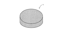
- FIG. 1 is an overall view showing a permanent magnet according to the present invention.
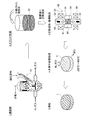
- FIG. 2 is an enlarged schematic view showing the vicinity of the grain boundary of the permanent magnet according to the present invention.
- FIG. 3 is an explanatory view showing a manufacturing process in the first method for manufacturing a permanent magnet according to the present invention.
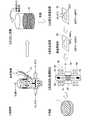
- FIG. 4 is an explanatory view showing a manufacturing process in the second method for manufacturing a permanent magnet according to the present invention.
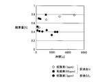
- FIG. 5 is a diagram showing a change in the amount of oxygen when the calcination treatment in hydrogen is performed and when it is not performed.
- FIG. 6 is a diagram showing the amount of carbon remaining in the permanent magnets of the permanent magnets of the example and the comparative example.
- FIG. 1 is an overall view showing a permanent magnet 1 according to the present invention.
- 1 has a cylindrical shape, the shape of the permanent magnet 1 varies depending on the shape of the cavity used for molding.
- an Nd—Fe—B magnet is used as the permanent magnet 1 according to the present invention.
- the permanent magnet 1 includes a main phase 11 that is a magnetic phase that contributes to the magnetization action, and a low-melting R-rich phase 12 that is nonmagnetic and concentrated with rare earth elements (R is a rare earth element Nd). , Pr, Dy, and Tb).
- FIG. 2 is an enlarged view showing Nd magnet particles constituting the permanent magnet 1.
- the main phase 11 is in a state in which the Nd 2 Fe 14 B intermetallic compound phase (Fe may be partially substituted with Co) having a stoichiometric composition occupies a high volume ratio.
- the R-rich phase 12 has an intermetallic compound phase (for example, R 2.0 ⁇ ) having a higher R composition ratio than R 2 Fe 14 B (Fe may be partially substituted with Co), which is also a stoichiometric composition. 3.0 Fe 14 B intermetallic compound phase).
- the R-rich phase 12 contains Cu or Al for improving magnetic characteristics as will be described later.
- the R-rich phase 12 plays the following role. (1) The melting point is low (about 600 ° C.), it becomes a liquid phase during sintering, and contributes to increasing the density of the magnet, that is, improving the magnetization. (2) Eliminate grain boundary irregularities, reduce reverse domain nucleation sites and increase coercivity. (3) The main phase is magnetically insulated to increase the coercive force. Accordingly, if the dispersion state of the R-rich phase 12 in the sintered permanent magnet 1 is poor, local sintering failure and magnetism decrease may be caused. It is important that is uniformly dispersed.
- ⁇ Fe is generated in the sintered alloy.
- the cause is that when a permanent magnet is manufactured using a magnet raw material alloy having a content based on the stoichiometric composition, the rare earth element is combined with oxygen during the manufacturing process, and the rare earth element is insufficient with respect to the stoichiometric composition. It becomes a state. Furthermore, if ⁇ Fe remains in the magnet after sintering, the magnetic properties of the magnet are reduced.
- the content of all rare earth elements including Nd and R in the permanent magnet 1 is preferably 0.1 wt% to 10.0 wt%, more preferably the content based on the stoichiometric composition (26.7 wt%). Is preferably within a range of 0.1 wt% to 5.0 wt%. Specifically, the content of each component is Nd ⁇ R: 25 to 37 wt%, B: 1 to 2 wt%, and Fe (electrolytic iron): 60 to 75 wt%.
- the R-rich phase 12 can be uniformly dispersed in the sintered permanent magnet 1. Moreover, even if the rare earth element is combined with oxygen in the manufacturing process, it is possible to suppress the production of ⁇ Fe in the sintered permanent magnet 1 without the rare earth element being insufficient with respect to the stoichiometric composition. It becomes possible.
- the content of the rare earth element in the permanent magnet 1 is less than the above range, the R-rich phase 12 is hardly formed. Moreover, the production
- the composition of the rare earth element in the permanent magnet 1 is larger than the above range, the increase in coercive force is slowed and the residual magnetic flux density is lowered, which is not practical.
- the R-rich phase 12 can be uniformly dispersed in the sintered permanent magnet 1.
- the addition of Cu or Al to the R-rich phase 12 is performed by adding an organometallic compound containing Cu or Al before forming a pulverized magnet powder as described later. Specifically, by adding an organometallic compound containing Cu or Al, Cu or Al in the organometallic compound is uniformly attached to the surface of the Nd magnet particles by wet dispersion. By sintering the magnet powder in this state, Cu or Al in the organometallic compound uniformly adhered to the surface of the Nd magnet particles is unevenly distributed in the grain boundary of the main phase 11, that is, the R-rich phase 12.
- M- (OR) x (wherein M is Cu or Al.
- R is a hydrocarbon substituent, and may be linear or branched.
- An organic metal compound for example, aluminum ethoxide, etc.
- Cu or Al represented by any integer is added to an organic solvent and mixed with the magnet powder in a wet state.
- the organometallic compound containing Cu or Al can be dispersed in an organic solvent, and the organometallic compound containing Cu or Al can be efficiently attached to the particle surfaces of the Nd magnet particles.
- M- (OR) x (wherein M is Cu or Al. R is a substituent composed of hydrocarbon, which may be linear or branched. X is an arbitrary integer.)
- M- (OR) n M: metal element, R: organic group, n: valence of metal or metalloid.
- W, Mo, V, Nb, Ta, Ti, Zr, Ir, Fe, Co, Ni, Cu, Zn, Cd, Al, Ga, In, Ge, Sb, Y, lanthanide, etc. are mentioned.
- Cu or Al is particularly used.
- alkoxide is not particularly limited, and examples thereof include methoxide, ethoxide, propoxide, isopropoxide, butoxide, alkoxide having 4 or more carbon atoms, and the like.
- those having a low molecular weight are used for the purpose of suppressing residual coal by low-temperature decomposition as described later.
- methoxide having 1 carbon is easily decomposed and difficult to handle, ethoxide, methoxide, isopropoxide, propoxide, butoxide, etc., which are alkoxides having 2 to 6 carbon atoms contained in R, are used. It is preferable.
- M- (OR) x (wherein M is Cu or Al.
- R is an alkyl group, and may be linear or branched, particularly as an organometallic compound added to the magnet powder. Is an arbitrary integer.
- M- (OR) x (wherein M is Cu or Al, and R is an alkyl group having 2 to 6 carbon atoms). It may be linear or branched, and x is an arbitrary integer).
- the crystal grain size D of the main phase 11 is desirably 0.1 ⁇ m to 5.0 ⁇ m.
- the thickness d of the R-rich phase 12 is 1 nm to 500 nm, preferably 2 nm to 200 nm.
- Dy or Tb can be unevenly distributed at the grain boundaries of the magnet particles. As a result, it is possible to improve the coercive force due to Dy and Tb.
- FIG. 3 is an explanatory view showing a manufacturing process in the first manufacturing method of the permanent magnet 1 according to the present invention.
- an ingot made of a predetermined fraction of Nd—Fe—B (eg, Nd: 32.7 wt%, Fe (electrolytic iron): 65.96 wt%, B: 1.34 wt%) is manufactured.
- the Nd content in the ingot is 0.1 wt% to 10.0 wt%, more preferably 0.1 wt% to 5.0 wt%, more than the content based on the stoichiometric composition (26.7 wt%).
- a small amount of Dy or Tb may be included to improve the coercive force.
- the ingot is roughly pulverized to a size of about 200 ⁇ m by a stamp mill or a crusher. Alternatively, the ingot is melted, flakes are produced by strip casting, and coarsely pulverized by hydrogen crushing.
- the coarsely pulverized magnet powder is either (a) in an atmosphere made of an inert gas such as nitrogen gas, Ar gas, or He gas having substantially 0% oxygen content, or (b) having an oxygen content of 0.0001.
- the oxygen concentration of substantially 0% is not limited to the case where the oxygen concentration is completely 0%, but may contain oxygen in such an amount that a very small amount of oxide film is formed on the surface of the fine powder. Means good.
- an organometallic compound solution to be added to the fine powder finely pulverized by the jet mill 41 is prepared.
- an organometallic compound containing Cu or Al is added in advance to the organometallic compound solution and dissolved.
- the organometallic compound to be dissolved is M- (OR) x (wherein M is Cu or Al, R is any alkyl group having 2 to 6 carbon atoms, which may be linear or branched) It is desirable to use an organic metal compound (for example, aluminum ethoxide) corresponding to x.
- the amount of the organometallic compound containing Cu or Al to be dissolved is not particularly limited, but the content of Cu or Al in the sintered magnet is 0.001 wt% to 10 wt%, preferably 0.01 wt% to 5 wt%. It is preferable that the amount is as follows.
- the organometallic compound solution is added to the fine powder classified by the jet mill 41.
- the slurry 42 in which the fine powder of the magnet raw material and the organometallic compound solution are mixed is generated.
- the addition of the organometallic compound solution is performed in an atmosphere made of an inert gas such as nitrogen gas, Ar gas, or He gas.
- the produced slurry 42 is dried in advance by vacuum drying or the like before molding, and the dried magnet powder 43 is taken out. Thereafter, the dried magnet powder is compacted into a predetermined shape by the molding device 50.
- a dry method in which the dried fine powder is filled into the cavity
- a wet method in which the powder is filled into the cavity after slurrying with a solvent or the like.
- the dry method is used. Illustrate.
- the organometallic compound solution can be volatilized in the firing stage after molding.
- the molding apparatus 50 includes a cylindrical mold 51, a lower punch 52 that slides up and down with respect to the mold 51, and an upper punch 53 that also slides up and down with respect to the mold 51. And a space surrounded by them constitutes the cavity 54.
- the molding apparatus 50 has a pair of magnetic field generating coils 55 and 56 disposed above and below the cavity 54, and applies magnetic field lines to the magnet powder 43 filled in the cavity 54.
- the applied magnetic field is, for example, 1 MA / m.
- the dried magnet powder 43 is filled into the cavity 54. Thereafter, the lower punch 52 and the upper punch 53 are driven, and pressure is applied in the direction of the arrow 61 to the magnetic powder 43 filled in the cavity 54 to perform molding. Simultaneously with the pressurization, a pulse magnetic field is applied to the magnetic powder 43 filled in the cavity 54 by the magnetic field generating coils 55 and 56 in the direction of the arrow 62 parallel to the pressurization direction. Thereby orienting the magnetic field in the desired direction. Note that the direction in which the magnetic field is oriented needs to be determined in consideration of the magnetic field direction required for the permanent magnet 1 formed from the magnet powder 43.
- the slurry when using the wet method, the slurry may be injected while applying a magnetic field to the cavity 54, and wet molding may be performed by applying a magnetic field stronger than the initial magnetic field during or after the injection. Further, the magnetic field generating coils 55 and 56 may be arranged so that the application direction is perpendicular to the pressing direction.
- the compact 71 formed by compacting is held in hydrogen by holding it in a hydrogen atmosphere at 200 ° C. to 900 ° C., more preferably 400 ° C. to 900 ° C. (eg 600 ° C.) for several hours (eg 5 hours).
- the amount of hydrogen supplied during calcination is 5 L / min.
- decarbonization is performed in which the organometallic compound is thermally decomposed to reduce the amount of carbon in the calcined body.
- the calcination treatment in hydrogen is performed under the condition that the carbon amount in the calcined body is 0.2 wt% or less, more preferably 0.1 wt% or less. Accordingly, the entire permanent magnet 1 can be densely sintered by the subsequent sintering process, and the residual magnetic flux density and coercive force are not reduced.
- the molded body 71 calcined by the above-described calcining treatment in hydrogen has a problem that NdH 3 exists and is easily combined with oxygen.
- the molded body 71 is preliminarily hydrogenated. Since it moves to the below-mentioned baking, without making it contact with external air after baking, a dehydrogenation process becomes unnecessary. During the firing, hydrogen in the molded body is released.
- the sintering process which sinters the molded object 71 calcined by the calcination process in hydrogen is performed.
- a sintering method of the molded body 71 it is also possible to use pressure sintering which sinters in a state where the molded body 71 is pressed in addition to general vacuum sintering.
- the temperature is raised to about 800 ° C. to 1080 ° C. at a predetermined rate of temperature rise and held for about 2 hours. During this time, vacuum firing is performed, but the degree of vacuum is preferably 10 ⁇ 4 Torr or less. Thereafter, it is cooled and heat treated again at 600 ° C. to 1000 ° C. for 2 hours.
- the permanent magnet 1 is manufactured as a result of sintering.
- pressure sintering examples include hot press sintering, hot isostatic pressing (HIP) sintering, ultrahigh pressure synthetic sintering, gas pressure sintering, and discharge plasma (SPS) sintering.
- HIP hot isostatic pressing
- SPS discharge plasma
- the SPS is uniaxial pressure sintering that pressurizes in a uniaxial direction and is sintered by current sintering. Sintering is preferably used.
- FIG. 4 is an explanatory view showing a manufacturing process in the second manufacturing method of the permanent magnet 1 according to the present invention.
- the process until the slurry 42 is generated is the same as the manufacturing process in the first manufacturing method already described with reference to FIG.
- the produced slurry 42 is dried in advance by vacuum drying or the like before molding, and the dried magnet powder 43 is taken out. Thereafter, the dried magnet powder 43 is calcined in hydrogen by holding it in a hydrogen atmosphere at 200 ° C. to 900 ° C., more preferably 400 ° C. to 900 ° C. (eg 600 ° C.) for several hours (eg 5 hours).
- the amount of hydrogen supplied during calcination is 5 L / min.
- decarbonization is performed in which the remaining organometallic compound is thermally decomposed to reduce the amount of carbon in the calcined body.
- the calcination treatment in hydrogen is performed under the condition that the carbon amount in the calcined body is 0.2 wt% or less, more preferably 0.1 wt% or less. Accordingly, the entire permanent magnet 1 can be densely sintered by the subsequent sintering process, and the residual magnetic flux density and coercive force are not reduced.
- dehydrogenation treatment is performed by holding the powder-like calcined body 82 calcined by calcination in hydrogen at 200 to 600 ° C., more preferably at 400 to 600 ° C. for 1 to 3 hours in a vacuum atmosphere. I do.
- the degree of vacuum is preferably 0.1 Torr or less.
- FIG. 5 shows the magnet powder with respect to the exposure time when the Nd magnet powder subjected to the calcination treatment in hydrogen and the Nd magnet powder not subjected to the calcination treatment in hydrogen are respectively exposed to an atmosphere having an oxygen concentration of 7 ppm and an oxygen concentration of 66 ppm. It is the figure which showed the amount of oxygen in.
- the oxygen content in the magnet powder increases from 0.4% to 0.8% in about 1000 seconds.
- the powder-like calcined body 82 subjected to the dehydrogenation treatment is compacted into a predetermined shape by the molding apparatus 50.
- the details of the molding apparatus 50 are the same as the manufacturing steps in the first manufacturing method already described with reference to FIG.
- a sintering process for sintering the formed calcined body 82 is performed.
- the sintering process is performed by vacuum sintering, pressure sintering, or the like, as in the first manufacturing method described above. Since the details of the sintering conditions are the same as those in the manufacturing process in the first manufacturing method already described, description thereof will be omitted. And the permanent magnet 1 is manufactured as a result of sintering.
- the first manufacturing method in which the magnet particles after molding are calcined in hydrogen are used.
- the pyrolysis of the organometallic compound can be more easily performed on the entire magnet particle. That is, it becomes possible to more reliably reduce the amount of carbon in the calcined body as compared with the first manufacturing method.
- the molded body 71 moves to firing without being exposed to the outside air after hydrogen calcination, so that a dehydrogenation step is unnecessary. Therefore, the manufacturing process can be simplified as compared with the second manufacturing method.
- the dehydrogenation step is not necessary when the firing is performed without contact with the outside air after the hydrogen calcination.
- the alloy composition of the neodymium magnet powder of the example is a ratio of Nd rather than a fraction based on the stoichiometric composition (Nd: 26.7 wt%, Fe (electrolytic iron): 72.3 wt%, B: 1.0 wt%).
- Nd / Fe / B 32.7 / 65.96 / 1.34 at wt%.
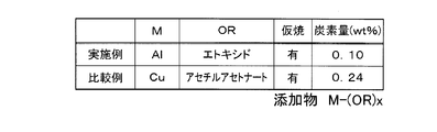
- 5 wt% of aluminum ethoxide was added to the pulverized neodymium magnet powder as an organometallic compound containing Cu or Al. The calcination treatment was performed by holding the magnet powder before molding at 600 ° C.
- the organometallic compound to be added was copper acetylacetonate. Other conditions are the same as in the example.
- FIG. 6 is a graph showing the carbon content [wt%] in the permanent magnets of the permanent magnets of the example and the comparative example. As shown in FIG. 6, it can be seen that the amount of carbon remaining in the magnet particles can be greatly reduced in the example as compared with the comparative example. In particular, in the examples, the amount of carbon remaining in the magnet particles can be 0.2 wt% or less, more specifically 0.1 wt% or less.
- M- (OR) x (wherein M is Cu or Al.
- R is an alkyl group, which may be linear or branched.
- X is an arbitrary integer. It can be seen that the amount of carbon in the magnet particles can be greatly reduced when the organometallic compound represented by (2) is added as compared with the case where the other organometallic compound is added. That is, the organometallic compound to be added is M- (OR) x (wherein M is Cu or Al. R is a substituent composed of hydrocarbon, which may be linear or branched. It is understood that decarbonization can be easily carried out in the calcination treatment in hydrogen.
- the organometallic compound to be added when an organometallic compound composed of an alkyl group having 2 to 6 carbon atoms is used as the organometallic compound to be added, the organometallic compound is thermally decomposed at a low temperature when the magnet powder is calcined in a hydrogen atmosphere. It becomes possible. Thereby, the thermal decomposition of the organometallic compound can be more easily performed on the entire magnet particle.
- M- (OR) x (where M is Cu or Al) with respect to the fine powder of the pulverized neodymium magnet.
- R is a hydrocarbon substituent, which may be linear or branched.
- X is an arbitrary integer.
- a magnet to which an organometallic compound is added is calcined in a hydrogen atmosphere before sintering, so that the organometallic compound is thermally decomposed and carbon contained in the magnet particles is preliminarily burned out (the amount of carbon is reduced).
- the carbide is hardly formed in the sintering process. As a result, it is possible to sinter the entire magnet densely without generating voids between the main phase and the grain boundary phase of the sintered magnet, and to prevent the coercive force from being lowered. . Further, ⁇ Fe is not precipitated in the main phase of the magnet after sintering, and the magnet characteristics are not greatly deteriorated.
- the magnet powder or molded body can be produced in a hydrogen atmosphere.
- the thermal decomposition of the organometallic compound can be more easily performed on the entire magnet powder or the entire compact.
- the step of calcining the magnet powder or the molded body is performed by holding the molded body for a predetermined time in a temperature range of 200 ° C. to 900 ° C., more preferably 400 ° C.
- the amount of carbon remaining in the magnet after sintering is 0.2 wt% or less, more preferably 0.1 wt% or less, so that no voids are generated between the main phase of the magnet and the grain boundary phase, and It becomes possible to make the whole magnet into a densely sintered state, and it is possible to prevent the residual magnetic flux density from being lowered. Further, ⁇ Fe is not precipitated in the main phase of the magnet after sintering, and the magnet characteristics are not greatly deteriorated.
- the pyrolysis of the organometallic compound is performed in comparison with the case of calcining the molded magnet particles. This can be done more easily for the whole particle. That is, the amount of carbon in the calcined body can be reduced more reliably. Further, by performing the dehydrogenation treatment after the calcination treatment, the activity of the calcined body activated by the calcination treatment can be reduced. As a result, the magnet particles are prevented from being combined with oxygen thereafter, and the residual magnetic flux density and coercive force are not reduced. In addition, since the step of performing the dehydrogenation process is performed by holding the magnet powder in a temperature range of 200 ° C.
- NdH 3 having high activity is contained in the Nd-based magnet that has been subjected to the hydrogen calcining process. Even if is generated, it is possible to shift to NdH 2 having low activity without leaving any.
- this invention is not limited to the said Example, Of course, various improvement and deformation
- the pulverization conditions, kneading conditions, calcination conditions, dehydrogenation conditions, sintering conditions, etc. of the magnet powder are not limited to the conditions described in the above examples.
- organometallic compound added to the magnet powder is used as the organometallic compound added to the magnet powder, but M- (OR) x (wherein M is Cu or Al. R is a substituent composed of hydrocarbon).
- organometallic compound represented by the formula (x) other organometallic compounds may be used.
- an organometallic compound composed of an alkyl group having 7 or more carbon atoms or an organometallic compound composed of a substituent composed of a hydrocarbon other than an alkyl group may be used.
Abstract
Description
(1)融点が低く(約600℃)、焼結時に液相となり、磁石の高密度化、即ち磁化の向上に寄与する。(2)粒界の凹凸を無くし、逆磁区のニュークリエーションサイトを減少させ保磁力を高める。(3)主相を磁気的に絶縁し保磁力を増加する。
先ず、本発明に係る永久磁石1の構成について説明する。図1は本発明に係る永久磁石1を示した全体図である。尚、図1に示す永久磁石1は円柱形状を備えるが、永久磁石1の形状は成形に用いるキャビティの形状によって変化する。
本発明に係る永久磁石1としては例えばNd-Fe-B系磁石を用いる。また、図2に示すように、永久磁石1は磁化作用に寄与する磁性相である主相11と、非磁性で希土類元素の濃縮した低融点のRリッチ相12(Rは希土類元素であるNd、Pr、Dy、Tbの内、少なくとも一種を含む。)とが共存する合金である。図2は永久磁石1を構成するNd磁石粒子を拡大して示した図である。
(1)融点が低く(約600℃)、焼結時に液相となり、磁石の高密度化、即ち磁化の向上に寄与する。(2)粒界の凹凸を無くし、逆磁区のニュークリエーションサイトを減少させ保磁力を高める。(3)主相を磁気的に絶縁し保磁力を増加する。
従って、焼結後の永久磁石1中におけるRリッチ相12の分散状態が悪いと、局部的な焼結不良、磁性の低下をまねくため、焼結後の永久磁石1中にはRリッチ相12が均一に分散していることが重要となる。
次に、本発明に係る永久磁石1の第1の製造方法について図3を用いて説明する。図3は本発明に係る永久磁石1の第1の製造方法における製造工程を示した説明図である。
また、成形装置50には一対の磁界発生コイル55、56がキャビティ54の上下位置に配置されており、磁力線をキャビティ54に充填された磁石粉末43に印加する。印加させる磁場は例えば1MA/mとする。
また、湿式法を用いる場合には、キャビティ54に磁場を印加しながらスラリーを注入し、注入途中又は注入終了後に、当初の磁場より強い磁場を印加して湿式成形しても良い。また、加圧方向に対して印加方向が垂直となるように磁界発生コイル55、56を配置しても良い。
次に、本発明に係る永久磁石1の他の製造方法である第2の製造方法について図4を用いて説明する。図4は本発明に係る永久磁石1の第2の製造方法における製造工程を示した説明図である。
図5は水素中仮焼処理をしたNd磁石粉末と水素中仮焼処理をしていないNd磁石粉末とを、酸素濃度7ppm及び酸素濃度66ppmの雰囲気にそれぞれ暴露した際に、暴露時間に対する磁石粉末内の酸素量を示した図である。図5に示すように水素中仮焼処理した磁石粉末は、高酸素濃度66ppm雰囲気におかれると、約1000secで磁石粉末内の酸素量が0.4%から0.8%まで上昇する。また、低酸素濃度7ppm雰囲気におかれても、約5000secで磁石粉末内の酸素量が0.4%から同じく0.8%まで上昇する。そして、Ndが酸素と結び付くと、残留磁束密度や保磁力の低下の原因となる。
そこで、上記脱水素処理では、水素中仮焼処理によって生成された仮焼体82中のNdH3(活性度大)を、NdH3(活性度大)→NdH2(活性度小)へと段階的に変化させることによって、水素仮焼中処理により活性化された仮焼体82の活性度を低下させる。それによって、水素中仮焼処理によって仮焼された仮焼体82をその後に大気中へと移動させた場合であっても、Ndが酸素と結び付くことを防止し、残留磁束密度や保磁力を低下させることが無い。
一方、第1の製造方法では、成形体71は水素仮焼後に外気と触れさせることなく焼成に移るため、脱水素工程は不要となる。従って、前記第2の製造方法と比較して製造工程を簡略化することが可能となる。但し、前記第2の製造方法においても、水素仮焼後に外気と触れさせることがなく焼成を行う場合には、脱水素工程は不要となる。
(実施例)
実施例のネオジム磁石粉末の合金組成は、化学量論組成に基づく分率(Nd:26.7wt%、Fe(電解鉄):72.3wt%、B:1.0wt%)よりもNdの比率を高くし、例えばwt%でNd/Fe/B=32.7/65.96/1.34とする。また、粉砕したネオジム磁石粉末にCu又はAlを含む有機金属化合物としてアルミニウムエトキシドを5wt%添加した。また、仮焼処理は、成形前の磁石粉末を水素雰囲気において600℃で5時間保持することにより行った。そして、仮焼中の水素の供給量は5L/minとする。また、成形された仮焼体の焼結はSPS焼結により行った。尚、他の工程は上述した[永久磁石の製造方法2]と同様の工程とする。
添加する有機金属化合物を銅アセチルアセトナートとした。他の条件は実施例と同様である。
図6は実施例と比較例の永久磁石の永久磁石中の残存炭素量[wt%]をそれぞれ示した図である。
図6に示すように、実施例は比較例と比較して磁石粒子中に残存する炭素量を大きく低減させることができることが分かる。特に、実施例では、磁石粒子中に残存する炭素量を0.2wt%以下、より具体的には0.1wt%以下とすることができる。
また、有機金属化合物が添加された磁石を、焼結前に水素雰囲気で仮焼することにより、有機金属化合物を熱分解させて磁石粒子中に含有する炭素を予め焼失(炭素量を低減)させることができ、焼結工程でカーバイドがほとんど形成されることがない。その結果、焼結後の磁石の主相と粒界相との間に空隙を生じさせることなく、また、磁石全体を緻密に焼結することが可能となり、保磁力が低下することを防止できる。また、焼結後の磁石の主相内にαFeが析出することなく、磁石特性を大きく低下させることがない。
また、特に添加する有機金属化合物としてアルキル基から構成される有機金属化合物、より好ましくは炭素数2~6のアルキル基から構成される有機金属化合物を用いれば、水素雰囲気で磁石粉末や成形体を仮焼する際に、低温で有機金属化合物の熱分解を行うことが可能となる。それによって、有機金属化合物の熱分解を磁石粉末全体や成形体全体に対してより容易に行うことができる。
更に、磁石粉末や成形体を仮焼する工程は、特に200℃~900℃、より好ましくは400℃~900℃の温度範囲で成形体を所定時間保持することにより行うので、磁石粒子中に含有する炭素を必要量以上焼失させることができる。
その結果、焼結後に磁石に残存する炭素量が0.2wt%以下、より好ましくは0.1wt%以下となるので、磁石の主相と粒界相との間に空隙が生じることなく、また、磁石全体を緻密に焼結した状態とすることが可能となり、残留磁束密度が低下することを防止できる。また、焼結後の磁石の主相内にαFeが析出することなく、磁石特性を大きく低下させることがない。
また、特に第2の製造方法では、粉末状の磁石粒子に対して仮焼を行うので、成形後の磁石粒子に対して仮焼を行う場合と比較して、有機金属化合物の熱分解を磁石粒子全体に対してより容易に行うことができる。即ち、仮焼体中の炭素量をより確実に低減させることが可能となる。また、仮焼処理後に脱水素処理を行うことによって、仮焼処理により活性化された仮焼体の活性度を低下させることができる。それにより、その後に磁石粒子が酸素と結び付くことを防止し、残留磁束密度や保磁力を低下させることが無い。
また、脱水素処理を行う工程は、200℃~600℃の温度範囲で磁石粉末を所定時間保持することにより行うので、水素仮焼中処理を行ったNd系磁石中に活性度の高いNdH3が生成された場合であっても、残さずに活性度の低いNdH2へと移行させることが可能となる。
また、磁石粉末の粉砕条件、混練条件、仮焼条件、脱水素条件、焼結条件などは上記実施例に記載した条件に限られるものではない。
また、水素中仮焼処理や脱水素工程については省略しても良い。
11 主相
12 Rリッチ相
Claims (7)
- 磁石原料を磁石粉末に粉砕する工程と、
前記粉砕された磁石粉末に以下の構造式
M-(OR)x
(式中、MはCu又はAlである。Rは炭化水素からなる置換基であり、直鎖でも分枝でも良い。xは任意の整数である。)
で表わされる有機金属化合物を添加することにより、前記磁石粉末の粒子表面に前記有機金属化合物を付着させる工程と、
前記有機金属化合物が粒子表面に付着された前記磁石粉末を成形することにより成形体を形成する工程と、
前記成形体を焼結する工程と、により製造されることを特徴とする永久磁石。 - 前記有機金属化合物を形成する金属が、焼結後に前記永久磁石の粒界に偏在していることを特徴とする請求項1に記載の永久磁石。
- 前記構造式中のRは、アルキル基であることを特徴とする請求項1又は請求項2に記載の永久磁石。
- 前記構造式中のRは、炭素数2~6のアルキル基のいずれかであることを特徴とする請求項3に記載の永久磁石。
- 磁石原料を磁石粉末に粉砕する工程と、
前記粉砕された磁石粉末に以下の構造式
M-(OR)x
(式中、MはCu又はAlである。Rは炭化水素からなる置換基であり、直鎖でも分枝でも良い。xは任意の整数である。)
で表わされる有機金属化合物を添加することにより、前記磁石粉末の粒子表面に前記有機金属化合物を付着させる工程と、
前記有機金属化合物が粒子表面に付着された前記磁石粉末を成形することにより成形体を形成する工程と、
前記成形体を焼結する工程と、を有することを特徴とする永久磁石の製造方法。 - 前記構造式中のRは、アルキル基であることを特徴とする請求項5に記載の永久磁石の製造方法。
- 前記構造式中のRは、炭素数2~6のアルキル基のいずれかであることを特徴とする請求項6に記載の永久磁石の製造方法。
Priority Applications (4)
| Application Number | Priority Date | Filing Date | Title |
|---|---|---|---|
| CN201180003983.9A CN102576590B (zh) | 2010-03-31 | 2011-03-28 | 永久磁铁及永久磁铁的制造方法 |
| KR1020127007160A KR101165938B1 (ko) | 2010-03-31 | 2011-03-28 | 영구 자석 및 영구 자석의 제조 방법 |
| EP11765490.5A EP2506270B1 (en) | 2010-03-31 | 2011-03-28 | Permanent magnet and manufacturing method for permanent magnet |
| US13/499,442 US8480818B2 (en) | 2010-03-31 | 2011-03-28 | Permanent magnet and manufacturing method thereof |
Applications Claiming Priority (2)
| Application Number | Priority Date | Filing Date | Title |
|---|---|---|---|
| JP2010082235 | 2010-03-31 | ||
| JP2010-082235 | 2010-03-31 |
Publications (1)
| Publication Number | Publication Date |
|---|---|
| WO2011125590A1 true WO2011125590A1 (ja) | 2011-10-13 |
Family
ID=44762539
Family Applications (1)
| Application Number | Title | Priority Date | Filing Date |
|---|---|---|---|
| PCT/JP2011/057571 WO2011125590A1 (ja) | 2010-03-31 | 2011-03-28 | 永久磁石及び永久磁石の製造方法 |
Country Status (7)
| Country | Link |
|---|---|
| US (1) | US8480818B2 (ja) |
| EP (1) | EP2506270B1 (ja) |
| JP (1) | JP4923149B2 (ja) |
| KR (1) | KR101165938B1 (ja) |
| CN (1) | CN102576590B (ja) |
| TW (1) | TW201212057A (ja) |
| WO (1) | WO2011125590A1 (ja) |
Families Citing this family (4)
| Publication number | Priority date | Publication date | Assignee | Title |
|---|---|---|---|---|
| JP5011420B2 (ja) * | 2010-05-14 | 2012-08-29 | 日東電工株式会社 | 永久磁石及び永久磁石の製造方法 |
| WO2014204106A1 (ko) * | 2013-06-18 | 2014-12-24 | 고려대학교 산학협력단 | 영구 자석의 제조 방법 |
| KR101527324B1 (ko) * | 2013-06-18 | 2015-06-09 | 고려대학교 산학협력단 | 영구 자석의 제조 방법 |
| CN113030113A (zh) * | 2020-04-13 | 2021-06-25 | 宁波守正磁电有限公司 | 磁片连续送料视觉检测设备 |
Citations (4)
| Publication number | Priority date | Publication date | Assignee | Title |
|---|---|---|---|---|
| JPS6468903A (en) * | 1987-09-09 | 1989-03-15 | Fuji Electrochemical Co Ltd | Manufacture of permanent magnet |
| JPH01247502A (ja) * | 1988-03-30 | 1989-10-03 | Tosoh Corp | 強磁性鉄粉の表面処理方法 |
| JPH05271708A (ja) * | 1992-03-27 | 1993-10-19 | Sumitomo Metal Mining Co Ltd | 射出成形用組成物 |
| JP3728316B2 (ja) | 2004-01-08 | 2005-12-21 | Tdk株式会社 | R−t−b系希土類永久磁石 |
Family Cites Families (9)
| Publication number | Priority date | Publication date | Assignee | Title |
|---|---|---|---|---|
| EP1260995B1 (en) * | 1993-11-02 | 2005-03-30 | TDK Corporation | Preparation of permanent magnet |
| US5641363A (en) * | 1993-12-27 | 1997-06-24 | Tdk Corporation | Sintered magnet and method for making |
| JP2002363607A (ja) | 2001-06-13 | 2002-12-18 | Sumitomo Metal Mining Co Ltd | 希土類系磁性粉末、その製造方法及びこれを用いた磁石 |
| US7311788B2 (en) * | 2002-09-30 | 2007-12-25 | Tdk Corporation | R-T-B system rare earth permanent magnet |
| CN103295713B (zh) * | 2006-01-31 | 2016-08-10 | 日立金属株式会社 | R-Fe-B类稀土烧结磁铁 |
| US8128759B2 (en) * | 2006-12-21 | 2012-03-06 | Ulvac, Inc. | Permanent magnet and method of manufacturing same |
| JP5509850B2 (ja) * | 2007-07-02 | 2014-06-04 | 日立金属株式会社 | R−Fe−B系希土類焼結磁石およびその製造方法 |
| JP5266523B2 (ja) * | 2008-04-15 | 2013-08-21 | 日東電工株式会社 | 永久磁石及び永久磁石の製造方法 |
| JP5331885B2 (ja) * | 2009-08-06 | 2013-10-30 | 株式会社東芝 | 永久磁石とそれを用いた可変磁束モータおよび発電機 |
-
2011
- 2011-03-28 EP EP11765490.5A patent/EP2506270B1/en not_active Not-in-force
- 2011-03-28 CN CN201180003983.9A patent/CN102576590B/zh not_active Expired - Fee Related
- 2011-03-28 WO PCT/JP2011/057571 patent/WO2011125590A1/ja active Application Filing
- 2011-03-28 KR KR1020127007160A patent/KR101165938B1/ko active IP Right Grant
- 2011-03-28 JP JP2011069065A patent/JP4923149B2/ja not_active Expired - Fee Related
- 2011-03-28 US US13/499,442 patent/US8480818B2/en not_active Expired - Fee Related
- 2011-03-31 TW TW100111450A patent/TW201212057A/zh not_active IP Right Cessation
Patent Citations (4)
| Publication number | Priority date | Publication date | Assignee | Title |
|---|---|---|---|---|
| JPS6468903A (en) * | 1987-09-09 | 1989-03-15 | Fuji Electrochemical Co Ltd | Manufacture of permanent magnet |
| JPH01247502A (ja) * | 1988-03-30 | 1989-10-03 | Tosoh Corp | 強磁性鉄粉の表面処理方法 |
| JPH05271708A (ja) * | 1992-03-27 | 1993-10-19 | Sumitomo Metal Mining Co Ltd | 射出成形用組成物 |
| JP3728316B2 (ja) | 2004-01-08 | 2005-12-21 | Tdk株式会社 | R−t−b系希土類永久磁石 |
Non-Patent Citations (1)
| Title |
|---|
| See also references of EP2506270A4 |
Also Published As
| Publication number | Publication date |
|---|---|
| TW201212057A (en) | 2012-03-16 |
| KR20120049346A (ko) | 2012-05-16 |
| CN102576590A (zh) | 2012-07-11 |
| EP2506270A1 (en) | 2012-10-03 |
| CN102576590B (zh) | 2014-04-02 |
| US8480818B2 (en) | 2013-07-09 |
| US20120182106A1 (en) | 2012-07-19 |
| JP2011228657A (ja) | 2011-11-10 |
| EP2506270A4 (en) | 2012-11-07 |
| TWI374460B (ja) | 2012-10-11 |
| EP2506270B1 (en) | 2014-12-03 |
| KR101165938B1 (ko) | 2012-07-20 |
| JP4923149B2 (ja) | 2012-04-25 |
Similar Documents
| Publication | Publication Date | Title |
|---|---|---|
| JP4923163B1 (ja) | 永久磁石及び永久磁石の製造方法 | |
| JP4865920B2 (ja) | 永久磁石及び永久磁石の製造方法 | |
| JP4865100B2 (ja) | 永久磁石及び永久磁石の製造方法 | |
| JP4923148B2 (ja) | 永久磁石及び永久磁石の製造方法 | |
| JP4865098B2 (ja) | 永久磁石及び永久磁石の製造方法 | |
| WO2011125592A1 (ja) | 永久磁石及び永久磁石の製造方法 | |
| JP4923147B2 (ja) | 永久磁石及び永久磁石の製造方法 | |
| JP4923151B2 (ja) | 永久磁石及び永久磁石の製造方法 | |
| JP4865097B2 (ja) | 永久磁石及び永久磁石の製造方法 | |
| JP4865099B2 (ja) | 永久磁石及び永久磁石の製造方法 | |
| JP4923149B2 (ja) | 永久磁石及び永久磁石の製造方法 | |
| WO2011125593A1 (ja) | 永久磁石及び永久磁石の製造方法 | |
| JP5908247B2 (ja) | 永久磁石の製造方法 | |
| JP5501826B2 (ja) | 希土類焼結磁石の製造方法 | |
| JP4923150B2 (ja) | 永久磁石及び永久磁石の製造方法 | |
| JP5501824B2 (ja) | R−Fe−B系永久磁石 | |
| JP5501836B2 (ja) | R−Fe−B系永久磁石 |
Legal Events
| Date | Code | Title | Description |
|---|---|---|---|
| WWE | Wipo information: entry into national phase |
Ref document number: 201180003983.9 Country of ref document: CN |
|
| 121 | Ep: the epo has been informed by wipo that ep was designated in this application |
Ref document number: 11765490 Country of ref document: EP Kind code of ref document: A1 |
|
| ENP | Entry into the national phase |
Ref document number: 20127007160 Country of ref document: KR Kind code of ref document: A |
|
| WWE | Wipo information: entry into national phase |
Ref document number: 2866/CHENP/2012 Country of ref document: IN Ref document number: 2011765490 Country of ref document: EP |
|
| WWE | Wipo information: entry into national phase |
Ref document number: 13499442 Country of ref document: US |
|
| NENP | Non-entry into the national phase |
Ref country code: DE |