WO2011125558A1 - 曲げ加工性に優れたCu-Ni-Si系合金 - Google Patents
曲げ加工性に優れたCu-Ni-Si系合金 Download PDFInfo
- Publication number
- WO2011125558A1 WO2011125558A1 PCT/JP2011/057441 JP2011057441W WO2011125558A1 WO 2011125558 A1 WO2011125558 A1 WO 2011125558A1 JP 2011057441 W JP2011057441 W JP 2011057441W WO 2011125558 A1 WO2011125558 A1 WO 2011125558A1
- Authority
- WO
- WIPO (PCT)
- Prior art keywords
- surface layer
- bending
- rolling
- precipitates
- less
- Prior art date
- Legal status (The legal status is an assumption and is not a legal conclusion. Google has not performed a legal analysis and makes no representation as to the accuracy of the status listed.)
- Ceased
Links
Images


Classifications
-
- C—CHEMISTRY; METALLURGY
- C22—METALLURGY; FERROUS OR NON-FERROUS ALLOYS; TREATMENT OF ALLOYS OR NON-FERROUS METALS
- C22C—ALLOYS
- C22C9/00—Alloys based on copper
-
- C—CHEMISTRY; METALLURGY
- C22—METALLURGY; FERROUS OR NON-FERROUS ALLOYS; TREATMENT OF ALLOYS OR NON-FERROUS METALS
- C22C—ALLOYS
- C22C9/00—Alloys based on copper
- C22C9/06—Alloys based on copper with nickel or cobalt as the next major constituent
-
- C—CHEMISTRY; METALLURGY
- C22—METALLURGY; FERROUS OR NON-FERROUS ALLOYS; TREATMENT OF ALLOYS OR NON-FERROUS METALS
- C22F—CHANGING THE PHYSICAL STRUCTURE OF NON-FERROUS METALS AND NON-FERROUS ALLOYS
- C22F1/00—Changing the physical structure of non-ferrous metals or alloys by heat treatment or by hot or cold working
- C22F1/08—Changing the physical structure of non-ferrous metals or alloys by heat treatment or by hot or cold working of copper or alloys based thereon
-
- H—ELECTRICITY
- H01—ELECTRIC ELEMENTS
- H01B—CABLES; CONDUCTORS; INSULATORS; SELECTION OF MATERIALS FOR THEIR CONDUCTIVE, INSULATING OR DIELECTRIC PROPERTIES
- H01B1/00—Conductors or conductive bodies characterised by the conductive materials; Selection of materials as conductors
- H01B1/02—Conductors or conductive bodies characterised by the conductive materials; Selection of materials as conductors mainly consisting of metals or alloys
- H01B1/026—Alloys based on copper
Definitions
- the present invention relates to a high-strength copper alloy used for electronic materials such as lead frames and connectors, and terminals for in-vehicle connectors. More specifically, the present invention relates to a high-strength copper alloy exhibiting excellent bending workability and bending portion appearance that do not cause wrinkles or cracks in the bending portion appearance after bending.
- a Corson alloy (Cu—Ni—Si based copper alloy) having an excellent balance of strength, conductivity and bendability is used.
- the bendability is deteriorated, and those having good bendability are low in strength. Accordingly, various improvements have been made to achieve both strength and bendability.
- Patent Documents 1 and 2 in a Corson alloy containing a certain amount of a specific element, the tensile strength and bending strength are controlled by controlling the particle size and number of precipitates made of Ni and Si and the precipitates containing the specific element.
- a copper alloy excellent in workability and other stress relaxation resistance is disclosed.
- Patent Document 3 the surface of the Corson alloy is smoothed and a compressive residual stress is applied to counter the tensile stress caused by product bending, thereby suppressing the generation of cracks.
- the appearance of the bent part of the Corson alloy is inferior to that of phosphor bronze and is characterized by a rough skin. If a crack occurs in the terminal, the electrical conductivity and spring properties required for the terminal are lost, and the reliability of the product is impaired. Therefore, the appearance inspection of the bent part of the product is usually performed. However, for example, it is difficult to check the appearance of the bending part of the most advanced ultra-small terminal with the naked eye, and in the inspection process for checking the condition after the bending press, it is visually observed using a magnifying glass or by a CCD camera. We have to rely on jigs and machines, such as checking with surface inspection equipment.
- a Corson alloy used for a material for a microelectronic device is not limited as long as cracks do not occur in a bent portion, and a material with a small rough surface of the bent portion is required.
- MBR / t ratio between the minimum bending radius and the plate thickness that can be bent without generating cracks
- MBR / t ratio between the minimum bending radius and the plate thickness that can be bent without generating cracks
- MBR / t with the best bendability is 0.5 or more, so the wrinkle of the bent portion is considered to be large, and the connector connector is required to be subjected to severe bending and visual inspection.
- Patent Document 3 focuses on product surface roughness for the purpose of improving fatigue characteristics against repeated bending, but does not aim at improving the appearance of the bent portion after bending.
- the object of the present invention is to improve not only the excellent bendability of the Corson-based copper alloy, specifically the crack, but also the rough surface of the bent portion, which has not been noticed in the past, after bending of GW (good way). .
- the present inventors have eliminated the portion that is the starting point of non-uniform elongation such as foreign matter and defects from the vicinity of the surface, and the center portion of the plate thickness (described below) Machines that have the original tensile strength, 0.2% proof stress, spring limit value, etc., by suppressing the formation of shear bands on the surface layer (from the material surface to 1/6 depth of the plate thickness) compared to the portion other than the surface layer)
- the present invention was completed by discovering that the rough surface of the bent portion of the GW can be improved while maintaining the target characteristics.
- the present invention has the following configuration.
- the ratio Ss of the number Ss of shear band lines up to the depth hereinafter referred to as “surface layer”) and the number Sc of lines of shear bands other than the material surface layer (hereinafter referred to as “plate thickness central portion”)
- the present invention can provide a high-strength copper alloy exhibiting excellent bending workability suitable for a copper alloy for electronic materials such as terminals and connectors, and an appearance of a bent portion without wrinkles.
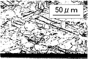
- FIG. It is an optical microscope photograph (800 times) which image
- FIG. It is the optical microscope photograph (800 times) which image
- Optical micrographs 200 times left, 400 times right, 400 times right taken of a plate thickness section parallel to the rolling direction after the bending property evaluation test of the alloy strips manufactured in Example 4 (top) and Comparative Example 34 (bottom). Times).
- Ni reacts with Si to form a compound having a Ni 2 Si composition and precipitates in the Cu matrix, suppressing the decrease in conductivity and greatly improving the strength.
- the amount of Ni added to the copper alloy of the present invention is 0.8 to 4.6% (mass%, the same shall apply hereinafter). If it is less than 0.8%, the precipitation amount is small and sufficient strength cannot be obtained. If it exceeds 50%, precipitates that do not contribute to strength improvement are produced during casting or hot working, and not only the strength corresponding to the amount added is obtained, but also hot workability and bending workability are adversely affected. It becomes coarse and protrudes from the end face of the lead frame, which deteriorates the adhesion of the noble metal plating.
- Si reacts with Ni without adversely affecting the electrical conductivity to form a compound having a Ni 2 Si composition. Accordingly, when the addition amount of Ni is determined, the optimum Si addition amount is determined.
- the amount of Si added to the copper alloy of the present invention is 0.3 to 1.6%. If it is less than 0.3%, sufficient strength cannot be obtained as in the case of Ni. Various problems similar to those of Ni occur.
- Mg Mg improves the stress relaxation properties, but is a component that degrades the heat-resistant peelability of the plating. If it exceeds 2.0 mass%, the heat-resistant peelability of the plating is lowered.
- Fe, Co, Cr, Mn Fe and Co react with Si to form silicide and precipitate, thereby contributing to strength improvement.
- Cr and Mn also have the effect of improving hot rollability. This is because these elements inevitably form a compound with sulfur present in the alloy because of their strong affinity with sulfur, reducing the segregation of sulfur to the ingot grain boundaries that cause hot rolling cracks. Because. The total amount of one or more of these elements is 2.0% or less, and if it exceeds 2.0%, the conductivity is lowered, which is not preferable.
- the non-uniform elongation tends to occur below the strain limit value corresponding to the original mechanical characteristics of the material, and the wrinkle of the bent portion tends to increase. Therefore, bending wrinkles can be reduced by reducing the starting points at which these non-uniform elongation occurs.
- Factors that serve as starting points for non-uniform elongation include roughness of the material surface and precipitates present on the surface layer. The surface roughness of the material can be reduced by conventional means such as surface polishing of the surface of the final rolling roll, but it alone cannot cope with the bending process required for the latest ultra-small terminals.
- Shear band in metal structure In general, copper alloys can be strengthened by adjusting the grain size (crystal refinement) of metal crystals, the amount of precipitates, grain size, and distribution (precipitation strengthening). It can also be strengthened by adjusting the degree of hot rolling (strengthening process). In rolling, a load applied by a rolling roll is applied from the vertical direction to a material in which tension is applied in the longitudinal direction, and the material is deformed (rolled). During this rolling, shear deformation locally concentrates, the crystal grain structure is deformed and broken, and a band-like structure called a shear band is formed regardless of the crystal orientation.
- the line of the shear band of the present invention is an angle of about 10 to 60 ° with the flat crystal grain structure aligned in parallel to the rolling direction, which is recognized when a sheet thickness section parallel to the rolling direction of the rolled material is observed.
- a line that intersects at. For example, in a portion surrounded by an ellipse in FIG. 2, it can be confirmed that a plurality of shear bands extending from the lower left to the upper right are arranged in parallel.
- the shear band is a structure in which deformation is locally concentrated, that is, a portion where dislocation density increases due to increased strain, and is less likely to be deformed than the surrounding structure. For this reason, in a material having a shear band, non-uniform elongation occurs starting from the shear band when bending is performed, and wrinkles and cracks occur when the non-uniform elongation reaches the surface. However, if the rolling process is not performed until the shear band is formed, the work cannot be strengthened and the required alloy strength cannot be achieved. Therefore, the product after the final cold rolling must have the shear band inherent. Yes.
- the present inventors paid attention to the distribution of the shear band, and found that the smaller the shear band near the surface of the material, the less likely the non-uniform elongation to reach the surface is, so that cracks and wrinkles are reduced. That is, when the strain embodied as a shear band is less in the surface layer than the central portion of the plate thickness, cracks and wrinkles are unlikely to occur during bending.
- the ratio Ss / Sc of the number Ss of shear band lines observed on the material surface layer after the final rolling and the number Sc of shear band lines at the center of the plate thickness (the portion other than the surface layer) is 1. If it is 0 or less, preferably 0.95 or less, the occurrence of bending wrinkles is reduced even during severe bending.
- the number of the shear band lines on the material surface layer after the final rolling is preferably 10/10000 ⁇ m 2 or less, more preferably 5/10000 ⁇ m 2 or less, the occurrence of bending wrinkles is reduced.
- the total degree of work in the final rolling is lowered and the work strengthening is not performed sufficiently, and there are few shear bands in the surface layer of the material or the center of the plate thickness, it is possible to obtain a high strength alloy strip of the present invention. Can not.
- the shear band is mechanically polished on a plate thickness section parallel to the rolling direction, immersed in an acidic aqueous solution such as dilute sulfuric acid or dilute nitric acid, and etched to reveal crystal grain boundaries and shear bands. It can be observed at a magnification of about 200 to 800 times using a microscope (see FIGS. 1 to 3).
- the line of the shear band is a line having a length of 5 ⁇ m or more that intersects the crystal grain boundary at one or more places with an inclination of about 10 to 60 ° with respect to the rolling direction.
- the normal size of the shear band is 1 ⁇ m or less in width and 5 to 30 ⁇ m in length.
- Shear bands are likely to occur in the portion where the strain accumulates. Strain tends to accumulate locally in the vicinity of the precipitate particles in a portion where the structure becomes discontinuous, that is, in a Corson alloy. Therefore, if the density of the precipitate particles is low, the localization of strain is suppressed, and a shear band is hardly generated.
- the “precipitate” of the present invention is a crystallized product generated during the solidification process during casting, oxides or sulfides generated by a reaction in the molten metal during melting, cooling process after ingot solidification, hot It is a general term for metal compounds such as precipitates that precipitate in the Cu matrix base material during rolling and after the solution treatment and cooling process and aging treatment. Accordingly, some of the precipitate particles are made of Ni and Si, and some of the particles are obtained by further adding an additive alloy element to the particles, and some of them do not contain either Ni or Si or both.
- the particle size and number of the precipitates can be observed at a magnification of about 200 to 2000 times using an FE-SEM (electrolytic emission scanning electron microscope) after the material is etched with an aqueous ferric chloride solution. Components were measured using particle analysis software and EDS (energy dispersive X-ray analysis), and particles composed of components different from the base material components were determined as precipitates. The particle size of each precipitate was measured and counted. Here, the diameter of the circle circumscribing the precipitate is defined as the particle size of the precipitate.
- the present invention is not limited by theory, in the surface layer from the surface of the material after aging treatment to 1/6 plate thickness depth, the number of precipitates having a particle diameter of 1 to 10 ⁇ m is 1.0 ⁇ 10 2 / if mm 2 or less, due to the low density of the precipitates as the starting point of shear bands occurrence, the occurrence of shear bands in the surface layer portion is reduced, wrinkles can also be reduced which occurs bend. On the other hand, when it exceeds 1.0 ⁇ 10 2 pieces / mm 2 , the generation of shear bands in the surface layer increases, and the wrinkles generated in the bent portion increase.
- the number of precipitates having a particle size of 1 to 10 ⁇ m in the surface layer is preferably 1 ⁇ 10 ⁇ 6 pieces / mm 2 or more, and if it is less than that, there is little precipitation as a whole material, and the effect of increasing the strength cannot be obtained.
- the conductivity tends to be low.
- the ratio Ns / Nc of the number Ns of precipitate particles having a particle diameter of 1 to 10 ⁇ m in the surface layer and the number Nc of precipitate particles having a particle diameter of 1 to 10 ⁇ m in the central part of the plate thickness is 1.0 or less, preferably 0.8. If it is 95 or less, the generation of wrinkles is reduced even after intense bending. This is because the number of precipitate particles in the surface layer is smaller than that in the central portion of the plate thickness, so that the surface layer is not distorted, the shear band is reduced, and cracks and wrinkles are less likely to occur during bending.
- the effect of improving the strength is observed due to the uniform presence of fine precipitates.
- the precipitate having a particle size of 1 ⁇ m or more causes a decrease in the distribution density of the precipitates and the interfacial area of the precipitates, thereby improving the strength. From the point of view, it was considered unfavorable.
- Precipitate particles having a particle size of less than 1 ⁇ m contribute to precipitation strengthening but do not contribute much to the localization of strain, and have little influence on the generation of shear bands, and therefore do not affect the wrinkles of the bent portion. Furthermore, the precipitate particles having a particle size of less than 0.5 ⁇ m are too small to determine whether the component is a precipitate. On the other hand, since a precipitate having a particle size exceeding 10 ⁇ m in the entire surface layer and the center of the plate thickness causes cracking, the number is preferably 1 piece / mm 2 or less, more preferably 0 piece / mm 2 .
- the heating temperature before hot rolling is 1000 ° C. or higher, a large amount of scale is generated, Since problems such as generation of cracks during rolling occur, the heating temperature before hot rolling is preferably 800 ° C. or higher and lower than 1000 ° C.
- Corson alloy is a solution treatment in which Ni-Si-based precipitates deposited by casting or hot rolling after the hot rolling process are dissolved in a Cu matrix, and heat treatment at a temperature lower than the solution treatment temperature.
- it is manufactured by a combination of aging treatment for precipitating Ni and Si dissolved in solution treatment and rolling for work hardening before and after the aging treatment.
- it is manufactured in the steps of solution treatment, rolling, aging treatment, rolling, and strain relief annealing. Rolling before and after aging treatment can be omitted in consideration of mechanical properties such as required tensile strength and 0.2% proof stress and bending workability.
- the solution treatment temperature when the solution treatment temperature is higher, the amount of Ni and Si dissolved in the Cu matrix increases, and during the aging treatment, Ni—Si-based intermetallic compounds are precipitated from the matrix to improve the strength.
- the solution treatment temperature for obtaining this effect is 700 ° C. or higher, preferably 800 to 950 ° C. If the copper alloy of the present invention is about 950 ° C., Ni and Si are sufficiently dissolved in the matrix. However, if the temperature exceeds 950 ° C., the surface of the material is heavily oxidized during solution heat treatment, and the oxide layer A treatment temperature of 950 ° C. or lower is preferable because the load of the pickling process for removing the water increases.
- the present invention is not limited by theory, by reducing the cooling rate, the difference in cooling rate between the surface layer and the central portion of the plate thickness increases, and the vicinity of the surface layer is rapidly cooled to reduce precipitates, and the central portion of the plate thickness. Then, it is considered that the precipitate is increased by slow cooling.
- the average cooling rate from the solution temperature to 400 ° C. is preferably 500 ° C./min or less, more preferably 500 to 300 ° C./min, and most preferably 500 to 400 ° C./min.
- the number of precipitates having a particle size of 1 ⁇ m or more is reduced because the surface layer is rapidly cooled, and precipitates having a particle size of 1 to 10 ⁇ m are generated because it is gradually cooled in the central portion. If it exceeds 500 ° C./min, it will be deposited almost uniformly inside the material, resulting in poor bendability and appearance after bending. If it is less than 300 ° C./min, the precipitate at the center of the plate thickness becomes coarse and the effect of precipitation strengthening due to aging cannot be sufficiently obtained.
- the average cooling rate from 400 ° C. to 70 ° C. is preferably 300 ° C./min or less, more preferably 300 to 100 ° C./min. If it exceeds 300 ° C./min, it will be deposited almost uniformly inside the material, resulting in poor appearance after bending. On the other hand, if it is less than 100 ° C./min, the precipitate in the central part of the plate thickness becomes coarse and the effect of precipitation strengthening due to aging cannot be sufficiently obtained. In addition, since it takes time, it is not preferable industrially. In the present invention, the average cooling temperature is used because it is actually difficult to make the cooling rate constant in cooling from the solution temperature.
- the average cooling rate of the present invention is the solution temperature and 400 ° C, or the difference between 400 ° C and 70 ° C divided by the time taken for cooling. Further, the theoretical solution temperature varies depending on the Ni and Si contents, and the actual solution treatment is +50 to 200 ° C. from the solid solution limit temperature of each Ni 2 Si concentration in the Cu—Ni 2 Si phase diagram. It carried out in the range of.
- the aging treatment is performed in order to grow fine precipitates in the solution-treated material and obtain desired strength and conductivity.
- the aging treatment temperature is preferably 300 to 700 ° C, more preferably 400 to 650 ° C. If it is less than 300 ° C, the aging treatment takes time and it is not economical. If it exceeds 650 ° C, the Ni-Si particles become coarse, and if it exceeds 700 ° C, Ni and Si are dissolved, improving strength and conductivity. It is because it does not.
- the aging treatment is performed in the range of 300 to 700 ° C., sufficient strength and conductivity can be obtained if the aging treatment time is 1 to 10 hours.
- the shear band is generated by localizing the strain introduced in the material.
- the rolling load per 1 mm in the width direction of the material is preferably 50 to 150 kg / mm, more preferably 70 to 150 kg / mm. If it is less than 50 kg / mm, it cannot be sufficiently reduced. On the other hand, if it exceeds 150 kg / mm, strain tends to concentrate on the surface of the material and the number of surface shear bands increases.
- the viscosity of the rolling oil should be low so that the work deformation occurs uniformly in the surface layer and the central part in the final cold rolling.
- the viscosity of the rolling oil is preferably 11 to 7 cST, more preferably 10 to 8 cST. If it is less than 7 cST, it is not sufficiently caught between the roll and the material and does not serve as rolling oil. On the other hand, if it exceeds 11 cST, the rolling oil is caught in the surface of the material during rolling, resulting in poor surface smoothness and distortion in the surface layer, increasing the number of surface shear bands.
- the total degree of cold rolling is 15 to 80%, and can be arbitrarily selected for required mechanical properties such as tensile strength and 0.2% proof stress and bending workability.
- the degree of processing per pass is over 5%, preferably 10% or more. If it is 5% or less, the number of passes increases, and the number of shear layers on the surface layer increases.
- heat treatment strain relief annealing
- the surface roughness can be adjusted, for example, by rolling or polishing.
- the surface roughness of the copper alloy can be adjusted by rolling using a rolling roll or the like whose surface roughness is adjusted.
- the surface average roughness Ra of the alloy strip of the present invention after the following bending evaluation is 2.0 ⁇ m or less, preferably 1.5 ⁇ m or less.
- the respective average cooling rates at solution treatment temperatures of ⁇ 400 ° C. and 400 ° C. to 70 ° C. are adjusted to a predetermined rate.
- the number of precipitates having a particle size of 1 to 10 ⁇ m in the surface layer and the center of the plate thickness was adjusted.
- each composition was subjected to aging treatment for 5 hours at a temperature (400 to 600 ° C.) at which the highest strength was obtained by precipitation strengthening, and then cooled to 0.25 mm.
- Rolled for a while In cold rolling, various rolling loads and rolling oil viscosities were selected, and the number of shear bands on the sample surface layer was adjusted.
- the rolling oil used was Idemitsu Kosan Co., Ltd. trade name Daphne Stainless Oil X-60 (viscosity 9.5 cST) or Idemitsu Kosan Co., Ltd. trade name Daphne Stainless Oil X-3K viscosity (12 cST).
- Mineral oil was added to a rolling oil having a viscosity of 12 cST or a rolling oil having a viscosity of 9.5 cST to adjust the viscosity of the rolling oil.
- Examples 30 and 31 were subjected to the above solution treatment as in Examples 1 to 29 and Comparative Examples 32 to 45, and then cold-rolled to 0.25 mm.
- Examples 1 to 29 and Comparative Examples 32 to 45 were cold-rolled after the aging treatment, and thereafter, strain relief annealing (550 ° C., 15 seconds) was performed.
- rolling may be performed before the aging treatment, in which case the strain relief annealing after aging can be omitted.
- the strain relief annealing after aging was omitted. Further, when cold rolling is performed before and after the aging treatment, strain relief annealing is performed after the final cold rolling.
- a total field of view of 2 mm 2 randomly selected from the surface to 1/6 depth of the plate thickness was observed using an 800 ⁇ optical microscope.
- the central part of the plate thickness other than the surface layer was observed.
- the shear band was evaluated as a line having a length of 5 ⁇ m or more that formed an angle of 10 to 60 ° with the rolling direction and straddled one or more grain boundaries.
- the number of particles having a particle size of 1 to 10 ⁇ m was counted using particle analysis software (EDS particle / phase analysis software manufactured by Phoenix).
- particle analysis software EDS particle / phase analysis software manufactured by Phoenix.
- precipitates having a particle size exceeding 10 ⁇ m were not present in the surface layer and the central portion of the plate thickness.
- (C) Average crystal grain size The crystal grain size was measured based on a cutting method (JIS 0501) defined by JIS. Specifically, the sample is filled with a resin so that the observation surface is perpendicular to the rolling direction, the observation surface is mirror-finished by mechanical polishing, and then 10 parts by volume of hydrochloric acid having a concentration of 36% with respect to 100 parts by volume of water. In the mixed solution, ferric chloride having a weight of 5% of the weight of the solution was dissolved. The sample was immersed in the solution thus prepared for 10 seconds to reveal the metal structure.
- JIS 0501 cutting method defined by JIS.
- the metallographic structure is magnified 1000 times with an optical microscope, photographed, and a 200 mm line segment is parallel to the plate width direction of the sample by a cutting method (JIS H0501) defined by JIS.
- JIS H0501 a cutting method defined by JIS.
- a total of 10 lines of 5 lines and 5 perpendicular lines were drawn at intervals of 25 mm, and the number of crystal grains n cut by the line segment was counted, and obtained from the formula [200 mm ⁇ 10 / (n ⁇ 1000)].
- the number of observed fields is one field arbitrarily selected at the center of the plate thickness for each sample.
- (D) Tensile test In accordance with JIS Z 2241, a tensile test was performed in parallel with the rolling direction using a JIS No. 13B tensile test piece to determine the tensile strength (tensile strength, MPa).
- “high strength” means that the tensile strength is usually 680 MPa or more, preferably 780 MPa or more, more preferably 800 MPa or more, in the above measurement method.
- (E) Conductivity Conductivity (% IACS) was measured by a four-terminal method in accordance with JIS H 0505. Preferably it is 44.0% IACS or more, More preferably, it is 45.0% IACS or more.
- Tables 1 to 3 show the manufacturing conditions and characteristics of the materials produced as described above.
- Examples 1 to 16 are alloy strips of the present invention to which other metal components are not added.
- Examples 17 to 31 are examples in which other optional metal components are added within the range.
- the surface layer / plate thickness central portion ratio Ss / Sc of the number of shear bands is less than 1.0
- the number Ss of the surface layer of shear bands is ten / 10000 2 below. Therefore, the appearance of the surface portion after bending was excellent.
- Examples 30 and 31 are examples in which rolling and aging are sequentially performed after solution treatment, and final strain relief annealing is not performed, but the number of shear bands Ss, Ss / Sc, etc. are adjusted within the present invention. It can be seen that the same characteristics as those of the present invention can be obtained.
- Comparative Example 35 on the contrary, the average cooling rate from the solution temperature to 400 ° C. was slowed to 100 ° C./min. However, the number of precipitates on the surface layer was relatively large and the number of shear bands on the surface layer was large. The bending skin was poor, and the tensile strength was low due to the effect of coarse precipitates. Comparative Examples 36 and 37 are examples in which the average cooling rate from 400 ° C. to 70 ° C. was changed.
- Comparative Example 36 as a result of increasing the average cooling rate, the ratio Ns / Nc of the number of precipitates having a particle size of 1 to 10 ⁇ m on the surface layer and the number of precipitates in the central part of the plate thickness was larger than 1, resulting in shearing of the surface layer. The number of strips was larger than that at the center, and the surface appearance of the bent part after bending was inferior. In Comparative Example 37, since the cooling rate was too slow, the number of precipitates of 1 to 10 ⁇ m on the surface layer was large. Further, the precipitate in the central part of the plate thickness was aggregated and coarsened.
- the ratio Ns / Nc between the number of precipitates having a particle size of 1 to 10 ⁇ m on the surface layer and the number of precipitates in the center of the plate thickness is greater than 1, the number of shear bands on the surface layer is increased, and the appearance of the bent portion was inferior. Also, the tensile strength was low due to the effect of coarse precipitates.
- Comparative Examples 38 and 39 have a constant average cooling rate from the solution temperature to 70 ° C, but Comparative Example 38 has a high average cooling rate from 400 ° C to 70 ° C. Since the average cooling rate to 400 ° C and the average cooling rate from 400 ° C to 70 ° C are both high, the amount of precipitates of 1 to 10 ⁇ m in the surface layer is larger than that in the central part of the plate thickness. And the appearance of the bent part was inferior. In Comparative Example 40, since the rolling load was too large, the number of surface shear bands was large, and the appearance of the bent portion was inferior.
- Comparative Example 41 since the rolling load was small and the rolling force was small, even when the number of rolling passes was 20 passes, it was not possible to roll to a predetermined plate thickness, and it was determined that it was not industrial, and the evaluation was interrupted.
- Comparative Example 42 the viscosity of the rolling oil was too high, so the number of surface shear bands was large, and the appearance of the bent portion was inferior.
- Comparative Example 43 the viscosity of the rolling oil was low, slip occurred between the material and the rolling roll, and the surface of the material was severely damaged.
- Comparative example 44 is an example in which the degree of processing per pass at the time of final rolling is 5%. Since the degree of processing per pass is reduced, the number of passes is as many as 10 and productivity is poor.
- Comparative Example 45 is an example in which the strain relief annealing condition after final rolling was performed under the same conditions as Comparative Example 44 was changed to 600 ° C. ⁇ 1 minute, but the number of precipitates on the surface layer slightly decreased to 42. However, the number of surface shear bands was still as many as 30, and the appearance of the bent portion was inferior.
- a high-strength copper alloy showing an excellent bent portion appearance that does not cause wrinkles or cracks in the bent portion appearance after bending is obtained, and a copper alloy for electronic materials such as terminals and connectors is obtained. It is suitable as.
Landscapes
- Chemical & Material Sciences (AREA)
- Engineering & Computer Science (AREA)
- Materials Engineering (AREA)
- Mechanical Engineering (AREA)
- Metallurgy (AREA)
- Organic Chemistry (AREA)
- Physics & Mathematics (AREA)
- Thermal Sciences (AREA)
- Crystallography & Structural Chemistry (AREA)
- Conductive Materials (AREA)
- Non-Insulated Conductors (AREA)
Priority Applications (2)
| Application Number | Priority Date | Filing Date | Title |
|---|---|---|---|
| KR1020127009920A KR101377391B1 (ko) | 2010-03-31 | 2011-03-25 | 굽힘 가공성이 우수한 Cu-Ni-Si 계 합금 |
| CN201180004521.9A CN102666891B (zh) | 2010-03-31 | 2011-03-25 | 弯曲加工性优良的Cu-Ni-Si系合金 |
Applications Claiming Priority (2)
| Application Number | Priority Date | Filing Date | Title |
|---|---|---|---|
| JP2010083736A JP5281031B2 (ja) | 2010-03-31 | 2010-03-31 | 曲げ加工性に優れたCu−Ni−Si系合金 |
| JP2010-083736 | 2010-03-31 |
Publications (1)
| Publication Number | Publication Date |
|---|---|
| WO2011125558A1 true WO2011125558A1 (ja) | 2011-10-13 |
Family
ID=44762511
Family Applications (1)
| Application Number | Title | Priority Date | Filing Date |
|---|---|---|---|
| PCT/JP2011/057441 Ceased WO2011125558A1 (ja) | 2010-03-31 | 2011-03-25 | 曲げ加工性に優れたCu-Ni-Si系合金 |
Country Status (5)
| Country | Link |
|---|---|
| JP (1) | JP5281031B2 (enExample) |
| KR (1) | KR101377391B1 (enExample) |
| CN (1) | CN102666891B (enExample) |
| TW (1) | TWI425101B (enExample) |
| WO (1) | WO2011125558A1 (enExample) |
Cited By (1)
| Publication number | Priority date | Publication date | Assignee | Title |
|---|---|---|---|---|
| CN104011236A (zh) * | 2011-12-22 | 2014-08-27 | 三菱伸铜株式会社 | 模具耐磨性及剪切加工性良好的Cu-Ni-Si系铜合金板及其制造方法 |
Families Citing this family (19)
| Publication number | Priority date | Publication date | Assignee | Title |
|---|---|---|---|---|
| JP5631847B2 (ja) * | 2011-11-07 | 2014-11-26 | Jx日鉱日石金属株式会社 | 圧延銅箔 |
| JP5683432B2 (ja) * | 2011-11-07 | 2015-03-11 | Jx日鉱日石金属株式会社 | 圧延銅箔 |
| JP2013205052A (ja) * | 2012-03-27 | 2013-10-07 | Yazaki Corp | 気体サンプル室及びガス濃度測定装置 |
| JP6196429B2 (ja) * | 2012-08-23 | 2017-09-13 | Jx金属株式会社 | 放熱性及び繰り返し曲げ加工性に優れた銅合金板 |
| CN103205600A (zh) * | 2013-04-18 | 2013-07-17 | 大连理工大学 | 一种高强导电Cu-Ni-Si-M合金 |
| CN103643080A (zh) * | 2013-12-25 | 2014-03-19 | 海门市江滨永久铜管有限公司 | 高强、高延性、高导电的铜镍硅合金棒材及生产方法 |
| JP6317967B2 (ja) * | 2014-03-25 | 2018-04-25 | Dowaメタルテック株式会社 | Cu−Ni−Co−Si系銅合金板材およびその製造方法並びに通電部品 |
| KR102370860B1 (ko) | 2014-03-25 | 2022-03-07 | 후루카와 덴키 고교 가부시키가이샤 | 구리합금 판재, 커넥터, 및 구리합금 판재의 제조방법 |
| JP6185870B2 (ja) * | 2014-03-27 | 2017-08-23 | 株式会社神戸製鋼所 | 溶接構造部材用アルミニウム合金鍛造材およびその製造方法 |
| WO2016059707A1 (ja) * | 2014-10-16 | 2016-04-21 | 三菱電機株式会社 | Cu-Ni-Si合金及びその製造方法 |
| CN104388748A (zh) * | 2014-11-27 | 2015-03-04 | 恒吉集团有限公司 | 易切削、耐腐蚀、可热锻的锡青铜 |
| DE102015014856A1 (de) * | 2015-11-17 | 2017-05-18 | Wieland-Werke Ag | Kupfer-Nickel-Zink-Legierung und deren Verwendung |
| KR101627696B1 (ko) | 2015-12-28 | 2016-06-07 | 주식회사 풍산 | 자동차 및 전기전자 부품용 동합금재 및 그의 제조 방법 |
| CN107012357B (zh) * | 2017-03-22 | 2018-11-06 | 合肥达户电线电缆科技有限公司 | 一种铜合金线材及其制备方法 |
| JP6670277B2 (ja) * | 2017-09-14 | 2020-03-18 | Jx金属株式会社 | 金型摩耗性に優れたCu−Ni−Si系銅合金 |
| JP6762333B2 (ja) * | 2018-03-26 | 2020-09-30 | Jx金属株式会社 | Cu−Ni−Si系銅合金条 |
| JP2020158817A (ja) * | 2019-03-26 | 2020-10-01 | Jx金属株式会社 | 強度と圧延平行方向および圧延直角方向の曲げ加工性に優れたCu−Ni−Si系合金条 |
| CN115652136B (zh) * | 2022-10-31 | 2023-12-15 | 宁波金田铜业(集团)股份有限公司 | 一种易切削铜镍硅棒材及其制备方法 |
| JP7556997B2 (ja) | 2023-02-24 | 2024-09-26 | 株式会社神戸製鋼所 | 銅合金板 |
Citations (5)
| Publication number | Priority date | Publication date | Assignee | Title |
|---|---|---|---|---|
| JPH06100984A (ja) * | 1992-09-22 | 1994-04-12 | Nippon Steel Corp | バネ限界値と形状凍結性に優れたバネ用材料及びその製造方法 |
| JP2006161148A (ja) * | 2004-02-27 | 2006-06-22 | Furukawa Electric Co Ltd:The | 銅合金 |
| JP2007182615A (ja) * | 2006-01-10 | 2007-07-19 | Dowa Holdings Co Ltd | 耐応力腐食割れ性に優れたCu−Ni−Si−Zn系銅合金および製造法 |
| JP2008075152A (ja) * | 2006-09-22 | 2008-04-03 | Kobe Steel Ltd | 高強度、高導電率および曲げ加工性に優れた銅合金 |
| JP2009242921A (ja) * | 2008-03-31 | 2009-10-22 | Nippon Mining & Metals Co Ltd | 電子材料用Cu−Ni−Si−Co−Cr系合金 |
Family Cites Families (2)
| Publication number | Priority date | Publication date | Assignee | Title |
|---|---|---|---|---|
| JP4118832B2 (ja) * | 2004-04-14 | 2008-07-16 | 三菱伸銅株式会社 | 銅合金及びその製造方法 |
| TW200704790A (en) * | 2005-03-29 | 2007-02-01 | Nippon Mining Co | Sn-plated strip of cu-ni-si-zn-based alloy |
-
2010
- 2010-03-31 JP JP2010083736A patent/JP5281031B2/ja active Active
-
2011
- 2011-03-14 TW TW100108504A patent/TWI425101B/zh active
- 2011-03-25 CN CN201180004521.9A patent/CN102666891B/zh active Active
- 2011-03-25 WO PCT/JP2011/057441 patent/WO2011125558A1/ja not_active Ceased
- 2011-03-25 KR KR1020127009920A patent/KR101377391B1/ko active Active
Patent Citations (5)
| Publication number | Priority date | Publication date | Assignee | Title |
|---|---|---|---|---|
| JPH06100984A (ja) * | 1992-09-22 | 1994-04-12 | Nippon Steel Corp | バネ限界値と形状凍結性に優れたバネ用材料及びその製造方法 |
| JP2006161148A (ja) * | 2004-02-27 | 2006-06-22 | Furukawa Electric Co Ltd:The | 銅合金 |
| JP2007182615A (ja) * | 2006-01-10 | 2007-07-19 | Dowa Holdings Co Ltd | 耐応力腐食割れ性に優れたCu−Ni−Si−Zn系銅合金および製造法 |
| JP2008075152A (ja) * | 2006-09-22 | 2008-04-03 | Kobe Steel Ltd | 高強度、高導電率および曲げ加工性に優れた銅合金 |
| JP2009242921A (ja) * | 2008-03-31 | 2009-10-22 | Nippon Mining & Metals Co Ltd | 電子材料用Cu−Ni−Si−Co−Cr系合金 |
Cited By (2)
| Publication number | Priority date | Publication date | Assignee | Title |
|---|---|---|---|---|
| CN104011236A (zh) * | 2011-12-22 | 2014-08-27 | 三菱伸铜株式会社 | 模具耐磨性及剪切加工性良好的Cu-Ni-Si系铜合金板及其制造方法 |
| CN104011236B (zh) * | 2011-12-22 | 2016-03-16 | 三菱伸铜株式会社 | 模具耐磨性及剪切加工性良好的Cu-Ni-Si系铜合金板及其制造方法 |
Also Published As
| Publication number | Publication date |
|---|---|
| JP2011214087A (ja) | 2011-10-27 |
| CN102666891B (zh) | 2014-05-14 |
| JP5281031B2 (ja) | 2013-09-04 |
| TWI425101B (zh) | 2014-02-01 |
| CN102666891A (zh) | 2012-09-12 |
| KR20120053087A (ko) | 2012-05-24 |
| KR101377391B1 (ko) | 2014-03-25 |
| TW201202445A (en) | 2012-01-16 |
Similar Documents
| Publication | Publication Date | Title |
|---|---|---|
| JP5281031B2 (ja) | 曲げ加工性に優れたCu−Ni−Si系合金 | |
| KR101331339B1 (ko) | 전자 재료용 Cu-Ni-Si-Co 계 구리 합금 및 그 제조 방법 | |
| JP5117604B1 (ja) | Cu−Ni−Si系合金及びその製造方法 | |
| JP5153949B1 (ja) | Cu−Zn−Sn−Ni−P系合金 | |
| JP6696769B2 (ja) | 銅合金板材及びコネクタ | |
| JP2011162848A (ja) | 強度異方性が小さく曲げ加工性に優れた銅合金 | |
| WO2012121109A1 (ja) | Cu-Ni-Si系合金及びその製造方法 | |
| WO2016006053A1 (ja) | 銅合金板材、コネクタ、及び銅合金板材の製造方法 | |
| WO2013018228A1 (ja) | 銅合金 | |
| TWI541367B (zh) | Cu-Ni-Si type copper alloy sheet having good mold resistance and shearing workability and manufacturing method thereof | |
| CN103140591A (zh) | 电子材料用Cu-Co-Si类铜合金及其制备方法 | |
| CN107267804A (zh) | 电子材料用铜合金 | |
| JP6696770B2 (ja) | 銅合金板材及びコネクタ | |
| CN103052728A (zh) | 电子材料用Cu-Co-Si系合金 | |
| WO2012160684A1 (ja) | 深絞り加工性に優れたCu-Ni-Si系銅合金板及びその製造方法 | |
| TWI621721B (zh) | Copper alloy sheet, connector, and method for manufacturing copper alloy sheet | |
| JP6029296B2 (ja) | 電気電子機器用Cu−Zn−Sn−Ca合金 | |
| JP4175920B2 (ja) | 高力銅合金 | |
| JP6246454B2 (ja) | Cu−Ni−Si系合金及びその製造方法 | |
| JP5514762B2 (ja) | 曲げ加工性に優れたCu−Co−Si系合金 | |
| JP2018062705A (ja) | 電子材料用銅合金 |
Legal Events
| Date | Code | Title | Description |
|---|---|---|---|
| 121 | Ep: the epo has been informed by wipo that ep was designated in this application |
Ref document number: 11765459 Country of ref document: EP Kind code of ref document: A1 |
|
| ENP | Entry into the national phase |
Ref document number: 20127009920 Country of ref document: KR Kind code of ref document: A |
|
| NENP | Non-entry into the national phase |
Ref country code: DE |
|
| 122 | Ep: pct application non-entry in european phase |
Ref document number: 11765459 Country of ref document: EP Kind code of ref document: A1 |